Amaral, Rita & Silva, Vagner Gonçalves_Fatumbi - O destino de Pierre Verger

0000137731 Rev. 1.0
1
User manual
pH & ClDOSD O S
0000137731 Rev. 1.0
2
INDEX
1. GENERAL INTRODUCTION
2. INSTALLATION PRECAUTIONS
3. IDENTIFICATION OF THE COMPONENTS
4. TECHNICAL DATA
5. ASSEMBLY INSTRUCTIONS 5.1 EXAMPLE OF APPLICATION 6. DESCRIPTION OF THE CIRCUIT
7. CALIBRATION MENU 7.1 CALIBRATION 7.1.1 Ph probe calibration
7.1.2 Redox probe calibration 7.1.3 Temperature calibration
8. PROGRAMMING
9. DOSING METHOD
10. ACTIVATIONS
11. ALARMS
12. DEFAULT CONTROL PARAMETERS
13. LIST OF POSSIBLE ANOMALIES AND RELATIVE SOLUTIONS
14. HANDLING
15. STORING THE PUMP AFTER USE
WARNINGS

0000137731 Rev. 1.0
3
1. GENERAL INTRODUCTION The Kommander EVO regulation device belongs to the supplier’s new line of precision instruments for innovative pool management. This easy to use device allows for pH levels to be constantly monitored. The peristaltic pumps have a flow rate of 1.5 L/h for pH regulation and have a pressurised injection capacity of up to 1.5 bar. This easy to use device requires no special maintenance. It features an automatic regulation procedure, as well as automatic electrode status verification.
2. INSTALLATION PRECAUTIONS
ATTENTION !!! Disconnect the Kommander EVO device from the mains power supply before performing ANY operation inside its control panel. FAILURE TO OBSERVE THE INSTRUCTIONS CONTAINED IN THIS MANUAL COULD RESULT IN PERSONAL INJURY AND/OR DAMAGE TO THE DEVICE.
CAUTION When installing the Kommander EVO device, proceed in the following manner: − Make sure that the Power Supply voltage coincides with that which is indicated on the
label on the side of the device. − Make sure that the injection pressure is less than 1.5 bar. − Make sure that the pump’s protective cover is properly attached. − Make sure that the suction tube is immersed, with the relative foot (PVC tube) in the tank
containing the product to be injected, and is connected to the pump (symbol on the cover ▲). After having performed this check, tighten the nut on the fitting.
− Connect one end of the delivery pipe to the pump (symbol on the cover ▼) and connect the other end to the pool by means of the injection valve.
N.B.: Use the appropriate button to switch to forced pump running mode in order to insert the
product to be injected into the pump upon first activation and when changing the tank.

0000137731 Rev. 1.0
4
3. IDENTIFICATION OF THE COMPONENTS
P H 7 P H 4 H 02
B C
GH
N
FpH
Instructions manual
JL
M OI
K
DE
P
465 m V
LEGEND
A. Kommander EVO regulator B. 4x6 (4 m) x 3 Crystal PVC suction tube C. 4x6 (5 m) x 3 PE delivery pipe D. pH Electrode model SPH-1 E. Redox electrode F. Reduction for injector valve x 2 (not incluted) G. FPM lip valve (3/8” GAS) x 3 H. Suction foot filter (PVC tube) x 3 I. Clamp for fastening the PSS3 or the valve upon 2” pipe φ=50mm x5 (not incluted) J. PSS3 probe holder (1/2” GAS) x 2 (not incluted) K. 3x7 tube for flocculant L. Label to be applied to the pumps M. Fastening bracket kit N. Buffer solution kit pH 4, pH 7, H2O, 465 mV O. Instruction manual P. Temperature sensor
A
pH & ClDOSD O S

0000137731 Rev. 1.0
5
4. TECHNICAL DATA
• Power supply: 100-240 Vac 50/60 Hz 30 watt • Switch: edge of the box • Input measurements: pH and Redox, through BNC
o pH scale: 0-14.0 pH o pH precision: +/-0.1 pH o Redox scale: 0-1500mV o Redox precision: +/-10 mV
• Temperature scale: 0-100 °C (PT100 sensor) • Pump flow rate with transaxle technology:
o pH, Redox: 1.5 l/h (6X10 tube) 1.5 bar o Plug for circulation pump Maximum power 1500 Watt
• Recirculation pump relay output: 230 Vac 1.5 Kw • Pump alarm relay: 10 A 250 V (Dry contact) • Boiler relay output: 230 Vac 1.5 Kw • Power Supply dedicated to the pumps: 240 Vac 10 watt • Input signal: 100÷240 Vac • Level probe: pH, Redox, Flocculant
Install the Kommander EVO regulator upon a rigid support (vertical wall) in a location which can be easily accessed by the operator. Use the fastening bracket supplied along with the kit to fix the Kommander EVO regulator in place (distance between the holes of the bracket: 95 mm. Hole Ø 6). Before performing any operations inside the device, make sure that the switches are in their 0 positions. Turn the two screws on the upper portion of the device ¼ of a turn to allow the front portion to open on its hinges.

0000137731 Rev. 1.0
6
5. ASSEMBLY INSTRUCTIONS
NO
NO
* NOTA 2: LA PRESSIONE MAX. NON DEVE ESSERE SUPERIORE A 1,5 BAR.
PER AUMENTARE LA DURATA DEL TUBO, LA PRESSIONE NON DEVE SUPERARE 1 BAR.
* NOTA 1: IL CAVO DEVE PASSARE IN UNA ZONA DIVERSA DA QUELLA DI ALIMENTAZIONE
PER POMPE GROSSE, PER EVITARE DISTURBI DI CORRENTE.
3
1
2
5
4
6
0 7
Lunghezza massima de cavo: 6 mt
Pressione Massima: 1,5 bar
* NOTA 2
* NOTA 1
maximum cable length: 6 m * NOTE 1
maximum pressure: 1.5 bar * NOTE 2
* NOTE 1: IN ORDER TO AVOID ELECTRICAL DISTURBANCES, THE CABLE MUST PASS THROUGH A ZONE OTHER THAN THOSE USED FOR POWERING LARGE PUMPS.
* NOTE 2: THE MAXIMUM PRESSURE MUST NOT EXCEED 1.5 BAR. IN ORDER TO ALLOW FOR INCREASED TUBE DURATION, THE PRESSURE MUST NOT EXCEED 1 BAR.
pH & ClDOSD O S
0000137731 Rev. 1.0
7
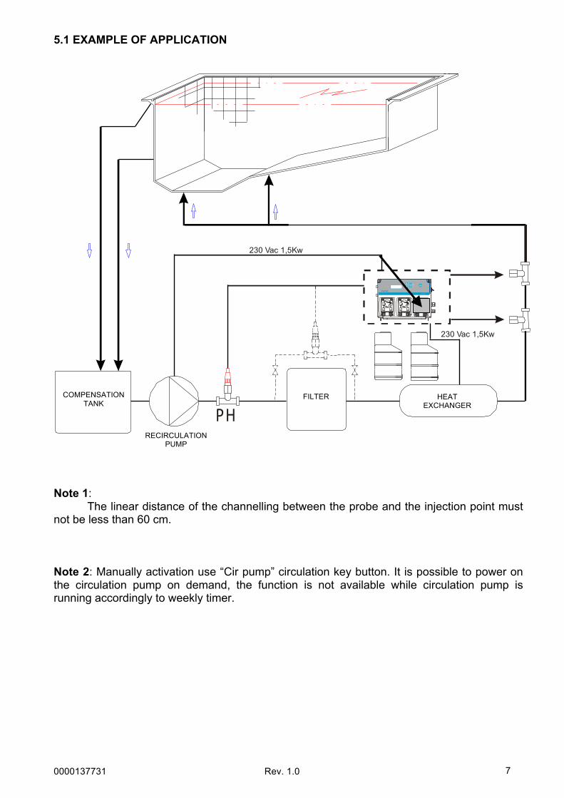
5.1 EXAMPLE OF APPLICATION
PH
230 Vac 1,5Kw
230 Vac 1,5Kw
Note 1: The linear distance of the channelling between the probe and the injection point must not be less than 60 cm. Note 2: Manually activation use “Cir pump” circulation key button. It is possible to power on the circulation pump on demand, the function is not available while circulation pump is running accordingly to weekly timer.
pH & ClDOSD O S
COMPENSATION TANK
RECIRCULATION PUMP
FILTER HEAT EXCHANGER
0000137731 Rev. 1.0
8
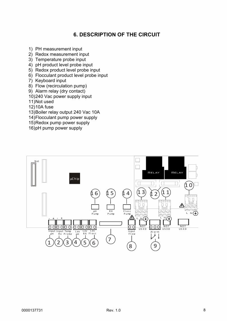
6. DESCRIPTION OF THE CIRCUIT
1) PH measurement input 2) Redox measurement input 3) Temperature probe input 4) pH product level probe input 5) Redox product level probe input 6) Flocculant product level probe input 7) Keyboard input 8) Flow (recirculation pump) 9) Alarm relay (dry contact) 10) 240 Vac power supply input 11) Not used 12) 10A fuse 13) Boiler relay output 240 Vac 10A 14) Flocculant pump power supply 15) Redox pump power supply 16) pH pump power supply
Al ar mInputF l ow
L evF l o c c
Net
µC h ip
R el ay R el ay R el ay
1 2 78
1 3
9
1 11 0
1 5 1 4
L evR X
L evpH
TempP r obe
InputR x
InputpH
3 4 5 6
pH
P ump
1 6
F l oc cP ump
R X
P ump
-‐ + -‐ +
1 2
NOT US E D
NOT US E D
NOT US E D

0000137731 Rev. 1.0
9
DISPLAY MODES WITH THE SYSTEM IN STAND-BY Press the Down and SET keys simultaneously to change the display mode. The two display modes are illustrated and described below:
*If AdvancedàFlow= On and the recirculation pump stops during Flocculant dosing, thereby blocking the dosing of the system, once the pump is reactivated the Flocculant will restart the calculated dose in cc from the beginning. N.B. The recirculation pump can be connected to the system. This function can be used when the system does not control the pump through a relay, but the signal comes from an autonomous pump.
N.B. If an alarm should occur, the system will automatically switch to Stand-by display mode 1, thereby displaying the alarm typology.
Stand-by Display Mode 1 Functionality
Alr 760mV 8.3pH
Alr 1200cc 760mV 8.3pH
Alr FLOC 37m 760mV 8.3pH
The display is divided into 4 parts: • When active, the alarm is shown on the
upper left. • Three elements are displayed on the
upper right: o The 1st is the display mode with
the system in stand-by. o The 2nd displays the countdown
of the amount being dosed by the pump in cc.
o The 3rd, with the message FLOC, is the expected time until the next dose.
• The value detected by the Rx probe is displayed on the lower left.
• The value detected by the pH probe is displayed on the lower right.
Stand-by Display Mode 2 Functionality
Ta 25°C Sp=27°C Wed 11:35
Ta 25°C Sp=27°C P01 11:30->12:30
The display is divided into 4 parts (Fig.1): • The temperature value detected by the
probe is displayed on the upper left. • The SetPoint of the boiler is displayed on
the upper right. When the relay is active, the value is flashing.
• The day of the week is displayed on the lower left.
• The clock is displayed on the lower right. When a program for the recirculation pump is activated, the program number, with the start and stop times flashing, is displayed on the bottom line. (fig. 2)
1
2
3
A = Up Key B = CAL/Enter Key C = SET/Esc Key D = Down Key E = Display F = Circulation Pump
2
1
pH & ClDOSD O SC
E A B F
D

0000137731 Rev. 1.0
10
7. CALIBRATION MENU 7.1 Calibration Before continuing, calibration must be enabled. Select AdvancedàCal from the menu. The display will show:
Exit the menu and return to the system’s normal status.
7.1.1 pH probe calibration (Easy)
Collect some water
Remove the probe from the probe holder
Wash the probe
Place the probe in the 7 pH buffer
solution
Press the Cal button for 3 seconds and use the same button to confirm
the pH Measurement
Calibration pH Measurement
Press Cal to start the calibration with
a pH 7 buffer solution
Press CAL B.Solut. 7pH
The calibration has a duration of 1 minute
Wait 59s B.Solut. 7pH
Probe quality
Quality B.Solut. 7pH
H O22
9 Wash the probe
1 0 Put the probe back in the probe holder and press Cal to end the procedure
Calibration Menu Display Settings
Advanced Cal Off
Press ENTER to access the menu.
Advanced Cal Full
Press Enter and use the + and - keys to modify the calibration settings:
• Full: The system calibrates the reading of the pH probe’s value based on 2 reference values (7 and 4 pH). This calibration mode allows the system to read the values with greater precision.
• Easy: The system calibrates the reading of the pH probe’s value based on one reference value (7 pH).
• Off: Calibration is disabled.

0000137731 Rev. 1.0
11
7.1.1 pH probe calibration (Full)
Collect some water
Remove the probe from the probe
holder
Wash the probe
Place the probe in the 7 pH buffer
solution
Press the Cal button for 3 seconds and use the same button to confirm
the pH Measurement
Calibration pH Measurement
Press Cal to start the calibration with a
pH 7 buffer solution
Press CAL B.Solut. 7pH
The calibration has a duration of 1
minute
Wait 59s B.Solut. 7pH
Probe quality
Quality B.Solut. 7pH
H O22
9 Wash the probe
4 pH3
10 Place the probe in the 4 pH buffer
solution
Press Cal to start the calibration with a pH 4 buffer solution
Press CAL B.Solut. 4pH
The calibration has a duration of 1
minute
Wait 59s B.Solut. 4pH
Probe quality
Quality B.Solut. 4pH
H O22
14 Wash the probe
1 5 Put the probe back in the probe holder
and press Cal to end the procedure

0000137731 Rev. 1.0
12
7.1.1 Redox probe calibration In order to perform this calibration, Redox measurement must be enabled
Collect some water
Remove the probe from the probe holder
Wash the probe
Place the probe in the 465 mV buffer
solution
Press the Cal button for 3 seconds and use the same button to confirm the Rx
Measurement
Calibration Rx Measurement
Press Cal to start the calibration
with a 465 mV buffer solution
Press CAL B.Solut. 465 mV
The calibration has a duration of 1
minute
Wait 59s B.Solut. 465 mV
Probe quality
Quality B.Solut. 465 mV
H O22
9 Wash the probe
1 0 Put the probe back in the probe holder and press Cal to end the procedure
7.1.4 Temperature calibration This function is only present if a temperature probe is connected. This operation allows the probe to provide an even more precise reading wherever necessary.
1 Use a portable instrument or a
simple thermometer to measure the temperature of the water
Press the Cal button for 3 seconds
and use the same button to confirm the Temperature
Temperature Calibration
Use the Up and Down buttons to insert the detected temperature value and press the CAL button to confirm.
Press CAL T= 25

0000137731 Rev. 1.0
13
8. PROGRAMMING Press the Cal and Set buttons simultaneously for at least 3 seconds to access the programming menu. After releasing the buttons, the display will show:
To prime the pH pump, press the UP button for at least 3 seconds and release it to complete the operation. Follow the same procedure using the DOWN button to prime the Rx pump and using the UP and DOWN buttons simultaneously to prime the Flocculant pump.
Menu pH Measurement
Press Enter to access the submenus: • Setpoint • Dose type • OFA time • Alr Band • Type
pH Measurement Setpoint 7.4 pH
Press Enter and use the + and - keys to modify the Set Point value (0-14 pH)
pH Measurement Dose Type Acid
Press Enter and use the + and - keys to modify the Set Point typology:
• Acid • Alkaline
pH Measurement OFA Time Off
Press Enter and use the + and - keys to set the OFA time to OFF or to a value between 1 and 240 min. (See section 9.5)
pH Measurement Alr Band 3.0pH
Press Enter and use the + and - keys to set the band alarm to a value between 1 and 3 pH.
pH Measurement Type PROP
Press Enter and use the + and - keys to modify the dose type:
• PROP (See Section 9.2) • ON/OFF (See Section 9.4) • OFF (Dose disabled)
Display Language Settings
Menu Language EN
Press Enter and use the + and - keys to change the selected language: FR, EN, IT, ES, DE
pH Measurement Display Settings
0000137731 Rev. 1.0
14
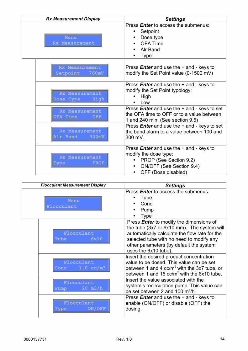
Menu Rx Measurement
Press Enter to access the submenus: • Setpoint • Dose type • OFA Time • Alr Band • Type
Rx Measurement Setpoint 760mV
Press Enter and use the + and - keys to modify the Set Point value (0-1500 mV)
Rx Measurement Dose Type High
Press Enter and use the + and - keys to modify the Set Point typology:
• High • Low
Rx Measurement OFA Time Off
Press Enter and use the + and - keys to set the OFA time to OFF or to a value between 1 and 240 min. (See section 9.5)
Rx Measurement Alr Band 300mV
Press Enter and use the + and - keys to set the band alarm to a value between 100 and 300 mV.
Rx Measurement Type PROP
Press Enter and use the + and - keys to modify the dose type:
• PROP (See Section 9.2) • ON/OFF (See Section 9.4) • OFF (Dose disabled)
Rx Measurement Display Settings
Flocculant Measurement Display Settings
Menu Flocculant
Press Enter to access the submenus: • Tube • Conc • Pump • Type
Flocculant Tube 6x10
Press Enter to modify the dimensions of the tube (3x7 or 6x10 mm). The system will automatically calculate the flow rate for the selected tube with no need to modify any other parameters (by default the system uses the 6x10 tube).
Flocculant Conc 1.0 cc/m3
Insert the desired product concentration value to be dosed. This value can be set between 1 and 4 cc/m3 with the 3x7 tube, or between 1 and 15 cc/m3 with the 6x10 tube.
Flocculant Pump 20 m3/h
Insert the value associated with the system’s recirculation pump. This value can be set between 2 and 100 m³/h.
Flocculant Type ON/OFF
Press Enter and use the + and - keys to enable (ON/OFF) or disable (OFF) the dosing.

0000137731 Rev. 1.0
15
Menu Boiler
Press Enter to access the submenus: • Setpoint • Type • OFA Time
Boiler Setpoint 25°C
Press Enter and use the + and – keys to modify the Set Point value (15-60 °C), or rather the value at which the relay opens or closes based on the Dose Type settings.
Boiler Type High
Press Enter and use the + and - keys to modify the Set Point typology:
• High: the relay is active until the Set Point temperature is reached. The activation is present for temperatures higher than the Set Point value.
• Low: the relay is active until the Set Point temperature is reached. The activation is present for temperatures lower than the Set Point value.
Boiler OFA Time Off
Press Enter and use the + and - keys to set the OFA time to OFF or to a value between 1 and 240 min. This is the time for which the relay will be disabled if the temperature detected by the probe does not reach the Set Point value.
* if the temperature probe is not present, the display will show an Error message upon accessing the menu. This menu item is only enabled if a temperature probe is connected.
Boiler Display Settings
0000137731 Rev. 1.0
16
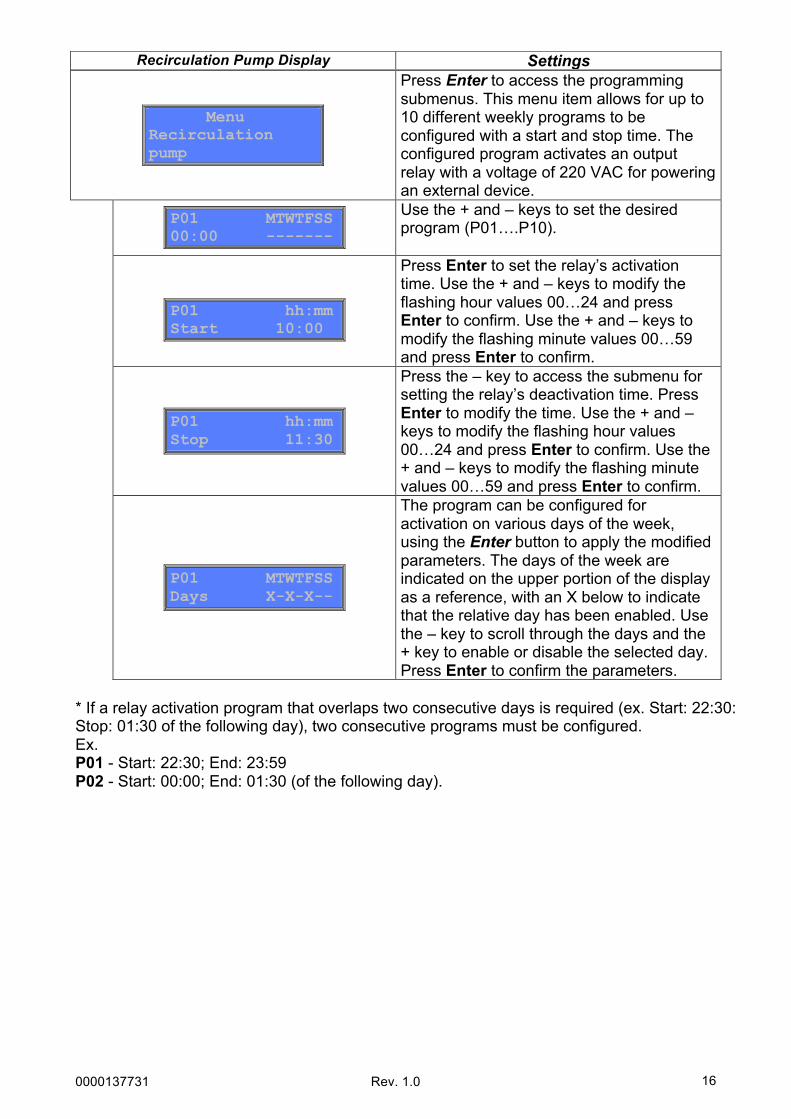
Menu Recirculation pump
Press Enter to access the programming submenus. This menu item allows for up to 10 different weekly programs to be configured with a start and stop time. The configured program activates an output relay with a voltage of 220 VAC for powering an external device.
P01 MTWTFSS 00:00 -------
Use the + and – keys to set the desired program (P01….P10).
P01 hh:mm Start 10:00
Press Enter to set the relay’s activation time. Use the + and – keys to modify the flashing hour values 00…24 and press Enter to confirm. Use the + and – keys to modify the flashing minute values 00…59 and press Enter to confirm.
P01 hh:mm Stop 11:30
Press the – key to access the submenu for setting the relay’s deactivation time. Press Enter to modify the time. Use the + and – keys to modify the flashing hour values 00…24 and press Enter to confirm. Use the + and – keys to modify the flashing minute values 00…59 and press Enter to confirm.
P01 MTWTFSS Days X-X-X--
The program can be configured for activation on various days of the week, using the Enter button to apply the modified parameters. The days of the week are indicated on the upper portion of the display as a reference, with an X below to indicate that the relative day has been enabled. Use the – key to scroll through the days and the + key to enable or disable the selected day. Press Enter to confirm the parameters.
* If a relay activation program that overlaps two consecutive days is required (ex. Start: 22:30: Stop: 01:30 of the following day), two consecutive programs must be configured. Ex. P01 - Start: 22:30; End: 23:59 P02 - Start: 00:00; End: 01:30 (of the following day).
Recirculation Pump Display Settings

0000137731 Rev. 1.0
17
Advanced Display Settings
Menu Advanced
Press Enter to access the submenus: • Temp. • Flow • Cal • Date-Time • Password • Total reset • Enable boiler • Enable r. pump
Advanced Temp. 25°C
Press Enter and use the + and - keys to set the compensation temperature to a value from 1 to 100 °C. If a temperature probe is connected, this menu item will not be displayed and the system will automatically compensate based on the value detected by the probe.
Advanced Flow On
Press Enter and use the + and - keys to set the flow to OFF or ON. This menu item enables or disables the Flow input. (See Section 10.0).
Advanced Cal Full
Press Enter and use the + and - keys to modify the calibration settings:
• Full: The system calibrates the reading of the pH probe’s value based on 2 reference values (7 and 4 pH). This calibration mode allows the system to read the values with greater precision.
• Easy: The system calibrates the reading of the pH probe’s value based on 1 reference value (7 pH).
• Off: Calibration is disabled.
Date-Time Fri 11:36
Press Enter to set the time and the day of the week. The reference value will flash. Use the + and - keys to make any desired changes and press Enter to confirm.
Advanced Password ****
Press Enter to set the security password for accessing and modifying the system’s parameters. Use the + key to modify the selected value, the – key to move on to the next character and the Enter key to confirm.
Advanced Total reset
Press Enter to reset the system’s settings. Press Enter again to confirm the reset operation (the system’s default parameters will be loaded).
Enable boiler Yes
Press Enter and use the + and - keys to enable (Yes) or disable (No) the boiler relay’s output.
Enable Recirc. Yes
Press Enter and use the + and - keys to enable (Yes) or disable (No) the recirculation pump relay’s output.

0000137731 Rev. 1.0
18
Press Esc to exit the various menus and Enter to confirm the settings.
HOTKEYS With the system in stand-by, press the SET button for at least 3 seconds to access a quick setup menu:
Display Settings
Menu Save YES
Use the + and – keys to select YES or NO, indicating whether or not to save the settings. Press Enter to confirm the operation.
Set Display Functionality
pH= 7.2 Rx= 760 Floc= 1.0cc/m3
The pH value flashes. Use the + and – keys to make any desired modifications and press Enter to continue and move on to the Rx or Flocculant value. Continue using the same procedure, pressing Enter to confirm and exit.

0000137731 Rev. 1.0
19
9. DOSING METHOD
The control of the pumps in the pH and Redox scale takes place by means of a PWM function. The proportional band is fixed on the values: pH = 0.8 and Redox = 120 mV 9.1 pH/Redox Proportional Dosing The instrument allows for the chemical measurement to be modified and monitored automatically through the pH Set Point, adjusting the dose through the pH/Redox motor commanded in Proportional Time mode. The dosage indicated below can be obtained by setting the following parameters:
Ø pH Set point = 7.20 pH Ø Dose type = Alkaline Ø Proportional Band = 0.80 pH
Set Point pH
Prop. Band
Motore pH
pH Motor
pH Set Point

0000137731 Rev. 1.0
20
9.2 pH/Redox ON/OFF Dosing The instrument allows for the chemical measurement to be modified and monitored automatically through the pH Set Point, adjusting the dose through the pH motor commanded in ON/OFF mode. The dosage indicated below can be obtained by setting the following parameters:
Ø pH Set point = 7.20 pH Ø Dose type = Alkaline
Set Point pH
Motore pH
9.3 pH/Redox Set Point Alarm By configuring the Band alarm, a working window is created. If the configured limits are exceeded, the alarm relay closes and remains closed until the measurement is restored or until the enter key is pressed to deactivate the alarm. By configuring the OFA (Over Feed Alarm) time, the dose of the pH/Redox Set Point is monitored over time, divided into two alarms:
Ø At 70% of the set time the first alarm is shown on the display and the alarm relay closes.
Ø At 100% of the set time the second alarm is shown on the display, the alarm relay closes and the pH/Redox motor shuts down.
Press Enter to cancel the alarm and initiate the OFA time.
Motore pH
Set Point pH
ALR Relè
ALR Band
ALR Band
ALR Relay
pH Motor
pH Set Point
pH Motor
pH Set Point

0000137731 Rev. 1.0
21
10. ACTIVATIONS Flow function
By means of the recirculation pump. High voltage 100 – 240 Vac input, the dosing system is on. High voltage input is off (the recirculation pump is off), the dosing system displays FLOW flashing.
11. ALARMS
Lev pH= pH product level probe alarm. Lev Rx= Rx product level probe alarm. Lev Flocc= Flocculant product level probe alarm. OFA pH/Rx= Set Point not reached with the OFA time set* Band pH/RX= this alarm message is displayed when the detected value is outside of the SetPoint by +/- the set band value.
*At 70% of the set time the system displays the alarm and activates the alarm relay, at 100% it shuts down the motor. The alarm can be reset by pressing the Enter key. Pressing the Enter key with the alarm active deactivates the alarm relay, leaving only the alarm message on the display.
12. DEFAULT CONTROL PARAMETERS
To reset the default parameters and values, do the following:
• Disconnect the device • Hold down the + and – keys simultaneously and connect the device • Confirm the selection to restore the default parameters
Default parameters:
• Configuration = pH/Rx/Flocc • Language = UK (English) • pH Set Point = 7.4 pH; Acid; Off; 3pH PROP • Rx Set Point = 750mV; Low; OFF; Alr Band 300mV; PROP • Flocculant = 6x10; 1.0cc/ m3; 20 m3/h • Temperature = 25°C • Calibration = FULL • Flow Input = OFF • Password = Disabled • Boiler enabled = YES • Recirculation pump enabled = YES

0000137731 Rev. 1.0
22
13. LIST OF POSSIBLE ANOMALIES AND RELATIVE SOLUTIONS
ANOMALY CAUSE SOLUTION The instrument always indicates a pH value of 7.00
Cable and/or connector problem.
1) check for any short circuits on the electrode ↔ instrument connection cable (between the central core of the cable and the external shielding). 2) Make sure there are no traces of humidity and/or condensation on the probe’s connector or the device. 3) Make sure that the 100Ω resistance is present between terminals 11 and 12.
The instrument always indicates a high or constantly unstable value
Electrode connection cable damaged. Check the cable.
Air bubble in the membrane of the electrode.
Place the electrode in a vertical position and shake it gently until the air bubble rises. N.B.: The electrode must be in a vertical position or at a maximum angle of 45°.
Electrode consumed. Replace the electrode. Connection cable too long or too close to an electrical cable: disturbances.
Reduce the distance between the device and the probe.
Impossible to calibrate the value of pH 7 Error shown on the display pH probe calibration quality < 20%
Inadequate buffer solution.
Make sure that the solution being utilised has a pH value of 7. Check the pH of the buffer solution with an electronic pH meter.
Use a new pH 7 buffer solution and repeat the calibration.
Problem on the porous material of the probe, dirt residues.
Make sure that the porous material of the probe is in good condition; wash the electrode with a diluted acid-based solution and dry it with a soft cloth.
Electrode consumed. Replace the electrode. Impossible to calibrate the value of pH 4 Error shown on the display pH probe calibration quality < 20%
Inadequate buffer solution.
Make sure that the solution being utilised has a pH value of 4. Check the pH of the buffer solution with an electronic pH meter.
Use a new pH 4 buffer solution and repeat the calibration.
Problem in the bulb of the electrode.
Make sure that the bulb of the electrode is not damaged. Make sure that it has not dried outside of the water. As a last resort, clean the electrode and leave it immersed in the water for a few hours.
Electrode consumed. Replace the electrode. Slow electrode response
Electrode electro-statically charged.
During the calibration phase, the electrode MUST NOT be dried with a cloth or paper towel; let it drip dry.
0000137731 Rev. 1.0
23
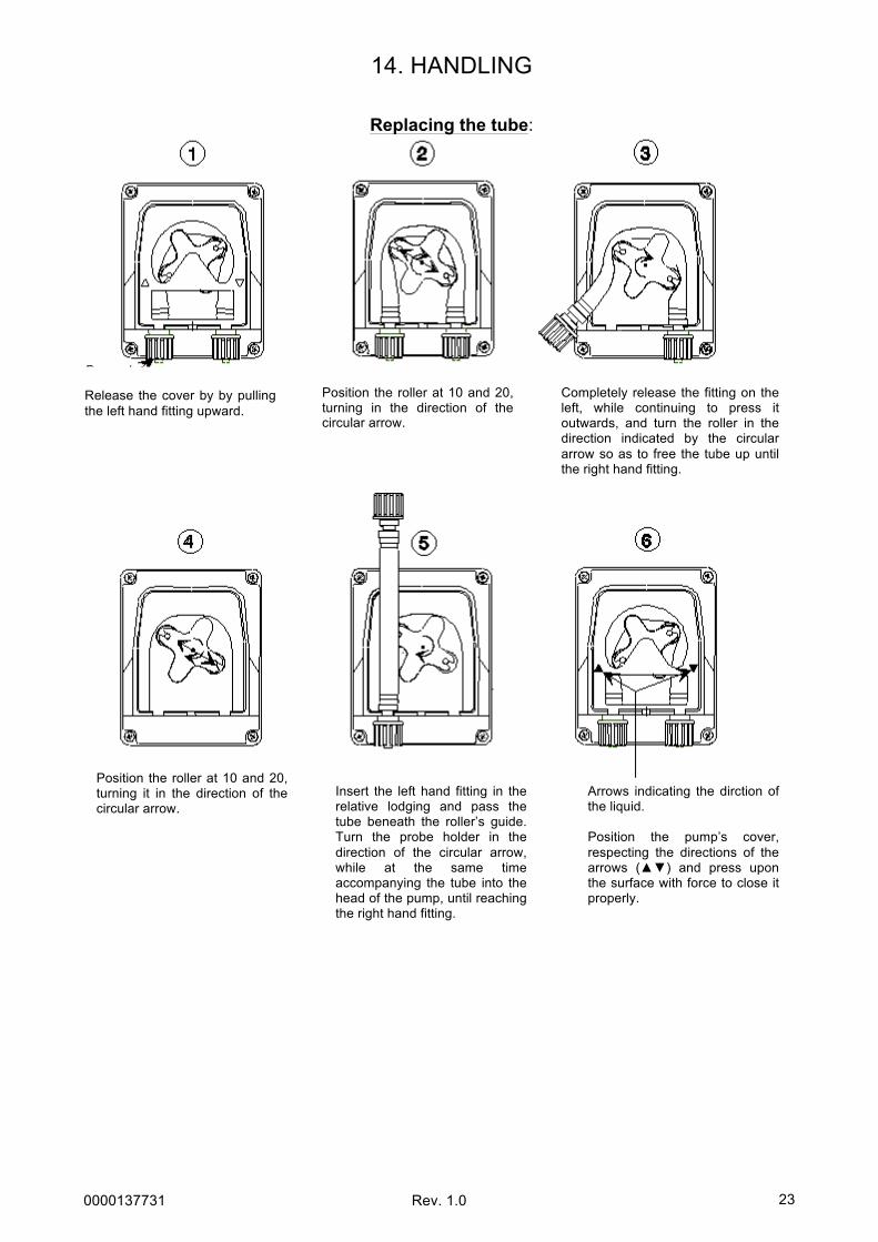
14. HANDLING
Replacing the tube:
Release the cover by by pulling the left hand fitting upward.
Position the roller at 10 and 20, turning in the direction of the circular arrow.
Completely release the fitting on the left, while continuing to press it outwards, and turn the roller in the direction indicated by the circular arrow so as to free the tube up until the right hand fitting.
Position the roller at 10 and 20, turning it in the direction of the circular arrow.
Insert the left hand fitting in the relative lodging and pass the tube beneath the roller’s guide. Turn the probe holder in the direction of the circular arrow, while at the same time accompanying the tube into the head of the pump, until reaching the right hand fitting.
Arrows indicating the dirction of the liquid. Position the pump’s cover, respecting the directions of the arrows (▲▼) and press upon the surface with force to close it properly.

0000137731 Rev. 1.0
24
15. STORING THE PUMP AFTER USE
Before storing the regulation device, it is recommended to rinse the tube by pumping clean water. Next, position the probe holder at 7 and 05, turning it in the direction indicated by the circular arrow. These two precautions will facilitate the device’s subsequent reactivation.

0000137731 Rev. 1.0
25
WARNINGS
PRODUCTS TO BE UTILIZED: • Reducing the pH value: sulphuric acid based product, easily available on the market.
• Increasing the pH value: alkaline acid based product
PRODUCTS NOT RECOMMENDED • Do not use hydrochloric acid.
For all other products, please consult the installer.
WARNINGS REGARDING THE PROBE • Handle the probe with CAUTION. • DO NOT INSERT AN EXCESSIVE AMOUNT of chemical product upstream from the
probe. • Storing the probe: Extract the pH probe from the relative probe holder. Store it in its
original container filled with tap water. If necessary, close the probe holder with a cap the size of a 5 cent Euro coin.
As the pH electrode is made up of glass elements, it must be handled with care. All of our electrodes are tested extensively during production before being packaged. Electrode repairs under warranty are not foreseen unless they should fail to function upon their first activation. Packaging is excluded. In this case, in order for the probe to be accepted for review, it absolutely must be received in its original packaging, along with its relative bottle filled with water.
BEWARE OF THE FUMES
SERBATOIOTANKRESERVOIRTANK
2 mtpH & ClDOSD O S