![MELSEC iQ-F FX5U User's Manual (Hardware)...This manual classifies the safety precautions into two categories: [ WARNING] and [ CAUTION]. Depending on the circumstances, procedures](https://static.fdocuments.us/doc/165x107/5e72abeddb688d6156521158/melsec-iq-f-fx5u-users-manual-hardware-this-manual-classifies-the-safety.jpg)
00 CV 3P329626-1 - daikinac.com · English 1 Safety Precautions • Read these Safety Precautions...
18
INSTALLATION MANUAL BP (Branch Provider) Unit Models BPMKS048A2U BPMKS049A3U English Français Español Installation manual BP (Branch Provider) Unit Manuel d’installation Unité BP (Fournisseur de branchement) Manual de instalación Unidad BP (Proveedor de ramificaciones)
-
Upload
truongkhanh -
Category
Documents
-
view
217 -
download
0
Transcript of 00 CV 3P329626-1 - daikinac.com · English 1 Safety Precautions • Read these Safety Precautions...
INSTALLATION MANUALBP (Branch Provider) Unit
Models BPMKS048A2UBPMKS049A3U
English
Français
Español
Installation manualBP (Branch Provider) Unit
Manuel d’installationUnité BP (Fournisseur de branchement)
Manual de instalaciónUnidad BP (Proveedor de ramificaciones)
00_CV_3P329626-1.fm Page 1 Thursday, November 8, 2012 11:52 AM
English 1
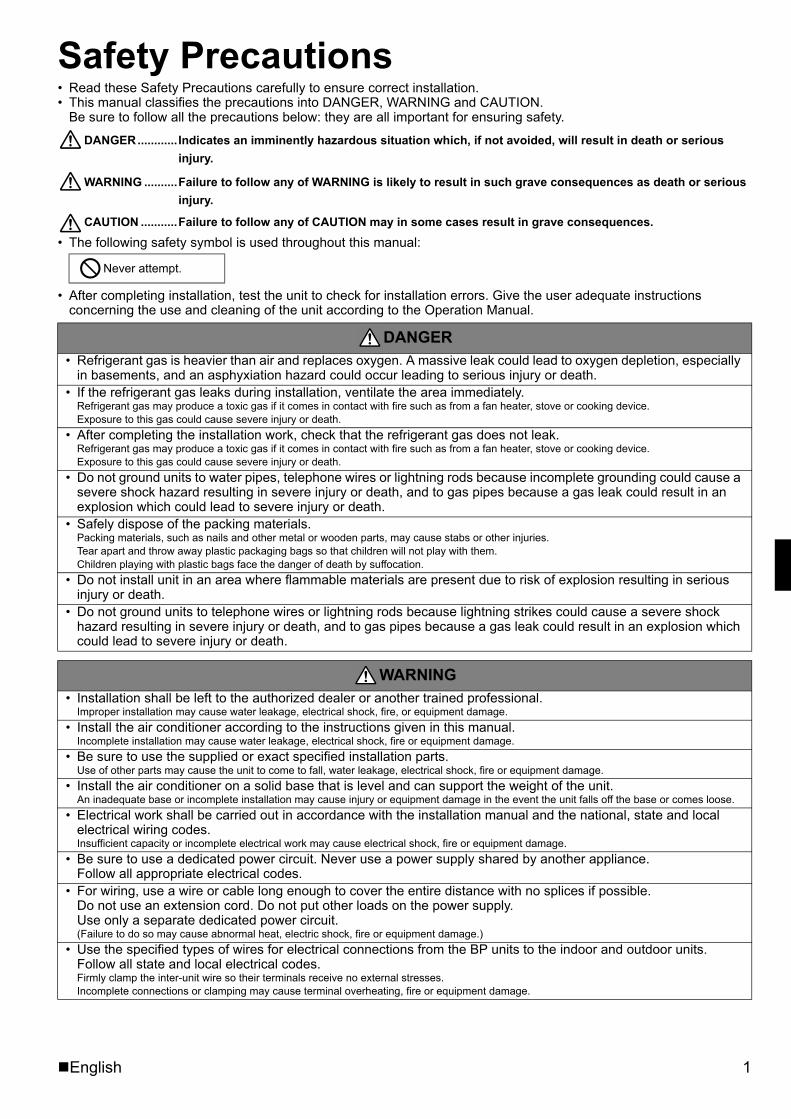
Safety Precautions• Read these Safety Precautions carefully to ensure correct installation.• This manual classifies the precautions into DANGER, WARNING and CAUTION.
Be sure to follow all the precautions below: they are all important for ensuring safety.
DANGER............ Indicates an imminently hazardous situation which, if not avoided, will result in death or serious injury.
WARNING ..........Failure to follow any of WARNING is likely to result in such grave consequences as death or serious injury.
CAUTION ...........Failure to follow any of CAUTION may in some cases result in grave consequences.• The following safety symbol is used throughout this manual:
• After completing installation, test the unit to check for installation errors. Give the user adequate instructions concerning the use and cleaning of the unit according to the Operation Manual.
Never attempt.
DANGER• Refrigerant gas is heavier than air and replaces oxygen. A massive leak could lead to oxygen depletion, especially
in basements, and an asphyxiation hazard could occur leading to serious injury or death.• If the refrigerant gas leaks during installation, ventilate the area immediately.
Refrigerant gas may produce a toxic gas if it comes in contact with fire such as from a fan heater, stove or cooking device. Exposure to this gas could cause severe injury or death.
• After completing the installation work, check that the refrigerant gas does not leak. Refrigerant gas may produce a toxic gas if it comes in contact with fire such as from a fan heater, stove or cooking device. Exposure to this gas could cause severe injury or death.
• Do not ground units to water pipes, telephone wires or lightning rods because incomplete grounding could cause a severe shock hazard resulting in severe injury or death, and to gas pipes because a gas leak could result in an explosion which could lead to severe injury or death.
• Safely dispose of the packing materials.Packing materials, such as nails and other metal or wooden parts, may cause stabs or other injuries. Tear apart and throw away plastic packaging bags so that children will not play with them. Children playing with plastic bags face the danger of death by suffocation.
• Do not install unit in an area where flammable materials are present due to risk of explosion resulting in serious injury or death.
• Do not ground units to telephone wires or lightning rods because lightning strikes could cause a severe shock hazard resulting in severe injury or death, and to gas pipes because a gas leak could result in an explosion which could lead to severe injury or death.
WARNING• Installation shall be left to the authorized dealer or another trained professional.
Improper installation may cause water leakage, electrical shock, fire, or equipment damage.• Install the air conditioner according to the instructions given in this manual.
Incomplete installation may cause water leakage, electrical shock, fire or equipment damage.• Be sure to use the supplied or exact specified installation parts.
Use of other parts may cause the unit to come to fall, water leakage, electrical shock, fire or equipment damage.• Install the air conditioner on a solid base that is level and can support the weight of the unit.
An inadequate base or incomplete installation may cause injury or equipment damage in the event the unit falls off the base or comes loose.• Electrical work shall be carried out in accordance with the installation manual and the national, state and local
electrical wiring codes.Insufficient capacity or incomplete electrical work may cause electrical shock, fire or equipment damage.
• Be sure to use a dedicated power circuit. Never use a power supply shared by another appliance. Follow all appropriate electrical codes.
• For wiring, use a wire or cable long enough to cover the entire distance with no splices if possible. Do not use an extension cord. Do not put other loads on the power supply. Use only a separate dedicated power circuit.(Failure to do so may cause abnormal heat, electric shock, fire or equipment damage.)
• Use the specified types of wires for electrical connections from the BP units to the indoor and outdoor units. Follow all state and local electrical codes. Firmly clamp the inter-unit wire so their terminals receive no external stresses. Incomplete connections or clamping may cause terminal overheating, fire or equipment damage.
01_EN_3P329626-1.fm Page 1 Friday, November 9, 2012 11:10 AM
2 English
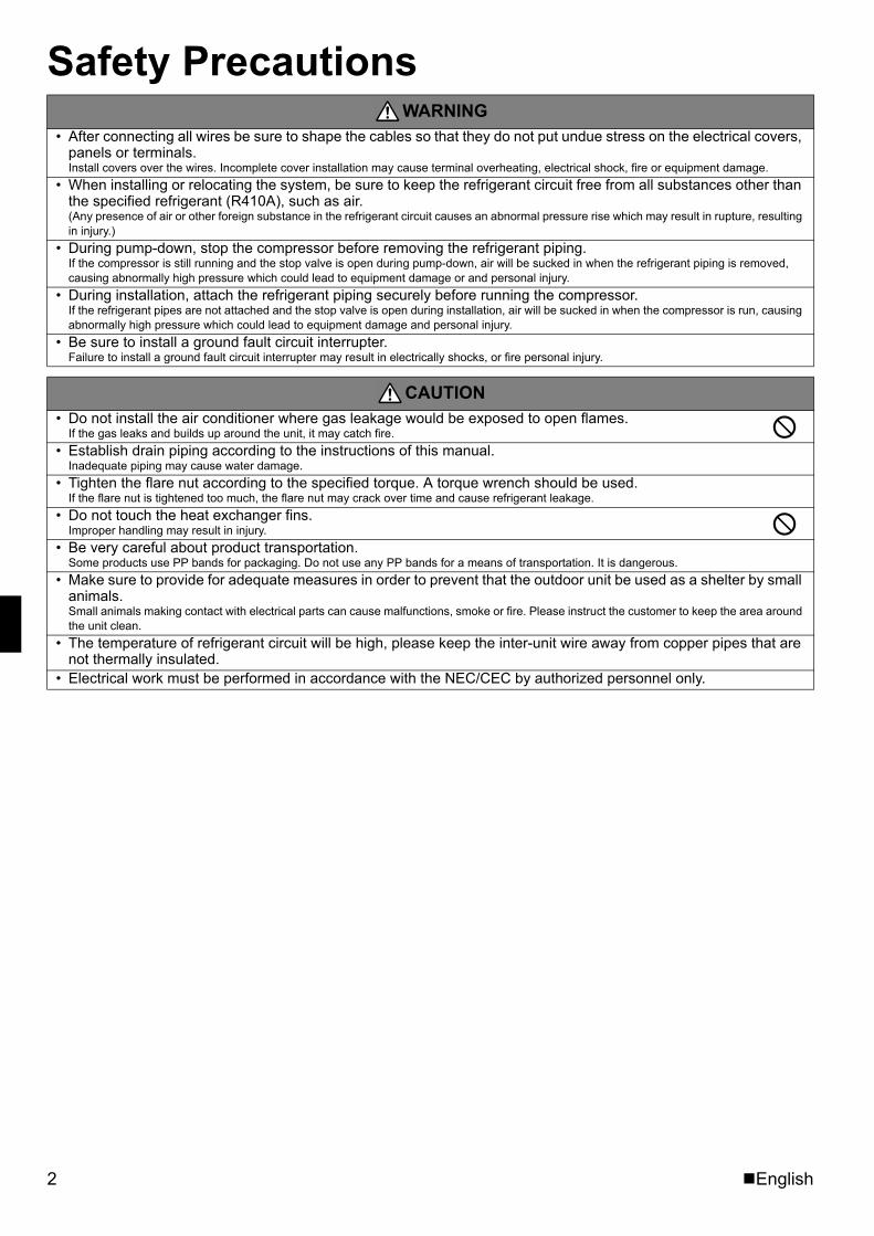
Safety PrecautionsWARNING
• After connecting all wires be sure to shape the cables so that they do not put undue stress on the electrical covers, panels or terminals.Install covers over the wires. Incomplete cover installation may cause terminal overheating, electrical shock, fire or equipment damage.
• When installing or relocating the system, be sure to keep the refrigerant circuit free from all substances other than the specified refrigerant (R410A), such as air.(Any presence of air or other foreign substance in the refrigerant circuit causes an abnormal pressure rise which may result in rupture, resulting in injury.)
• During pump-down, stop the compressor before removing the refrigerant piping.If the compressor is still running and the stop valve is open during pump-down, air will be sucked in when the refrigerant piping is removed, causing abnormally high pressure which could lead to equipment damage or and personal injury.
• During installation, attach the refrigerant piping securely before running the compressor.If the refrigerant pipes are not attached and the stop valve is open during installation, air will be sucked in when the compressor is run, causing abnormally high pressure which could lead to equipment damage and personal injury.
• Be sure to install a ground fault circuit interrupter.Failure to install a ground fault circuit interrupter may result in electrically shocks, or fire personal injury.
CAUTION• Do not install the air conditioner where gas leakage would be exposed to open flames.
If the gas leaks and builds up around the unit, it may catch fire.• Establish drain piping according to the instructions of this manual.
Inadequate piping may cause water damage. • Tighten the flare nut according to the specified torque. A torque wrench should be used.
If the flare nut is tightened too much, the flare nut may crack over time and cause refrigerant leakage.• Do not touch the heat exchanger fins.
Improper handling may result in injury.• Be very careful about product transportation.
Some products use PP bands for packaging. Do not use any PP bands for a means of transportation. It is dangerous.• Make sure to provide for adequate measures in order to prevent that the outdoor unit be used as a shelter by small
animals.Small animals making contact with electrical parts can cause malfunctions, smoke or fire. Please instruct the customer to keep the area around the unit clean.
• The temperature of refrigerant circuit will be high, please keep the inter-unit wire away from copper pipes that are not thermally insulated.
• Electrical work must be performed in accordance with the NEC/CEC by authorized personnel only.
01_EN_3P329626-1.fm Page 2 Friday, November 9, 2012 11:10 AM
English 3
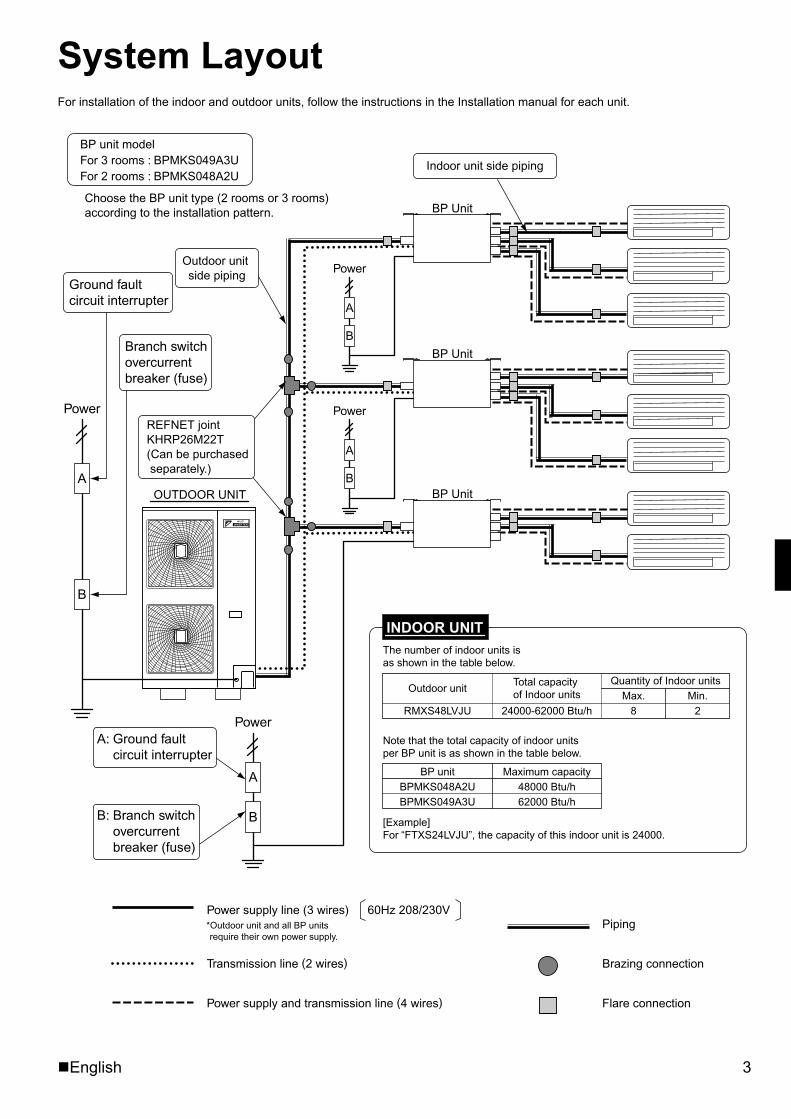
System LayoutFor installation of the indoor and outdoor units, follow the instructions in the Installation manual for each unit.
B
A
Power
B
A
Power
B
A
Power
B
A
Power
BP Unit
BP Unit
BP Unit
Flare connection
OUTDOOR UNIT
REFNET jointKHRP26M22T(Can be purchased separately.)
A: Ground fault circuit interrupter
B: Branch switch overcurrent breaker (fuse)
Ground fault circuit interrupter
Branch switch overcurrent breaker (fuse)
Power supply line (3 wires) 60Hz 208/230V
Transmission line (2 wires)
Power supply and transmission line (4 wires)
Piping
Brazing connection
Indoor unit side piping
Outdoor unit side piping
*Outdoor unit and all BP units require their own power supply.
BP unit modelFor 3 rooms : BPMKS049A3UFor 2 rooms : BPMKS048A2U
Choose the BP unit type (2 rooms or 3 rooms) according to the installation pattern.
BP unit Maximum capacityBPMKS048A2U 48000 Btu/hBPMKS049A3U 62000 Btu/h
The number of indoor units is as shown in the table below.
Note that the total capacity of indoor units per BP unit is as shown in the table below.
[Example]For “FTXS24LVJU”, the capacity of this indoor unit is 24000.
INDOOR UNIT
Outdoor unitTotal capacity of Indoor units
Quantity of Indoor unitsMin.
RMXS48LVJU 24000-62000 Btu/h 2Max.
8
01_EN_3P329626-1.fm Page 3 Friday, November 9, 2012 11:10 AM
4 English
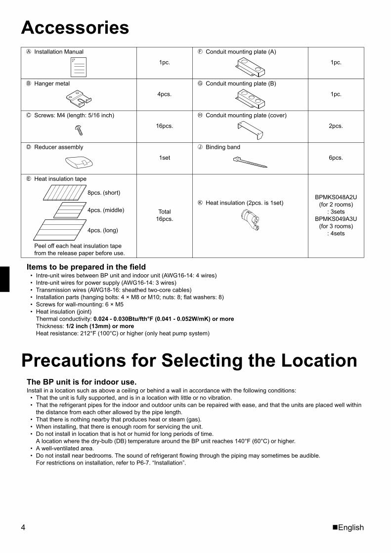
Accessories
Items to be prepared in the field• Intre-unit wires between BP unit and indoor unit (AWG16-14: 4 wires)• Intre-unit wires for power supply (AWG16-14: 3 wires)• Transmission wires (AWG18-16: sheathed two-core cables)• Installation parts (hanging bolts: 4 × M8 or M10; nuts: 8; flat washers: 8)• Screws for wall-mounting: 6 × M5• Heat insulation (joint)
Thermal conductivity: 0.024 - 0.030Btu/fth°F (0.041 - 0.052W/mK) or more Thickness: 1/2 inch (13mm) or more Heat resistance: 212°F (100°C) or higher (only heat pump system)
Precautions for Selecting the LocationThe BP unit is for indoor use.Install in a location such as above a ceiling or behind a wall in accordance with the following conditions:
• That the unit is fully supported, and is in a location with little or no vibration.• That the refrigerant pipes for the indoor and outdoor units can be repaired with ease, and that the units are placed well within
the distance from each other allowed by the pipe length.• That there is nothing nearby that produces heat or steam (gas).• When installing, that there is enough room for servicing the unit.• Do not install in location that is hot or humid for long periods of time.
A location where the dry-bulb (DB) temperature around the BP unit reaches 140°F (60°C) or higher.• A well-ventilated area.• Do not install near bedrooms. The sound of refrigerant flowing through the piping may sometimes be audible.
For restrictions on installation, refer to P6-7. “Installation”.
Installation Manual
1pc.
Conduit mounting plate (A)
1pc.
Hanger metal
4pcs.
Conduit mounting plate (B)
1pc.
Screws: M4 (length: 5/16 inch)
16pcs.
Conduit mounting plate (cover)
2pcs.
Reducer assembly
1set
Binding band
6pcs.
Heat insulation tape
Peel off each heat insulation tape from the release paper before use.
Total 16pcs.
Heat insulation (2pcs. is 1set) BPMKS048A2U
(for 2 rooms): 3sets
BPMKS049A3U(for 3 rooms)
: 4sets
A F
B G
C H
D J
E
8pcs. (short)
4pcs. (middle)
4pcs. (long)
K
01_EN_3P329626-1.fm Page 4 Friday, November 9, 2012 11:10 AM
English 5
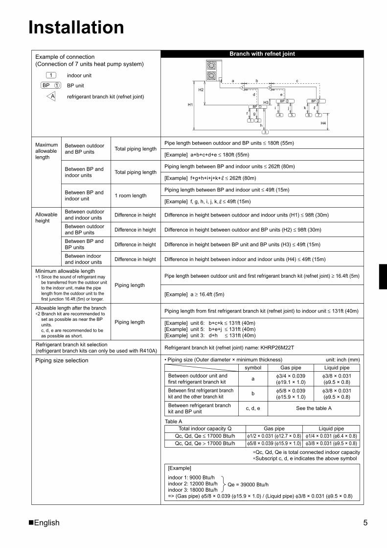
Installation
Piping length
Piping length
Pipe length between outdoor unit and first refrigerant branch kit (refnet joint) ≥ 16.4ft (5m)
[Example] a ≥ 16.4ft (5m)
[Example] unit 6: b+c+k ≤ 131ft (40m)[Example] unit 5: b+e+j ≤ 131ft (40m)[Example] unit 3: d+h ≤ 131ft (40m)
Piping length from first refrigerant branch kit (refnet joint) to indoor unit ≤ 131ft (40m)
Minimum allowable length∗1 Since the sound of refrigerant may
be transferred from the outdoor unit to the indoor unit, make the pipe length from the outdoor unit to the first junction 16.4ft (5m) or longer.
Allowable length after the branch∗2 Branch kit are recommended to
set as possible as near the BP units. c, d, e are recommended to be as possible as short.
Example of connection(Connection of 7 units heat pump system)
indoor unit
BP unit
refrigerant branch kit (refnet joint)
Branch with refnet joint
Pipe length between outdoor and BP units ≤ 180ft (55m)
[Example] a+b+c+d+e ≤ 180ft (55m)
Piping length between BP and indoor units ≤ 262ft (80m)
[Example] f+g+h+i+j+k+ ≤ 262ft (80m)
Piping length between BP and indoor unit ≤ 49ft (15m)
[Example] f, g, h, i, j, k, ≤ 49ft (15m)
Difference in height between outdoor and indoor units (H1) ≤ 98ft (30m)
Difference in height between outdoor and BP units (H2) ≤ 98ft (30m)
Difference in height between BP unit and BP units (H3) ≤ 49ft (15m)
Difference in height between indoor and indoor units (H4) ≤ 49ft (15m)
Refrigerant branch kit (refnet joint) name: KHRP26M22T
Maximum allowable length
Between indoor and indoor units
Between BP and BP units
Between outdoor and BP units
Between outdoor and indoor units
Between BP and indoor unit
Between BP and indoor units
Between outdoor and BP units
Difference in height
Difference in height
Difference in height
Difference in height
1 room length
Total piping length
Total piping length
Allowable height
Refrigerant branch kit selection (refrigerant branch kits can only be used with R410A)
Piping size selection
a
1 2
BP
BP
3
4 5 6
d
f g
h
i j k
e
b c
H1
H4
H2
H3
A
1
2 BP 3
B
7
1
A
BP 1
[Example]
indoor 1: 9000 Btu/hindoor 2: 12000 Btu/hindoor 3: 18000 Btu/h=> (Gas pipe) φ5/8 × 0.039 (φ15.9 × 1.0) / (Liquid pipe) φ3/8 × 0.031 (φ9.5 × 0.8)
Qe = 39000 Btu/h
• Piping size (Outer diameter × minimum thickness) unit: inch (mm)
Between refrigerant branch kit and BP unit
Between first refrigerant branch kit and the other branch kit
Between outdoor unit and first refrigerant branch kit
symbol
a
b
c, d, e
Gas pipe Liquid pipe
φ3/4 × 0.039(φ19.1 × 1.0)
φ5/8 × 0.039(φ15.9 × 1.0)
φ3/8 × 0.031(φ9.5 × 0.8)
φ3/8 × 0.031(φ9.5 × 0.8)
See the table A
Total indoor capacity QQc, Qd, Qe ≤ 17000 Btu/hQc, Qd, Qe > 17000 Btu/h
Gas pipe Liquid pipeφ1/2 × 0.031 (φ12.7 × 0.8)φ5/8 × 0.039 (φ15.9 × 1.0)
φ1/4 × 0.031 (φ6.4 × 0.8)φ3/8 × 0.031 (φ9.5 × 0.8)
Table A
∗Qc, Qd, Qe is total connected indoor capacity∗Subscript c, d, e indicates the above symbol
01_EN_3P329626-1.fm Page 5 Friday, November 9, 2012 11:10 AM
6 English
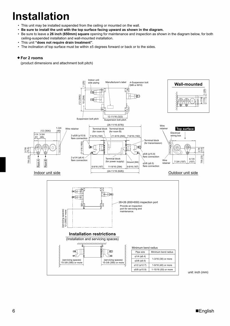
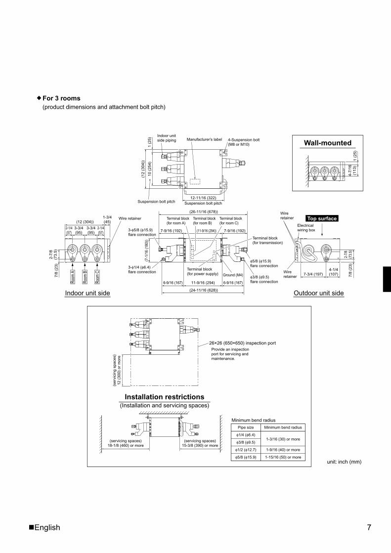
Installation• This unit may be installed suspended from the ceiling or mounted on the wall.• Be sure to install the unit with the top surface facing upward as shown in the diagram.• Be sure to leave a 26 inch (650mm) square opening for maintenance and inspection as shown in the diagram below, for both
ceiling-suspended installation and wall-mounted installation.• This unit “does not require drain treatment”.• The inclination of top surface must be within ±5 degrees forward or back or to the sides.
(product dimensions and attachment bolt pitch)
1 (2
5)4-
7/16
(113
)
Wall-mounted
1-3/4(45)
2-1/4(57)
3-3/4(95)
(12 (304))
2-7/
8(7
3.5)
7/8
(23)
Room
A
Room
B
Indoor unit side Outdoor unit side
Wire retainer
(7-1
/16
(180
))
(24-11/16 (628))
11-9/16 (294) 6-9/16 (167)
7-3/4 (197)4-1/4(107)
12-11/16 (322)Suspension bolt pitch
(26-11/16 (678))
10 (
254)
(12
(304
))
1 (2
5)
2-7/
8(7
3.5)
6-9/16 (167)
2-φ5/8 (φ15.9) flare connection
2-φ1/4 (φ6.4) flare connection
Terminal block(for power supply)
Terminal block (for room A)
Terminal block (for room B)
Terminal block (for transmission)
φ3/8 (φ9.5) flare connection
φ5/8 (φ15.9) flare connection
Ground (M4) 7/8
(23)
Suspension bolt pitch
Manufacturer’s label 4-Suspension bolt (M8 or M10)
For 2 rooms
Indoor unit side piping
Top surfaceElectrical wiring box
Wire retainer
Wire retainer
7-9/16 (192) (11-9/16 (294)) 7-9/16 (192)
Installation restrictions(Installation and servicing spaces)
26×26 (650×650) inspection portProvide an inspection port for servicing and maintenance.
(ser
vici
ng s
pace
s)12
(30
0) o
r m
ore
(servicing spaces)15-3/8 (390) or more
(servicing spaces)15-3/8 (390) or more
Minimum bend radius
Minimum bend radiusPipe size
φ1/4 (φ6.4)1-3/16 (30) or more
φ3/8 (φ9.5)
1-15/16 (50) or moreφ5/8 (φ15.9)
1-9/16 (40) or moreφ1/2 (φ12.7)
unit: inch (mm)
01_EN_3P329626-1.fm Page 6 Friday, November 9, 2012 11:10 AM
English 7
(product dimensions and attachment bolt pitch)For 3 rooms
Wall-mounted
26×26 (650×650) inspection portProvide an inspection port for servicing and maintenance.
1-3/4(45)
2-1/4(57)
2-1/4(57)
3-3/4(95)
3-3/4(95)
(12 (304))
2-7/
8(7
3.5)
7/8
(23)
Room
A
Room
B
Room
C
Indoor unit side Outdoor unit side
Wire retainer
(7-1
/16
(180
))
(26-11/16 (678))
(24-11/16 (628))
11-9/16 (294) 6-9/16 (167)
7-3/4 (197)4-1/4(107)
12-11/16 (322)
10 (
254)
(12
(304
))
1 (2
5)
2-7/
8(7
3.5)
7/8
(23)
6-9/16 (167)
Terminal block(for power supply)
Terminal block (for transmission)
φ3/8 (φ9.5) flare connection
φ5/8 (φ15.9) flare connection
Ground (M4)
Top surface
Suspension bolt pitch
Indoor unit side piping
Suspension bolt pitch
Manufacturer’s label 4-Suspension bolt (M8 or M10)
1 (2
5)4-
7/16
(113
)
Electrical wiring box
Wire retainer
Wire retainer
3-φ5/8 (φ15.9) flare connection
3-φ1/4 (φ6.4) flare connection
Terminal block (for room A)
Terminal block (for room C)
Terminal block (for room B)
7-9/16 (192) (11-9/16 (294)) 7-9/16 (192)
(ser
vici
ng s
pace
s)12
(30
0) o
r m
ore
(servicing spaces)18-1/8 (460) or more
(servicing spaces)15-3/8 (390) or more
Installation restrictions(Installation and servicing spaces)
Minimum bend radius
Minimum bend radiusPipe size
φ1/4 (φ6.4)1-3/16 (30) or more
φ3/8 (φ9.5)
1-15/16 (50) or moreφ5/8 (φ15.9)
1-9/16 (40) or moreφ1/2 (φ12.7)
unit: inch (mm)
01_EN_3P329626-1.fm Page 7 Friday, November 9, 2012 11:10 AM
8 English
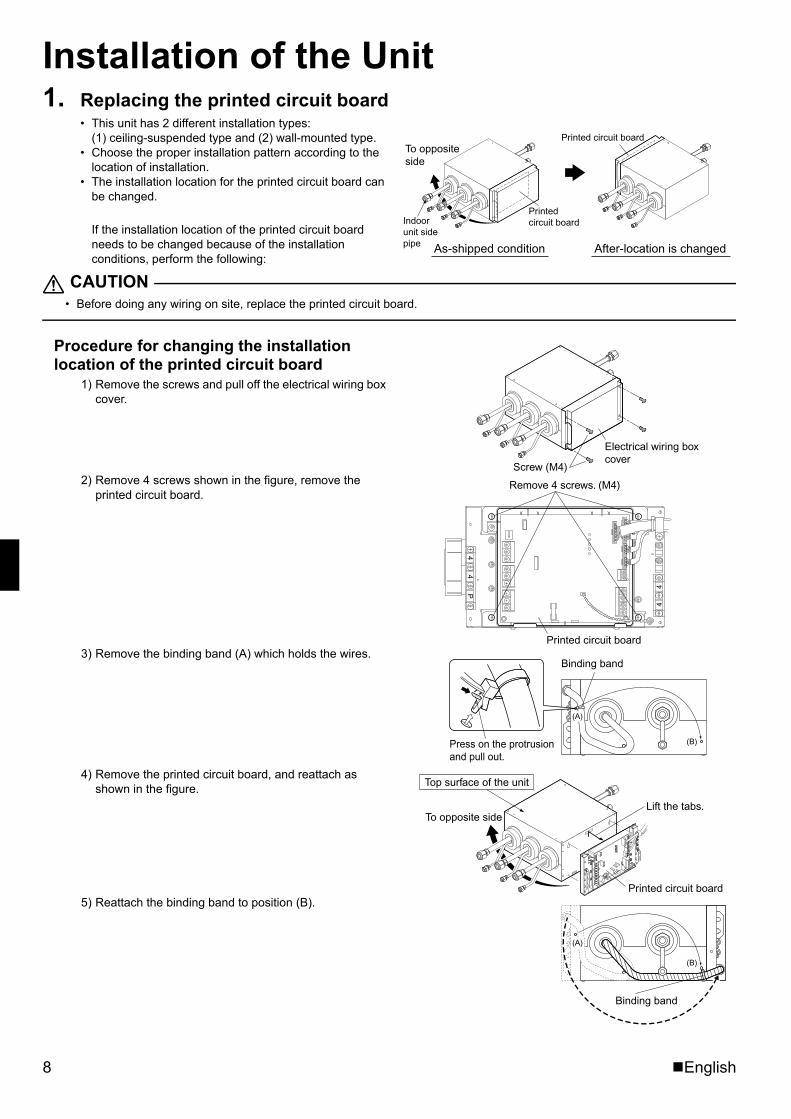
Installation of the Unit1. Replacing the printed circuit board
• This unit has 2 different installation types: (1) ceiling-suspended type and (2) wall-mounted type.
• Choose the proper installation pattern according to the location of installation.
• The installation location for the printed circuit board can be changed.
If the installation location of the printed circuit board needs to be changed because of the installation conditions, perform the following:
CAUTION• Before doing any wiring on site, replace the printed circuit board.
Procedure for changing the installation location of the printed circuit board
1) Remove the screws and pull off the electrical wiring box cover.
2) Remove 4 screws shown in the figure, remove the printed circuit board.
3) Remove the binding band (A) which holds the wires.
4) Remove the printed circuit board, and reattach as shown in the figure.
5) Reattach the binding band to position (B).
Printed circuit board
Printed circuit board
As-shipped condition After-location is changed
Indoor unit side pipe
To opposite side
Screw (M4)
Electrical wiring box cover
44
P
44
Remove 4 screws. (M4)
Printed circuit board
Binding band
Press on the protrusion and pull out.
(A)
(B)
Printed circuit board
Lift the tabs.To opposite side
Top surface of the unit
(A)
(B)
Binding band
01_EN_3P329626-1.fm Page 8 Friday, November 9, 2012 11:10 AM
English 9
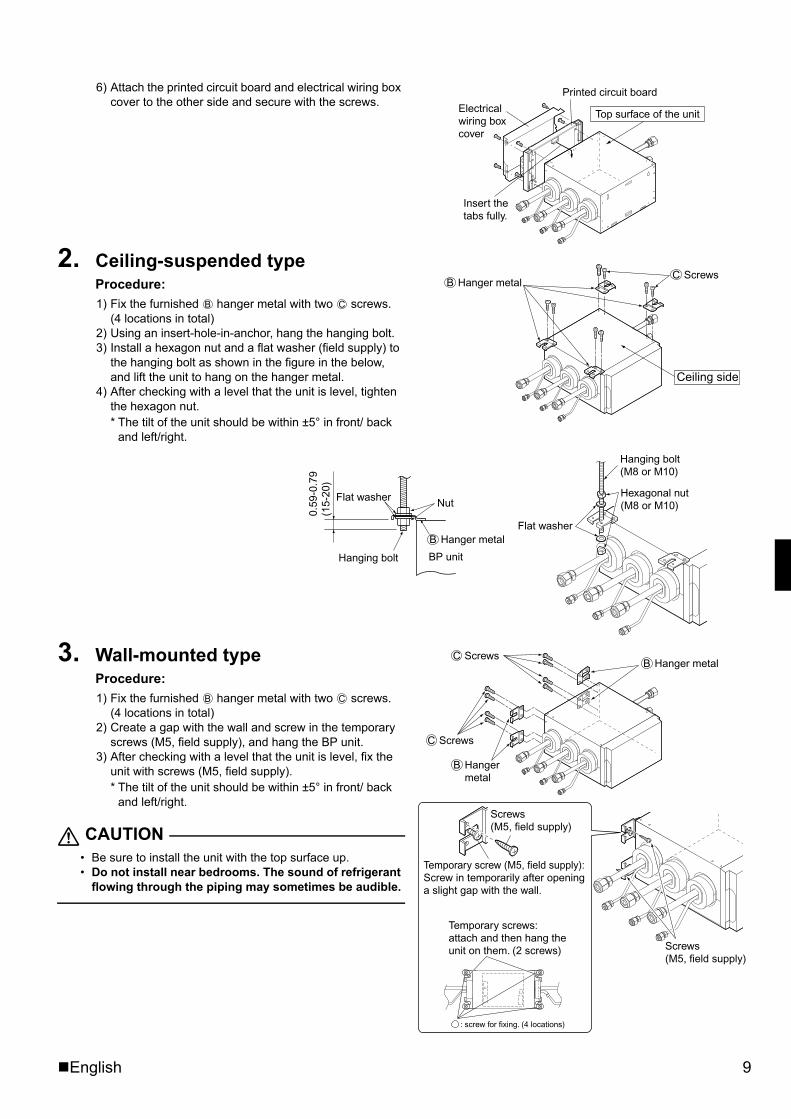
6) Attach the printed circuit board and electrical wiring box cover to the other side and secure with the screws.
2. Ceiling-suspended type Procedure: 1) Fix the furnished hanger metal with two screws.
(4 locations in total)2) Using an insert-hole-in-anchor, hang the hanging bolt.3) Install a hexagon nut and a flat washer (field supply) to
the hanging bolt as shown in the figure in the below, and lift the unit to hang on the hanger metal.
4) After checking with a level that the unit is level, tighten the hexagon nut.* The tilt of the unit should be within ±5° in front/ back
and left/right.
3. Wall-mounted type Procedure:1) Fix the furnished hanger metal with two screws.
(4 locations in total)2) Create a gap with the wall and screw in the temporary
screws (M5, field supply), and hang the BP unit. 3) After checking with a level that the unit is level, fix the
unit with screws (M5, field supply).* The tilt of the unit should be within ±5° in front/ back
and left/right.
CAUTION• Be sure to install the unit with the top surface up.• Do not install near bedrooms. The sound of refrigerant
flowing through the piping may sometimes be audible.
Electrical wiring box cover
Insert the tabs fully.
Printed circuit board
Top surface of the unit
Ceiling side
ScrewsCHanger metalB
B C
Flat washer
0.59
-0.7
9 (1
5-20
)
Hanging bolt
Nut
BP unit
Hanging bolt(M8 or M10)
Hexagonal nut(M8 or M10)
Flat washerHanger metalB
Screws(M5, field supply)
Screws(M5, field supply)
Temporary screws: attach and then hang the unit on them. (2 screws)
: screw for fixing. (4 locations)
Temporary screw (M5, field supply): Screw in temporarily after opening a slight gap with the wall.
ScrewsC
ScrewsC
Hanger metalB
Hanger metal
B
B C
01_EN_3P329626-1.fm Page 9 Friday, November 9, 2012 11:10 AM
10 English
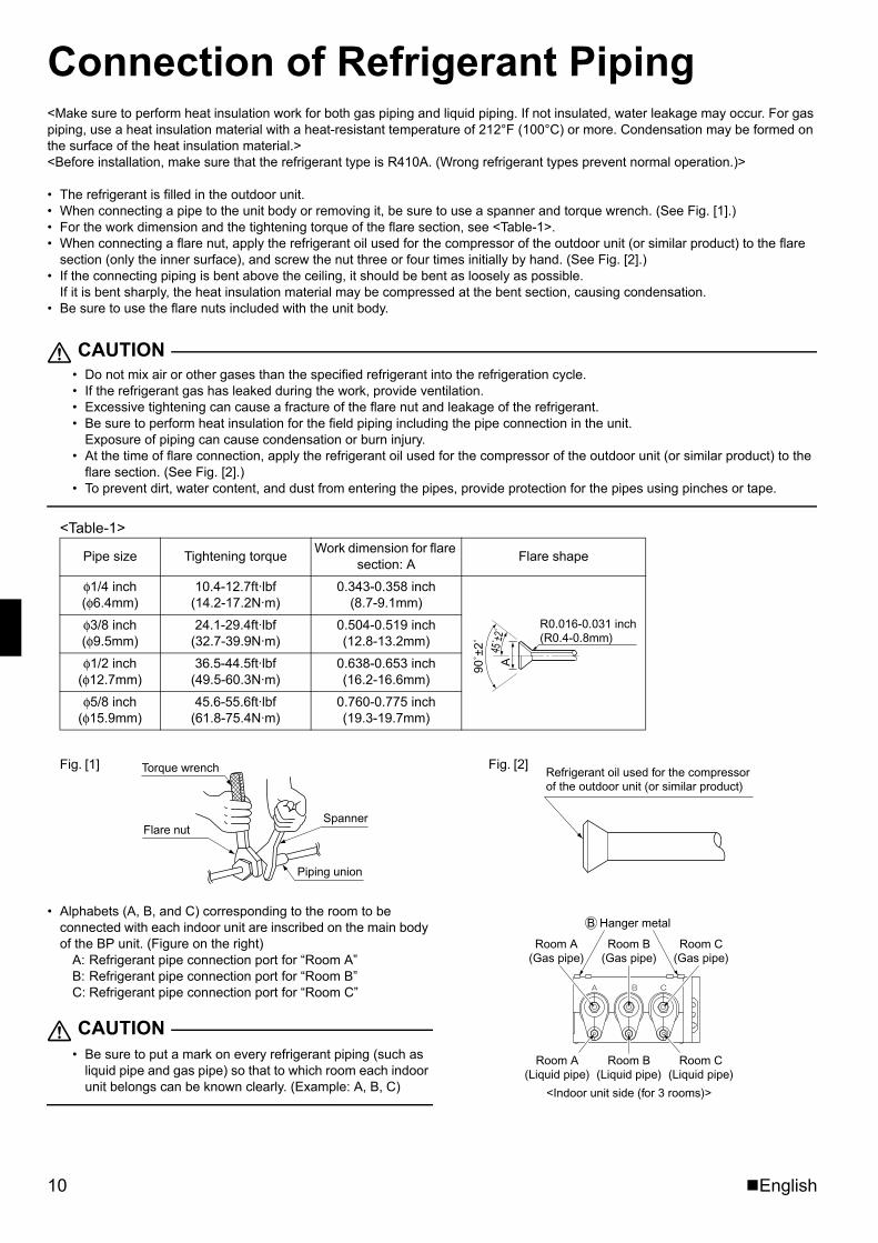
Connection of Refrigerant Piping<Make sure to perform heat insulation work for both gas piping and liquid piping. If not insulated, water leakage may occur. For gas piping, use a heat insulation material with a heat-resistant temperature of 212°F (100°C) or more. Condensation may be formed on the surface of the heat insulation material.><Before installation, make sure that the refrigerant type is R410A. (Wrong refrigerant types prevent normal operation.)>
• The refrigerant is filled in the outdoor unit.• When connecting a pipe to the unit body or removing it, be sure to use a spanner and torque wrench. (See Fig. [1].)• For the work dimension and the tightening torque of the flare section, see <Table-1>.• When connecting a flare nut, apply the refrigerant oil used for the compressor of the outdoor unit (or similar product) to the flare
section (only the inner surface), and screw the nut three or four times initially by hand. (See Fig. [2].)• If the connecting piping is bent above the ceiling, it should be bent as loosely as possible.
If it is bent sharply, the heat insulation material may be compressed at the bent section, causing condensation.• Be sure to use the flare nuts included with the unit body.
CAUTION• Do not mix air or other gases than the specified refrigerant into the refrigeration cycle.• If the refrigerant gas has leaked during the work, provide ventilation.• Excessive tightening can cause a fracture of the flare nut and leakage of the refrigerant.• Be sure to perform heat insulation for the field piping including the pipe connection in the unit.
Exposure of piping can cause condensation or burn injury.• At the time of flare connection, apply the refrigerant oil used for the compressor of the outdoor unit (or similar product) to the
flare section. (See Fig. [2].)• To prevent dirt, water content, and dust from entering the pipes, provide protection for the pipes using pinches or tape.
<Table-1>
• Alphabets (A, B, and C) corresponding to the room to be connected with each indoor unit are inscribed on the main body of the BP unit. (Figure on the right)
A: Refrigerant pipe connection port for “Room A” B: Refrigerant pipe connection port for “Room B” C: Refrigerant pipe connection port for “Room C”
CAUTION• Be sure to put a mark on every refrigerant piping (such as
liquid pipe and gas pipe) so that to which room each indoor unit belongs can be known clearly. (Example: A, B, C)
Pipe size Tightening torque Work dimension for flare section: A Flare shape
φ1/4 inch(φ6.4mm)
10.4-12.7ft·lbf(14.2-17.2N·m)
0.343-0.358 inch(8.7-9.1mm)
φ3/8 inch(φ9.5mm)
24.1-29.4ft·lbf(32.7-39.9N·m)
0.504-0.519 inch(12.8-13.2mm)
φ1/2 inch(φ12.7mm)
36.5-44.5ft·lbf(49.5-60.3N·m)
0.638-0.653 inch(16.2-16.6mm)
φ5/8 inch(φ15.9mm)
45.6-55.6ft·lbf(61.8-75.4N·m)
0.760-0.775 inch(19.3-19.7mm)
A45
˚±2˚
90˚±
2˚
R0.016-0.031 inch(R0.4-0.8mm)
Torque wrench
Flare nutSpanner
Piping union
Fig. [1] Fig. [2]Refrigerant oil used for the compressor of the outdoor unit (or similar product)
Room B(Gas pipe)
Room A(Gas pipe)
Room C(Gas pipe)
Room B(Liquid pipe)
<Indoor unit side (for 3 rooms)>
Room C(Liquid pipe)
Room A(Liquid pipe)
Hanger metalB
01_EN_3P329626-1.fm Page 10 Friday, November 9, 2012 11:10 AM
English 11
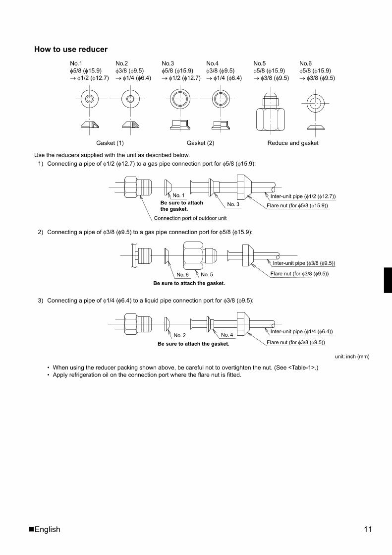
How to use reducer
Use the reducers supplied with the unit as described below.1) Connecting a pipe of φ1/2 (φ12.7) to a gas pipe connection port for φ5/8 (φ15.9):
2) Connecting a pipe of φ3/8 (φ9.5) to a gas pipe connection port for φ5/8 (φ15.9):
3) Connecting a pipe of φ1/4 (φ6.4) to a liquid pipe connection port for φ3/8 (φ9.5):
• When using the reducer packing shown above, be careful not to overtighten the nut. (See <Table-1>.)• Apply refrigeration oil on the connection port where the flare nut is fitted.
Gasket (1)
No.1�5/8 (�15.9)� �1/2 (�12.7)
No.2�3/8 (�9.5)� �1/4 (�6.4)
No.3�5/8 (�15.9)� �1/2 (�12.7)
No.5�5/8 (�15.9)� �3/8 (�9.5)
No.6�5/8 (�15.9)� �3/8 (�9.5)
No.4�3/8 (�9.5)� �1/4 (�6.4)
Gasket (2) Reduce and gasket
Connection port of outdoor unit
No. 1Be sure to attach the gasket.
No. 3 Flare nut (for �5/8 (�15.9))
Inter-unit pipe (�1/2 (�12.7))
Flare nut (for �3/8 (�9.5))
Inter-unit pipe (�3/8 (�9.5))
No. 5No. 6
Be sure to attach the gasket.
Inter-unit pipe (�1/4 (�6.4))
Flare nut (for �3/8 (�9.5))Be sure to attach the gasket.
No. 2 No. 4
unit: inch (mm)
01_EN_3P329626-1.fm Page 11 Friday, November 9, 2012 11:10 AM
12 English
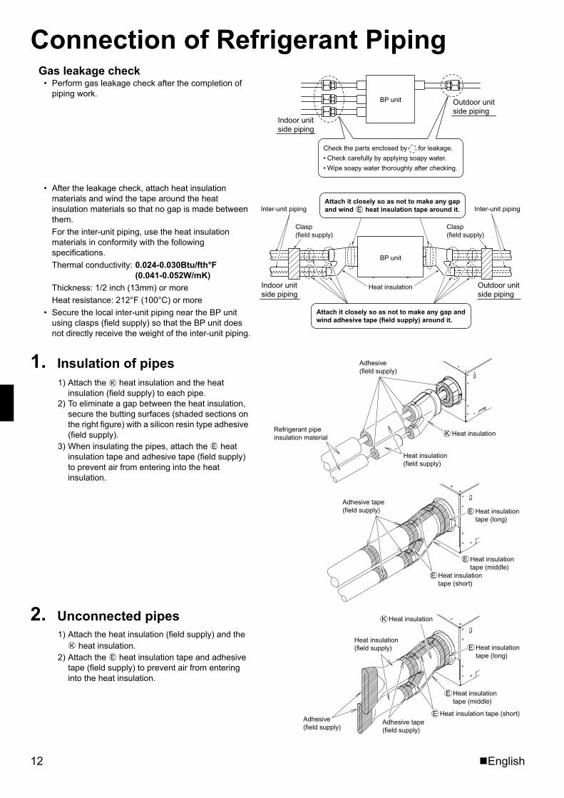
Connection of Refrigerant PipingGas leakage check
• Perform gas leakage check after the completion of piping work.
• After the leakage check, attach heat insulation materials and wind the tape around the heat insulation materials so that no gap is made between them. For the inter-unit piping, use the heat insulation materials in conformity with the following specifications. Thermal conductivity: 0.024-0.030Btu/fth°F
(0.041-0.052W/mK)Thickness: 1/2 inch (13mm) or moreHeat resistance: 212°F (100°C) or more
• Secure the local inter-unit piping near the BP unit using clasps (field supply) so that the BP unit does not directly receive the weight of the inter-unit piping.
1. Insulation of pipes 1) Attach the heat insulation and the heat
insulation (field supply) to each pipe.2) To eliminate a gap between the heat insulation,
secure the butting surfaces (shaded sections on the right figure) with a silicon resin type adhesive (field supply).
3) When insulating the pipes, attach the heat insulation tape and adhesive tape (field supply) to prevent air from entering into the heat insulation.
2. Unconnected pipes 1) Attach the heat insulation (field supply) and the
heat insulation.2) Attach the heat insulation tape and adhesive
tape (field supply) to prevent air from entering into the heat insulation.
BP unit
Indoor unit side piping
Outdoor unit side piping
Check the parts enclosed by for leakage.
• Check carefully by applying soapy water.
• Wipe soapy water thoroughly after checking.
Inter-unit piping
Clasp(field supply)
Indoor unit side piping
Heat insulation
Attach it closely so as not to make any gap and wind E heat insulation tape around it.
Clasp(field supply)
Inter-unit piping
Outdoor unit side piping
Attach it closely so as not to make any gap and wind adhesive tape (field supply) around it.
BP unit
E
Adhesive (field supply)
Heat insulation tape (short)
E
Refrigerant pipe insulation material
Heat insulation (field supply)
Heat insulationK
Heat insulation tape (middle)
E
Heat insulation tape (long)
EAdhesive tape (field supply)
K
E
Heat insulationK
Heat insulation (field supply)
Adhesive (field supply)
Heat insulation tape (short)EAdhesive tape (field supply)
Heat insulation tape (middle)
E
Heat insulation tape (long)
EK
E
01_EN_3P329626-1.fm Page 12 Friday, November 9, 2012 11:10 AM
English 13
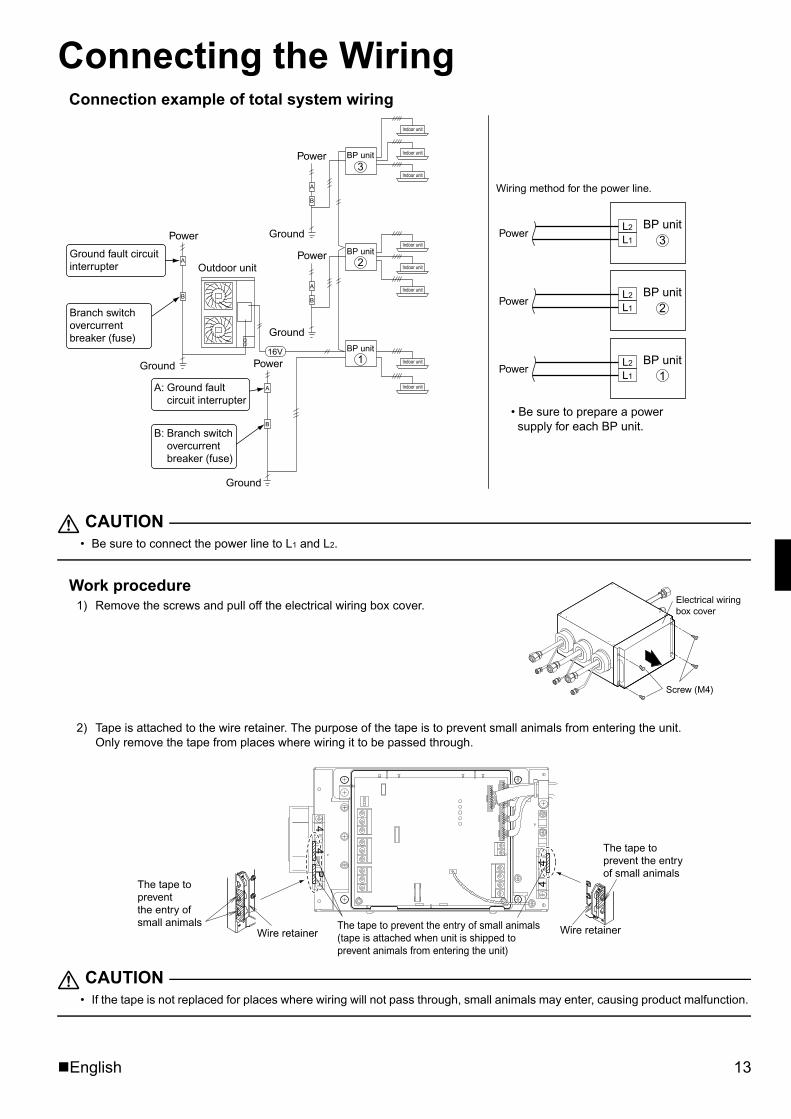
Connecting the WiringConnection example of total system wiring
CAUTION• Be sure to connect the power line to L1 and L2.
Work procedure 1) Remove the screws and pull off the electrical wiring box cover.
2) Tape is attached to the wire retainer. The purpose of the tape is to prevent small animals from entering the unit. Only remove the tape from places where wiring it to be passed through.
CAUTION• If the tape is not replaced for places where wiring will not pass through, small animals may enter, causing product malfunction.
16VL2
L1
L2
L1
L2
L1
B
A
B
A
A
B
A
B
Power
Ground
Outdoor unit
Power
Ground
BP unit
Indoor unit
Indoor unit
Indoor unit
Indoor unit
Indoor unit
Indoor unit
Indoor unit
Indoor unit
BP unit
BP unit
Wiring method for the power line.
Power
Power
Power
• Be sure to prepare a power supply for each BP unit.
BP unit3
BP unit2
BP unit1
Power
Ground
Power
Ground
3
2
1
Ground fault circuit interrupter
Branch switch overcurrent breaker (fuse)
A: Ground fault circuit interrupter
B: Branch switch overcurrent breaker (fuse)
Screw (M4)
Electrical wiring box cover
44
44
P
The tape to prevent the entry of small animals (tape is attached when unit is shipped to prevent animals from entering the unit)
Wire retainer
The tape to prevent the entry of small animals
The tape to prevent the entry of small animals
Wire retainer
01_EN_3P329626-1.fm Page 13 Friday, November 9, 2012 11:10 AM
14 English
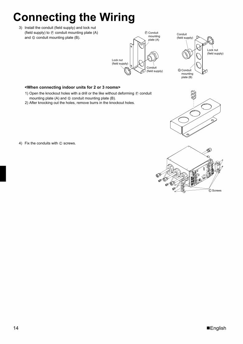
Connecting the Wiring3) Install the conduit (field supply) and lock nut
(field supply) to conduit mounting plate (A) and conduit mounting plate (B).
<When connecting indoor units for 2 or 3 rooms> 1) Open the knockout holes with a drill or the like without deforming conduit
mounting plate (A) and conduit mounting plate (B).2) After knocking out the holes, remove burrs in the knockout holes.
4) Fix the conduits with screws.
Conduit (field supply)
Lock nut (field supply)
Lock nut (field supply)
Conduit (field supply) Conduit
mounting plate (B)
G
Conduit mounting plate (A)
FF
G
F
G
ScrewsC
C
01_EN_3P329626-1.fm Page 14 Friday, November 9, 2012 11:10 AM
English 15
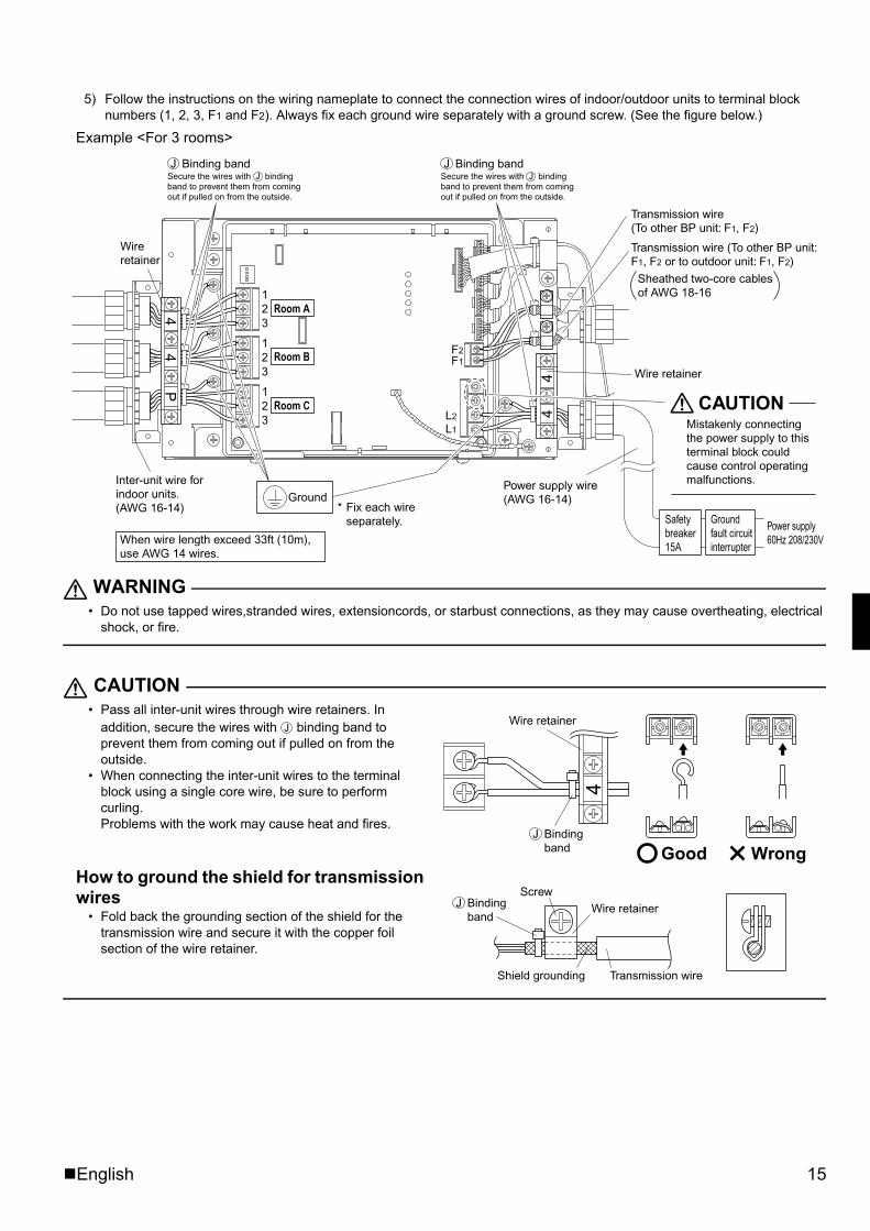
5) Follow the instructions on the wiring nameplate to connect the connection wires of indoor/outdoor units to terminal block numbers (1, 2, 3, F1 and F2). Always fix each ground wire separately with a ground screw. (See the figure below.)
Example <For 3 rooms>
WARNING• Do not use tapped wires,stranded wires, extensioncords, or starbust connections, as they may cause overtheating, electrical
shock, or fire.
CAUTION• Pass all inter-unit wires through wire retainers. In
addition, secure the wires with binding band to prevent them from coming out if pulled on from the outside.
• When connecting the inter-unit wires to the terminal block using a single core wire, be sure to perform curling. Problems with the work may cause heat and fires.
How to ground the shield for transmission wires
• Fold back the grounding section of the shield for the transmission wire and secure it with the copper foil section of the wire retainer.
F1F2
L2
L1
44
44
P
Wire retainer
Inter-unit wire for indoor units.(AWG 16-14)
When wire length exceed 33ft (10m), use AWG 14 wires.
Power supply wire (AWG 16-14)
Wire retainer
21
3
21
3
21
3Room A
Room B
Room C
Ground
Safety breaker 15A
Ground fault circuitinterrupter
Power supply 60Hz 208/230V
Secure the wires with J binding band to prevent them from coming out if pulled on from the outside.
Transmission wire (To other BP unit: F1, F2)
Transmission wire (To other BP unit: F1, F2 or to outdoor unit: F1, F2)
* Fix each wire separately.
CAUTIONMistakenly connecting the power supply to this terminal block could cause control operating malfunctions.
Sheathed two-core cables of AWG 18-16
Binding bandJJSecure the wires with J binding
band to prevent them from coming out if pulled on from the outside.
Binding bandJJ
4
Good Wrong
Wire retainer
Binding band
J
J
Screw
Shield grounding Transmission wire
Wire retainerBinding band
J
01_EN_3P329626-1.fm Page 15 Friday, November 9, 2012 11:10 AM
16 English
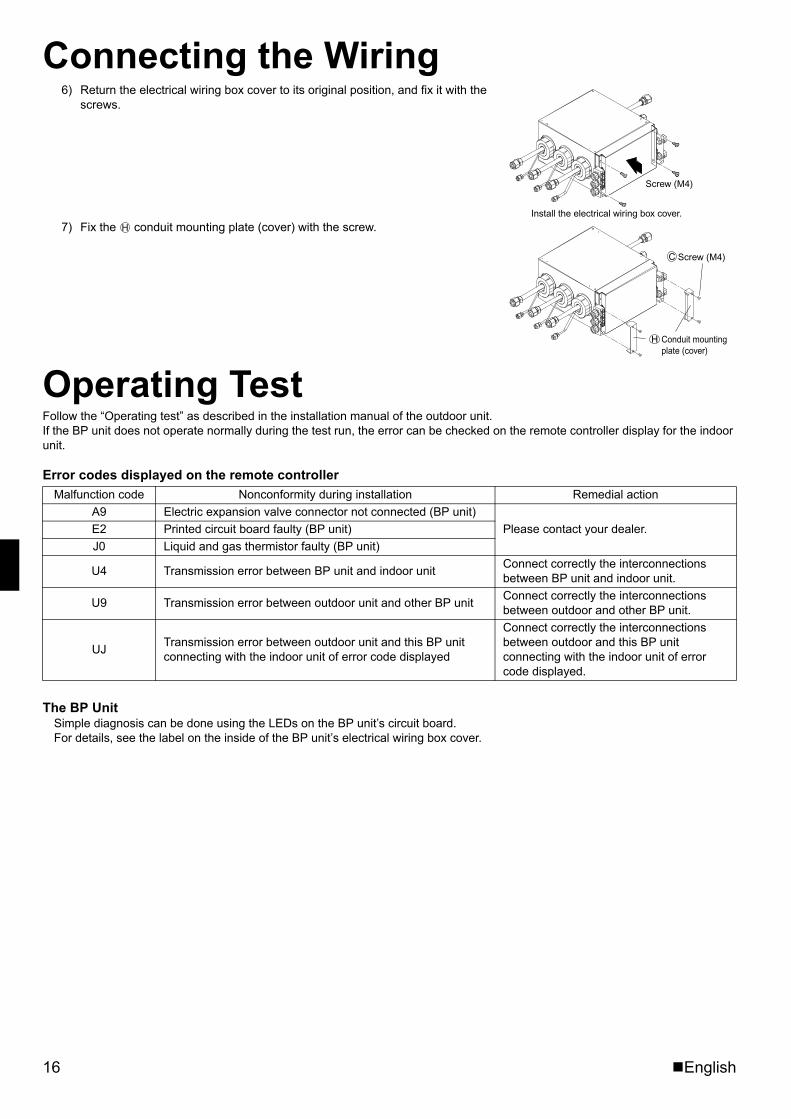
Connecting the Wiring6) Return the electrical wiring box cover to its original position, and fix it with the
screws.
7) Fix the conduit mounting plate (cover) with the screw.
Operating TestFollow the “Operating test” as described in the installation manual of the outdoor unit. If the BP unit does not operate normally during the test run, the error can be checked on the remote controller display for the indoor unit.
Error codes displayed on the remote controller
The BP UnitSimple diagnosis can be done using the LEDs on the BP unit’s circuit board. For details, see the label on the inside of the BP unit’s electrical wiring box cover.
Malfunction code Nonconformity during installation Remedial actionA9 Electric expansion valve connector not connected (BP unit)
Please contact your dealer.E2 Printed circuit board faulty (BP unit)J0 Liquid and gas thermistor faulty (BP unit)
U4 Transmission error between BP unit and indoor unit Connect correctly the interconnections between BP unit and indoor unit.
U9 Transmission error between outdoor unit and other BP unit Connect correctly the interconnections between outdoor and other BP unit.
UJ Transmission error between outdoor unit and this BP unit connecting with the indoor unit of error code displayed
Connect correctly the interconnections between outdoor and this BP unit connecting with the indoor unit of error code displayed.
Screw (M4)
Install the electrical wiring box cover.
Screw (M4)
Conduit mounting plate (cover)
H
C
H
01_EN_3P329626-1.fm Page 16 Friday, November 9, 2012 11:10 AM

(1211) HT3P329626-1 M12B277Two-dimensional bar code is a code for manufacturing.
00_CV_3P329626-1.fm Page 2 Thursday, November 8, 2012 11:52 AM