00 COVER & TOC... · Chapter 1 Safety Information Page 1 - 1 80101253 Rev 02 The following safety...
38
Rev. 03 80115501 EO 5656A WZ-44/55Z SERIES Installation Instructions 4400 & 5500 lb. Capacity GR01352 ATTENTION THE SUCCESS OR FAILURE OF THIS EQUIPMENT COULD VERY WELL DEPEND ON THOROUGH AND PROPER INSTALLATION. READ AND UNDERSTAND THE CONTENTS OF THESE INSTRUCTIONS BEFORE PROCEEDING. IMPORTANT WHEN INSTALLED, THIS LIFT MUST NOT ALTER OR PREVENT VEHICLE COMPLIANCE TO ANY EXISTING STATE OR FEDERAL STANDARDS. EACH CHASSIS MANUFACTURER’S RECOMMENDATIONS SHOULD BE CONSULTED FOR COMPLIANCE. 12-05 OHIO 285 Northeast Avenue Tallmadge, OH 44278 (330) 633-9191 FAX – (330) 633-1418 GEORGIA 1395 N. Cobb Parkway Marietta, GA 30062 (770) 425-0922 FAX – (770) 425-5886 CALIFORNIA 227 E. Compton Blvd Gardena CA 90248 (310) 243-6800 FAX – (310) 538-1136 Visit us at www.waltco.com
Transcript of 00 COVER & TOC... · Chapter 1 Safety Information Page 1 - 1 80101253 Rev 02 The following safety...

Rev. 03 80115501 EO 5656A
WZ-44/55Z SERIES Installation Instructions 4400 & 5500 lb. Capacity
GR01352
ATTENTION THE SUCCESS OR FAILURE OF THIS EQUIPMENT COULD
VERY WELL DEPEND ON THOROUGH AND PROPER
INSTALLATION.
READ AND UNDERSTAND THE CONTENTS OF THESE
INSTRUCTIONS BEFORE PROCEEDING.
IMPORTANT WHEN INSTALLED, THIS LIFT
MUST NOT ALTER OR PREVENT VEHICLE
COMPLIANCE TO ANY EXISTING STATE OR
FEDERAL STANDARDS.
EACH CHASSIS MANUFACTURER’S
RECOMMENDATIONS SHOULD BE CONSULTED
FOR COMPLIANCE.
12-05
OHIO 285 Northeast Avenue Tallmadge, OH 44278 (330) 633-9191 FAX – (330) 633-1418
GEORGIA 1395 N. Cobb Parkway Marietta, GA 30062 (770) 425-0922 FAX – (770) 425-5886
CALIFORNIA 227 E. Compton Blvd Gardena CA 90248 (310) 243-6800 FAX – (310) 538-1136
Visit us at www.waltco.com

Rev. 03 80115501 EO 5656A
Table of Contents Chapter
ATTENTION SAFETY INFORMATION ---------------------------- --------------- 1 LIFTGATE TERMINOLOGY ------------------------ --------------- 2 BASIC MOUNTING REQUIREMENTS ----------- --------------- 3 INSTALLATION ---------------------------------------- --------------- 4 PLACEMENT OF DECALS ------------------------- --------------- 5 LUBRICATION INSTRUCTIONS ----------------- --------------- 6 FINAL INSPECTION --------------------------------- --------------- 7 SERVICE BULLETINS & TROUBLESHOOTING

INTRODUCTION
If anyone observes improper installation, improper operation, or damage, they should immediately contact a qualified person for assistance and correction. We strongly urge anyone that has any questions or doubts as to the installation, condition, use, operation, maintenance or repair of the liftgate to contact us at Waltco where we have qualified personnel that will be happy to assist you. Telephone numbers and addresses of these locations are listed in the Owners Manual and Installation Instructions. INSTALLATION
Waltco liftgates should only be installed by those with sufficient basic skills to understand the installation and operation of the liftgate, along with the equipment on which the liftgate is being installed. Waltco’s installation instructions are not intended to give rationale for all the instructions that are given; however, it is the intent of these instructions to give the installer both the operations and what we believe to be the most desirable sequence of implementing these operations. These instructions can in no way expand into an area where they will replace a qualified person, or clear thinking and a basic knowledge that must be possessed by the installer.
It has been our experience that a knowledgeable journeyman following these instructions and observing the operation of the liftgate will have a sufficient comprehension of the liftgate to enable this person to troubleshoot and correct all normal problems that may be encountered.
Failure to follow the installation instructions, adjustments and mounting dimensions may result in improper and unsafe operation of the liftgate. Unauthorized alterations of the liftgate can cause an undesirable and dangerous condition. OWNERS MANUAL
The Waltco Owners Manual is intended to act as a guide for operation and routine maintenance but is no way intended to encourage usage or repair of the liftgate by those who are not qualified to do so.
The contents of the owners manual include, but are not limited to general operation instructions, routine lubrication, parts lists, and an outline of things that should be checked but may not be obvious to those not technically qualified. This manual assumes the liftgate is properly installed, undamaged and operates correctly. Improper installation, improper operation, or damage should be immediately corrected by a qualified person. INSPECTION
As part of the regular inspection of a liftgate and after damage or suspicion of an overload, inspect for wear or structural damage and make necessary repairs or replacements. Check all structural components and their attachment to the liftgate for cracked welds, wear and part deformation. Check cylinder and hose for leaks. Inspections and repairs should be made by a qualified mechanic. REPLACEMANT PARTS
Use only Waltco original equipment replacement parts. Components of other liftgate manufacturers may outwardly appear to be the same but are not interchangeable with Waltco products. Waltco components are specifically designed for safety requirements, reliability and compatibility with our products. Refer to your Waltco parts manual when ordering parts. NOTE: When ordering, give model and serial number of liftgate. DECALS
It is important that every vehicle that has a WALTCO Liftgate have legible DECALS clearly posted on the vehicle and an OWNER’S MANUAL in the vehicle at all times as a guide for proper operation and maintenance.
Additional DECALS and OWNER’S MANUALS can be obtained from WALTCO TRUCK EQUIPMENT COMPANY. 80101388 Rev 01

Chapter 1 Safety Information
Page 1 - 1 80101253 Rev 02
The following safety information must be read before operating Waltco liftgates. • Read and understand the Owner’s Manual and all decals on liftgate before operating
liftgate. • Do not operate liftgate without a thorough knowledge and understanding of the operation of
the liftgate. • Liftgate hazards can result in crushing or falling • This liftgate is designed for loading and unloading of cargo. If personnel are required to ride
liftgate, observe and familiarize yourself with the liftgate operation, decals and manuals. Ensure stable footing at all times
• Do not ride liftgate with unstable loads. • Keep hands and feet clear of all potential pinch points. • Do not attempt any repairs unless you are qualified to do so. Care should be taken when
work is performed on a disabled liftgate located near moving traffic. When possible the vehicle should be moved away from traffic areas for repair. Precautionary measures should be taken to ensure personal safety including those recommended in Federal Motor Vehicle Safety Standards 571.125.
• NEVER OVERLOAD LIFTGATE Refer to the Explanation of Specification Tag in the Liftgate Terminology chapter for liftgate capacity rating.
• Never use liftgate if it makes any unusual noise, has unusual vibration, raises or lowers unevenly, or fails to operate smoothly.
• Never use liftgate if it shows any signs of structural damage such as cracked welds, bent or distorted members.
• For liftgates with Runners, never use liftgate if Runners do not travel freely and smoothly. • All protective covers, guards, and safety devices must be in place and access doors closed
before operating liftgate. • Make certain the Platform area, including the area in which loads may fall, is clear before
and at all times during the operation of the liftgate. • For liftgates with Roller Lifting Chain, the Chain should be replaced every (5) five years or
15,000 cycles, whichever comes first. Replace only with Waltco approved Roller Chain. • A Lock-Out device or Shut-Off Switch should always be used to prevent unauthorized use
of liftgate. • Never transfer loads which exceed lifting capacity on or over any part of the Platform
unless the liftgate is equipped with a special reinforced Platform and Platform Support Bars for use when the Platform is used as loading ramp (dock board). Refer to the “Using Platform as a loading ramp” Chapter in the Operation Instructions of the BZ/RZ series Owner’s Manual.
• Platform is always to be properly stored and secured for transit. See the Owner’s Manual for details.
• For liftgates equipped with Trailer Hitches, never exceed the rated capacity of the hitch. Do not exceed the vehicle’s weight rating. Refer to the vehicle’s Owner’s Manual.

Chapter 1 Safety Information
Page 1 - 2 80101253 Rev 02
• Take care to retain cargo during transit for liftgate Platforms which function as the tailgate
or door of the cargo area. Small objects can fall through the space between the vehicle and the folded Platform.
• Vehicle must comply with all state and federal standards. • Follow the “Maintenance Guide” chapter in the Owner’s Manual. Liftgates with Tilt Function • Proper use of the Control Switches is of extreme importance. • Improper use of Tilt Switch could cause load to fall from the Platform or damage the liftgate. • Platform should be in a generally horizontal position when raising or lowering with a load. • In any tilt position, the Platform may vary from level while raising or lowering the Platform. Liftgates equipped with spring operated Cam Closer • Replace Cam Release Spring every five (5) years or 15,000 cycles, whichever comes first. RGL • Make certain Platform Brake mechanisms are operating properly. • The Runners are always to remain powered up against the Upstops Pins when in transit. • Inspect Cables every three (3) months or 750 cycles, whichever comes first. Cables must
be replaced if they show signs of wear, distortion, kinking or if any broken wires are visible • Replace cables every five (5) years or 10,000 cycles, whichever comes first. SIGNAL WORDS
WARNING Indicates a potentially hazardous situation, which if not avoided, could result in death or serious injury. Black letters on an orange background CAUTION Indicates a potentially hazardous situation, which if not avoided, may result in minor or moderate injury. May also be used to alert against unsafe practices. Black letters on a yellow background.
WARNING
CAUTION

Chapter 2 Liftgate Terminology
Page 2-1
1. Platform 2. Mount tube 3. Lift arm 4. Lift cylinder 5. Tilt cylinder, driver side 6. Tilt cylinder, curb side 7. Pump unit (inside mount tube) 8. Slide tube, driver side 9. Slide tube, curb side
GR00448
1
5
4
3
6
2
7
9
8

Chapter 2 Liftgate Terminology
Page 2-2
EXPLANATION OF SPECIFICATION TAG MODEL NO. MODEL NAME DESCRIPTION CAPACITY
154 WZ-44Z LEVEL LIFT 4400 LBS. 155 WZ-55Z LEVEL LIFT 5500 LBS.
MODEL NUMBER RATED CAPACITY
Based on an evenlydistributed load on theplatform flat surface
SERIAL NUMBERof Liftgate. To be usedwhen ordering parts orwhen contacting Waltcofor service or warranty.
DATE OFMANUFACTUREMONTH/YEAR
GR00053

Chapter 3 Basic Mounting Requirements
Page 3-1
DETERMINE MOUNTING DIMENSIONS
Determine bed height. Measure from top of vehicle floor down to ground.
Verify which length arms liftgate has.
NOTE: All dimensions when vehicle unloaded on horizontal surface.
IMPORTANT! Do not exceed given A- dimension or max bed height. This can cause damage to liftgate and improper operation of liftgate.
Additional mounting configurations and dimensions may be available by contacting the Waltco Engineering Department.
GR01375 MOUNTING WZ liftgate can be mounted directly to straight truck frame or to trailers with trailer Interface Kit (optional).
GR01534 REQUIRED FRAME WIDTH FOR MOUNTING KIT Liftgate can be mounted to trucks and trailers with frame widths between 25.5” – 37”.
GR01535
MOUNT FRAME
CLEARANCE
SILL DEPTH “A”- DIMENSION
GROUND CLEARANCE GROUND
FLOOR LEVEL
BED HEIGHT
2”
Note! Always use the smallest A- dimension possible.
37” MAX.
25.5” MIN.
Mounting Bracket
Slide Tube
Clamp Frame

Chapter 3 Basic Mounting Requirements
Page 3-2
PLATFORM LENGTH
Platform is constructed from two pieces: P1- Fixed part of platform P2- Folding part of platform P3- Door lock extension
Total length of platform is P1+P2+P3
On platforms with fixed steel part door lock extension bar can be unbolted, on full aluminum platforms it needs to be cut off. GR01376 DOOR LOCK EXTENSION
Platform is equipped with door lock extension that can be notched for swing door locks. On a steel deck, this is a bolt-on piece, and on an aluminum deck, it is included in the extrusion. Door lock extension will reduce required overhang by two inches and will also reduce the necessity to notch rear sill. On platforms with fixed steel part door lock extension, it can be unbolted to be removed. On full aluminum platforms, it will need to be cut off if desired. Door lock extension may be removed from an aluminum platform with a:
- Plasma Cutter - Grinder - Circular Saw
Do not use a torch!
GR01483
Door Lock Extension
Platform Deck

Chapter 3 Basic Mounting Requirements
Page 3-3
INSTALLATION DIMENSIONS
WZ-44/55Z Short arm, 29-1/2", Standard All platforms without 2" door lock extension"A" Dimension Bed Height Mount frame clearance "C" Dimension Ground clerance
7.5 36-1/2 - 42-1/2 84 8 12 - 17-3/48 37 - 43 83-1/2 7-1/2 12 - 17-3/49 38 - 44 83 7 12 - 17-3/4
10 39 - 45 82-1/2 6-1/2 12 - 17-3/411 40 - 46 82 6 12 - 17-3/412 41 - 47 81 5 12 - 17-3/413 42 - 48 80-1/2 4-1/2 12 - 17-3/414 43 - 49 79-1/2 3-1/2 12 - 17-3/415 44 - 50 78-1/2 2-1/2 12 - 17-3/416 45 - 51 77-1/2 1-1/2 12 - 17-3/417 46 - 52 76-1/2 1/2 12 - 17-3/418 47 - 53 75 - 1/2 (*) 12 - 17-3/4
WZ-44/55Z Short arm, 29-1/2", Standard All platforms with 2" door lock extension"A" Dimension Bed Height Mount frame clearance "C" Dimension Ground clerance
7.5 36-1/2 - 42-1/2 82 6 12 - 17-3/48 37 - 43 81-1/2 5-1/2 12 - 17-3/49 38 - 44 81 5 12 - 17-3/4
10 39 - 45 80-1/2 4-1/2 12 - 17-3/411 40 - 46 80 4 12 - 17-3/412 41 - 47 79 3 12 - 17-3/413 42 - 48 78-1/2 2-1/2 12 - 17-3/414 43 - 49 77-1/2 1-1/2 12 - 17-3/415 44 - 50 76-1/2 1-2 12 - 17-3/416 45 - 51 75-1/2 - 1/2 (*) 12 - 17-3/417 46 - 52 74-1/2 - 1-1/2 (*) 12 - 17-3/418 47 - 53 73 - 2-1/2 (*) 12 - 17-3/4
Important! With small “A” dimension there is usually need to notch rear sill or use short platform to get platform
folded. Please contact Waltco Engineering Department if you have any questions.
Note! (*) Platform must be protected with dock bumpers because platform sticks out from rear sill.
Note! Always use the smallest A- dimension possible to maximize ground clearance. GR01377
Ground Clearance
A
Mount frame clearance
Bed Height
C

Chapter 3 Basic Mounting Requirements
Page 3-4
MAX SILL DEPTH
Maximum sill depth depends on A- dimension. If sill depth is greater than value in chart, rear sill will need to be notched to clear lift arms.
70" deep full aluminum platform with 2" door lock extension74" deep steel/aluminum platform with 2" door lock extension
Max sill depthto clear lift arms
7.5 6.50 6.008 7.00 6.259 8.75 6.2510 10.25 6.5011 12.00 6.7512 13.75 7.0013 15.75 7.2514 17.75 7.5015 20.00 8.0016 22.25 8.5017 23.50 9.0018 24.75 9.50
78" deep full aluminum platform with 2" door lock extension78" deep steel/aluminum platform with 2" door lock extension
Max sill depth Max sill depthto clear lift arms
7.5 - -8 - -9 - -10 - -11 4.50 6.7512 6.00 7.0013 4.25 7.2514 7.50 7.5015 11.25 8.0016 13.25 8.5017 15.50 9.0018 18.00 9.50
"A" dimension Max sill depth
"A" dimension
GR01378

Chapter 3 Basic Mounting Requirements
Page 3-5
FOLDING PLATFORM
Make sure that it is possible to fold platform open and close.
It may be necessary to modify vehicles frame, use shorter folding section or longer fixed section on platform or use different mounting dimensions.
GR00609 SPECIAL INSTALLATION DIMENSIONS
Always follow given installation dimensions if possible.
If special installation dimensions are required contact Waltco Engineering before starting installation.
GR00605

Chapter 3 Basic Mounting Requirements
Page 3-6
VERY SHORT OVERHANG
Very short overhang or very low ground clearance may require special mounting.
Mounting liftgate closer to rear sill will give extra space to fold platform.
This mounting method can limit platform fixed part length and will cause gap between rear sill and platform at floor level.
Distance between folding position and working position must be eliminated by moving platform in at floor level before operating liftgate.
It may be necessary to use mechanical lock (option) to hold platform at working position.
Note! Moving liftgate closer to rear sill will limit platform length. If you are not sure, contact Waltco engineering BEFORE starting installation.
GR00606 & GR00607 & GR00608

Chapter 4 Liftgate Installation
Page 4-1
PREPARATION OF BODY Remove all obstructions that will interfere with liftgate operation.
Dock bumpers
Trailer hitches
Other projections
GR00558 NOTCH REAR SILL Mark a witness line at center of rear sill. This line will be used for centering the liftgate later. If rear sill is deeper than the “Max Sill Depth”, as indicated in the Mounting Requirements, notch as shown.
GR00497
REINFORCE SILL NOTCH Use 3/16” or 1/4” x 2” steel bar.
Form bar and weld in place.
GR00056
REINFORCE REAR SILL AREA
If necessary extend chassis frame back to rear sill.
Add bar or angle to cap off frame and tie it in with rear sill.
Add a tie strap on the side of the chassis frame to tie it together with the body long member.
GR00057

Chapter 4 Liftgate Installation
Page 4-2
CONSTRUCT MOUNTING JIG - WITHOUT DOOR LOCK EXTENSION
These instructions are used when platform doesn’t have 2” extension piece for door locks.
On steel platforms this extension can be unbolted, on aluminum platforms extension must be cut off.
Cut a length of 3” angle, or similar material, approx. 70” long.
Make two (2) plates with 1-3/16” dia. holes as shown.
GR01381
Locate and tack-weld the mounting jig to rear sill of body.
Align the centerline marks of the jig with mark on sill.
Verify the 1-3/8” and 1-3/4” dimensions.
Note: For vehicles with swing doors, refer to section in back of manual “For Vehicles with Swing Doors”.
GR01382

Chapter 4 Liftgate Installation
Page 4-3
CONSTRUCT MOUNTING JIG - WITH DOOR LOCK EXTENSION
These instructions are used when platform is equipped with 2” extension piece for door locks.
On steel platforms this piece is bolted steel angle, on aluminum platforms this extension is included in platform construction.
Cut a length of 3” angle, or similar material, approx. 70” long.
Make two (2) plates with 1-3/16” dia. holes as shown.
GR01383
Locate and tack-weld the mounting jig to rear sill of body.
Align the centerline marks of the jig with mark on sill.
Verify the 1-3/8” and 3-11/16” dimensions.
Note: For vehicles with swing doors, refer to section in back of manual “For Vehicles with Swing Doors”.
GR01384

Chapter 4 Liftgate Installation
Page 4-4
MOUNTING KIT Install mounting brackets as shown. Secure all brackets (4 pcs) with one (1) clamp each, total four (4) clamps required. Make sure that each bracket is aligned to slide tube before tightening clamps. Tightening torque for each clamp bolt is 180 ft-lbs.
GR01380 ADJUST FRAME WIDTH Slide profiles width can be adjust as needed Loosen mounting plates locking nuts and move plates to desired position Make sure that slide profiles are parallel Tighten up nuts to 207 ft-lbs.
GR00585 If the width of mounting plates is adjusted, check the torque on the drive system bolts. Check torque (59 ft-lbs.) in every M12 bolts in drive system.
GR00586
Mounting Bracket
Clamp

Chapter 4 Liftgate Installation
Page 4-5
MOUNT LIFTGATE TO MOUNTING JIG Disconnect all four (4) cylinders from the lift arms.
Remove the temporary shipping pins from the tilt cylinders and lift arms.
Remove the lock nuts and pins from the lift cylinders and lift arms.
Note: The outer two cylinders are the tilt cylinders.
Do not remove any pins from mount frame.
GR00060 Check that lift arm assembly pivots freely on pivot pins in mount frame.
If necessary, loosen nuts on pivot pins indicated.
GR00061 Position liftgate mount frame on a floor jack or other type of lifting device. Rotate lift arms up to the mounting jig.
Temporarily secure lift arms to mounting jig with long bolts and nuts supplied with liftgate or platform.
GR00062

Chapter 4 Liftgate Installation
Page 4-6
Jack mount frame up to the proper “A” Dimension.
Refer to the Mounting Requirements in this manual.
Note: Use the smallest “A” Dimension per the chart, this insures the greatest ground clearance.
Important: Top of mount tube or drive axle is not to contact the vehicle chassis frame.
GR01365 WELDING, CUTTING AND GRINDING
Before doing any metal work:
Pull pump unit out from main frame and cover with non flammable material.
Cover piston rods with non flammable material.
IMPORTANT! Welding, flame cutting or grinding can damage cylinders, hoses or electrical system!
GR00508 WELDING
Welding machines ground point must be connected as close to welding point as possible.
Do not allow ground current go through pivot pins, bearings, cables, hydraulic cylinders or hydraulic hoses.
CAUTION! Welding current can melt cables or burst hoses causing personal injury!
GR00508 PAINTING IMPORTANT! Do not paint the cylinder piston rods! Any paint applied to piston rods will eventually effect the operation of liftgate by contaminating the entire hydraulic system, causing blockages in valves, pump, filter, cylinders, and hoses.
GR00508
PULL PUMP UNIT OUT
COVER
DO NOT GROUND WELDING
MACHINE TO CYLINDERS
DO NOT ALLOW ANY PAINT ON PISTON RODS!

Chapter 4 Liftgate Installation
Page 4-7
INSTALL MOUNTING BOLTS Lift slide tubes to desired A- dimension. Make sure that slide tubes are parallel to vehicles frame.
GR01386 Install one bolt to each mounting bracket.
Drill 9/16” holes to bracket and frame Secure brackets to frame. Tightening torque is 109 ft-lb.
Bolts are 9/16-18, grade 5, torque 70 ft-lbs (not supplied). Alternatively tack weld bracket to frame.
Note! Additional bolts or welds are to be installed later.
GR01387 REMOVE MOUNTING JIG
Unbolt lift arms from mounting jig, and lower arms to ground.
Reinstall lift cylinder pins and locking nuts to liftarms.
Remove mounting jig from rear sill.
LIFTCYLINDER
PIN
LIFT CYLINDER
REMOVE MOUNTING JIG
GR00066 CONTROLS With rear mounted liftgate, install controls to curbside of vehicle. IMPORTANT! Locate controls to insure liftgate operator has clear view of entire liftgate platform during all liftgate operations. Note: For vehicles with swing doors, refer to section in back of manual “Swing door application”.
18"
GR01537
SLIDE TUBE
FRAME
Decals
Controls

Chapter 4 Liftgate Installation
Page 4-8
Route wire from control unit to controls. Include the dual control cable and hand held remote with connector.
Locate position for mounting hand held remote hanging bracket and install. Bracket may be fasten to corner post or to inner wall as shown.
Use grommet and insulated hose clamp to protect and secure hand held remote cord in place.
GR01493 & GR01502 WIRING PROTECTION Provide protection for wiring harness by welding an angle as shown or equivalent (angle not provided).
IMPORTANT: All wires and cables are to be protected from sharp edges, exhaust stream, possibility of being pinched or abraded by liftgate operation, cargo, etc.
GR01499 SECURING CABLES Cables must be routed from gate to vehicle as shown to prevent cable damages. Secure cables together with cable ties if needed. Make sure that cables move freely when gate goes in and out. Locate and mount spring so that cables are supported in transit and working position. Secure spring to cables with cable ties. GR00596
SPRING
Hand Held Remote
Bracket shown fasten to corner post
Angle to protect main wiring harness
Hand Held Remote with connector
Hand Held Remote not shown for clarity
Remote Bracket
Control Unit
Dual Control Cable
Controls
Hand Held Remote Cord
Insulated Hose Clamp
Grommet

Chapter 4 Liftgate Installation
Page 4-9
INSTALLATION OF COMPRESSION TERMINALS
Cut power cable and ground cable to length and install compression terminals.
Strip 7/8” to 1” of insulation from end of cable.
Slide heat shrinkable tubing onto cable.
Insert bare wire into compression nut until it seats.
Note: Copper wire should be flush with, or slightly past, the nut.
Grip nut with wrench and turn terminal until nut seats.
GR00299/ GR00300
Position heat shrinkable tubing over terminal and end of cable.
Shrink tubing using electric heat gun or torch.
Note: To reduce chance of damaging tube and cable, a heat gun is recommended.
Apply sufficient heat to produce thin bead of sealant all around tube edges.
GR00301 INSTALLATION OF GROUND CABLE
Connect black 2GA cable to blue quick connector behind main frame.
Route ground cable (black) from lift unit to batteries and connect to batteries.
Make sure that batteries negative pole has sufficient ground cable connected to vehicles frame.
Secure all battery cables to the vehicle frame with the cable ties provided. GR01090
Heat shrinkable tubing Before installation
7/8” to 1”
Beads of sealant
Heat shrinkable tubing
TO LIFTGATE
GROUNDING TO VEHICLE BODY
+

Chapter 4 Liftgate Installation
Page 4-10
INSTALLATION OF POWER CABLE
Locate and mount the 150 Amp circuit breaker directly to the batteries using the copper terminal strip (10099500) supplied as shown. Circuit breaker must be mounted to give good protection against any objects coming into contact with the circuit breaker terminals and causing a short. Position must also be readily accessible to reset the breaker. If unable to connect the circuit breaker directly to the batteries, an optional 24”, maximum length, 2 Ga. battery cable may be used. Battery
Box
Apply a generousamount of DielectricGrease to all Positive(Hot) Battery terminalsand Circuit Breakerterminals
Battery CableFrom liftgate
Copper Terminal Link(10099500) connecteddirect to Battery Post andCircuit Breaker
150 Amp Circuit Breaker
NOTE:Circuit Breaker is to restsolidly on the battery toprevent vibration duringtransit.
GR00080

Chapter 4 Liftgate Installation
Page 4-11
INSTALL TERMINALS TO BATTERY WARNING!
Make sure that toggle switch inside control box is in OFF- position before connecting cables to battery.
Connect red 2GA cable to red quick connector behind main frame.
Route positive battery cable (red) from lift unit to battery box.
Connect the end of the battery cable from the liftgate to the circuit breaker as shown.
Apply a generous amount of Dielectric Grease to all Positive (Hot) Battery terminals and Circuit Breaker terminals.
Secure all battery cables to the vehicle frame with the cable ties provided. IMPORTANT! All wires and cables are to be protected from sharp edges, exhaust stream, being pinched or abraded by liftgate mechanism, cargo, etc. IMPORTANT! Never secure battery cable in such a way that it comes in contact with other wiring, fuel lines, brake lines, air hoses, exhaust system, etc. IMPORTANT! Original equipment ground cable furnished on vehicle should be at least a number 2 Ga. An auxiliary ground cable should be added between the engine block and the vehicle frame if engine is not adequately grounded. When there are two or more batteries in the installation, all cables connecting the batteries together must be 2 Ga. or heavier. This includes all original equipment batteries on this vehicle.
BatteryBox
Apply a generousamount of DielectricGrease to all Positive(Hot) Battery terminalsand Circuit Breakerterminals
Battery CableFrom liftgate
Copper Terminal Link(10099500) connecteddirect to Battery Post andCircuit Breaker
150 Amp Circuit Breaker
NOTE:Circuit Breaker is to restsolidly on the battery toprevent vibration duringtransit.
GR00080 REMOVE TRANSPORT PLUG
Replace transport plug from reservoir with breather cap.
Check oil level, oil level should be ½” below top of oil tank when liftgate is out and platform is on the ground.
Add oil if needed.
Do not over fill.
NOTE! Refer to Owner’s Manual for other acceptable types of oil.
GR00830
BREATHER PLUG

Chapter 4 Liftgate Installation
Page 4-12
OPERATING GATE WITHOUT BATTERIES
If the liftgate needs to be operated before the batteries are installed, temporary battery and battery charger can be used.
Note! Never operate liftgate only with battery charger, this can cause damage to electrical parts.
GR01091 INSTALL SHUT-OFF SWITCH Install one of two shut-off switches. For trucks, use cab, push-pull switch. For trailers, use key switch. Locate and drill proper hole size as indicated. 15/32” diameter hole for toggle switch. 3/4” diameter hole for key switch. GR00072 Route cab switch (16GA white and black) wire from control unit to the shut-off switch. Connect black wire to shut-off switch. Connect white wire to ground. Route a wire from the shut-off switch to 10 amp circuit fuse and to battery. DO NOT connect to battery at this time. IMPORTANT: All wires and cables are to be protected from sharp edges, exhaust stream, being pinched or abraded by liftgate mechanism, cargo, etc. Note! If electrical connections are exposed to elements, then they will need to be protected with silicone or similar.
GR01149
LIFTGATE BATTERY
BATTERY CHARGER

Chapter 4 Liftgate Installation
Page 4-13
CONNECT CONTROL SWITCH FUSE
Connect 10 amp fuse to fuse holder.
With the shut-off switch in the “on” position the liftgate control switches are now “live”.
IMPORTANT! Make certain that pump reservoir has been filled with oil before operating pump.
GR00081 HOSE INSTALLATION Avoid twisting of hoses.
Avoid sharp bends when routing hoses
Hoses will contract under pressure. Allow plenty of slack between connecting points.
Do not clamp hoses at bends to allow for length changes when hose is pressurized.
No Pressure
High Pressure
GR00717 POSITIONING OF PLATFORM
Using the raise switch, raise lift arms up off the ground as shown.
Lift Platform Using an Over-Head Crane or Forklift as shown.
CAUTION: If using a forklift the platform must be securely clamped to the forks.
GR00087 INSTALLATION OF LIFT ARMS
Align the Lift Arms with the upper holes in the Platform Hinges.
Pin the Lift Arms to the Platform Hinges as shown.
Secure pins with lock nuts.
GR00834
Chapter 4 Liftgate Installation
Page 4-14
INSTALLATION OF TILT CYLINDERS
Manually Pivot the Tilt Cylinders into position.
Extend or Retract the Tilt Cylinders as needed, to align clevises with lower pivot holes in Platform Hinges, by using the Raise and Tilt or Lower and Tilt switches.
Install Tilt Cylinder Pins, washers, support wheel and lock nuts as shown.
GR00835 VERIFY PLATFORM LOCATION BEFORE FINAL WELD Raise platform up to bed height and tight against rear sill. Verify platform is flush with vehicle floor and properly mates with rear sill. Lower platform to ground level, close platform, and move platform to storage position. Run liftgate through several complete cycles, watching for any interference points, problems, and that platform continues to come flush with vehicle floor and properly mates with rear sill.
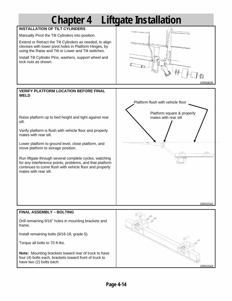
GR01542 FINAL ASSEMBLY – BOLTING Drill remaining 9/16” holes in mounting brackets and frame. Install remaining bolts (9/16-18, grade 5). Torque all bolts to 70 ft-lbs. Note: Mounting brackets toward rear of truck to have four (4) bolts each, brackets toward front of truck to have two (2) bolts each. GR01543
Platform flush with vehicle floor
Platform square & properly mates with rear sill

Chapter 4 Liftgate Installation
Page 4-15
FINAL ASSEMBLY - WELDING Alternatively to bolting, mounting brackets can be welded. Welding area must be cleaned with grinder to remove all paint. Weld all four (4) brackets to frame as shown.
GR01539 INSTALL UP STOPS AT BED HEIGHT
Liftarm movement up must be limited mechanically. Rear sill is not strong enough to withstand forces from liftgate.
Use 2” x 2” x .25 tube (or similar) to limit up movement of lift arm as shown.
Material for up stops is not provided.
Raise platform to bed height.
Position up stops on top of lift arms and against vehicle chassis frame.
Tack weld up stops to chassis frame and lower platform to the ground.
IMPORTANT! Verify that hydraulic hoses or wires will not get crushed between lift arms and up-stops.
GR01169
Make sure that up stops will contact lift arms as shown on drawing.
IMPORTANT! Up stop must contact lift arms as shown.
GR00455
Bed Height
Up-Stops

Chapter 4 Liftgate Installation
Page 4-16
Add support beam or gusset to up stop to prevent up stops bending.
Material for this is not provided.
IMPORTANT! Add support to up stops to prevent bending.
GR01170 INSTALL UP STOPS IN STORAGE POSITION
Move platform to storage (transport) position.
Lower platform to be same level with frame as shown.
Locate up-stops inside the tracks, so they secure deck extension. Location approximately as shown.
It may be necessary to use provided plate to get up-stops close enough to extension surface.
1/41/4
1/4
1/4
GR01533 GR01536
Locate UP-Stops to Contact Deck Extension
Gusset
Provided Plate

Chapter 4 Liftgate Installation
Page 4-17
PLATFORM FOLDING GUIDE With 78” deep or deeper platforms, you may need to install folding guides. If you find during liftgate movement (with platform folding) into storage position, that the platform interferes with either locking valve on top of tilt cylinders, install Platform Folding Guide Kit (80001101) to prevent platform from damaging lock valves. Locate rectangular aluminum tubing (from kit 80001101) on lift arms with 2” dimension as shown and 1” Dia. holes up. Secure in place with C-clamps. Verify position of tubing by moving liftgate and platform through required motions. Upon tubing position verification, drill .358” diameter holes into lift arm, aligned with holes in tubing. Install 3/8-16 self-tapping screws. Remove C-clamps. Verify all motions and storage of liftgate/platform to operate properly with no interference problems.
2"
GR01526 GR01527 GR01528
Platform hitting lock valve
Aluminum (tubing) guides installed
1” Dia. holes

Chapter 4 Liftgate Installation
Page 4-18
CONSTRUCTION OF TILT CYLINDER
1. Adapter
2. Adjustable case
3. Lock nut
4. Lock screw
GR00502 ADJUSTING TILT DOWN ANGLE
Remove locking screw.
Screw adapter out.
GR00506
Tilt platform down to desired tilt down angle.
Recommended tilt down angle is 10°.
GR00577
Screw adapter against top of the cylinder in both cylinders.
Tighten lockscrew in adapter in both cylinders.
Test all the functions of liftgate.
GR00506
10°
ADJUSTABLE CASE
LOCK SCREW
ADAPTER
LOCK NUT
LOCK SCREW
SCREW ADAPTER OPEN
LOCK SCREW
SCREW ADAPTER IN

Chapter 4 Liftgate Installation
Page 4-19
INSTALLATION OF MARKER LIGHTS
Route marker light wire from platform to control unit.
Plug caution light connector to similar connector that comes out from control unit.
NOTE: Secure marker light wire to lift arms and frame with wire ties. Make sure that cable doesn’t pinch when gate moves up and down.
GR00509 SWING DOOR APPLICATION
Platform must be spaced away from the vehicle’s door lock parts when the liftgate is in the operating position.
Make sure that there is enough clearance between platform and rear sill when platform is tilted up or down.
1/4" REFERENCE
DOOR LOCKS GR00906
It maybe necessary to build ramp between vehicle and platform to fill cap between rear sill and platform.
Build and install ramp approximately as shown.
GR01042
Controls must be mounted so they can be used when doors are open.
If necessary add a plate so that decals can be mounted below door as shown.
18"
GR01538
CONNECTOR
MARKER LIGHT WIRE
Decals
Controls

Chapter 5 Placement of Decals
Page 5-1
INSTALLATION OF CONTROL DECALS Install all decals listed below. Be certain they are installed in the proper location and are legible.
NOTE! All decals must be in place and legible or all warranties are void!
Each of the following four (4) decals are to be positioned in a conspicuous place near the control switches as shown.
80100850 – Safety Instruction Decal
80101437 – Operation Decal
80100828 – Important Decal
80101370 – Hazard decal
One (1) of the following two (2) decals is to be positioned in a conspicuous place near the control switches as shown.
80101416 – BZ-44 Capacity Decal
80101417 – BZ-55 Capacity Decal
Note: A second set of the previous five (5) decals must be installed if unit is equipped with dual controls
GR01540 KEEP CLEAR DECALS Locate to vehicles rear sill as shown.
75089296 – Stand Clear Decal (2)
GR01541
PLACE DECALS IN THIS AREA
Chapter 5 Placement of Decals
Page 5-2
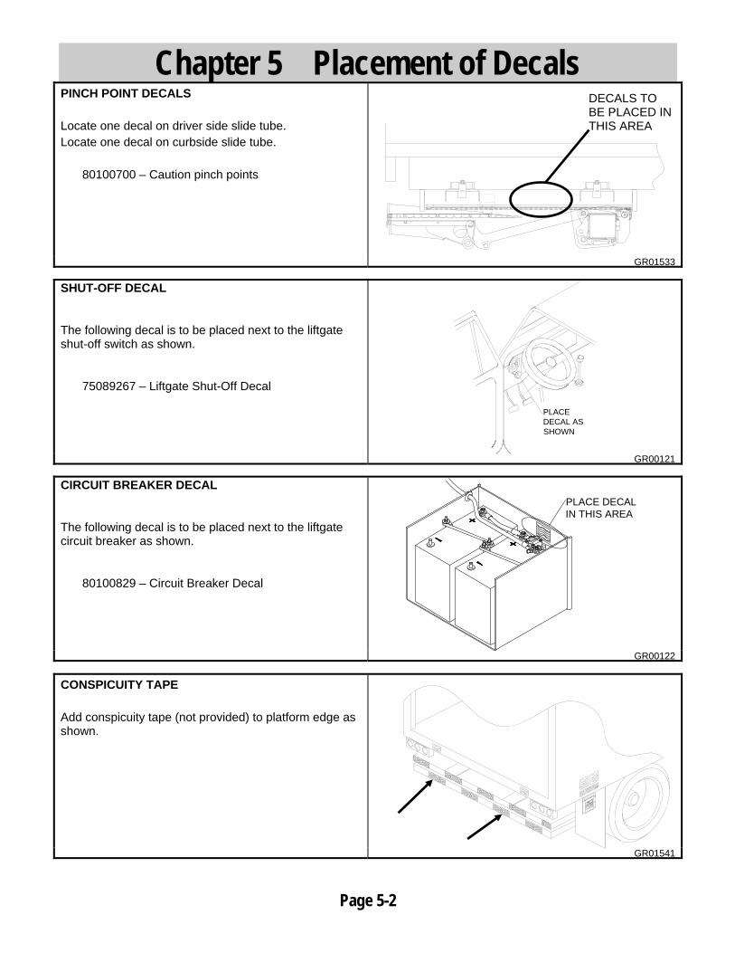
PINCH POINT DECALS Locate one decal on driver side slide tube. Locate one decal on curbside slide tube.
80100700 – Caution pinch points
GR01533 SHUT-OFF DECAL
The following decal is to be placed next to the liftgate shut-off switch as shown.
75089267 – Liftgate Shut-Off Decal
PLACE DECAL AS SHOWN
GR00121 CIRCUIT BREAKER DECAL
The following decal is to be placed next to the liftgate circuit breaker as shown.
80100829 – Circuit Breaker Decal
PLACE DECALIN THIS AREA
GR00122
CONSPICUITY TAPE Add conspicuity tape (not provided) to platform edge as shown.
GR01541
DECALS TO BE PLACED IN THIS AREA

Chapter 6 Lubrication
Page 6-1
LUBRICATION INSTRUCTIONS
12 grease fittings should be lubricated with a grease gun per the lubrication schedule below.
Note: All fittings should be greased with the platform in the stored position. Note: If unsure of duty or cycles always lubricate more frequently.
1. Tilt cylinder, lower pin 2. Lift cylinder, lower pin 3. Lift arm, lower pin 4. Tilt cylinder, upper pin 5. Lift cylinder, upper pin 6. Lift arm, upper pin 7. Wheels inside slide profile, 4 plcs
GR01352
SUGGESTED MINIMUM LUBRICATION SCHEDULE (IN DAYS)
Monthly Cycles Light Duty Med. Duty Heavy Duty
250 Or Less 45 30 21
250-350 30 21 14 350-450 21 14 7
More Than 450 Contact Factory for Instructions
1
2
3
4
5
6
7
Page 7-1
Chapter 7 Final Inspection List
IMPORTANT All of the following items are to be checked and verified before installation is complete.
A. All welds are properly done.
B. All bolts, nuts, and screws are tight and torqued to the proper specification.
C. Control boxes and shut off switch function properly.
D. All phases of the liftgate’s operation work properly.
E. Platform raises level to the truck bed and the gap between the platform and sill extension is the correct distance.
F. All decals are installed for and legible.
G. Lights are installed and operate properly.
H. Vehicle meets all state and federal standards.
I. Owner’s Manual is in the vehicle.
J. Pump reservoir is full of oil.
K. All grease fittings are lubricated.
L. All hydraulic connections are tight.
M. Up stops, Drive-Over Bars and Platform Bridge are installed and operate properly. (if applicable)
N. Pump and Motor Slide tray is tightly latched.
O. Liftgate has been operated through its entire operational cycle several times and operates evenly, freely and smoothly throughout the entire operating cycle with no unusual noise or vibration.
Do not use liftgate if any of the above are not checked and verified.
If you have any questions not covered in this manual, please contact your nearest Waltco distributors, or the nearest Waltco factory.

80101389 Page 8-1 EO 5534A Rev 02
Chapter 8 – How To Order Parts Repairs should be made only by authorized mechanics using WALTCO Replacement parts. When ordering repair or replacement parts, please include all the information asked for below. If this information is not available, a complete written description or sketch of the required part will help WALTCO identify and deliver the needed part to you. ________________________________________________________________
THE FOLLOWING INFORMATION MUST BE INCLUDED:
1. SERIAL NUMBER - [WALTCO liftgate serial numbers can be found on the Specification Tag attached to the mount frame. (On older units the Specification Tag is located on the side or bottom of the platform.)]
2. MODEL NUMBER - [Or capacity] 3. PLATFORM SIZE ________________________________________________________________
THEN INCLUDE THE FOLLOWING INFORMATION:
4. PART NUMBERS 5. DESCRIPTION 6. QUANTITY REQUIRED ________________________________________________________________
MAIL, E-MAIL OR PHONE YOUR REQUEST TO:
Waltco Truck Equipment Co. 285 Northeast Avenue Tallmadge, OH 44278
1-800-411-5685 FAX: 1-800-411-5684
E-MAIL: [email protected] ALL PARTS ARE F.O.B. FROM THE SHIPPING FACTORY ________________________________________________________________
PLEASE NOTE:
To assure you of continuing and effective quality control, our warranty policy permits replacement of hydraulic cylinders, valves and motor pump units when their factory seals are intact. Parts under warranty will be exchanged promptly after careful inspection of the returned assemblies. ________________________________________________

IMPORTANT
TO BE KEPT IN VEHICLE __________________________________________________________
CAUTION:
STAND CLEAR AND KEEP CLEAR OF PLATFORM AREA WHILE OPERATING LIFTGATE.
__________________________________________________________
FOR OPERATION OF THIS UNIT, REFER TO THE “OPERATION INSTRUCTIONS” INSIDE THE OWNER’S MANUAL AND THE OPERATION INSTRUCTIONS DECAL.
LUBRICATION INSTRUCTIONS
Refer to the lubrication chart in this manual.
DO’S AND DON’TS
DO: Make certain area in which the platform will open and close is clear before opening or closing platform. DO: Make certain platform is properly latched when in transit. DO: Make certain platform area, including the area in which loads may fall from platform, is clear before and at all times during operation of the liftgate. DO: Operate the liftgate with the control switches only. DO: Check oil level monthly and change oil yearly. DO: Use hydraulic fluids listed on the HYDRAULIC FLUID CHART (found inside this manual) or equivalent. DO: Lubricate as per the LUBRICATION INSTRUCTIONS AND LUBRICATION SCHEDULE found in this book. DO: Read and follow WARNING DECALS, OPERATION DECALS and OWNER’S MANUAL. DO: Visually inspect the liftgate frequently and keep it in adjustment. DO: Be certain vehicle is properly and securely braked before using the liftgate. DO: Repair the liftgate when it is found to be faulty to prevent accidents. DO: Keep all decals in place and legible and retain the Owner’s Manual in the vehicle or ALL WARRANTIES ARE VOID. DON’T: Allow the liftgate to be used by persons not familiar with its operation. DON’T: Use the liftgate if unit shows signs of abuse or fails to operate freely. DON’T: Permit the motor to run after the liftgate is raised to bed level. DON’T: Overload the liftgate (Refer to Manual for proper capacity of liftgate). DON’T: Use brake fluid.
80101390 Rev 01