0 Front Cover - teijin-seiki.comteijin-seiki.com/AR Manual.pdf · The copyright for this entire...
175
TMF00007E 01/Oct.'03 Before attempting to operate this product, you should thoroughly read and fully understand all the contents of this manual. Specifications are subject to change without notice. Vigo Servo AR Series Instruction Manual Carefully note the precautions on pages 1-4,5,6,7 before turning on the power supply. Software version (See page7-5 for details) : From 01.10 Servo amplifier : ARN15-A/30-A/60-A/135-A Servo actuator : AR15/30/60/135/H7/H17/H24/10H - Applied models -
Transcript of 0 Front Cover - teijin-seiki.comteijin-seiki.com/AR Manual.pdf · The copyright for this entire...

TMF00007E 01/Oct.'03
Before attempting to operate this product, you should thoroughlyread and fully understand all the contents of this manual.
Specifications are subject to change without notice.
Vigo Servo AR Series
Instruction Manual
Carefully note the precautions on pages 1-4,5,6,7before turning on the power supply.
Software version (See page7-5 for details) : From 01.10
Servo amplifier : ARN15-A/30-A/60-A/135-A
Servo actuator : AR15/30/60/135/H7/H17/H24/10H
- Applied models -

For your safety
• To prevent accidents, strictly follow the procedures and cautions noted in this manual.Safety information for the prevention of danger is given in "1. ON SAFETY" in this manual.
• A warning label marked (electrical shock) is affixed to the servo amplifier front panel.
•
•
•
•
Very serious accidents may occur if this instruction is not observed.
Do not turn on the machine's power supply until all the noted precautions have been studied and understood.
This manual provides general guidelines, precautions and warnings for the safe operation of this machine.
Please be sure to deliver this instruction manual to all administrators and operators charged with the operation of this machine.They must carefully read this manual and fully understand its contents, and should not let anyone who is not familiar with the contents of this manual operate or inspect this machine.Keep this manual available near the equipment at all times so that it can be immediately referred to whenever necessary.
Look up the name, address and phone number of our nearest dealer or branch office listed on the back page of this manual, and post the information prominently for quick reference.
All machine operators must read "1. ON SAFETY" in this manual carefully and thoroughly.
WARNING
From Chapter 2, safety information is given for any task or operation that is potentially dangerous and each of these messages is prefaced with the appropriate signal word.
Be careful to avoid injury from shock, as electrical circuits are incorporated in the area near this label. (See pages 5-1,3)
If this machine is used in ways other than those described in this manual, unforeseen problems or accidents may occur, and we shall bear no liability or responsibility for the consequences.
This manual contains important information you must know about the AR series servo system, which consists of a servo actuator and a servo amplifier, its safety features, and necessary operating precautions. Be sure to read it thoroughly before attempting to transport, install, wire, operate, service or inspect the servo system.
?
Page
To comply UL and/or CUL standardPreface
Servo Amplifier
SpecificationsCommunication ContentsTransmission FormatDetailed Description of Transmission Contents
Initialization
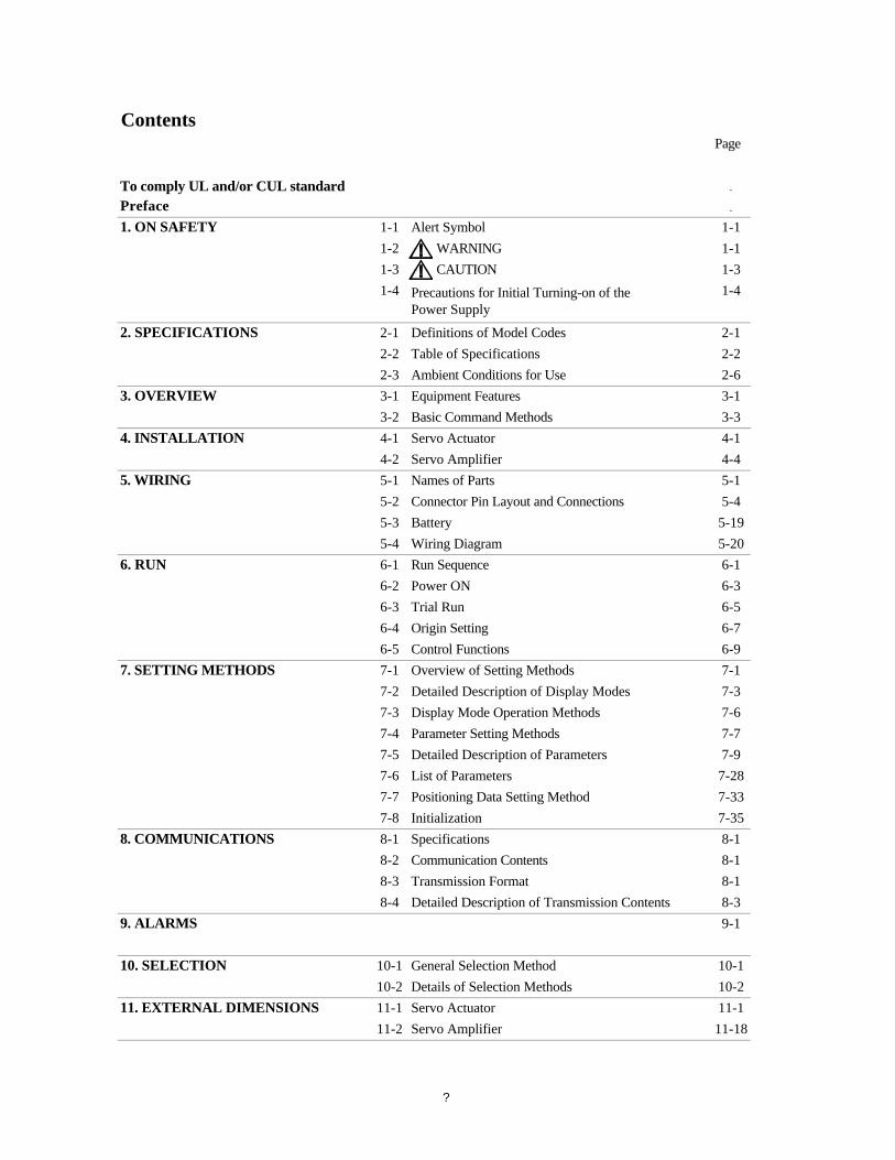
Contents
Details of Selection MethodsServo Actuator
Parameter Setting MethodsDetailed Description of ParametersList of ParametersPositioning Data Setting Method
Control FunctionsOverview of Setting MethodsDetailed Description of Display ModesDisplay Mode Operation Methods
Run SequencePower ONTrial RunOrigin Setting
Connector Pin Layout and ConnectionsBatteryWiring Diagram
Servo ActuatorServo Amplifier
5-195-20
4-14-4
Alert SymbolWARNING
11-18
1. ON SAFETY
Precautions for Initial Turning-on of the Power Supply
Definitions of Model CodesTable of SpecificationsAmbient Conditions for UseEquipment FeaturesBasic Command Methods
CAUTION1-4
7-77-9
7-287-33
10-211-1
7-358-18-18-1
9-18-3
10-1
7-37-6
6-16-36-56-76-97-1
5-15-4
11-2
1-11-11-3
2-12-22-6
Names of Parts
3-13-3
8-4
10-1
7-67-77-88-1
6-36-4
10-211-1
General Selection Method
9. ALARMS
8-28-3
7-27-37-47-5
6-57-1
5-35-46-16-2
4-14-25-15-2
1-11-21-3
2-1
1-4
2-22-33-13-2
2. SPECIFICATIONS
3. OVERVIEW
11. EXTERNAL DIMENSIONS
6. RUN
5. WIRING
4. INSTALLATION
10. SELECTION
8. COMMUNICATIONS
7. SETTING METHODS
?

To comply UL and/or CUL standard,please keep in mind the following points.
This equipment is to be installed in an enclosure that provides a pollution degree 2 (controlled) environment (Normally, only nonconductive pollution.However, temporary conductivity caused by condensation may be expected.
These devices are suitable for factory wiring using Nos.2 1 AWG copper wire.Use 60 75 wire or the equivalent for ARN15 and ARN30.Use 75 wire or the equivalent for ARN60 and ARN135.Tighten field wiring terminal (TB1 TB3) to 4.4 lb-in for ARN15 and ARN30.Tighten field wiring terminal (TB1) to 11.0 lb-in for ARN60 and ARN135.Tighten field wiring terminal (TB3) to 4.4 lb-in for ARN60 and ARN135.
Suitable for use on a circuit capable of delivering not more than 5000 rms symmetrical amperes, 240 volts maximum, when protected by circuit breaker having an interrupting rating not less than 15 rms symmetrical amperes, 240 volts maximum.
Suitable for use on a circuit capable of delivering not more than 5000 rms symmetrical amperes, 240 volts maximum, when protected by circuit breaker having an interrupting rating not less than 20 rms symmetrical amperes, 240 volts maximum.
Suitable for use on a circuit capable of delivering not more than 5000 rms symmetrical amperes, 240 volts maximum, when protected by circuit breaker having an interrupting rating not less than 30 rms symmetrical amperes, 240 volts maximum.
CAUTION
?

- Preface -
Preface
1. Purpose
This program should be designated by the industrial equipment engineer.The end user can operate the servo system by executing the program.
Operation of the servo actuator is controlled by the parameters set for the servo amplifier.
Therefore, please keep in mind the following points.
(1)
(2)
(3)
(4)
(5) You must not modify the servo amplifier or the servo actuator.
2. Intended readers
This manual is intended for use by engineers in the development of industrial equipment.
3. Requests to industrial equipment manufacturers
If this servo system is to be used for any purpose or in any environment mentioned in (1) to (4) above, please consult with us before proceeding any further.
We therefore hereby authorize each manufacturer to copy, reprint, or reproduce the contents of this manual for these purposes only.
It describes information and procedures for choosing suitable specifications for the incorporation of the servo system into the industrial equipment, its installation, settings and equipment operation.
To prevent injuries or harm to any person using machines, which incorporate our servo system (hereafter referred to as "end user"), each industrial equipment manufacturer should reprint the instructions and precautions noted in "1. ON SAFETY" in their own machine instruction manuals for the end user.
The servo system cannot be used with any devices that affect people's bodies or health, such as medical appliances.The servo system must not be used with any devices that could adversely affect the environment or public safety, such as railway vehicles, aircraft, toys and passenger elevators.The servo system cannot be used in environments, which are subject to strong vibrations, such as in automotive vehicles, marine vessels, etc.The servo system cannot be used in certain special environments, i.e., nuclear environments with ambient radiation, high vacuum space environments, etc.
Teijin Seiki's "AR servo actuator and ARN servo amplifier" (hereafter simply termed "servo system") has been developed for use with servo systems for general industrial equipment.
When the power supply to the industrial equipment is turned on, the servo system operates in accordance with the program set in the machine sequencer.
The servo amplifier is activated by the signals input to and output from the industrial equipment sequencer.
For example, the servo system is used for driving a machine tool ATC magazine, transfer unit arm, index table, conveyor, press or other device into position.
?

- Preface -
4. Exporting the servo system
5. Product warranty
6. Usage liability
7. Copyright
© 2000: TS The copyright for this entire manual belongs to Teijin Seiki Co., Ltd. Copying, reprinting or reproduction of this manual in whole or in part in any media without our express consent infringes upon the copyright and the rights of the publisher.
The data noted in this manual is only offered as sample reference data for normal usage of this machine.
We shall bear absolutely no liability or responsibility for the consequences if this machine is utilized for purposes other than those described in this manual.
We assume no responsibility or liability for any damage or consequential and/or indirect losses resulting from any accident or malfunction that might occur during the operation of this machine.
We shall not be held responsible for any damage caused by conditions beyond our control such as customer modifications, disassembly or misuse of our products, or their use in a defective or deficient environment.
We shall not bear any legal responsibility for its suitability for each customer's particular uses nor shall we be held liable for any incidental or indirect damages caused by usage of the machine itself.
However, we will not bear incidental costs, such as man-hours required to remove from and/or install to the equipment, transportation costs, taxes, warehouse charges, etc.We shall also not compensate losses resulting from the stoppage of any equipment that incorporates the servo system due to problems caused by the servo system.If we make financial compensation for the product, the maximum amount of the compensation shall not exceed the sales price of the applicable product.
Please note that machine specifications are subject to change without notice for updates and improvements. This may cause inconsistencies between the contents of this manual and the machine you currently possess.
When incorporating the servo system into its machines, each industrial equipment manufacturer must carefully observe all the procedures and cautionary notes included in this manual to prevent injuries or accidents caused by its improper installation or operation.
International transfer of this machine, any of its parts, components and/or software must be carried out in compliance with the relevant laws and ordinances of the country of export and the country of equipment end-use.We do not assume any responsibility or liability for equipment transferred without regard to proper export/import regulations or procedures.
The term of warranty on the servo system is either one year from installation or 2000 running hours after incorporation into the equipment, whichever is shorter, under condition that proper setup and wiring have been carried out in accordance with the ratings we stipulate.
?

- On Safety -
1-1 Alert Symbol
Please understand the meanings of both symbols and strictly follow their instructions.
WARNING
CAUTION
Please consult us before using this machine in specialized environments.
1-2 WARNING
Only skilled technicians should perform these tasks.Attempts by nonqualified personnel could lead to electrical shock, injury, or fire.
Ignoring this instruction could lead to electrical shock. (See page 5-11.)
Stay away from the rotating section of the servo actuator while the power is supplied.Ignoring this instruction could lead to serious injury.
The PE terminals of both servo actuator and servo amplifier must be grounded to prevent electrical shock.
Do not expose the machine to gases that may cause the machine to corrode or an explosion to occur.
Indicates a potentially hazardous situation that, if not avoided, could result in minor or moderate personal injury or damage to the machine.
This machine has not been designed or manufactured for use with any device or system that may affect people's lives.
For use with facilities, which may affect people's lives or may cause serious damage to the machine resulting from machine fault, be sure to install safety devices appropriate to the facilities.
To prevent electrical shock, be sure to turn off the power supply before beginning installation, removal or wiring of the machine.
Make the ground cable 2 to 3 cm longer than L1, L2, and L3 and U,V, and W so that it will be the last to disconnect if either the main power cable or servo actuator power line is forcibly disconnected.
1. ON SAFETY
This chapter contains precautions on using this machine, which must be observed to ensure operator safety.
This manual marks important safety information with two alert symbols, "WARNING" and "CAUTION", corresponding to the level of potential danger involved.
Indicates a potentially hazardous situation that, if not avoided, could result in death or serious injury.
1-1

- On Safety -
Use the hanger bolt with the nominal diameter specified in "11. EXTERNAL DIMENSIONS".Use of another size bolt could lead to serious injury.
If this instruction is ignored, the servo actuator can drop and may cause serious personal injury.
Ignoring these instructions could lead to serious injury.
Therefore, never touch the rotating section unless it is completely stopped.Ignoring this instruction could lead to serious injury.
Do not start wiring until the Charge LED on the front panel of the servo amplifier goes out.Ignoring this instruction could lead to electrical shock.
Do not heat the battery to 100 °C or above (Do not incinerate the battery).Ignoring this instruction could lead to ignition, combustion and explosion.
Do not re-charge the battery. Ignoring this instruction could lead to explosion or leakage.Contact of the eyes with battery contents could lead to loss of eyesight.
Hang the servo actuator with a hanger bolt when installing, removing or transferring the servo actuator so that it will not drop.
The type of machine to which the servo actuator is installed, its setup environment, and the mass and torque of the servo actuator must be carefully considered when designating the dimensions and materials for the section to which the servo actuator is installed and the installation method.
Observe the following preventive measures to avoid hazards that could result from servo system rotation.
The servo actuator can keep rotating due to load or inertia even when the power supply is turned off.
Although the power supply is turned off, the servo amplifier will have been charging with high voltage for a while.
A battery is used for the absolute encoder type servo system. Keep in mind the following precautions when handling the battery.
Do not disassemble the battery. Contact of the eyes with battery contents could lead to loss of eyesight.
In case of an emergency stop, turn off the main power supplies (L1, L2 and L3) to the servo amplifier to stop the servo actuator safely. Ignoring this instruction could lead to serious injury from unexpected servo actuator rotation.
1-2

- On Safety -
1-3 CAUTION
Do not perform an high voltage insulation resistance test of the servo system.Ignoring this instruction could lead to damage to the servo system or electrical shock.
Do not jar the servo actuator.Ignoring this instruction could damage the encoder inside of the servo actuator.
Keep excess water and oil away from the servo actuator. Also, do not allow water and oil to enter the connectors along the cables. Ignoring these instructions could lead to damage to the servo system or electrical shock.
Securely tighten all the fixing bolts for the servo system. If any bolts are loose, the servo system may shift or drop, and damage to the other parts of the equipment or personal injury could result.
Use the servo actuator and the servo amplifier in accordance with the combinations stated in the "Table of Specifications" on pages 2-2,3,4,5. If they are used with any other combinations, fire, burns or electrical shock could occur.
Do not connect the commercial power supply to the output terminals (U, V and W) of the servo amplifier or to the input terminals (U, V and W) of the servo actuator. Ignoring this instruction could lead to electrical shock, burns or fire.
If an error has occurred in the servo system, do not operate it until the appropriate remedy has been applied. Ignoring this instruction could lead to serious injury or electrical shock.
The servo system may reach high temperatures during operation. To prevent burns, do not touch the servo system immediately after the power supply is turned off, but wait for the system to cool.
1-3

- On Safety -
1-4 Precautions for Initial Turning-on of the Power Supply
Make sure that the encoder selector switch has been set to ABS(absolute) as noted on pages 5-2,3.If not , Following the instruction on these page, alter the setting to ABS.
Do not connect the battery (p5-19) for the absolute encoder.
Turn on the main and control power supplies. (See pages 5-10,13)When the power is turned on, the front panel of the main unit shows"HELLO Arn** AbS".Alarm(p9-1) appears on the front panel after "HELLO Arn** AbS".
Wait approximately five minutes in this state, to charge the capacitor inside of the encoder.
Turn off the main and control power supplies.Turn on the main and control power supplies again.
Supply the power to the brake. (See page 5-14)
When a servo actuator incorporating a brake function (p2-1) is used , if the power for brake has not been supplied, a brake power supply disconnection alarm (AL-10) will occur (p9-3) as soon as an "Operation ready command (p6-9)" is issued.
If it is first connected, excessive current could be supplied from the battery to the capacitor in the encoder, which may cause the battery to deteriorate.
Since the information concerning the absolute encoder has been lost, "AL-13" (Encoder system down, page 9-3) is displayed.
When the main power and the control power are first turned on, follow the procedures below. Before beginning each procedure, carry out wiring according to the instructions in "5. WIRING" on page 5-1.
If these pins are not shorted, an overvoltage alarm (AL-4, page 9-2) may occur during regenerative operation.
For absolute encoder type specifications
In all cases, except when using external regenerative resistance, short the RGEN and DCC pins on connector TB2(ARN15,30) or TB1(ARN60,135) for motor power cable/external regenerative resistance, using a conductor whose cross-sectional area is not less than 1.25 mm², according to the description on pages 5-12,13.
Select and define the alarms to be used. In order to avoid any signals that might disturb the smooth start-up of the machine, leave the CN2 connector (for control I/O signals, page5-1,5-3) disconnected.
Follow the "5.WIRING" and connect the servo amplifier and servo actuator to the peripheral devices.
1-4

- On Safety -
Perform an origin setting from the panel switches following the instructions on page 6-7.
Turn off the main and control power supplies.
Connect the battery to the battery connector. (See page 5-19)
Turn on the main and control power supplies again. The machine can now operate.
(Since the servo actuator cannot operate in this state, the output shaft position cannot be set to the mechanical origin. Therefore, designate the current output shaft position as the origin.)
When a servo actuator without a brake function is used, change the setting of control parameter 7 to “2” (unavailable) according to the description on page 7-7.
When a servo actuator without a brake function is used, since control parameter 7 (CP-7) (p7-15) has been set to 1 (available) by default for brake available/unavailable selection, a brake power supply disconnection alarm (AL-10) will occur when an “Operation ready command” is issued.
1-5

- On Safety -
Battery (p5-19) connection is not required.
The encoder selector switch has been set to ABS (absolute) as noted on pages 5-2,3.Following the instruction on these pages, alter the setting to INC (incremental).
When the power is turned on, the front panel of the main unit shows"InIt.I HELLO Arn** InC"
Supply the power to the brake. (See page 5-14)
Turn off the main and control power supplies.
Turn on the main and control power supplies again. The machine can now operate.
If these pins are not shorted, an overvoltage alarm (AL-4, page 9-2) may occur during regenerative operation.
When a servo actuator without a brake function is used, change the setting of control parameter 7 to “2” (unavailable) according to the description on page 7-7.
Failure to do so results in the display of “AL-11”(Encoder Trouble) or “AL-14”(Encoder type mismatch)(See page 9-3).
Holding down the UP ? and DOWN ? buttons at the front of the servo amplifier, turn on the main and control power supplies (p5-10,13). (See page 7-35)The setting of control parameter 1 (CP-1) for choosing the encoder type (p7-13) will be changed from "1" (absolute AR) to "2" (incremental AR).
When a servo actuator incorporating a brake function (p2-1) is used , if the power for brake has not been supplied, a brake power supply disconnection alarm (AL-10) will occur (p9-3) as soon as an "Operation ready command (p6-9)" is issued.
When a servo actuator without a brake function is used, since control parameter 7 (CP-7) (p7-15) has been set to 1 (available) by default for brake available/unavailable selection, a brake power supply disconnection alarm (AL-10) will occur when an “Operation ready command” is issued.
Follow the "5.WIRING" and connect the servo amplifier and servo actuator to the peripheral devices.
Select and define the alarms to be used. In order to avoid any signals that might disturb the smooth start-up of the machine, leave the CN2 connector (for control I/O signals, page5-1,5-3) disconnected.
For incremental encoder type specifications (other than AR10H)
In all cases, except when using external regenerative resistance, short the RGEN and DCC pins on connector TB2(ARN15,30) or TB1(ARN60,135) for motor power cable/external regenerative resistance, using a conductor whose cross-sectional area is not less than 1.25 mm², according to the description on pages 5-12,13.
1-6

- On Safety -
• Battery connection is not required.
•
• The encoder selector switch has been set to ABS (absolute) as noted on pages 5-2.Following the instruction on that page, alter the setting to INC (incremental).
•
And internal motor contorol parameters will be changed for AR10H.If do not execute this, ARN30 can not be used for AR10H.When the power is turned on, the front panel of the main unit shows"InIt.H HELLO Arn30 10H"
•
Supply the power to the brake. (See page 5-14)
•
• Turn off the main and control power supplies.
• Turn on the main and control power supplies again. The machine can now operate.
For AR10H (incremental encoder type specifications)
Follow the "5.WIRING" and connect the servo amplifier and servo actuator to the peripheral devices.
Select and define the alarms to be used. In order to avoid any signals that might disturb the smooth start-up of the machine, leave the CN2 connector (for control I/O signals, page5-1,5-3) disconnected.
When a servo actuator without a brake function is used, change the setting of control parameter 7 to “2” (unavailable) according to the description on page 7-7.
Make sure that model code of servo amplifier is ARN30
If these pins are not shorted, an overvoltage alarm (AL-4, page 9-2) may occur during regenerative operation.
Failure to do so results in the display of “AL-11”(Encoder Trouble) or “AL-14”(Encoder type mismatch)(See page 9-3).
Holding down the MODE and UP ? buttons at the front of the servo amplifier, turn on the main and control power supplies (p5-10). (See page 7-35)The setting of control parameter 1 (CP-1) for choosing the encoder type (p7-13) will be changed from "1"(absolute AR) to "3" (incremental AR10H).
When a servo actuator without a brake function is used, since control parameter 7 (CP-7) (p7-15) has been set to 1 (available) by default for brake available/unavailable selection, a brake power supply disconnection alarm (AL-10) will occur when an “Operation ready command” is issued.
When a servo actuator incorporating a brake function (p2-1) is used , if the power for brake has not been supplied, a brake power supply disconnection alarm (AL-10) will occur (p9-3) as soon as an "Operation ready command (p6-9)" is issued.
In all cases, except when using external regenerative resistance, short the RGEN and DCC pins on connector TB2 for motor power cable/external regenerative resistance, using a conductor whose cross-sectional area is not less than 1.25 mm², according to the description on pages 5-12.
1-7

- Difinitions of Model Codes -
2-1 Definitions of Model Codes
(1) Servo actuator
Reduction gear ratio
Type indication (A,B,C,F,S,H)
Availability of brake Type of encoder Option
Regulation numbers of UL and EN to which AR series are supported are shown below.
Type indication of each actuator model
(2) Servo amplifier
Option
(3) Battery (p5-18) 21EP002
European safety standards
Standard specification
0
Available
T
I
UL, EN standards supportedUnavailable
A
B
Required when an absolute encoder is used. (-AB : battery is attached)
Series name (AR/ARH) Frame No.
EN50178
UL standardsCSA C22.2 No.14
0
CSA C22.2 No.100-95
2. SPECIFICATIONS
AR 135 A B
Incremental (INC)
-128 0
TB3 (p5-14) connector and battery (p5-
18) attached
Unavailable
ARN 135
Series nameFrame No.
- A B
ARN60,135ARN15,30
Absolute (ABS)
Servo actuator UL1004
CUL standards
A
Servo amplifier UL508C
B
---- Unavailable
TB1 (p5-10),TB2 (p5-12),TB3 (p5-14)
connector and battery (p5-18) attached
2-1

- Table of Specifications -
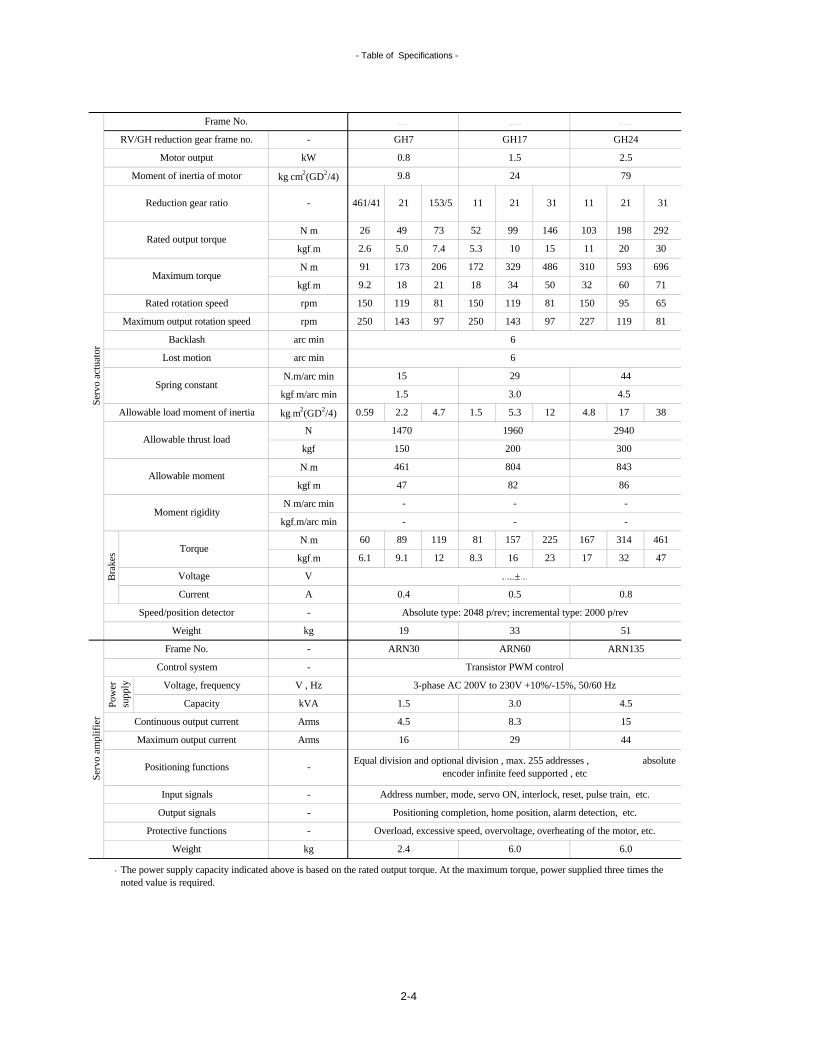
2-2 Table of Specifications
The power supply capacity indicated above is based on the rated output torque. At the maximum torque, power supplied three times the noted value is required.
kg
Output signals
Protective functions
2.4
Overload, excessive speed, overvoltage, overheating of the motor, etc.
2.4
Positioning completion, home position, alarm detection, etc.
Serv
o am
plif
ier
-
-
-
Maximum output current
Frame No.
Control system
Voltage, frequency
kVA
Arms
Serv
o ac
tuat
orB
rake
s
Weight
Equal division and optional division , max. 255 addresses , absolute encoder infinite feed supported , etc
Weight
Positioning functions
Input signals
CapacityPow
ersu
pply
Continuous output current
Torque
Voltage
Current
Speed/position detector
Spring constant
Allowable thrust load
Allowable moment
Moment rigidity
Rated rotation speed
Maximum output rotation speed
Backlash
Lost motion
Frame No.
Reduction gear ratio; types C
Rated output torque
Maximum torque
RV/GH reduction gear frame no.
Motor output
Reduction gear ratio; types A, B
Moment of inertia of motor kg cm2(GD2/4)
kgf m
RV40E-
170
N
kgf
N m
kgf m
1960
62
0.3
12 15
RV15A2
12.5 27
274
0.4
22 29 36
±
8.8 19
24
212 282
5194
530
1666
162
28 2828
17
608
24
27 28
34
54
Absolute type: 2048 p/rev; incremental type: 2000 p/rev
1.5
9
461
47
263 274 274 274274 659 856 1029
200
67
3121
25
45 31
56
3.5
86 115 143 186
80 104 140
57
56 80 104 152120
81 105 15381 105 141 57 121
36366 94 122 167 282
13 19 25
132 188 245
6.7 9.6 12 17
4518
29
24
87 105
25
29
16
37
988
101
kg m2(GD2/4)
N m
kgf m
V
N m/arc min
A
-
-
V , Hz
Arms
-
0.4
kgf m/arc min 28
120
121
141
14
-
0.8
5.2 11 18 32 11331
108
53
3.3
15 30
kg
N m
N m/arc min
kW
-
-
N m
15
9.8
Allowable load moment of inertia
kgf m
rpm
kgf m/arc min
rpm
arc min
arc min
11
21
1
2054 3838 29 21
1
71
931
400
50
95
494
41
353
16
Address number, mode, servo ON, interlock, reset, pulse train, etc.
ARN15 ARN30
Transistor PWM control
3-phase AC 200V to 230V +10%/-15%, 50/60 Hz
4.5
1.0
2.7
2-2

- Table of Specifications -
The power supply capacity indicated above is based on the rated output torque. At the maximum torque, power supplied three times the noted value is required.
Serv
o ac
tuat
orB
rake
s
Equal division and optional division , max. 255 addresses , absolute encoder infinite feed supported , etcSe
rvo
ampl
ifie
r
-
-
-
6.0
107
0.8
73.5
ARN135
Transistor PWM control
131 165 184 215
392
40
253
14700
395
135
RV160E
2.5
79
2258
230
25
31
80
81
753
77
Weight
Weight
Positioning functions
Input signals
Output signals
Protective functions
CapacityPow
ersu
pply
Continuous output current
Maximum output current
Control system
Voltage, frequency
Allowable thrust load
Moment rigidity
Frame No.
Current
Speed/position detector
Allowable load moment of inertia
Allowable moment
Torque
Voltage
Maximum output rotation speed
Backlash
Lost motion
Spring constant
kg
RV/GH reduction gear frame no.
Motor output
Reduction gear ratio; types A, B
Reduction gear ratio; types C
Rated output torque
Maximum torque
Rated rotation speed
Arms
Arms
-
-
-
V , Hz
kVA
-
kg
kgf m
N m
kgf m
V
N m/arc min
kgf m/arc min
kg m2(GD2/4)
N
kgf
A
N m
arc min
arc min
N m/arc min
kgf m/arc min
Frame No.
Moment of inertia of motor kg cm2(GD2/4)
-
20
-
kW
-
N m
kgf m
N m
kgf m
rpm
rpm
1803
647 819
1500
3920
400
2940
300
1051
14 1216
1286 2109
25 17
1142
15
1615
171
96 138 163
1204
123
100 144 170
941 1352 1599
128
129101 145
2822 3920 39203613
288 400 400369
20
60
RV80E
1.5
24
152
66 81 101 121 153
65 80 100 120
715
31 38 48 58 73
304 376 470 564
1960
104 128 160 192 200
1019 1254 1568 1882
16
46 38 30 25 20
38 31 25 21
196
20
51 77 120 173 277
7840
800
1735
177
539 657 774 962
6.0
Positioning completion, home position, alarm detection, etc.
Overload, excessive speed, overvoltage, overheating of the motor, etc.
98
0.5
37.5
ARN60
±
Absolute type: 2048 p/rev; incremental type: 2000 p/rev
46
1
1
3.0
8.3
55 67 79
1176
120
451
3-phase AC 200V to 230V +10%/-15%, 50/60 Hz
Address number, mode, servo ON, interlock, reset, pulse train, etc.
29
4.5
15
44
2-3
- Table of Specifications -
The power supply capacity indicated above is based on the rated output torque. At the maximum torque, power supplied three times the noted value is required.
21 3111 21 31 11
1470 1960
4.5
Serv
o ac
tuat
orB
rake
sSe
rvo
ampl
ifie
r
-
-
-
Reduction gear ratio
-
kW
-
3.0
1.5
30
198 292
4.5
5.3 12 4.8 17
- - -
-
47
461
89
2940
150
11960
300
157 225
38
52 99 146
GH24
24 79
103
0.8 1.5 2.5
49
461/41 21
GH7 GH17
1.5
5.0 7.4
9.8
2.6
7326
81 167
804 843
- -
200
82
ARN135
86
314 461
0.8
32 47
51
Absolute type: 2048 p/rev; incremental type: 2000 p/rev
17
15
7132 60
11 20
696310 593486
9.2 18 21
17291
50
173
81 150 119
5.3
206
18 34
329
10
65
6
81119
119227143
150 95150
250 143 97
0.59
6
81250 97
2.2 4.7
15 29 44
Frame No.
Moment of inertia of motor kg cm2(GD2/4)
N m
kgf m
N m
kgf m
rpm
rpm
arc min
arc min
N m/arc min
kgf m/arc min
kgf m/arc min
kg m2(GD2/4)
N
kgf
kVA
A
N m
-
kg
kgf m
N m
kgf m
V
N m/arc min
Arms
Arms
-
153/5
0.4
ARN30
16
-
-
V , Hz
kg
RV/GH reduction gear frame no.
Motor output
Rated output torque
Maximum torque
Rated rotation speed
Maximum output rotation speed
Backlash
Lost motion
Spring constant
Allowable load moment of inertia
Allowable moment
Torque
Voltage
Control system
Voltage, frequency
Allowable thrust load
Moment rigidity
Frame No.
Current
Speed/position detector
Weight
Weight
Positioning functions
Input signals
Output signals
Protective functions
CapacityPow
ersu
pply
Continuous output current
Maximum output current
0.5
8.3
±
19 33
9.1 126.1 16 23
ARN60
2.4 6.0 6.0
3.0 4.5
8.3
1.5
29 44
Positioning completion, home position, alarm detection, etc.
Overload, excessive speed, overvoltage, overheating of the motor, etc.
Transistor PWM control
3-phase AC 200V to 230V +10%/-15%, 50/60 Hz
Address number, mode, servo ON, interlock, reset, pulse train, etc.
Equal division and optional division , max. 255 addresses , absolute encoder infinite feed supported , etc
15
2-4

- Table of Specifications -
The power supply capacity indicated above is based on the rated output torque. At the maximum torque, power supplied three times the noted value is required.
2.4
ARN30 (Initialization necessary refer p7-35)
Positioning completion, home position, alarm detection, etc.
Overload, excessive speed, overvoltage, overheating of the motor, etc.
Transistor PWM control
3-phase AC 200V to 230V +10%/-15%, 50/60 Hz
Address number, mode, servo ON, interlock, reset, pulse train, etc.
Continuous output current
Maximum output current
AR10H (currently being developed)
RV10C
0.5
9.5
Moment rigidity
Maximum torque
Equal division and optional division , max. 255 addresses , etc
67
47
4.8
9.6
1
0.5
16
45-
±
5880
600
686
70
43
N m
kgf m
1.5
Torque
Voltage
Current
Speed/position detector
A
-
kg
N m
Control system
Weight
Weight
Positioning functions
Input signals
Output signals
Protective functions
CapacityPow
ersu
pply Voltage, frequency
Frame No.
Rated rotation speed
Maximum output rotation speed
Backlash
Lost motion
Spring constant
Allowable load moment of inertia
Allowable moment
Allowable thrust load
RV/GH reduction gear frame no.
Motor output
Moment of inertia of motor
Reduction gear ratio
-
kg
-
-
V , Hz
kVA
Arms
Arms
kgf m
V
N m/arc min
kgf m/arc min
kgf m/arc min
kg m2(GD2/4)
N
kgf
rpm
arc min
arc min
N m/arc min
kgf m
N m
kgf m
rpm
72
245
25
7
Frame No.
kg cm2(GD2/4)
Incremental type: 1000 p/rev
421
245
25
N mRated output torque
1
56
4.5
16
Serv
o ac
tuat
orB
rake
sSe
rvo
ampl
ifie
r
-
-
-
-
kW
2-5

- Ambient Conditions for Use -
2-3 Ambient Conditions for Use
Be absolutely sure to use the AR series in the operating ambient conditions set forth below.
(1) Operating ambient conditions
(2) Storage ambient conditions
No exposure to drops ofwater or oil
-20 ~ +80°C
Servo amplifier
-20 ~ +65°C
Overvoltage category II as specified by IEC664
Servo actuator
-Environment with degree of contamination 2 or above as
specified by IEC664
Maximum 80% room humidity
(no condensation)
No sources of vibration nearby
No strong electrical or magnetic fields
Power supply
Degree ofcontamination
Temperature
Servo amplifierServo actuator
0 - +55°C0 - +40°C
Indoors free from corrosive or explosive gases
No metal powder or dust
Use of the AR series in ambient conditions outside the range of these specifications can cause failures or malfunctioning.
No exposure to large numbers of drops of water or oil
No exposure of connectors to drops of water or oil
Keep excess water and oil away from the servo actuator. Also, do not allow water and oil to enter the connectors along the cables. Ignoring these instructions could lead to damage to the servo system or electrical shock.
Do not expose the machine to gases that may cause the machine to corrode or an explosion to occur.
Atmosphere
Water- and oil-proofcharacteristics
Humidity
Temperature
2-6

- Equipment Features -
3-1 Equipment Features
(1) Compact integrated design
(2) Full choice offered by variations
Selection of the output shaft formats can be made from a wide range.
(3) Built-in high-rigidity, high-accuracy reduction gears
(4) Multi-functional operation modes
(5) Self-contained electronic gear
(6) UL and EN standards supported
The reduction gear featured in the servo actuator is the high-rigidity, high-accuracy RV or GH reduction gear which is used in industrial robots and which has received high critical acclaim.
The operation method can be selected from 12 operation modes, including the main modes (equal parts division system or any number of parts division system) and sub modes (I/O jog and step operation), to support various kinds of positioning applications.
The electronic gear function enables the positioning data to be set easily without the need to consider the reduction gear ratio of the machine system.
The AR series line-up consists of products, which comply with UL standards, CUL standards and European safety standards. (See p2-1 for details)
Similarly, the servo amplifier integrates the servo driver and controller into a single unit.This design significantly contributes to making the machine equipment more compact and reducing the number of design processes.
Four types of motors with a capacity ranging from 0.4 kW to 2.5 kW as well as 8 different reduction gears are available.
All in all, this broad spectrum of variations meets the many and different requirements of the customers.
3. Overview
The AR series is a digital AC servo actuator system combining a servo actuator with a servo amplifier.
The actuator integrates a high-rigidity and high-accuracy reduction gear and servo motor into a single unit while the amplifier incorporates a controller.
The servo actuator integrates the reduction gear, motor, holding electromagnetic brake and encoder into a single unit which is both flat and compact.
3-1

- Equipment Features -
(7) Infinite-length positioning enabled
Infinite-length positioning is possible even when the absolute encoder is employed.Even in this case, there is no cumulative error.
(8) Absolute and incremental encoders supported
Both absolute and incremental encoders are supported by the same servo amplifier.
(9) Built-in brake control function
The holding brake built into the servo actuator is automatically controlled in synchronization with the servo ON/OFF operations.
3-2

- Basic Command Methods -
3-2 Basic Command Methods
(1) Introduction The operation method can be selected from operation modes <1> to <12> below.
Main operation modes
<1> Equal pitch Enables equal division and indexing.multi-rotation coordinates
(p3-6) Short-cut operation is also possible.
<2> Optional division360° coordinates
(p3-7)
Coordinate axes: 0 to 360°.
<3> Infinite linearcoordinates
(p3-8) Infinite feed is possible.
<4> Finite linear Enables positioning to any (= optional) position.coordinates Restrictions apply to the operating range.
(p3-9) Coordinate axes: linear coordinates.
<5> Pulse train Supply the pulses from the sequencer.operation Rotation corresponds to the pulse amount supplied.
(p3-10) There are 2 pulse formats to choose from.
<6> Speed command Initiates rotation by speed control.operation The operation speed is set in a parameter.
(p3-11)
Sub operation modes
<7> I/O jog operation FWD(p3-12) RVS
Address #1 Address #2
<8> Step operation(p3-13)
JOG
Infinite feed is possible using the absolute encoder.
Infinite feed is possible using the absolute encoder.
Enables feed operations by specifying the increment.
The coordinates are reset with every positioning.
Enables positioning to any (= optional) position.
Used for manually replacing the tools in the ATC magazine.Can also be used for checking the positioning position.
There are 6 speed and 3 acceleration/deceleration time constants to choose from.
Initiates jog operation when the rotation command is used by FWD or RVS.
Initiates positioning at the nearest address after the jog operation.
A speed and an acceleration/deceleration time constant inconsistent with those in the main operation mode can be set.
ATC magazine
Conveyor
Positioning
Index table
Rack & pinion
Press
3-3

- Basic Command Methods -
<9> Machine originreturn (p3-14)
<10> I/O skip Initiate rotation by skip operation.operation
(p3-15)
Manual operation modes
<11> Manual jog operation
(p3-16)
Enables skip operation while no control signals are input.<12> Manual skip
operation(p3-16)
Rotation in one fixed angle increment is initiated by ON edge of FWD or RVS.
The return origin of the absolute encoder can be set with the panel switch when the power is first turned ON, the incremental encoder is operated using external limit switches, etc.
Rotation in one fixed angle increment is initiated by pushing the switch once.
Enables jog operation while no control signals are input.Operation is initiated by the panel switch at the front of the servo amplifier.Rotation is executed only while the switch is held down.
Operation is initiated by the panel switch at the front of the servo amplifier.
Skip
3-4
- Basic Command Methods -
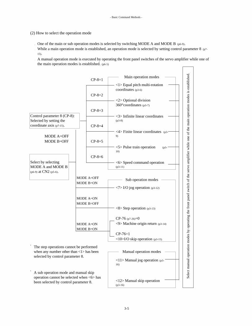
(2) How to select the operation mode
One of the main or sub operation modes is selected by switching MODE A and MODE B (p6-9).
CP-8=1
CP-8=2
CP-8=3
CP-8=4
MODE A=OFFMODE B=OFF CP-8=5
CP-8=6
MODE A=OFFMODE B=ON
<7> I/O jog operation (p3-12)
MODE A=ONMODE B=OFF
<8> Step operation (p3-13)
CP-76 (p7-26)=0MODE A=ON <9> Machine origin return (p3-14)
MODE B=ONCP-76=1<10>I/O skip operation (p3-15)
<11> Manual jog operation (p3-16)
<12> Manual skip operation (p3-16)
Control parameter 8 (CP-8): Selected by setting the coordinate axis (p7-15).
Select by selecting MODE A and MODE B (p6-9) at CN2 (p5-6).
<5> Pulse train operation (p3-10)
<4> Finite linear coordinates (p3-9)
<6> Speed command operation (p3-11)
Sub operation modes
Sele
ct m
anua
l ope
ratio
n m
odes
by
oper
atin
g th
e fr
ont p
anel
sw
itch
of th
e se
rvo
ampl
ifie
r w
hile
one
of
the
mai
n op
erat
ion
mod
es is
est
ablis
hed.
While a main operation mode is established, an operation mode is selected by setting control parameter 8 (p7-
15).A manual operation mode is executed by operating the front panel switches of the servo amplifier while one of the main operation modes is established. (p6-5)
<1> Equal pitch multi-rotation coordinates (p3-6)
<2> Optional division 360°coordinates (p3-7)
Main operation modes
The step operations cannot be performed when any number other than <1> has been selected by control parameter 8.
A sub operation mode and manual skip operation cannot be selected when <6> has been selected by control parameter 8.
Manual operation modes
<3> Infinite linear coordinates (p3-8)
3-5

- Basic Command Methods -
(3) Detailed description of operation modes
<1> Equal pitch multi-rotation coordinates
• This mode is used for equal division and indexing to drive the ATC magazine, etc.•
•
Mode A (OFF) Main operation modes (p3-5) are selectedMode B (OFF) by mode A and mode B (p6-9).
Servo ON (p6-9): Supplies power to the servo actuator.
AD0
AD7
Start (p6-10): Positioning is executed when start is input.
Speed selection (p6-12):Two kinds of speeds and acceleration/deceleration time constants
Positioning completion (p6-19)
OUT-AD0
OUT-AD7
Sequ
ence
r inp
uts
Servo amplifier
The brake is automatically controlled in synchronization with the servo ON/OFF operations. (p5-14)
used for positioning can be set and selected. If the speed selections have not been allocated to controls 1 through 14 (p6-10), speed 1 for equal division and acceleration/deceleration time constant 1 will be selected.
Speed 1 for equal division: SP-7 (p7-10): Selected when the speed selection has been set to OFF.Speed 2 for equal division: SP-8 (p7-10): Selected when the speed selection has been set to ON.Acceleration/deceleration time constant 1: SP-9 (p7-11): Selected when the speed selection has been set to OFF.
The address nearest the current position is output as a binary number. (p6-20)
Home position (p6-23): This is set ON each time the positioning address is passed through.
Address numbers (p6-11) : Positioning addresses are each designated by a binary number.
Equal division and indexing are enabled simply by setting the total number of addresses, reduction gear ratio, etc.Use of the absolute encoder (p2-1) obviates the need for machine origin return despite the fact that infinite feed is enabled.
Operation ready command (p6-9): Supplies power to the main power supply.
Sequ
ence
r out
puts
Acceleration/deceleration time constant 2: SP-10 (p7-11): Selected when the speed selection has been set to ON.
Power save timer: When CP-39 (p7-21) is set, the servo lock is automatically switched over to brake hold after the time set in the parameter has elapsed.
B1,B2 brake control
Servo actuator : short-cut control enabled
Both absolute and incremental systems
supported
ATC magazine
3-6

- Basic Command Methods -
<2> Optional division 360° coordinates
This mode is used for positioning to any position using an index table, etc.
Mode A (OFF)Mode B (OFF)
Servo ON (p6-9): Supplies power to the servo actuator.
AD0
AD7
Start (p6-10): Positioning is executed when start is input.
Positioning completion (p6-19)
OUT-AD0
OUT-AD7
Fixed point/through point 1, 2 (p6-21)Sequ
ence
r inp
uts
Address numbers (p6-11): Positioning addresses from #1 to #255 are each designated by a binary number.
The target address is output as a binary number. (p6-20)
Address #1
Address #2
This signal is set ON when the servo actuator is at the position which has been set.
External failure input (p6-12): Causes the servo actuator to immediately stop, while maintaining its power.
Acceleration/deceleration time constant selection (p6-13): Two kinds of acceleration/deceleration time constants for positioning can be set and selected. If this signal does not select the acceleration/deceleration time constant, acceleration/deceleration time constant 1 will be selected.
Sequ
ence
r out
puts
Servo amplifier
Motor rotation speedPosition
Using the electronic gear, the position can be input using an angle ranging from 0 to 359.99···° without the need to take the reduction gear ratio into consideration. (p7-14,33)
Acceleration/deceleration time constant 1: SP-9 (p7-11)
Acceleration/deceleration time constant 2: SP-10 (p7-11)
The brake is automatically controlled in synchronization with the servo ON/OFF operations. (p5-14)
B1, B2 brake control
Use of the absolute encoder (p2-1) obviates the need for machine origin return (p3-14)
despite the fact that infinite feed is enabled.
Main operation modes (p3-5) are selected by mode A and mode B (p6-9).
Operation ready command (p6-9): Supplies power to the main power supply.
Servo actuator : short-cut control enabled
Torque limiting enable (p6-12): Controls the torque that enables the motor to be forcibly stopped by an external stopper.
Motor rotation speed
This can be set from address #1 up to address #255 in the 0 to 359.99···°
range. Input the motor rotational speed and position for each data.
Positioning data (p7-33)
Position
Both absolute and incremental systems
supported
3-7
- Basic Command Methods -
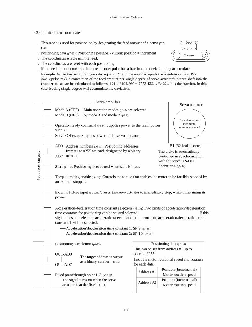
<3> Infinite linear coordinates
Positioning data (p7-33): Positioning position - current position = incrementThe coordinates enable infinite feed.The coordinates are reset with each positioning.If the feed amount converted into the encoder pulse has a fraction, the deviation may accumulate.
Servo actuator Mode A (OFF) Main operation modes (p3-5) are selectedMode B (OFF) by mode A and mode B (p6-9).
Servo ON (p6-9): Supplies power to the servo actuator.
AD0
AD7
Start (p6-10): Positioning is executed when start is input.
Acceleration/deceleration time constant 1: SP-9 (p7-11)
Acceleration/deceleration time constant 2: SP-10 (p7-11)
Positioning completion (p6-19)
OUT-AD0
OUT-AD7
Fixed point/through point 1, 2 (p6-21):
Servo amplifier
Sequ
ence
r out
puts
Torque limiting enable (p6-12): Controls the torque that enables the motor to be forcibly stopped by an external stopper.
External failure input (p6-12): Causes the servo actuator to immediately stop, while maintaining its power.
Motor rotation speed
Positioning data (p7-33)
Position (Incremental)Motor rotation speed
Acceleration/deceleration time constant selection (p6-13): Two kinds of acceleration/deceleration time constants for positioning can be set and selected. If this signal does not select the acceleration/deceleration time constant, acceleration/deceleration time constant 1 will be selected.
This mode is used for positioning by designating the feed amount of a conveyor, etc.
Operation ready command (p6-9): Supplies power to the main power supply.
Address numbers (p6-11): Positioning addresses from #1 to #255 are each designated by a binary number.
B1, B2 brake controlThe brake is automatically controlled in synchronization with the servo ON/OFF operations. (p5-14)
Example: When the reduction gear ratio equals 121 and the encoder equals the absolute value (8192 (2048 4)pulse/rev), a conversion of the feed amount per single degree of servo actuator’s output shaft into the encoder pulse can be calculated as follows: 121 x 8192/360 = 2753.422… “.422…” is the fraction. In this case feeding single degree will accumulate the daviation.
The signal turns on when the servo actuator is at the fixed point.
This can be set from address #1 up to address #255.Input the motor rotational speed and position for each data.
Position (Incremental)Address #1
Address #2
The target address is output as a binary number. (p6-20)
Both absolute and incremental
systems supported
Conveyor
3-8

- Basic Command Methods -
<4> Finite linear coordinates
It enables positioning at any position.Restrictions apply to the operation range. (p3-17)
The coordinate axes are linear coordinates.
Mode A (OFF)Mode B (OFF)
Servo ON (p6-9): Supplies power to the servo actuator.
AD0
AD7
Acceleration/deceleration time constant 1: SP-9 (p7-11)
Acceleration/deceleration time constant 2: SP-10 (p7-11)
Positioning completion (p6-19)
OUT-AD0
OUT-AD7
Fixed point/through point 1, 2 (p6-21)
Address numbers (p6-11): Positioning addresses from #1to #255 are each designated by a binary number.
B1, B2 brake control
Input the motor rotational speed and position for each data.
Address #1
Start (p6-10): Positioning is executed when start is input.
Positioning data (p7-33)
Address #2
Rotational restrictions apply to both the absolute and incremental encoders.
Motor rotation speed
Torque limiting enable (p6-12): Controls the torque that enables the motor to be forcibly stopped by an external stopper.
Position
The brake is automatically controlled in synchronization with the servo ON/OFF operations.(p5-14)
Acceleration/deceleration time constant selection (p6-13): Two kinds of acceleration/deceleration time constants for positioning can be set and selected.
If this signal does not select the acceleration/deceleration time constant, acceleration/deceleration time constant 1 will be selected.
The target address is output as a binary number. (p6-20)
This signal is set ON when the servo actuator is at the set position.
This can be set from address #1 up to address #255.
Servo actuator
Sequ
ence
r inp
uts
External failure input (p6-12): Causes the servo actuator to immediately stop, while maintaining its power.
This mode is used for optional positioning operations within the restricted ranges of the robot arm, rack & pinion, etc.
Main operation modes (p3-5) are selected by mode A and mode B (p6-9).
Operation ready command (p6-9): Supplies power to the main power supply.
Sequ
ence
r out
puts
Servo amplifier
PositionMotor rotation speed
Both absolute and incremental
systems supported
3-9

- Basic Command Methods -
<5> Pulse train operation
Supply the pulses from the sequencer. (p5-9)
The encoder signals can be output to the sequencer. (p5-9)
The current position can be sent to the sequencer by RS-232C communication. (p5-8,8-1)
Mode A (OFF)Mode B (OFF)
Servo ON (p6-9): Supplies power to the servo actuator.
5V Inputs pulses from the sequencer. (p5-9)
A-IN*A-INB-IN*B-IN0V
Torque limiting enable (p6-12) :Controls the torque that enables the motor to be forcibly stopped by an external stopper.
External failure input (p6-12) :Causes the servo actuator to immediately stop, while maintaining its power.
Positioning completion (p6-19)
A-OUTB-OUTZ-OUT0V
RS-232C The current position can be sent in real-time to the sequencer. (p5-8,8-1)
Rotation corresponds to the amount of pulses supplied. There are 2 pulse formats to choose from. (p7-18)
Main operation modes (p3-5) are selected by mode A and mode B (p6-9).
Operation ready command (p6-9): Supplies power to the main power supply.
Servo amplifier
Sequ
ence
r out
puts
There are 2 pulse formats to choose from. (p7-18)
B1, B2 brake control (p5-14)
Rotational restrictions apply to both the absolute and incremental encoders.
Servo actuator
Sequ
ence
r inp
uts
Motor rotationamount [Pulse] = No. of
pulses input
The A-, B- and Z-phase source signals of the encoder can be output to the sequencer. (p5-9)
x Electronic gear α (p7-14)
The brake is automatically controlled in synchronization with the servo ON/OFF operations.(p5-14)
Electronic gear β (p7-14)
Both absolute and incremental systems
supported
3-10

- Basic Command Methods -
<6> Speed command operation
This mode is used when controlling the speed of a press, etc.
Servo actuator
Mode A (OFF)Mode B (OFF)
Servo ON (p6-9): Supplies power to the servo actuator.
FWDRVS
CONT1-14 Servo parameter allocation SP
(p6-16) (p7-11)
Speed command Speed commandspeed selection 1 speed 1 Up to 6 motor rotation speeds can be set.
Speed command Speed commandspeed selection 2 speed 2
Speed command Speed commandspeed selection 3 speed 3
Speed command Speed commandspeed selection 4 speed 4
Speed command Speed commandspeed selection 5 speed 5
Speed command Speed commandspeed selection 6 speed 6
(p6-17) (p7-12)
Speed command acceleration/ Speed commanddeceleration selection 1 acceleration/deceleration 1
Speed command acceleration/ Speed commanddeceleration selection 2 acceleration/deceleration 2
Speed command acceleration/ Speed commanddeceleration selection 3 acceleration/deceleration 3
Sequ
ence
rin
puts
Sequ
ence
r out
puts
Servo amplifier
The servo actuator rotates. (p6-15)
Speeds are selected by speed command speed selection 1 through 6.Speed command speed 1 is automatically selected when speed command speed selections 1 through 6 have not been allocated to control 1 through 14.
External failure input (p6-12): Causes the servo actuator to be shut down immediately.
Up to 3 motor acceleration/ deceleration time constants can be set.
The acceleration/ deceleration time constant is selected by speed command acceleration/ deceleration selection 1, 2 or 3.
Speed command acceleration/ deceleration 1 is automatically selected when speed command acceleration/ deceleration selections 1 through 3 have not been allocated to control 1 through 14.
The operation speed is set in a parameter, and it is selected by a control input (p6-10).There are 6 speeds and 3 acceleration/deceleration time constants to choose from. (p6-17)
Rotational restrictions apply to both the absolute and incremental encoders.
Main operation modes (p3-5) are selected by mode A and mode B (p6-9).
Operation ready command (p6-9): Supplies power to the main power supply.
RS-232C (p5-8): Enables the command speed to be changed using the communication function.
Speed arrival (p6-23): This signal is set ON when the motor rotation speed exceeds the speed arrival identification speed CP-26 (p7-19) setting.
B1, B2 brake controlThe brake is automatically controlled in synchronization with the servo ON/OFF operations.(p5-14)
Both absolute and incremental systems
supported
Press
3-11

- Basic Command Methods -
<7> I/O jog operation
FWDRVS
Jog operation at a constant rotation speed can be performed using the control I/O signals (p5-6).
The I/O jog operations are controlled by position control. (p3-17)
Mode A (OFF)Mode B (ON)
Servo ON (p6-9): Supplies power to the servo actuator.
FWDRVS
The motor speed is set in the SP-4 manual feedrate (p7-10) parameter.
The main operation mode is switched to the I/O jog operation by switching mode A and mode B(p6-9).
The I/O jog mode is used as an auxiliary function (sub-operation mode) of the main operation modes (p3-3).
I/O jog operation is selected by mode A and mode B (p6-9).
Operation ready command (p6-9): Supplies power to the main power supply.
Servo amplifier
Sequ
ence
r out
puts B1, B2 brake control (p5-
14)
The motor acceleration/deceleration time constant is set in the SP-5 manual feed acceleration/deceleration time constant (p7-10) parameter.
Servo actuator
The brake is automatically controlled in synchronization with the servo ON/OFF operations. (p5-14)
Rotational restrictions apply to both the absolute and incremental encoders.
Sequ
ence
r inp
uts
The servo actuator rotates. (p6-15)
RS-232C (p5-8,8-1): Enables the command speed to be changed using the communication function.
Positioning completion (p6-19): Invalid when CP-8 (Coordinate axis) has been set to “1” (equal pitch multi-rotation coordinates.)
Speed arrival (p6-23): This signal is set ON when the motor rotation speed exceeds the speed arrival identification speed CP-26 (p7-19) setting.
External failure input (p6-12): Causes the servo actuator to immediately stop, while maintaining its power.
Both absolute and incremental
systems supported
3-12

- Basic Command Methods -
<8> Step operation Address #1 Address #2
•
• It is used for manually replacing the tools in the ATC magazine.• It can also be used for checking the positioning position. JOG•
•
•
Servo actuator Mode A (ON) Step operation is selected byMode B (OFF) mode A and mode B (p6-9).
Servo ON (p6-9): Supplies power to the servo actuator.
FWDRVS
The motor speed is set in the SP-4 manual feedrate (p7-10) parameter.
Positioning completion (p6-19)
The brake is automatically controlled in synchronization with the servo ON/OFF operations. (p5-14)
Sequ
ence
r inp
uts
Servo amplifier
Sequ
ence
r out
puts
The motor acceleration/deceleration time constant is set in the SP-5 manual feed acceleration/deceleration time constant (p7-10) parameter.
External failure input (p6-12): Causes the servo actuator to immediately stop, while maintaining its power.
Operation ready command (p6-9): Supplies power to the main power supply.
The servo actuator rotates. (p6-15)
( If the motor cannot stop at the above address because of the long deceleration time, it will stop at the address next to the predetermined one.)
B1, B2 brake control
This mode provides positioning to the nearest address after a jog operation.
It is used as an auxiliary function (sub-operation mode) of the equal pitch multi-rotation coordinates (p3-6).
Step operations cannot be performed at any coordinate axis other than at the equal pitch multi-rotation coordinates.The main operation mode (p3-5) is switched to the step operation by switching between mode A and mode B (p6-9).
Jog operationPositioned to the address that comes next to where jog operation goes OFF
Both absolute and incremental
systems supported
Positioned to
3-13
- Basic Command Methods -
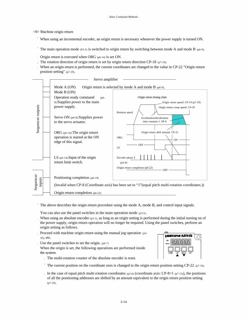
<9> Machine origin return
Origin return is executed when ORG (p6-14) is set ON.The rotation direction of origin return is set by origin return direction CP-18 (p7-19).
Mode A (ON) Origin return is selected by mode A and mode B (p6-9).Mode B (ON)
Origin return timing chart
Origin return speed: CP-19 (p7-19)
Origin return creep speed: CP-20
Rotation speed
ORG
LS
Encoder phase Z
(p5-9)
Origin return completion (p6-22)
Positioning completion (p6-19)
Origin return completion (p6-22)
You can also use the panel switches in the main operation mode (p3-5).
Use the panel switches to set the origin. (p6-7)
The multi-rotation counter of the absolute encoder is reset.
Acceleration/decelerationtime constant 1: SP-9
ORG (p6-14):The origin return operation is started at the ON edge of this signal.
LS (p6-14):Input of the origin return limit switch.
Origin return shift amount: CP-21
In the case of equal pitch multi-rotation coordinates (p3-6) (coordinate axis: CP-8=1 (p7-15)), the positions of all the positioning addresses are shifted by an amount equivalent to the origin return position setting (p7-19).
When using an absolute encoder (p2-1), as long as an origin setting is performed during the initial turning on of the power supply, origin return operation will no longer be required. Using the panel switches, perform an origin setting as follows.
The above describes the origin return procedure using the mode A, mode B, and control input signals.
Sequ
ence
rin
puts
(Invalid when CP-8 (Coordinate axis) has been set to “1”(equal pitch multi-rotation coordinates.))
OFF
When the origin is set, the following operations are performed inside the system.
The current position on the coordinate axes is changed to the origin return position setting CP-22 (p7-19).
Servo amplifier
Proceed with machine origin return using the manual jog operation (p3-
16), etc.
When using an incremental encoder, an origin return is necessary whenever the power supply is turned ON.
The main operation mode (P3-5) is switched to origin return by switching between mode A and mode B (p6-9).
When an origin return is performed, the current coordinates are changed to the value in CP-22 "Origin return position setting" (p7-19).
Sequ
ence
r out
puts
ON
OFF
Servo ON (p6-9):Supplies power to the servo actuator.
Operation ready command (p6-
9):Supplies power to the main power supply.
3-14

- Basic Command Methods -
<10> I/O Skip operation
The motor speed is set in the SP-4 manual feedrate (p7-10) parameter.
This operation mode is used for adjustment of machine origin.
Servo actuator Mode A (ON)Mode B (ON)
FWDRVS(p6-15)
Positioning completion (p6-19)
Set CP-76 (p7-26) sub operation mode switch from 0(default value) to 1, sub operation mode when MODE A,B=ON is changed from machine origin return to I/O skip operation (p3-5).
The brake is automatically controlled in synchronization with the servo ON/OFF operations. (p5-14)
Sequ
ence
r out
puts
The motor acceleration/deceleration time constant is set in the SP-5 manual feed acceleration/deceleration time constant (p7-10) parameter.
The servo motor rotation amount is set in the SP-6 skip amount parameter (unit = encoder pulses) (p7-10).
The servo actuator rotates by a amount set on SP-6 skip amount (p7-10).
B1, B2 brake control
External failure input (p6-12): Causes the servo actuator to immediately stop, while maintaining its power.
Operation ready command (p6-9):Supplies power to the main power supply.
Servo ON (p6-9):Supplies power to the servo actuator.
Set CP-76 (p7-26) sub operation mode switch from 0(default value) to 1
Sequ
ence
r in
puts
The servo actuator rotates by a fixed amount to the current position incrementing direction when FWD (p6-15) is ON.
The servo actuator rotates by a fixed amount to the current position decrementing direction when RVS (p6-15) is ON.
Servo amplifier
I/O skip is selected by mode A and mode B (p6-9).
This operation is invalid when CP-8 (Coordinate axis) has been set to “6” speed command operation.
Both absolute and incremental systems
supported
Skip
3-15

- Basic Command Methods -
<11> Manual jog operation
Jog operations are possible while no input signals (p6-9) are input.Operation is initiated by the panel switch. (p6-5)
Rotation is executed only while the switch is held down.Operation is possible even without connecting the CN2 control I/O signal connector (p5-6).
? ?
The motor rotates at the SP-4 manual feedrate (p7-10) setting. CN2
<12> Manual skip operation
Skip operations are possible while no input signals (p6-9) are input.Operation is initiated by the panel switch. (p6-6)
Rotation by a prescribed angle is executed only by pressing the switch once.Operation is possible even without connecting the CN2 control I/O signal connector (p5-6).
? ?
CN2
The motor rotates at the SP-4 manual feedrate (p7-10) setting.
For details on the rotational direction of the actuator output axis, refer to the section on the "input signals, parameters and servo actuator rotational directions (p3-26)".
The motor accelerates and decelerates according to the setting of the SP-5 manual feed acceleration/deceleration time constant (p7-10).
SETDOWN
The servo actuator rotates by a fixed amount to the current position incrementing direction.
The servo motor rotation amount is set in the SP-6 skip amount parameter (unit = encoder pulses) (p7-10).
UP
The servo actuator rotates by a fixed amount to the current position decrementing direction.
UP
MODE
Servo actuator rotates to the current position decrementing direction while DOWN switch is held down.
Servo actuator rotates to the current position incrementing direction while UP switch is held down.
The motor accelerates and decelerates according to the setting of the SP-5 manual feed acceleration/deceleration time constant (p7-10).
SETMODE DOWN
For details on the rotational direction of the actuator output axis, refer to the section on the" input signals, parameters and servo actuator rotation directions (p3-26)".
Manual jog
Skip
3-16

- Basic Command Methods -
(4)
? Operations marked with the black dot can be performed.
Example:
MODE MODEA B
*2*4
Speed control
I/O jog operation OFF ON - ? ? ? ? ? -Step operation ON OFF - ? - - - - -
I/O skip 1 ? ? ? ? ?
- ? ? ? ? ? ?
- ? ? ? ? ? -
? ? ? - - ?? ? - - - -- - - ? ? ? *3- - - ? ? -1 2 3 4 5 6
-Abso-
luteIncre- mental
Absol- ute
- -
*1:
*2: CP = Control parameter (p7-13)
*3: The “AL-15” (overflow) (p9-3) is displayed when the power is turned ON again.*4:
Func
tiona
l res
tric
tions
Encoder typeUnidirectional infinite rotation
Short-cut controlAbsolute encoder limit stop (*1)
Incremental encoder limit stop (*1)
Manual jog operation
Machine origin return ON ON
Position control
Main operation mode (p3-5)
Infi
nite
line
ar c
oord
inat
es
Fini
te li
near
coo
rdin
ates
Puls
e tr
ain
oper
atio
n
Spee
d co
mm
and
oper
atio
n
Opt
iona
l div
isio
n 36
0°
coor
dina
tes
Equ
al p
itch
mul
ti-ro
tatio
n co
ordi
nate
s
Position data type
Input statuses of modes
A, B
Posi
tion
cont
rol
OFF OFF
Manual skip operation
CP-
76
Coordinate axis: CP-8 (*2) (p7-15)
Sub operation
mode
Manual operation
mode
In any mode marked with a white dot ? , the servo actuator is stopped by the alarm detection (of an overflow) when the motor shaft has rotated through ±32767 rotations or more centering on the origin.
Sub operation mode when MODE A,B are both ON is selected from machine origin return or I/O skip operation by CP-76 (p7-26).
Main operation modes, and selectable sub operation modes and manual operation modes
Pulse train operation is set as the main operation mode when "5" is selected as the coordinate axis CP-8 (p7-15) setting.When both modes A and B (p6-9) are set OFF, pulse train operation (p3-10) can be performed in the main operation mode (p3-5).When mode A is set OFF and mode B is set ON in this state, I/O jog operation (p3-12) is performed.Step operation (p3-13) cannot be performed when the main operation mode has been set to pulse train operation.
Absolute / Incremental
0 ? -? ? ? ?
3-17

- Basic Command Methods -
(5) Correlation between operation modes and control input signals
PRDY 36 ? ? ? ? ? ? ? ? ? ? - -
SVON 35 ? ? ? ? ? ? ? ? ? ? - -MODE A 24 ? ? ? ? ? ? ? ? ? ? - -MODE B 25 ? ? ? ? ? ? ? ? ? ? - -START 22 ? ? ? ? - - - - - - -RESET 40 ? ? ? ? ? ? ? ? ? ? - -
CONT1-14 * ? ? ? ? ? ? ? ? ? ? - -
(6) Correlation between operation modes and control output signals
? : The signal is not output in the equal pitch multi-rotation coordinates mode.
INP 31 ? ? ? ? ? - ? ? ? ? - -
OUT1-15 * ? ? ? ? ? ? ? ? ? ? - -BAT ALM 46 6-24 ? ? ? ? ? ? ? ? ? ? ? ?
* : See p5-6
6-9
6-10
6-19
Man
ual s
kip
oper
atio
n
I/O
jog
oper
atio
n
Step
ope
ratio
n
Puls
e tr
ain
oper
atio
n
Spee
d co
mm
and
oper
atio
n
Symbol
CN
2 pi
n nu
mbe
r. (p
5-6)
Ref
eren
ce p
age
Equ
al p
itch
mul
ti-ro
tatio
n co
ordi
nate
sOperation ready
command
Servo ONMode A
Manual operation
mode
Mac
hine
ori
gin
retu
rn
Man
ual j
og o
pera
tion
Main operation mode
Opt
iona
l div
isio
n36
0° c
oord
inat
es
Infi
nite
line
ar c
oord
inat
es
Fini
te li
near
coor
dina
tes
Positioning completion
Output 1-15Battery alarm
Sub operation mode
I/O
ski
p op
erat
ion
Mode BStartReset
Control 1-14
Signal
3-18

- Basic Comand Methods -
(7) Correlation between operation modes and servo parameters
Equ
al p
itch
mul
ti-ro
tatio
n co
ordi
nate
s
Opt
iona
l div
isio
n36
0° c
oord
inat
es
Infi
nite
line
ar
coor
dina
tes
Fini
te li
near
coor
dina
tes
Puls
e tr
ain
oper
atio
n
Spee
d co
mm
and
oper
atio
n
I/O
jog
oper
atio
n
Step
ope
ratio
n
Mac
hine
ori
gin
retu
rn
I/O
ski
p op
erat
ion
Man
ual j
og
Man
ual s
kip
1 Speed loop proportional gain ? ? ? ? ? ? ? ? ? ? ? ?
2 Speed loop integral gain ? ? ? ? ? ? ? ? ? ? ? ?
3 Position loop gain ? ? ? ? ? - ? ? ? ? ? ?
4 Manual feedrate - - - - - - ? ? - ? ? ?
5Manual feed
acceleration/deceleration time constant
- - - - - - ? ? - ? ? ?
6 Skip amount - - - - - - - - - ? - ?
7 Speed 1 for equal division ? - - - - - - - - - - -
8 Speed 2 for equal division ? - - - - - - - - - - -
9Acceleration/deceleration
time constant 1? ? ? ? - - - - ? - - -
10Acceleration/deceleration
time constant 2? ? ? ? - - - - - - - -
11 Speed command speed 1 - - - - - ? - - - - - -
12 Speed command speed 2 - - - - - ? - - - - - -
13 Speed command speed 3 - - - - - ? - - - - - -
14 Speed command speed 4 - - - - - ? - - - - - -
15 Speed command speed 5 - - - - - ? - - - - - -
16 Speed command speed 6 - - - - - ? - - - - - -
17Speed command
acceleration/deceleration 1- - - - - ? - - - - - -
18Speed command
acceleration/deceleration 2- - - - - ? - - - - - -
19Speed command
acceleration/deceleration 3- - - - - ? - - - - - -
7-9
7-10
7-11
7-12
Manual operation
mode
Servo parameterNo.
Ref
eren
ce p
age
Main operation mode Sub operation mode
3-19

- Basic Comand Methods -
(8) Correlation between operation modes and control parameters
Equ
al p
itch
mul
ti-ro
tatio
n co
ordi
nate
s
Opt
iona
l div
isio
n36
0° c
oord
inat
es
Infi
nite
line
ar
coor
dina
tes
Fini
te li
near
coor
dina
tes
Puls
e tr
ain
oper
atio
n
Spee
d co
mm
and
oper
atio
n
I/O
jog
oper
atio
n
Step
ope
ratio
n
Mac
hine
ori
gin
retu
rn
I/O
ski
p op
erat
ion
Man
ual j
og
Man
ual s
kip
1 Encoder type ? ? ? ? ? ? ? ? ? ? ? ?
2Reduction gear ratio
numerator? ? - - - - - - - - - -
3Reduction gear ratio
denominator? ? - - - - - - - - - -
4 Electronic gear a - ? ? ? ? - - - - - - -
5 Electronic gear ß - ? ? ? ? - - - - - - -
6 Unit amount - ? ? ? - - - - - - - -
7 Brake available / unavailable ? ? ? ? ? ? ? ? ? ? ? ?
8 Coordinate axis ? ? ? ? ? ? ? ? ? ? ? ?
9 Number of divisions ? - - - - - - ? - - - -
10 Total number of addresses ? - - - - - - ? - - - -
11Optional division short-cut
control- ? - - - - - - - - - -
12Indexing number
incrementing direction? - - - - - - - - - - -
13MF/FIN available /
unavailable? - - - - - - - - - - -
14Short-cut/unidirectional
selection? - - - - - - - - - - -
152-position indexing direction
selection7-17 ? - - - - - - - - - - -
16 Input pulse system 7-18 - - - - ? - - - - - - -
? : Valid only for the equal pitch multi-rotation coordinates.: Invalid during the pulse train and speed command operations.? : Valid only for the finite linear coordinates and the pulse train operation.? : Invalid during the equal pitch multi-rotation operations.: Invalid during the finite linear operations.
7-13
7-14
7-15
7-16
Manual operation
mode
Control parameterNo.
Ref
eren
ce p
age
Main operation mode Sub operation mode
3-20

- Basic Comand Methods -
Equ
al p
itch
mul
ti-ro
tatio
n co
ordi
nate
s
Opt
iona
l div
isio
n36
0° c
oord
inat
es
Infi
nite
line
ar
coor
dina
tes
Fini
te li
near
coor
dina
tes
Puls
e tr
ain
oper
atio
n
Spee
d co
mm
and
oper
atio
n
I/O
jog
oper
atio
n
Step
ope
ratio
n
Mac
hine
ori
gin
retu
rn
I/O
ski
p op
erat
ion
Man
ual j
og
Man
ual s
kip
17Pulse train operation rotation
direction7-18 - - - - ? - - - - - - -
18 Origin return direction - - - - - - - - ? - - -
19 Origin return speed - - - - - - - - ? - - -
20 Origin return creep speed - - - - - - - - ? - - -
21 Origin return shift amount ? ? ? ? ? - - - ? - - -
22 Origin return position setting ? ? ? ? ? - - - ? - - -
23 Origin detection range ? ? ? ? ? - - - - - -
24 Positioning completion width ? ? ? ? ? - ? ? ? ? - -
25 Excessive deviation width ? ? ? ? ? - ? ? ? ? ? ?
26 Speed arrival identification speed
? ? ? ? ? ? ? ? ? ? - -
27Fixed point/through point
detection pattern- ? ? ? - - - - - - - -
28Fixed point/through point
detection position 1- ? ? ? - - - - - - - -
29Fixed point/through point
detection position 2- ? ? ? - - - - - - - -
30 Fixed point detection range - ? ? ? - - - - - - - -
31 Soft + over-travel detection position
- - - ? ? - - - ? - - -
32 Soft - over-travel detection position
- - - ? ? - - - ? - - -
33 Speed limit value ? ? ? ? - ? ? ? ? ? ? ?
34 Torque limit value ? ? ? ? ? ? ? ? ? ? - -
35 Brake forcible release ? ? ? ? ? ? ? ? ? ? - -
? : Valid only for the equal pitch multi-rotation coordinates.: Invalid during the pulse train and speed command operations.? : Valid only for the finite linear coordinates and the pulse train operation.? : Invalid during the equal pitch multi-rotation operations.: Invalid during the finite linear operations.
7-19
7-20
Manual operation
mode
Control parameterNo.
Ref
eren
ce p
age
Main operation mode Sub operation mode
3-21

- Basic Comand Methods -
Equ
al p
itch
mul
ti-ro
tatio
n co
ordi
nate
s
Opt
iona
l div
isio
n36
0° c
oord
inat
es
Infi
nite
line
ar
coor
dina
tes
Fini
te li
near
coor
dina
tes
Puls
e tr
ain
oper
atio
n
Spee
d co
mm
and
oper
atio
n
I/O
jog
oper
atio
n
Step
ope
ratio
n
Mac
hine
ori
gin
retu
rn
I/O
ski
p op
erat
ion
Man
ual j
og
Man
ual s
kip
36Home position detection
range? - - - - - - - - - - -
37Backlash compensation
amount? - - - - - - - - - - -
38Backlash compensation
direction? - - - - - - - - - - -
39 Power save timer available/unavailable
? - - - - - - - - - - -
40 Power save timer time ? - - - - - - - - - - -
41 Overshoot amount ? - - - - - - - - - - -
42 Number of follow-up pulses ? - - - - - - - - - - -
43 Interlock logic ? ? ? ? - - ? - - - -
44 Rewriting prohibited ? ? ? ? ? ? ? ? ? ? ? ?
45 Monitor selection ? ? ? ? ? ? ? ? ? ? ? ?
46Display contents when
power is turned ON7-24 ? ? ? ? ? ? ? ? ? ? ? ?
Control / no function designated
? ? ? ? ? ? ? ? ? ? - -
Control/AD0 ? ? ? ? - - - - - - - -
Control/AD1 ? ? ? ? - - - - - - - -
Control/AD2 ? ? ? ? - - - - - - - -
Control/AD3 ? ? ? ? - - - - - - - -
Control/AD4 ? ? ? ? - - - - - - - -
Control/AD5 ? ? ? ? - - - - - - - -
Control/AD6 ? ? ? ? - - - - - - - -
? : Valid only for the equal pitch multi-rotation coordinates.: Invalid during the pulse train and speed command operations.? : Valid only for the finite linear coordinates and the pulse train operation.? : Invalid during the equal pitch multi-rotation operations.: Invalid during the finite linear operations.
7-22
7-23
7-25
47-6
0
7-21
Manual operation
mode
Control parameterNo.
Ref
eren
ce p
age
Main operation mode Sub operation mode
3-22

- Basic Comand Methods -
Equ
al p
itch
mul
ti-ro
tatio
n co
ordi
nate
s
Opt
iona
l div
isio
n36
0° c
oord
inat
es
Infi
nite
line
ar
coor
dina
tes
Fini
te li
near
coor
dina
tes
Puls
e tr
ain
oper
atio
n
Spee
d co
mm
and
oper
atio
n
I/O
jog
oper
atio
n
Step
ope
ratio
n
Mac
hine
ori
gin
retu
rn
I/O
ski
p op
erat
ion
Man
ual j
og
Man
ual s
kip
Control/AD7 ? ? ? ? - - - - - - - -
Control / P operation ? ? ? ? ? ? ? ? ? ? - -
Control/ torque limiting enable
? ? ? ? ? ? ? ? ? ? - -
Control/ external failure input
? ? ? ? ? ? ? ? ? ? - -
Control/ speed selection ? - - - - - - - - - - -
Control/ acceleration/ deceleration time constant
selection- ? ? ? - - - - - - - -
Control / + over-travel ? ? ? ? ? ? ? ? ? ? - -
Control / - over-travel ? ? ? ? ? ? ? ? ? ? - -
Control/ORG - - - - - - - - ? - - -
Control/LS - - - - - - - - ? - - -
Control/FWD - - - - - ? ? ? - ? - -
Control/RVS - - - - - ? ? ? - ? - -
Control/ speed command speed selection 1
- - - - - ? - - - - - -
Control/ speed command speed selection 2
- - - - - ? - - - - - -
Control/ speed command speed selection 3
- - - - - ? - - - - - -
Control/ speed command speed selection 4
- - - - - ? - - - - - -
Control/ speed command speed selection 5
- - - - - ? - - - - - -
? : Valid only for the equal pitch multi-rotation coordinates.: Invalid during the pulse train and speed command operations.? : Valid only for the finite linear coordinates and the pulse train operation.? : Invalid during the equal pitch multi-rotation operations.: Invalid during the finite linear operations.
47-6
0Manual
operation mode
Control parameterNo.
Ref
eren
ce p
age
Main operation mode Sub operation mode
7-25
3-23

- Basic Comand Methods -
Equ
al p
itch
mul
ti-ro
tatio
n co
ordi
nate
s
Opt
iona
l div
isio
n36
0° c
oord
inat
es
Infi
nite
line
ar
coor
dina
tes
Fini
te li
near
coor
dina
tes
Puls
e tr
ain
oper
atio
n
Spee
d co
mm
and
oper
atio
n
I/O
jog
oper
atio
n
Step
ope
ratio
n
Mac
hine
ori
gin
retu
rn
I/O
ski
p op
erat
ion
Man
ual j
og
Man
ual s
kip
Control/ speed command speed selection 6
- - - - - ? - - - - - -
Control/ speed command acceleration/deceleration
selection 1- - - - - ? - - - - - -
Control/ speed command acceleration/deceleration
selection 2- - - - - ? - - - - - -
Control/ speed command acceleration/deceleration
selection 3- - - - - ? - - - - - -
Control/interlock ? ? ? ? - - ? - - - -
Out/ no function designated ? ? ? ? ? ? ? ? ? ? - -
Out/OUT-AD0 ? ? ? ? - - ? ? - ? - -
Out/OUT-AD1 ? ? ? ? - - ? ? - ? - -
Out/OUT-AD2 ? ? ? ? - - ? ? - ? - -
Out/OUT-AD3 ? ? ? ? - - ? ? - ? - -
Out/OUT-AD4 ? ? ? ? - - ? ? - ? - -
Out/OUT-AD5 ? ? ? ? - - ? ? - ? - -
Out/OUT-AD6 ? ? ? ? - - ? ? - ? - -
Out/OUT-AD7 ? ? ? ? - - ? ? - ? - -
Out/ operation ready completion
? ? ? ? ? ? ? ? ? ? - -
Out/servo ON/OUT ? ? ? ? ? ? ? ? ? ? - -
Out/operation underway ? - - - - - ? ? - ? - -
? : Valid only for the equal pitch multi-rotation coordinates.: Invalid during the pulse train and speed command operations.? : Valid only for the finite linear coordinates and the pulse train operation.? : Invalid during the equal pitch multi-rotation operations.: Invalid during the finite linear operations.
47-6
061
-75
Manual operation
mode
Control parameterNo.
Ref
eren
ce p
age
Main operation mode Sub operation mode
7-25
7-26
3-24

- Basic Comand Methods -
Equ
al p
itch
mul
ti-ro
tatio
n co
ordi
nate
s
Opt
iona
l div
isio
n36
0° c
oord
inat
es
Infi
nite
line
ar
coor
dina
tes
Fini
te li
near
coor
dina
tes
Puls
e tr
ain
oper
atio
n
Spee
d co
mm
and
oper
atio
n
I/O
jog
oper
atio
n
Step
ope
ratio
n
Mac
hine
ori
gin
retu
rn
I/O
ski
p op
erat
ion
Man
ual j
og
Man
ual s
kip
Out/ fixed point/ through point 1
- ? ? ? - - - - - - - -
Out/ fixed point/ through point 2
- ? ? ? - - - - - - - -
Out/ over-travel detection ? ? ? ? ? ? ? ? ? ? - -
Out/ origin return completion ? ? - ? ? - ? - -
Out/ alarm detection ? ? ? ? ? ? ? ? ? ? - -
Out/ speed arrival ? ? ? ? ? ? ? ? ? ? - -
Out/ home position ? - - - - - ? ? - ? - -
Out/torque limiting underway
? ? ? ? ? ? ? ? ? ? - -
Out/ positioning completion ? ? ? ? ? - ? ? ? ? - -
76 Sub operation mode switch ? ? ? ? ? - - - ? ? - -
77Factory use
(not for users)- - - - - - - - - - - -
78Position defect alarm available / unavailable
? - - - - - ? ? ? ? - -
79 Position defect alarm width ? - - - - - ? ? ? ? - -
? : Valid only for the equal pitch multi-rotation coordinates.: Invalid during the pulse train and speed command operations.? : Valid only for the finite linear coordinates and the pulse train operation.? : Invalid during the equal pitch multi-rotation operations.: Invalid during the finite linear operations.
61-7
5
7-26
7-27
Manual operation
mode
Control parameterNo.
Ref
eren
ce p
age
Main operation mode Sub operation mode
3-25

- Basic Command Methods -
(9) Input signals, parameters and servo actuator rotation directions
Control parameter
No.
Reference page
Setting, operation
- CCW CW- CW CCW- Install in CCW direction. Install in CW direction.- Install in CW direction. Install in CCW direction.
- 7-18 *1 CCW CW
? CCW CW? CW CCW? CCW CW? CW CCW
1 (default value) CCW CW
2 CW CCW
1 (default value) - -2 CCW CW3 CW CCW
Address #1 Address #1CCW CW
Address #2 Address #2CW CCW
Address #1 Address #1Address #1 Address #1
CW CCWAddress #2 Address #2
CCW CWAddress #1 Address #1
1 (default value) CCW CW2 CW CCW
Positive value Coordinate axis zero point moves in CW direction.
Coordinate axis zero point moves in CCW direction.
Negative value Coordinate axis zero point moves in CCW direction.
Coordinate axis zero point moves in CW direction.
31 -Set the position in the CCW
direction.Set the position in the CW
direction.
32 -Set the position in the CW
direction.Set the position in the CCW
direction.
1 (default value) CCW CW
2 CW CCW
- 7-33 - CCW direction is the increment direction.
CW direction is the increment direction.
6-13
7-16
7-19
7-20
FWDRVS
Name
6-15
37 7-21
12
14
18
7-17
-
Soft -overtraveldetection position
2-position indexingdirection selection
Soft +overtraveldetection position
Origin returnposition setting
Manual skip operation
Origin return direction
Position data
15
A , B
22
+ over-travel- over-travel
Pulse train operation
Manual jog operation
Backlash compensation
direction
47-60
C , S , F , H
Servo actuator type indication (p2-1)
2
1 (default value)
Indexing number
incrementing direction
Short-cut/unidirectiona
l selection
Input signal / parameter
- 6-6
6-5
3-26

- Basic Command Methods -
*1
The motor rotation direction is the same for servo actuator type displays C, S, F and H.
As seen from this direction
The specifications in this section apply when the servo actuator and motor are seen from the direction shown in the figure below.
The rotation direction for the pulse train input signals is the rotation direction when the "current position incrementing direction pulses" shown in the figure provided for the "input pulse system" on page 7-18 have been input. For this reason, the "input pulse system CP-16" and "pulse train operation rotation direction CP-17" are interrelated. (refer to page 7-18)
(Rotating direction of motor installed in a servo actuator and output shaft of a servo actuator is not always the same.)
3-27

- Installation -
4-1 Servo Actuator
WARNING:
Use of another size bolt could lead to serious injury.
WARNING:
CAUTION:
(1) Servo actuator mounting direction
The servo actuator can be mounted either horizontally or perpendicularly.
(2) Tightening torque and allowable transmission torque for mounting bolts
<1> Use hexagon socket head bolts for installation.<2> Tighten the mounting bolts with the tightening torque values shown on the following page.
Specifications of bolts used JIS: Japanese Industrial StandardsScrew
JIS B 0205 6g or class 2JISB 1051 12.9JISB 1176
4. INSTALLATION
Hexagon socket head bolt Class of strength
Hang the servo actuator with a hanger bolt when installing, removing or transferring the servo actuator so that it will not drop.Use the hanger bolt with the nominal diameter specified in "11. EXTERNAL DIMENSIONS".
When using aluminum or other materials, re-examine the tightening torque and transmission torque carefully.
The type of machine to which the servo actuator is installed, its setup environment, and the mass and torque of the servo actuator must be carefully considered when designating the dimensions and materials for the section to which the servo actuator is installed and the installation method. If this instruction is ignored, the servo actuator can drop and may cause serious personal injury.
Keep excess water and oil away from the servo actuator. Also, do not allow water and oil to enter the connectors along the cables. Ignoring these instructions could lead to damage to the servo system or electrical shock.
The table on the following page is applicable in cases where the other side is made of steel or cast iron.
Connect the wires from below in such a way that water or oil will not run along them and find its way inside the connectors.
4-1

- Installation -
Refer to page 2-1 for "Types A, B, C, F, S".
8-M8
3.8±0.19319±16
37.3±1.973.5±3.77.5±0.35
4-M10
8-M6
-
4-M10 4-M10
4-M8
8-M12 -
4-M10
-
4-M10
9-M12
8-M10 12-M8
12-M12 12-M12
9-M16
6-M12
Rotary part
Fixed part
4-M8
8-M12
Fixed part
Rotary part
Fixed part
Rotary part
12-M8
ARH24
8-M6
6-M8
6-M10
12-M12
8-M8
6-M10
Fixed part
ARH7
ARH17Fixed part
Rotary part
Fixed part
Rotary part
AR15
AR30
AR60
AR135
256
257
Model
A, B, F C, S
No. of bolts/size
Rotary part
Fixed part
Rotary part
3673600
128±6.413.1±0.65
4440
3.8±0.19
128±6.413.1±0.65128±6.4
37.3±1.93.8±0.1973.5±3.77.5±0.3537.3±1.93.8±0.19
10301051070
A, B, F C, S15.7±0.81.6±0.0837.3±1.9
107073.5±3.7
37.3±1.93.8±0.19
13.1±0.6573.5±3.77.5±0.35
128±6.413.1±0.6573.5±3.77.5±0.35128±6.4
13.1±0.6573.5±3.77.5±0.35
7.5±0.3515.7±0.81.6±0.08128±6.4
13.1±0.6537.3±1.93.8±0.19
32.5±1.62128±6.4
13.1±0.65-
-
-37.3±1.93.8±0.19
-73.5±3.77.5±0.35
--
73.5±3.77.5±0.35 315
3090243238025024501861820
1518149001315
1321290
70686
129005595480453
25101761730109
10927302782520
52105314440453
119001211
3090315
--
2450250
129001316
--
--
1290132
top : N.mbottom : kgf.m
top : N.mbottom : kgf.m
AR10HRotary part
Fixed part
6-M8
12-M61.6 0.08 191
37.3 1.9 884
15.7 0.8
Connectingpart
Types
18803.8 0.19 90
A, B, F C, S
Tightening torque Allowable transmission torque
4-2

- Installation -
(3) CenteringThe servo actuator is provided with a bearing for external load support.
(4) Conical spring washer
Name : Conical spring washerDenomination : Conical SW-2H-nominalMaterial : S50CM - S65CMHardness : HRC40 - 48Manufacturer : Heiwa Hatsujo Co., Ltd. (Japanese company)
[mm]
When the output shaft has an external support function, set the centering accuracy level to 30 µm to 50 µm.
Improper centering may cause damage to the bearing, output shaft, etc. inside the reduction gear.
2.824
0.61.01.21.51.8
2.31416
Use conical spring washers for use with hexagon socket heads to prevent looseness in the hexagon socket head bolts and protect the bolt seat surfaces from being marked.
14.616.9
D
Conical spring inside &outside diameters
13
12.6
8.4
H
0.851.251.55
t
5.25 8.5106.4
10.6
Nominal
d
1012
568
161821
1.92.22.52.0
4-3

- Installation -
4-2 Servo Amplifier
WARNING:
Only skilled technicians should perform these tasks.Attempts by nonqualified personnel could lead to electrical shock, injury, or fire.
(1)
Top
Bottom
(2) Installation space
Do not block the vents of the servo amplifier.
Heat <1> Heat
<3>
30 Volume [cm³]ARN15
Minimum volume of power board required
ARN30
Frame No.
<4>
The minimum volume of the power board required for heat dissipation is as below.
Inst
alla
tion
back
sur
face
<5>
50,000100,00030
100
250,000450,000
<2><3><4>
ARN135ARN6080
Above dimensions are common to all frame numbers.
<5>
To prevent electrical shock, be sure to turn off the power supply before beginning installation, removal or wiring of the machine.
Install the servo amplifier vertically to the ground so that the 7-segment LED display on the front panel is positioning horizontally.
Provide the clearances shown below to enable the heat to dissipate.
Provide the clearances shown below to enable the cables and connectors to be connected and routed.
<1>
Inst
alla
tion
surf
ace
Clearance dimensions [mm]
<2>
100
4-4
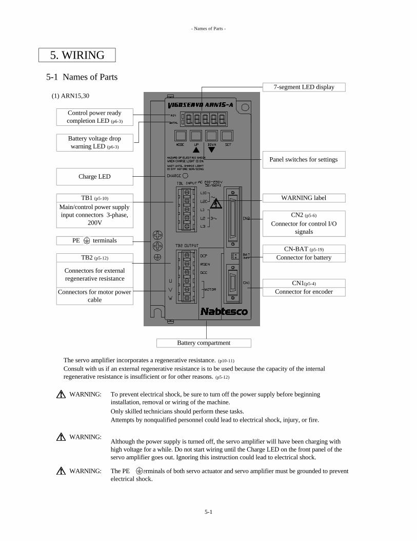
- Names of Parts -
5-1 Names of Parts
(1) ARN15,30
The servo amplifier incorporates a regenerative resistance. (p10-11)
WARNING:
Only skilled technicians should perform these tasks.Attempts by nonqualified personnel could lead to electrical shock, injury, or fire.
WARNING:
WARNING: The PE terminals of both servo actuator and servo amplifier must be grounded to prevent electrical shock.
PE terminals
TB2 (p5-12)
Connectors for external regenerative resistance
Connectors for motor power cable
CN1(p5-4)
Connector for encoder
Consult with us if an external regenerative resistance is to be used because the capacity of the internal regenerative resistance is insufficient or for other reasons. (p5-12)
To prevent electrical shock, be sure to turn off the power supply before beginning installation, removal or wiring of the machine.
Battery compartment
TB1 (p5-10)
Main/control power supply input connectors 3-phase,
200V
7-segment LED display
Panel switches for settings
WARNING label
CN2 (p5-6)
5. WIRING
Control power ready completion LED (p6-3)
Battery voltage drop warning LED (p6-3)
Charge LED
Although the power supply is turned off, the servo amplifier will have been charging with high voltage for a while. Do not start wiring until the Charge LED on the front panel of the servo amplifier goes out. Ignoring this instruction could lead to electrical shock.
Connector for control I/O signals
CN-BAT (p5-19)
Connector for battery
5-1

- Names of Parts -
•••For details, refer to page 7-23.
Absolute (ABS) encoder is the factorysetting.
Connector for pulse train I/O signals
TB3 (p5-14)
Connector for brake
Encoder selector switch
RS-232C connector
Set the switch to INC if the incremental encoder or AR10H is to be used. (p1-6,7)
Side panel
Bottom panel
CN4 (p5-9)
ABS INC
CN3 (p5-8)
Monitor connectorAch: Motor rotation speed monitorBch: Torque monitorCOM: Common
5-2

- Names of Parts -
ARN60,135
Absolute(ABS)encoder is the factory setting.Set the switch to INC if the incremental encoder is to be used. (p1-6)
WARNING:
COM:Common
The servo amplifier incorporates a regenerative resistance. (p10-11)
Although the power supply is turned off, the servo amplifier will have been charging with high voltage for a while. Do not start wiring until the Charge LED on the front panel of the servo amplifier goes out. Ignoring this instruction could lead to electrical shock.
Consult with us if an external regenerative resistance is to be used because the capacity of the internal regenerative resistance is insufficient or for other reasons. (p5-12,13)
CN4 (p5-9):Connector for pulse train I/O signals
CN3 (p5-8):RS-232C connector
TB3 (p5-14):Connector for brake
Control power ready completion LED (p6-3)
Battery compartment
CN1 (p5-4):Connector for encoder
CN-BAT (p5-19):Connector for battery
Battery voltage drop warning LED (p6-3)
connectors : single-phase,200V
Panel switches for settings
TB1:L1C,L2C (p5-13)
Control power supply input
TB1:U,V,W (p5-13)
Connectors for motor power cable
TB1:L1,L2,L3 (p5-13)
Main power supply inputconnectors : 3-phase,200V
PE terminals
TB1:DCP,RGEN,DCC (p5-13)
Connectors for external regenerative resistance
7-segment LED displayCharge LED
CN2 (p5-6):Connector for control I/O signals
Encoder selector switch
Monitor connector (p7-23)
Ach:Motor rotation speed monitorBch:Torque monitor
5-3

- Connector Pin Layout and Connections -
5-2 Connector Pin Layout and Connections
As seen from this direction
(1) Servo amplifier Cable
<1> CN1: Connector for encoder
Compatible plug type (made by Honda Tsushin Kogyo Co., Ltd.)
Plug: PCR-S20FS
Case: PCR-LS20LA1
Note: Do not connect a pin marked with "-".These pins may already be connected to the circuitry inside the servo amplifier.
All the pin layout diagrams show the connectors at the ends of the cables as seen from the cable end.
Connector at end of cable
16
PE
18 2012
19
*RTC 0V
9
BAT Z A B
*Z *A *B
15
14
10
5V 0V OH2RXD/TXD
RTC
11 13
9
5V 0V OH1 -*RXD/TXD
1 3 5
2 4 6
17
7
8
10
1 3 5 7
2 4 6
V0V OH2 U
18 20
*V *W *Z
Servo amplifier
Absolute encoder
Incremental encoder and AR10H
W Z A B
8
*B
12
PE
5V 0V OH1 - *U
5V
*A
14 16
5-4

- Connector Pin Layout and Connections -
Connection diagrams
AR10H (incremental encoder)
See wiring diagram on the left.
Perform the connections in accordance with the following specifications.
Wire : Twisted pair, multiple-wire shielded cable, 0.3 mm² cross-sectional area
Length : 20 m (contact us for a length of over 20 m)
5 V, 0 V wiring: Connect two wires in parallel as shown in the above figure to prevent voltage drops.
Incremental encoder (other than AR10H)Absolute encoder
AR10H do not have thermo switch in the motor.Connect OH1,OH2 pin5,6 CN1 at inside of CN1.If not , AL-2(Overheating of motor) (p9-1)
may occur at power on.
5-5

- Connector Pin Layout and Connections -
<2> CN2: Connector for control I/O signalsAs seen from this direction
Cable
Plug: PCR-S50FS Case: PCR-LS50LA
The default setting ( 7-25) is written in parentheses.
CO
NT
1(A
D 0
)C
ON
T 3
(AD
2)
CO
NT
5(A
D 4
)C
ON
T 7
(AD
6)
OU
T 1
(OU
T-A
D 0
)O
UT
3(O
UT
-AD
2)
OU
T 5
(OU
T-A
D 4
)
CO
NT
8(A
D 7
)C
ON
T 1
0(F
WD
)C
ON
T 1
1(I
nter
lock
)
CO
NT
2(A
D 1
)C
ON
T 4
(AD
3)
CO
NT
6(A
D 5
)
OU
T 2
(OU
T-A
D 1
)O
UT
4(O
UT
-AD
3)
OU
T 6
(OU
T-A
D 5
)
CO
NT
9(R
VS)
OU
T 8
(OU
T-A
D 7
)O
UT
10
(Hom
e po
sitio
n)O
UT
15
(Ope
ratio
n un
derw
ay)
CO
NT
13
(LS)
OU
T 1
2(S
ervo
ON
/OU
T)
OU
T 7
(OU
T-A
D 6
)O
UT
9(A
larm
det
ectio
n)
CO
NT
12
(Spe
ed s
elec
tion)
CO
NT
14
(OR
G)
Note: Do not connect a pin marked with "-".These pins may already be connected to the circuitry inside the servo amplifier.
Inpu
t com
mon
Out
put c
omm
on
MO
DE
B
Inpu
t com
mon
-
Out
put c
omm
on
MO
DE
A
STA
RT
24
- -
PRD
Y
RE
SET
BA
T A
LM
--
INP -
SVO
N
- - -
OU
T 1
3 (O
pera
tion
read
y co
mpl
etio
n)
OU
T 1
1 (O
rigi
n re
turn
co
mpl
etio
n)
OU
T 1
4 (F
ixed
po
int/t
hrou
gh p
oint
1)
Servo amplifier
Compatible plug type (made by Honda Tsushin Kogyo Co., Ltd.)
The terminals with white pin numbers like pin 1 are the control input terminals.
Connector at end of
cable
44 46
43 49
42
35 37
2218
38 4039 41 47
25
2 4 6 10 2012 14 1617 19 2115 231 3 5 7
32
9 11 13
36
834
45
5048
27 29 31 33
26 28 30
5-6

- Connector Pin Layout and Connections -
Input circuits
With plus common With minus common
Input circuit specifications Max. applied voltage : 26 VSupply current : 7 mA (at 24 V)
Output circuits
With plus common With minus common
Output circuit specifications Max. applied voltage : 30 VMax. supply current : 50 mA
Note:
Note:
Relay- +
Compatible with both plus common and minus common; all circuits insulated with photocouplers.
Take care not to connect the polarities in reverse since this will damage the servo amplifier.
Compatible with both plus common and minus common; all circuits insulated with photocouplers.
In the case of an inductive load (relay, etc.), a diode (with 240 V dielectric withstanding voltage or higher, 100 mA current or higher ) must always be connected in parallel with the load.
5-7

- Connector Pin Layout and Connections -
Power supply for I/O circuits
The power supply for the I/O circuits is to be provided by the customer.
DC 24 V ±10% , 1.2 A or higher
Note: Ground the PE terminal of the power supply.
Note:
Using one power supply for both purposes may give rise to malfunctioning.
Note:
<3> CN3: RS-232C connector
Compatible plug type (made by Hirose Electric Co., Ltd.)
Plug: HDEB-9P Case: HDE-CTH
The types of communication listed below are possible using the RS-232C connector.
Servo parameter readingServo parameter writingControl parameter readingControl parameter writingPositioning data readingPositioning data writingDisplay data readingInitialization
Note: CN3 is not isolated with the control circuit inside the servo amplifier. 0V terminal of equipment like personal computer may be connencted to the connector housing, frame, and PE terminal of AC power supply plug.
5V CTS RTS 0V
4
0V RXD
3 2
9 8 7 6
In this case, disconnect the PE termainal of the equipments or consult us.
If servo amplifier is connected to an equipment like this, Surge voltage between PE of equipment and PE of servo apmlifier may rush into the control circuit of servo amplifire and damage it.
Keep the power supply for the control I/O signals separate from the power supply for the brake (p5-14).
If certification under the European safety standards (p2-1) is to be obtained for the products, use power supplies (SELV : Safety extra low voltage) complying with the standards.
For more details on the communications specifications, refer to Section 8 communications (p8-1).
- TXD -
5 1
5-8

- Connector Pin Layout and Connections -
<4> CN4: Connector for pulse train I/O signals
Compatible plug type (made by Sumitomo 3M Co., Ltd.)Plug: 10114-3000VE Case: 10314-52A0
Pulse train input circuitWith an open collector With a line driver
Note : 5v, 0v are connected to the control circuit inside the servo amplifier, take care on the interface circuit so as not to rush in the serge current to the control cuicuit.
PE B-OUT - *B-IN
7
Input pin123
B-IN A-IN 0V
12
5V
6 4 2
7 5 3 1*A-IN 0V 5V
13 11
10 8Z-OUT A-OUT -
14
9
14
13
Signal name
A-IN*A-INB-IN
8
456
PE
Description
0 V
5 V This pin outputs a +5 V voltage.Maximum output current: 500 mA
5 V common
These are the pulse train input signal pins.Input signals to these pins to execute pulse train operations (p3-10).Interfacing with open collector and line driver is possible.
*B-IN
Z-OUTThey are used for feedback to the sequencer.Interface with an open collector output format.Maximum output current: 45 mA, maximum applied voltage: 30 V
This pin is connected inside the servo amplifier to the PE terminal (p5-1,3) of the chassis. Use it as the shielded ground of the signal cables.
These pins output the A-, B- and Z-phase pulse of the encoder.
90 phase difference Z: 1 pulse / motor one revolution
A, B: encorder pulse (p7-14) / motor one revolution11 A-OUT
12 B-OUT
5-9

- Connector Pin Layout and Connections -
<5> TB1(ARN15,30) : Connector for main/control power supply input
Compatible plug BLZ7.62/5/90 (made by Weidmüller)Terminal tightening torque 5.1kg cm
For information on the compatible solderless terminal, see the following page.
WARNING:
Only skilled technicians should perform these tasks.Attempts by nonqualified personnel could lead to electrical shock, injury, or fire.
Encoder A-, B- and Z-phase pulse output circuit
Note : 0v and open collector transistors are connected to the control circuit inside the servo amplifier, take care on the interface circuit so as not to rush in the serge current to the control cuicuit.
The figure on the right shows an example of the power supply connections.
To prevent electrical shock, be sure to turn off the power supply before beginning installation, removal or wiring of the machine.
Since the main power and control power are supplied separately, the main power can be turned off in a state in which the current operation information has been stored.
5 L3
Input pin
4 L23 L1
1 L1C2 L2C
1 2 3
Description
L1C L2C L1 L2
Signal name
3-phase 200-230 VAC for main power supply input +10% -15%
5
L3
4
Single-phase 200-230 VAC for control power supply input +10% -15%
5-10

- Connector Pin Layout and Connections -
A circuit breaker or fuse must be installed where the main power is led in.
Do not use quick-break fuses since they may melt when the power is turned on.
Cross-sectional area of conductors in cables used
Grounding
WARNING:
WARNING:
If the European safety standards (p2-1) are to be met, use parts which satisfy the EN60947-2 and EN60934 EN standards.
Main power cableL1, L2, L3
[mm²]
Grounding wire[mm²]
Capacity [A]
1015
Type
Make the ground cable 2 to 3 cm longer than L1, L2, and L3 and U,V, and W so that it will be the last to disconnect if either the main power cable or servo actuator power line is forcibly disconnected. Ignoring this instruction could lead to electrical shock.
Compatible solderless terminal main power cable and grounding
wire
ARN15ARN30
The PE terminals of both servo actuator and servo amplifier must be grounded to prevent electrical shock.
The H0.75/14 solderless terminal made by Weidmüller is compatible with control power cable when cross-section area of conductors in cables are 0.75mm2.
Control power cable[mm²]Type
Min. 1.25Min. 1.25 H1.5/14 (made by Weidmuller)
Min. 0.75
Capacity of circuit breaker, MCC, or fuse for main power supply
ARN15 Min. 0.75 Min. 0.75 H0.75/14 (made by Weidmuller)
ARN30
Control power cable
Main power cable
Make the groundingwires 2 to 3 cm longer.
PE terminals
Servo actuator power cable
5-11

- Connector Pin Layout and Connections -
<6> TB2(ARN15,30) : Connector for motor power cable/external regenerative resistance
Compatible plug type: BLZ7.62/6/90 (made by Weidmüller)Terminal tightening torque 5.1kg cm
Normal circumstances Use external regenerative resistance(Use internal regenerative resistance)
+ +
- -
Cross-sectional areas of motor power cable U, V, W and PE conductorsand compatible solderless terminal.
Regenerative transistor
External regenerative resistanceRGEN
DCC
DC280VDCC
UVW
RGEN
DCC
Figure out the regeneration capacity (refer to page 10-11). When the regenerative power is greater than the allowable value of the servo amplifier, an external regenerative resistance is required. In such cases, please consult with us.
3
56
DescriptionFor an external regenerative resistance. Short pins 2 and 3 under normal circumstances (when using an internal regenerative resistance).
For motor power cable; connect this with the U, V and W pins on the servo actuator.
Pins 2 and 3 are shorted under normal circumstances (when an internal regenerative resistance is used) using a conductor whose cross-sectional area is not less than 1.25 mm².
6
W
5
V
4
Input pin12
U
Signal nameDCP
RGEN
1 2
DCP
3
DCCRGEN
4
Cross-sectional area [mm²]Min 0.75Min 1.25
DCP
Regenerative transistor
Internal regenerative resistance
ARN15
DC280V
Circuitry inside servo amplifier
DCP
Internal regenerative resistance
ARN30
TypeH0.75/14(made by Weidmuller)Compatible solderless terminal
H1.5/14(made by Weidmuller)
Circuitry inside servo amplifier
5-12

- Connector Pin Layout and Connections -
<7> TB1(ARN60,135) : Connector for motor power cable/external regenerative resistanceTerminal tightening torque 12.7kg cm
A circuit breaker for the wiring or fuse must be installed where the main power is led in.
Cross-sectional area [mm2] of conductors in cables used
Cross-sectional areas of motor power cable U, V, W and PE conductorsand compatible solderless terminal.
Single-phase 200-230 VAC for control power supply input +10% -15%
L3 DCP RGEN DCC W
Type Capacity [A]
ARN60 20
U
L2C L1 L2
Signal name Description
U V
3-phase 200-230 VAC for main power supply input +10% -15%
DCP For an external regenerative resistance. Short RGEN and DCC under normal circumstances (when using an internal regenerative resistance).
RGENDCC
For motor power cable; connect this with the U, V and W pins on the servo actuator.V
W
Since the main power and control power are supplied separately, the main power can be turned off in a state in which the current operation information has been stored.
Type Main power cableR/S/T [mm²]
Grounding wire[mm²]
Compatible solderless terminal main power cable and grounding
Min. 3.5TMEV2-4(made by Nichifu)
ARN135 30
TMEV3.5-4(made by Nichifu)
ARN135 Min 3.5 TMEV3.5-4(made by Nichifu)
Cross-sectional area [mm²] Compatible solderless terminalARN60 Min 2.0 TMEV2-4(made by Nichifu)
Type
DCP and RGEN must be shorted under normal circumstances (when an internal regenerative resistance is used) using a conductor whose cross-sectional area is not less than 1.25 mm². (refer p5-12)
Capacity of circuit breaker, MCC, or fuse for main power supply
Figure out the regeneration capacity (refer to page 10-11). When the regenerative power is greater than the allowable value of the servo amplifier, an external regenerative resistance is required. In such cases, please consult with us.
Control power cable[mm²]
ARN60 Min. 2.0 Min. 2.0Min. 0.75
ARN135 Min. 3.5
5-13

- Connector Pin Layout and Connections -
<8> TB3: Connector for brake
Compatible plug type: BLZ5.08/4/90 (made by Weidmüller)Terminal tightening torque 5.1kg cm
Heat sink side
The brake incorporated in the servo actuator is exclusively for holding purposes.Do not use it to stop the motor while it is running.
The brake power must be released while the servo actuator is stopped.
B1 B2
The brake is engaged when an alarm (p9-1) occurs.
Use a power supply with stable DC output for the brake power supply.
B13
Input of power supply for holding electromagnetic brake
B2
21
Input pin
4
Compatible solderless terminal type: H0.75/14 made by Weidmüller, for 0.75 mm² cross-sectional area.
The power supply (DC 24 V) for the brake is to be provided by the customer. For details on the current capacity, refer to Section 2-2 with the Table of Specifications (p2-2).
B2
Output of power supply for holding electromagnetic brake
DescriptionSignal name24A24B
Circuit incorporated in servo amplifier
2 3
Turning OFF the 24 V power for the brake or turning OFF the servo ON signal while the servo actuator is still running will engage the holding brake, possibly wearing or damaging the brake's contact areas.
24A
1
Input pins 24A and 24B are nonpolar.
4
B124B
Switching noise from the motor power cable may be induced in the brake wiring, possibly giving rise to a high voltage.
Brake coil
If certification under the European safety standards (p2-1) is to be obtained for the products, use power supplies (SELV : Safety extra low votage) complying with the standards.
Provide a separate brake power supply, and do not use it as power supply for the control I/O signals (p5-7). Motor switching noise carried along the brake wiring may cause the control I/O signals to malfunction.
A surge absorber is wired inside the servo actuator in parallel with the brake in order to prevent surges when the brake is turned ON or OFF.
5-14
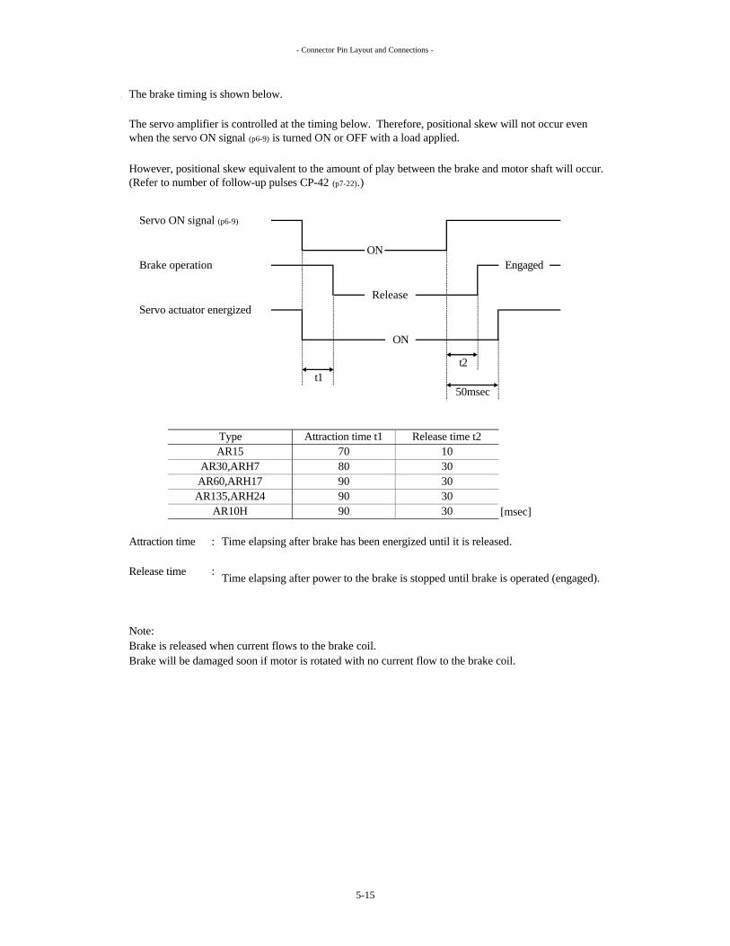
- Connector Pin Layout and Connections -
The brake timing is shown below.
t2t1
[msec]
Attraction time : Time elapsing after brake has been energized until it is released.
Release time :
Note:Brake is released when current flows to the brake coil.Brake will be damaged soon if motor is rotated with no current flow to the brake coil.
Time elapsing after power to the brake is stopped until brake is operated (engaged).
AR10H 90 30
Release
70
30
Attraction time t1
ON
50msec
Type
30
Release time t21030
AR135,ARH24
AR15AR30,ARH7
AR60,ARH17
ON
90
80
The servo amplifier is controlled at the timing below. Therefore, positional skew will not occur even when the servo ON signal (p6-9) is turned ON or OFF with a load applied.
90
However, positional skew equivalent to the amount of play between the brake and motor shaft will occur. (Refer to number of follow-up pulses CP-42 (p7-22).)
Servo actuator energized
Servo ON signal (p6-9)
Brake operation Engaged
5-15

- Connector Pin Layout and Connections -
(2) Servo actuator standard specifications (other than AR10H)
<1> Connector for servo actuator power cable
Compatible plug type Made by JAE Electronics, Inc.
<2> Connector for servo actuator encoder
Compatible plug type Made by JAE Electronics, Inc.
Absoluteencoderguide keyposition
Signal nameA
MS3106B20-29SZMS3106B20-29S
Straight plug
C*AB
D
*A
Absolute typeMS3057-12A
MS3108B20-29SZMS3108B20-29SIncremental type
Absolute type Incremental type
5 VPPE
A
W
N*W
PE
LM
T 0 V
R OH1S OH2
K *V
0 V
AB
A
CDEF
TS
M
HJ
R
*Z
B*B
*RXD/TXD
*BZ
B
RTC
G UH *U
RXD/TXD
J V
OH2
K *RTCL BAT
NP
OH1
0 V
5 V
F *ZZE
G
F
U
Signal name
B1 (brake)PE
WCDE
VAB
Signal name
MS3108B20-15SMS3108B24-10S
E B1 (brake)
Signal nameA UB V
L-type plugMS3108B14S-6SMS3108B16S-1S
AR15AR30, ARH7
Cable clampStraight plugMS3106B14S-6SMS3106B16S-1S
MS3057-6AMS3057-8A
G -
Cable clamp
AR30-135, ARH7-24
F B2 (brake)
C WD PE
Incremental encoderguide key position
For AR15
MS3057-12A
L-type plug
B2 (brake)
MS3057-16AMS3106B20-15SMS3106B24-10S
AR60, ARH17AR135, ARH24
5-16

- Connector Pin Layout and Connections -
(3) Servo actuator specifications for meeting UL and EN standards (other than AR10H)
The connector for the encoder is the same one as for the standard specifications.(Refer to Section 11 on external dimensions in page 11-1.)
<1> Connector for servo actuator power cable
Compatible plug type Made by JAE Electronics, Inc.
<2> Connector for servo actuator brake
Compatible plug type Made by HIROSE Electric Inc.
JL04-2022CK(14)
L-type plugAR15
Cable clampStraight plug
JL04-18CK(13)AR30, ARH7
JL04V-8A18-10SE-EB JL04V-6A18-10SE-EB
AR60, ARH17
A B1 (brake)
JL04V-8A22-22SE-EB JL04V-6A22-22SE-EB
Signal name
W
B
Signal name
PE
ABCD
U
B2 (brake)
V
In the case of specifications for meeting UL and EN standards, separate connectors--one for the U, V, W and PE signals and one for the B1 and B2 signals--are used.
Straight plug
H/M3106A10SL-4S
Cable clamp
H/MS3057-4A
L-type plug
H/MS3108B10SL-4SCommon toall types
AR135, ARH24
5-17

- Connector Pin Layout and Connections -
AR10H
<1> Compatible plug type Made by AMP
<2> Pin assignment
Power cable
? As seen from this direction
Encoder cable
? As seen from this direction
Brake cable
? As seen from this direction
140V
15PE
11W
12*W
6*Z
7U
A2
*A3B
170362-1170361-1
1 4 5
1U
2V
170360-1170359-1
Cap172159-1
172157-1172163-1
3W
4PE
B1
*B Z10*V
8*U
9V
2B2
PlugServo actuator side Cable side
135V
1
Pin SocketPower cable 172167-1 170360-1 170362-1
Brake cable 172165-1Encoder cable 172171-1
5-18

- Battery -
5-3 Battery
A lithium battery is used to back up the data of the absolute encoder.
(1) Recommended battery and connector type
The following battery is recommended.
Name: Lithium battery (made by Toshiba Denchi Co., Ltd.)
Type: ER17500V C (with connector)
Ratings: 3.6 V, 2700 mAh
Connector specificationsHousing: IL-2S-S3(N)Contact: IL-C2-1Made by JAE Electronics, Inc.
No battery is required if an incremental encoder (p1-6,1-7,2-1) is used for the servo actuator.
(2) Concerning replacement of the battery
<1>
<2>
<3>
<4> Replace the battery quickly.The data is retained only about 30 minute with control power off and battery not connected.
WARNING:
Do not heat the battery to 100 °C or above (Do not incinerate the battery).Ignoring this instruction could lead to ignition, combustion and explosion.
Do not re-charge the battery. Ignoring this instruction could lead to explosion or leakage.Contact of the eyes with battery contents could lead to loss of eyesight.
Do not disassemble the battery. Contact of the eyes with battery contents could lead to loss of eyesight.
A battery is used for the absolute encoder type servo system. Keep in mind the following precautions when handling the battery.
CN-BAT polarities
When the servo amplifier is to be used in combination with the absolute servo actuator, the battery must be connected to the CN-BAT (p5-1,3) servo amplifier battery connector in accordance with the precautions to be observed when initial turning-on of the power supply. (p1-4)
When the battery voltage has dropped, the battery voltage drop warning LED (p5-1,5-3,6-3) on the front panel of the servo amplifier lights, and the battery alarm (p6-24) is turned ON.
The data is retained for about one week after the battery voltage drop warning LED has lighted. Replace the battery as soon as possible since the current position data will be lost if more than one week is allowed to elapse.
Replace the battery when two years or the cumulative power failure duration totals approximately 12,000 hours have elapsed after the battery was connected.
5-19

- Wiring diagram -
5-4 Wiring Diagram (1) Other than AR10H
5-20

- Wiring diagram -
(2) AR10H (currently being developed)
5-21

- Run Sequence -
6-1 Run Sequence Listed below are the steps taken to run the actuator.
1. •
••
•
•
•
•
••••
WARNING:
Ignoring this instruction could lead to serious injury.
WARNING:
Ignoring these instructions could lead to serious injury.
WARNING:
Therefore, never touch the rotating section unless it is completely stopped.Ignoring this instruction could lead to serious injury.
WARNING:
WARNING: In case of an emergency stop, turn off the main power supplies (L1, L2 and L3) to the servo amplifier to stop the servo actuator safely. Ignoring this instruction could lead to serious injury from unexpected servo actuator rotation.
Although the power supply is turned off, the servo amplifier will have been charging with high voltage for a while. Do not start wiring until the Charge LED on the front panel of the servo amplifier goes out. Ignoring this instruction could lead to electrical shock.
2. Installation3. Wiring
4. Power ON
7. Positioning data setting8. Run
7-9, 7-77-33
2-1
5. Trial run6. Parameter settings
Stay away from the rotating section of the servo actuator while the power is supplied.
Observe the following preventive measures to avoid hazards that could result from servo system rotation.
The servo actuator can keep rotating due to load or inertia even when the power supply is turned off.
Connect the servo amplifier and servo actuator to the peripheral devices.Connect the power supply for the brake as well if the servo actuator is equipped with a brake.Turn on the power in accordance with the "precautions for initial tuning-on of the power supply".
Following the directions in the power ON section, check that the green and red LED displays of the servo amplifier are trouble-free.
Run the actuator using the control I/O signals. 5-6
DescriptionItem
Set the parameters as the specifications dictate.Set the positioning data.
Verification of specifications 2-2
4-1
5-1
5-14
6. RUN
Install the servo amplifier and servo actuator.
Related page
Proceed with a trial run.
Following the directions in the power ON section, check that the 7-segment LED display of the servo amplifier is trouble-free.
Verify that combination of the servo amplifier and servo actuator is correct.
1-4
6-3
6-3
6-5
6-1

- Run Sequence -
CAUTION:
CAUTION:
CAUTION:
Use the servo actuator and the servo amplifier in accordance with the combinations stated in the "Table of Specifications" on pages 2-2,3,4,5. If they are used with any other combinations, fire, burns or electrical shock could occur.
The servo system may reach high temperatures during operation. To prevent burns, do not touch the servo system immediately after the power supply is turned off, but wait for the system to cool.
If an error has occurred in the servo system, do not operate it until the appropriate remedy has been applied. Ignoring this instruction could lead to serious injury or electrical shock.
6-2

- Power ON -
6-2 Power ON
(1) Preparations and inspections
<1> Check that the main power and control power have been connected properly. (p5-10,13)
<2> Check that 3-phase 200V is the supply voltage.<3> To ensure safety, keep the servo actuator unconnected (no-load status) to the machine system.<4> Connect the motor's power cable (p5-12,13) and encoder cable (p5-4).<5>
(2) Power ON
When the power is turned on, the front panel of the main unit shows the following displays.
<1>
<2> 7-segment LED display
• HELLO display
• Frame number display (for ARN15)
• ABS (absolute) display INC (incremental) display AR10H display
Or Or
• Display mode 1: Display of rotation speed
<3> Displays on LEDs (at left of 7-segment LED display)
•
Battery voltage drop • This lights when the battery (p5-19) voltage has dropped.warning LED (red) Replace the battery when this LED has lighted.
• The battery is not needed if the incremental system is used.The LED will not light when the encoder selector switch (p5-2,3) on the servo amplifier's side panel is set to INC (Incremental).
Connect the power supply for the brake when using a servo actuator equipped with a brake. (p5-14)
This lights when power is supplied to the control power supplies (L1C, L2C) (p5-10,13).
Turn on the power in accordance with the "precautions for initial turning-on of the power supply." (p1-4)
Control power ready complition LED (green)
6-3

- Power ON -
<4> Charge LED display (in center of main unit) (p5-1,3)
WARNING:
Ignoring this instruction could lead to electrical shock.
Although the power supply is turned off, the servo amplifier will have been charging with high voltage for a while. Do not start wiring until the Charge LED on the front panel of the servo amplifier goes out.
This is the main power LED. It lights (yellowish brown) all the time while the main power L1, L2, L3 (p5-
10,13) is on.
6-4
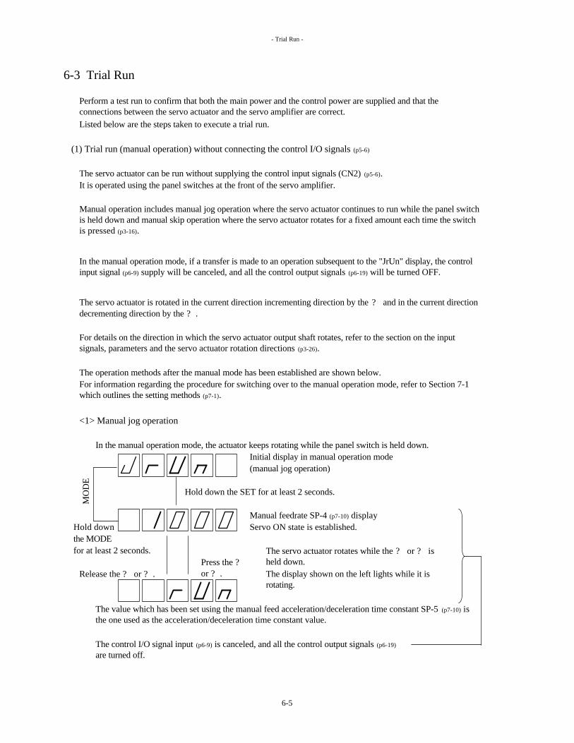
- Trial Run -
6-3 Trial Run
Listed below are the steps taken to execute a trial run.
(1) Trial run (manual operation) without connecting the control I/O signals (p5-6)
The servo actuator can be run without supplying the control input signals (CN2) (p5-6).It is operated using the panel switches at the front of the servo amplifier.
The operation methods after the manual mode has been established are shown below.
<1> Manual jog operation
In the manual operation mode, the actuator keeps rotating while the panel switch is held down.Initial display in manual operation mode(manual jog operation)
Hold down the SET for at least 2 seconds.
Manual feedrate SP-4 (p7-10) display Hold down Servo ON state is established. the MODE for at least 2 seconds.
Release the ? or ? .
The value which has been set using the manual feed acceleration/deceleration time constant SP-5 (p7-10) is the one used as the acceleration/deceleration time constant value.
In the manual operation mode, if a transfer is made to an operation subsequent to the "JrUn" display, the control input signal (p6-9) supply will be canceled, and all the control output signals (p6-19) will be turned OFF.
The control I/O signal input (p6-9) is canceled, and all the control output signals (p6-19)
are turned off.
For information regarding the procedure for switching over to the manual operation mode, refer to Section 7-1 which outlines the setting methods (p7-1).
MO
DE
Press the ?or ? .
The servo actuator rotates while the ? or ? is held down.The display shown on the left lights while it is rotating.
Perform a test run to confirm that both the main power and the control power are supplied and that the connections between the servo actuator and the servo amplifier are correct.
Manual operation includes manual jog operation where the servo actuator continues to run while the panel switch is held down and manual skip operation where the servo actuator rotates for a fixed amount each time the switch is pressed (p3-16).
The servo actuator is rotated in the current direction incrementing direction by the ? and in the current direction decrementing direction by the ? .
For details on the direction in which the servo actuator output shaft rotates, refer to the section on the input signals, parameters and the servo actuator rotation directions (p3-26).
6-5

- Trial Run -
<2> Manual skip operation
Manual operation mode initial display(manual jog operation)
DOWN ? ? UP
Manual skip operation mode display
Hold down the SET for 2 or more seconds.
Skip amount SP-6 (p7-10)
Hold down the MODE for at least 2 seconds.
Release the ? or ? . Press the ? or ? .
There is no need to hold down the ? and ? .The servo actuator rotates by the skip amount when the ON edge of the ? or ? is detected.
(2) Trial run using control I/O signals (p3-12)
Operations (I/O jog operations) can be performed using the FWD and RVS (p6-15) input signals.
The servo actuator will not rotate if these signals are OFF.
MO
DE
Every time the panel switch is pressed, the servo actuator rotates by an amount equivalent to the skip amount SP-6 (p7-10) value.
The servo actuator is rotated by the skip amount in the current position incrementing direction by pressing the ? and in the decrementing direction by pressing the ? .
Shown as the skip amount units are the encoder pulses after they have been multiplied 4 times. The servo ON status is established.
When the + over-travel, - over-travel (p6-13) and external failure input (p6-12) signals have been allocated to CONT1 to 14 (p6-10), set each of the signals to ON.
For further details, refer to <7> I/O jog operation (p3-12) in Section 3-2 on the basic command methods.
(The display shown on the left lights while the servo actuator is rotating.)
For details on the direction in which the servo actuator output shaft rotates, refer to the section on the input signals, parameters and servo actuator rotation directions (p3-26).
The value which has been set by manual feedrate SP-4 (p7-10) serves as the rotation speed of the motor.
The value which has been set using the manual feed acceleration/deceleration time constant SP-5 (p7-10) is the one used as the acceleration/deceleration time constant value.
6-6

- Origin Setting -
6-4 Origin Setting
(1) With the absolute encoder
Use the panel switches at the front of the servo amplifier to set the origin as described below.
<1> Operate the servo actuator, and locate the machine origin.
<2>
When the origin is set, the following operations are performed inside the system.The multi-rotation counter of the absolute encoder is reset.
Origin settings are available in any main operation mode (p3-5).
Once the manual operation mode has been established, operate as indicated below.
Manual operation mode initial display(manual jog operation mode (p3-16))
DOWN ? ? UP
Manual skip operation mode display (p3-16)
DOWN ? ? UP
Origin setting mode display
MODE Hold down the SET for 2 seconds.
A dot appears here if the value is a negative one.
Press the ? and ? together for 2 seconds.
The origin is now set.(The display flashes.)
When locating the machine origin, the servo actuator can be driven by I/O jog operation (p3-12), manual jog operation (p3-16) or manual skip operation (3-16).
Origin return position setting : CP-22 (p7-19) value displayed here
Aut
omat
ic re
turn
When the machine origin has been located, follow the steps below to set the coordinate origin of the absolute encoder.
The current position on the coordinate axes is changed to the origin return position setting CP-22 (p7-19).
In the case of equal pitch multi-rotation coordinates (p3-6) (coordinate axis: CP-8=1 (p7-15)), the positions of all the positioning addresses are shifted by an amount equivalent to the origin return position setting (p7-19).
Press the mode switch on the front panel of the servo amplifier to establish the manual operation mode. (p7-1)
6-7

- Origin Setting -
(2) With the incremental encoder
When the incremental encoder is used, set the origin by conducting the origin return operation that employs the LS signal. Refer to p6-14, 3-14 for details.
(Origin return can also be conducted using the panel switches at the front of servo amplifier as with the absolute encoder.)
6-8
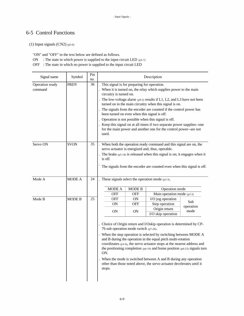
- Input Signals -
6-5 Control Functions
(1) Input signals (CN2) (p5-6)
"ON" and "OFF" in the text below are defined as follows.ON : The state in which power is supplied to the input circuit LED (p5-7)
OFF : The state in which no power is supplied to the input circuit LED
Operation ready PRDY This signal is for preparing for operation.command
Operation is not possible when this signal is off.
Servo ON SVON
Mode A MODE A These signals select the operation mode (p3-3).
Mode B MODE B
When both the operation ready command and this signal are on, the servo actuator is energized and, thus, operable.The brake (p5-14) is released when this signal is on; it engages when it is off.
The signals from the encoder are counted even when this signal is off.
Main operation mode (p3-3)
Operation mode
Step operationI/O jog operation
I/O skip operation
Sub operation
modeOrigin return
Symbol Pin no.
OFF ON25OFF
When it is turned on, the relay which supplies power to the main circuitry is turned on.The low-voltage alarm (p9-2) results if L1, L2, and L3 have not been turned on in the main circuitry when this signal is on.The signals from the encoder are counted if the control power has been turned on even when this signal is off.
Keep this signal on at all times if two separate power supplies--one for the main power and another one for the control power--are not used.
ON OFF
OFF
Signal name
MODE A MODE B
Description
36
35
24
ON ON
When the step operation is selected by switching between MODE A and B during the operation in the equal pitch multi-rotation coordinates (p3-6), the servo actuator stops at the nearest address and the positioning completion (p6-19) and home position (p6-23) signals turn ON.
When the mode is switched between A and B during any operation other than those noted above, the servo actuator decelerates until it stops.
Choice of Origin return and I/Oskip operation is determined by CP-76 sub operation mode switch (p7-26).
6-9
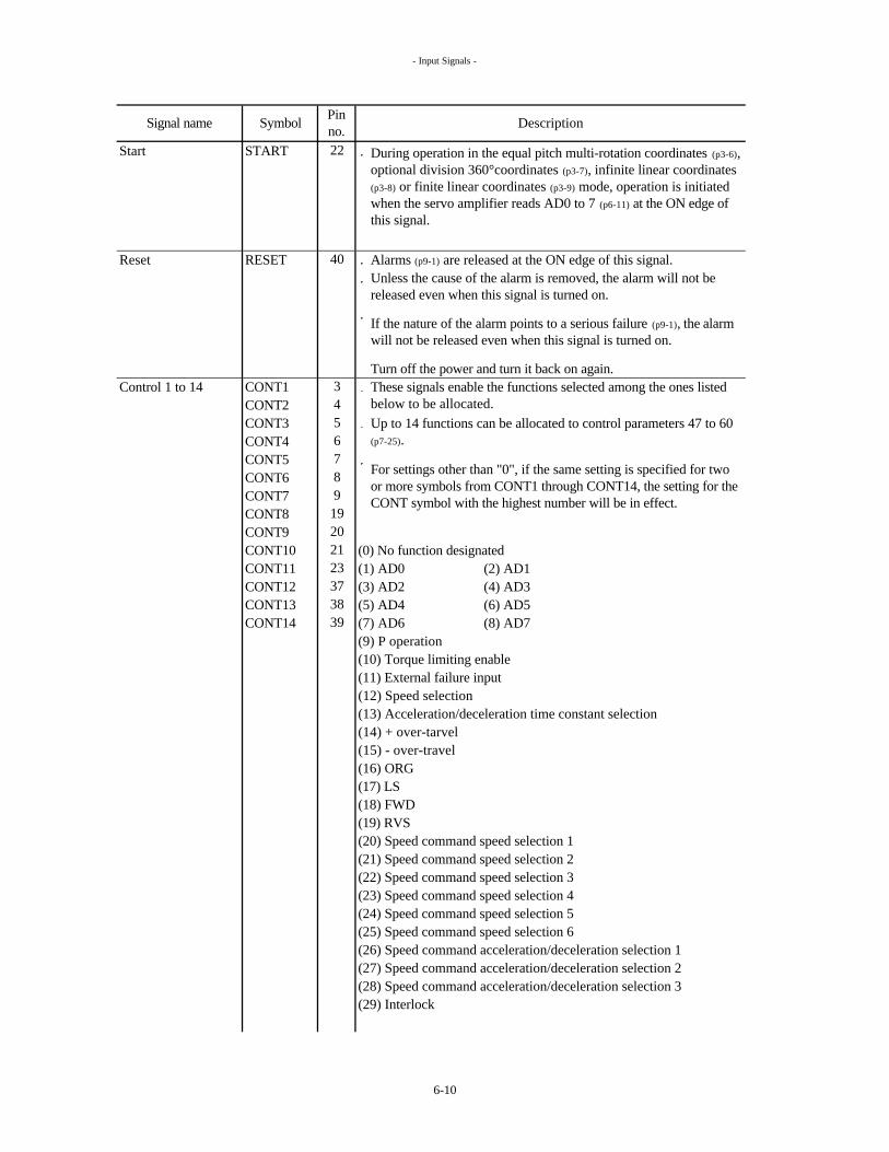
- Input Signals -
Start START
Reset RESET Alarms (p9-1) are released at the ON edge of this signal.
Turn off the power and turn it back on again.Control 1 to 14 CONT1
CONT2CONT3CONT4CONT5CONT6CONT7CONT8CONT9CONT10 (0) No function designatedCONT11 (1) AD0 (2) AD1CONT12 (3) AD2 (4) AD3CONT13 (5) AD4 (6) AD5CONT14 (7) AD6 (8) AD7
(9) P operation(10) Torque limiting enable(11) External failure input(12) Speed selection(13) Acceleration/deceleration time constant selection(14) + over-tarvel(15) - over-travel(16) ORG(17) LS(18) FWD(19) RVS(20) Speed command speed selection 1(21) Speed command speed selection 2(22) Speed command speed selection 3(23) Speed command speed selection 4(24) Speed command speed selection 5(25) Speed command speed selection 6(26) Speed command acceleration/deceleration selection 1(27) Speed command acceleration/deceleration selection 2(28) Speed command acceleration/deceleration selection 3(29) Interlock
Description
6
These signals enable the functions selected among the ones listed below to be allocated.
19
During operation in the equal pitch multi-rotation coordinates (p3-6), optional division 360°coordinates (p3-7), infinite linear coordinates (p3-8) or finite linear coordinates (p3-9) mode, operation is initiated when the servo amplifier reads AD0 to 7 (p6-11) at the ON edge of this signal.
Unless the cause of the alarm is removed, the alarm will not be released even when this signal is turned on.
Up to 14 functions can be allocated to control parameters 47 to 60 (p7-25).
For settings other than "0", if the same setting is specified for two or more symbols from CONT1 through CONT14, the setting for the CONT symbol with the highest number will be in effect.
If the nature of the alarm points to a serious failure (p9-1), the alarm will not be released even when this signal is turned on.
7
Signal name
34
Symbol Pin no.
40
22
5
89
38
20212337
39
6-10

- Input Signals -
Control 1 to 14 (1) AD0 to (8) AD7 (address numbers)
Example: When AD1, 3 and 5 are on, the address is 42 (2+8+32).Example:
Positioning completion width: CP-24 (p7-19)
Rotation speed
Current addressServo ON (p6-9)
AD0
*1 *1
Start (p6-10)
(p6-19)
*1
*2
These signals are each read at the start signal (p6-10) rise, and the servo actuator starts rotating in the direction of the addresses of the signal concerned.They take effect in the equal pitch multi-rotation coordinates (p3-6), optional division 360° coordinates (p3-7), infinite linear coordinates (p3-8) and finite linear coordinates (p3-9) modes.
These signals are each recognized by a binary number. Shown below is the correspondence with decimal numbers.
When the maximum number of addresses is 7, there is no need to allocate functions to AD3 to 7.
1622
128 64 322527 26 24
AD7 AD6 AD0AD1AD5 AD4 AD3 AD223
22021
ON
OFF
ON
After the start signal has been set on (started), the positioning contents will remain unchanged even if the address numbers (input values of AD0 to 7) are changed.
AD1
Rotation is started at the ON edge of the start signal. Operation to the next address is not executed if the signal is permanently on.
Positioning completion (P61)
OFF
*2
ON
Signal name
1
Description
2
Symbol Pin no.
18 4
6-11

- Input Signals -
Control 1 to 14 (9) P operation
The signal enables the servo rigidity to be weakened.
(10) Torque limiting enable
This function limits the output torque of the servo actuator.The output torque is limited when this signal is on.The limit level is set by the torque limit value CP-34 (p7-20).
[%](Rated torque = 100%)
(11) External failure input
(12) Speed selection
Motor acceleration/deceleration time constants
SP-10: Acceleration/deceleration time constant 2
SP-9: Acceleration/deceleration time constant 1
ON
OFF
Input status of speed selection Motor rotation speed
SP-8: Speed 2 for equal division
SP-7: Speed 1 for equal division
Selected servo parameter
When the servo ON signal (p6-9) is on, the holding torque remains in force even after shutdown.Even if this signal is reset, the operation cannot resume unless a signal to direct the operation, such as START (p6-10), FWD (p6-15), etc., is input.The rotation commands (including the pulse train commands) which have been input while this signal is off are invalid.
350
AR10H
This is used to stop the servo actuator when a failure has occurred in an external device.The servo actuator stops immediately when this signal is turned off, while maintaining its power.
AR135
300350
AR15ARH7 ARH17
Signal name DescriptionPin no.Symbol
When this signal is set on, the speed loop control goes from proportional and integral control to proportional control only.
This selects the motor rotation speed and the motor acceleration/deceleration time constant in the equal pitch multi-rotation coordinates (p3-6) mode.The servo amplifier reads the input status at the ON edge of the start signal (p6-10).The relation between the ON/OFF statuses and the selected servo parameters is as below.
The maximum torque (= maximum torque limit value) when the torque is not limited is as below.
ARH24350
AR30 AR60
350
6-12
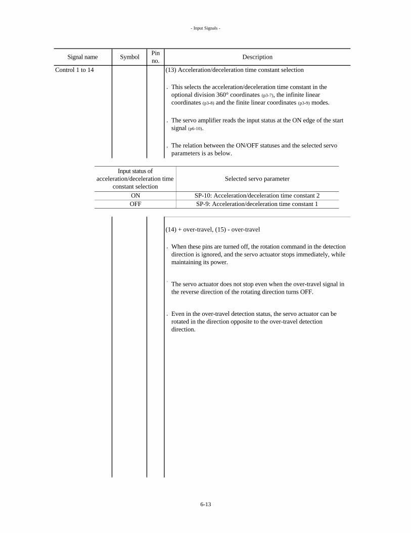
- Input Signals -
Control 1 to 14 (13) Acceleration/deceleration time constant selection
(14) + over-travel, (15) - over-travel
ONOFF
Selected servo parameter
The servo amplifier reads the input status at the ON edge of the start signal (p6-10).
The relation between the ON/OFF statuses and the selected servo parameters is as below.
Input status of acceleration/deceleration time
constant selection
When these pins are turned off, the rotation command in the detection direction is ignored, and the servo actuator stops immediately, while maintaining its power.
Even in the over-travel detection status, the servo actuator can be rotated in the direction opposite to the over-travel detection direction.
Signal name DescriptionPin no.Symbol
SP-10: Acceleration/deceleration time constant 2
The servo actuator does not stop even when the over-travel signal in the reverse direction of the rotating direction turns OFF.
This selects the acceleration/deceleration time constant in the optional division 360° coordinates (p3-7), the infinite linear coordinates (p3-8) and the finite linear coordinates (p3-9) modes.
SP-9: Acceleration/deceleration time constant 1
6-13

- Input Signals -
Control 1 to 14 (16) ORG
(17) LSThis is for the origin return limit switch input.
Origin return timing chartOrigin return speed : CP-19 (p7-19)
Rotation speed Origin return creep speed: CP-20 (p7-19)
Origin return shift amountORG : CP-21 (p7-19)
LS
Encoder Z phase (Z-OUT) (p5-9)
Origin return completion (p6-22)
(Invalid if the origin return is executed in the equal pitch multi-rotation coordinates (p3-6).)
<1>
<2>
<3>
(The Z phase signal is output once for each complete rotation of the motor.)
<4>
The origin return completion signal is turned on.
When either the + over-travel or the - over-travel signal (p6-13) in the rotating direction is detected during the origin return operation, the servo actuator stops immediately. In this case, step <4> above is not executed.
Starting at the moment when the origin LS signal goes from off to on, the servo actuator decelerates at the origin return creep speed (CP-20 setting, p7-19). In this case, the acceleration/deceleration time constant 1 SP-9 setting serves as the acceleration/deceleration time constant.
OFF
OFF
After origin return has been set, the origin return completion signal turns on if the current position of the servo actuator is within the origin detection range CP-23 (p7-19) setting centered on the origin.
In the case of equal pitch multi-rotation coordinates (coordinate axes: CP-8=1, p7-15), the positioning addresses positions are shifted by an amount equivalent to the origin return position setting.
The origin return operation is started at the ON edge of this signal.
When the ORG signal changes to ON from OFF in the timing chart, then the servo actuator is operated at the origin return speed (CP-19 setting, p7-19) in the origin return direction (CP-18 setting, p7-19).
When the first encoder Z phase signal is detected after the origin LS signal goes from on to off, the servo actuator stops at the position reached after having rotated for the equivalent of the origin return shift amount CP-21 (p7-19) setting (unit: encoder pulses).
The current position of the coordinate axes is changed to the origin return position CP-22 (p7-19) setting (unit = encoder pulses).
ON
Acceleration/deceleration
time constant 1: SP-9 (p7-11)
OFF
Positioning completion (p6-19)
SymbolSignal name Pin no. Description
6-14

- Input Signals -
Control 1 to 14 (18) FWD (forward) (19) RVS (reverse)
FWD:
RVS:
The rotation speed is set as follows.
In the speed command operation mode (p3-11):
The acceleration/deceleration time constant is set as follows.
In the speed command operation mode (p3-11):
Timing chart during I/O jog operations (p3-12)
FWD
RVSServo actuator stops when both the FWD and RVS signals are on.
Rotation speed Manual feedrate 1: SP-4
When FWD is thenManual feed acceleration/deceleration time constant: SP-5 (p7-10) turned off, RVS takes effect.
The servo actuator rotates in the current position incrementing direction while this signal is on.The servo actuator rotates in the current position decrementing direction while this signal is on.
These signals take effect with I/O jog operation, step operation and speed command.
Signal name Symbol Pin no. Description
For the rotation direction of the servo actuator, refer to input signals, parameters and rotation directions of the servo actuator (p3-26).
The manual feedrate (SP-4, p7-10) setting is applied to operations.
The speed can be selected from speed command speed 1 to 6 (SP-11 to SP-16) (p7-11) by the speed command speed selection 1 to 6 (p6-16).
I/O jog operation (p3-12)
Step operation (p3-13)
I/O skip operation (p3-15)
Speed command operation (p3-11)
The speed command speed 1 is automatically selected if speed command speed selections 1 to 6 have not been allocated to control 1 to 14 or if all the signals are off even when these selections have been allocated.
I/O jog operation (p3-12)The manual feed acceleration/deceleration time constant (SP-5, p7-10) setting is applied to these operations.Step operation (p3-13)
I/O skip operation (p3-15)
OFF
OFF
The time constant can be selected from speed command acceleration/deceleration 1, 2 or 3 (SP-17, SP-18 or SP-19) (p7-12) by the speed command acceleration/deceleration selection 1, 2 or 3 (p6-17).
Speed command operation (p3-11)
The speed command acceleration/deceleration 1 is automatically selected if speed command acceleration/deceleration selections 1 to 3 have not been allocated to control 1 to 14 or if all the signals are off even when these selections have been allocated.
6-15

- Input Signals -
Control 1 to 14 (20) Speed command speed selection 1(21) Speed command speed selection 2(22) Speed command speed selection 3(23) Speed command speed selection 4(24) Speed command speed selection 5(25) Speed command speed selection 6
The motor rotates at the speed which has been set in speed command speed 1 to 6 (SP-11 to SP-16) (p7-11) by issuing the rotation command (turning on the FWD or RVS signal) after this signal is input.
The rotation direction is determined by the FWD or RVS signal.
Signal name Symbol Pin no. Description
During the FWD or RVS signal ON period, when the ON edges of two or more signals have been detected in 2ms or so, the servo actuator decelerates until it stops.
This signal has first-in priority during the FWD or RVS signal ON period.
When the command has been changed during acceleration or deceleration, the speed changes to the post-change speed after the pre-change speed has been reached.
For the rotation direction of the servo actuator, refer to input signals, parameters and rotation directions of the servo actuator (p3-26).
6-16

- Input Signals -
Control 1 to 14 (26) Speed command acceleration/deceleration selection 1(27) Speed command acceleration/deceleration selection 2(28) Speed command acceleration/deceleration selection 3
Ignored ON ignoredEffective during deceleration
FWD (p6-15)
RVS (p6-15)
First-in
Ignored Effective
Speed command speed 2: SP-12 (p7-11)
*
Speed command acceleration/decelerationselection 1: SP-17 (p6-17)
Speed command acceleration/deceleration selection 2: SP-18
Speed command speed 1: SP-11 (p7-11)
When the command has been changed during acceleration or deceleration, the command is not reflected immediately but starting when the next acceleration/deceleration command has been generated.
Description
This signal selects the acceleration/deceleration time constant to be used when the speed command is issued.
This signal has first-in priority during the FWD or RVS (p6-15) signal ON period.
Upon issuance of a speed change command (* in the following diagram), when two or more signals are ON, the servo actuator decelerates until it stops.
OFF
Rotation speed
Signal name Symbol Pin no.
Speed command acceleration/deceleration selection 1 (p6-17)
Speed command acceleration/deceleration selection 2 (p6-17)
Speed command speed selection 1 (p6-16)
First-in
OFFSpeed command speed selection 2 (p6-16)
OFF
OFF
ON
OFF
No rotation when FWD or RVS has been turned on while two or more selection signals have been input.
6-17

- Input Signals -
Control 1 to 14 (29) Interlock
Rotation is prohibited while this signal is on.
This logic can be reversed using this parameter.
Example of equal pitch multi-rotation coordinates (p3-6): CP-8=1
8 1 0
6 7 8 9 1 0
Description
Operation underway (p6-21)
MODE A (p6-9)
Interlock
Command address
AD0 (p6-11)
AD1
AD2
Signal name
OUT-AD1
Symbol Pin no.
ON
AD3
OUT-AD0 (p6-20)
ON
Start (p6-10)
Current address
When this signal turns on, the servo actuator decelerates until it stops.
OFF
OFF
The servo lock status is established while the servo actuator has stopped.
The above logic and chart below apply when interlock logic CP-43 (p7-22) is 1 (default value).
The remaining operations are executed when this signal turns off.
In this case, the interlock signal is input around address 9 during operation from address 8 toward address 10, the servo actuator stops, the interlock is then released, and the servo actuator is positioned at address 10.
Positioning completion (p6-19)
OFF
Home position (p6-23)
OFF
OUT-AD2
OUT-AD3
ON
ON
ON
Rotation speed
MODE B (p6-9) OFF
ON
OFF
OFF
ON
6-18

- Output signals -
(2) Output signals (CN2) (p5-6)
"ON" and "OFF" in the text below are defined as follows.
ON : The state in which the output circuit transistors (p5-7) are ONOFF : The state in which the output circuit transistors are OFF.
Positioning INP This signal turns ON under the following conditions.completion
Out 1 to 15 OUT1OUT2OUT3OUT4OUT5 The same function can be set in more than one pin.OUT6OUT7 (0) No function designatedOUT8 (1) OUT-AD0OUT9 (2) OUT-AD1OUT10 (3) OUT-AD2OUT11 (4) OUT-AD3OUT12 (5) OUT-AD4OUT13 (6) OUT-AD5OUT14 (7) OUT-AD6OUT15 (8) OUT-AD7
(9) Operation ready completion(10) Servo ON/OUT(11) Operation underway(12) Fixed point/through point 1(13) Fixed point/through point 2(14) Over-travel detection(15) Origin return completion(16) Alarm detection(17) Speed arrival(18) Home position(19) Torque limiting underway(20) Positioning completion
Description
434432
11
16
12131415
Signal name SymbolPin no.31
4142
27282930
For the optional division 360° coordinates, the infinite linear coordinates, the finite linear coordinates and the pulse train operation : | Command position – Current position | < Positioning completion width (CP-24, p7-19)
These signals enable the functions selected from among the ones listed below to be allocated.Up to 15 functions can be allocated to control parameters 61 to 75 (p7-26).
For equal pitch multi-rotation coordinates (p3-6) : In the main operation mode (p3-5) or the step operation mode (p3-13), | Target address position – Current position | < Positioning completion width (CP-24, p7-19)
6-19

- Output signals -
Out 1 to 15 (1) OUT-AD0 to (8) OUT-AD7
These signals output the current address.
(9) Operation ready completion
Conditions When operation ready command (p6-9) is ONWhen no alarms (p9-1) have occurred
(10) Servo ON/OUT
Conditions When operation ready command (p6-9) is ONWhen no alarms (p9-1) have occurredWhen servo ON (p6-9) is ONWhen the power save timer (p7-21) is not active (the brake is not applied)
This signal turns on when both of the following conditions have been met.
After the operation ready command has turned on, there is a delay of approximately (300ms=ARN15,30 : 600ms=ARN60,135) before this signal is output.
After the operation ready command has turned on, there is a delay of of approximately (300ms=ARN15,30 : 600ms=ARN60,135) before this signal is output.
Optional division 360° coordinates (p3-7)
Infinite linear coordinates (p3-8)
Finite linear coordinates (p3-9) 4
23
This signal turns on when all of the following conditions have been met.
This signal indicates the power is being supplied to the servo motor.
Target address
Coordinate axes: CP-8 (p7-15)
These signals take effect, in the case of an absolute encoder, after the power is turned on, since the previous position has been backed up even when the power is OFF.However, in the case of an incremental encoder, this signal is output in accordance with the "zero" position that will be recognized when the power is turned ON.
Equal pitch multi-rotation coordinates (p3-6) Address nearest the current position
The correlation between the coordinate axes and output logic is as shown below.
1Output logic
The same binary number output format as for AD0 to 7 (p6-11) of control 1 to 14 is used.
Signal name Symbol Pin no. Description
6-20
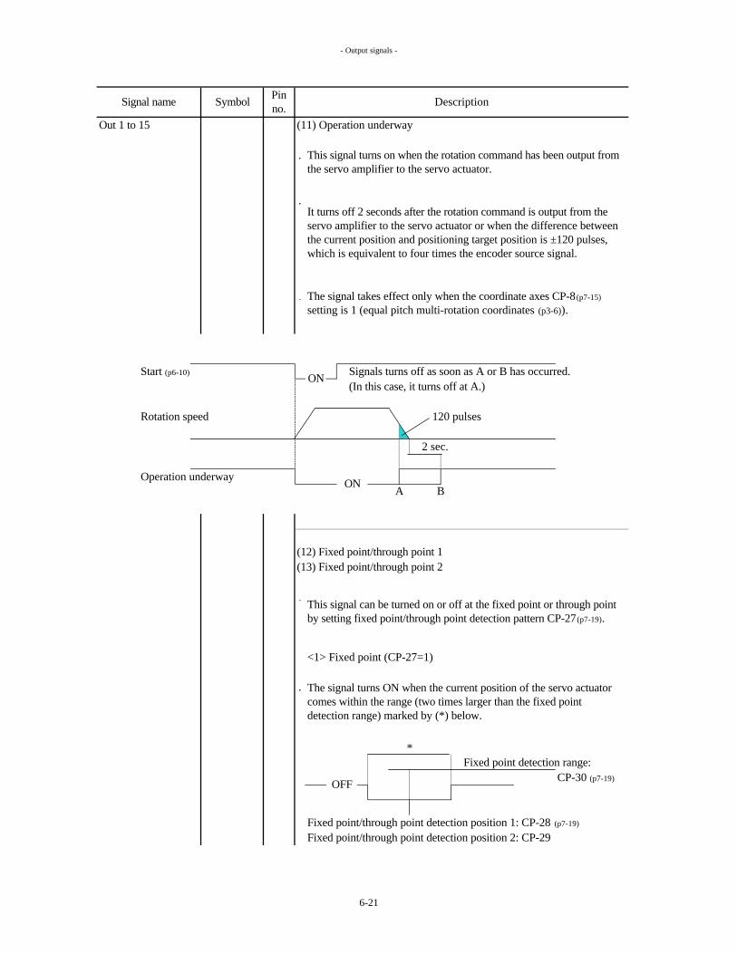
- Output signals -
Out 1 to 15 (11) Operation underway
Start (p6-10) Signals turns off as soon as A or B has occurred.(In this case, it turns off at A.)
Rotation speed 120 pulses
2 sec.
Operation underway
(12) Fixed point/through point 1(13) Fixed point/through point 2
<1> Fixed point (CP-27=1)
Fixed point detection range:CP-30 (p7-19)
Fixed point/through point detection position 1: CP-28 (p7-19)
Fixed point/through point detection position 2: CP-29
This signal turns on when the rotation command has been output from the servo amplifier to the servo actuator.
It turns off 2 seconds after the rotation command is output from the servo amplifier to the servo actuator or when the difference between the current position and positioning target position is ±120 pulses, which is equivalent to four times the encoder source signal.
This signal can be turned on or off at the fixed point or through point by setting fixed point/through point detection pattern CP-27 (p7-19).
ON
The signal takes effect only when the coordinate axes CP-8 (p7-15)
setting is 1 (equal pitch multi-rotation coordinates (p3-6)).
The signal turns ON when the current position of the servo actuator comes within the range (two times larger than the fixed point detection range) marked by (*) below.
OFF
Signal name Symbol Pin no. Description
*
ON
A B
6-21

- Output signals -
Out 1 to 15 <2> Through point (CP-27=2)
Fixed point/through point detection position 1: CP-28 (p7-19)
Fixed point/through point detection position 2: CP-29
(14) Over-travel detection
Conditions + over-travel signal (p6-13) has gone off.- over-travel signal (p6-13) has gone off.
(15) Origin return completion
This signal turns on upon completion of origin return.
Origin detection range: CP-23 (p7-19)
Origin return position setting: CP-22 (p7-19)
OFF
The signal turns on when the current position of the servo actuator is more than the through point setting position; it turns off if it is less.
This signal turns on when one of the following conditions has occurred.
Current position is more than soft + over-travel detection position CP-31 (p7-20).Current position is less than soft - over-travel detection position CP-32 (p7-20).
Current positionincrementing direction
*
When a value except zero is input for the CP-22 origin return position setting (p7-19), the origin return completion signal may not turn ON at the position where origin return was executed because the coordinate origin position differs from the position where origin return was executed.
Subsequently, it turns on when the current position of the servo actuator comes within the range marked with an asterisk (*) shown below (twice of the origin detection range). (See page 3-14)
Concerning the equal pitch multi-rotation coordinates (p3-6) and the optional division 360° coordinates (p3-7), the coordinate axis shifts automatically during operation. Therefore, this signal does not necessarily correspond to the mechanical origin point.
OFF
Signal name Symbol Pin no. Description
6-22

- Output signals -
Out 1 to 15 (16) Alarm detection
This signal turns on when an alarm (p9-1) is detected.
(17) Speed arrival
Rotation speed
Speed arrival
(18) Home position
Home position detection range CP-36 (p7-21)
Position of addresses
To release the alarm status, remove the cause of the alarm and either turn on the reset signal (p6-10) or turn off the main power and control power and then turn them back on again.
The external failure input (p6-12), + over-travel and - over-travel (p6-
13) and interlock (p6-18) are not identified as an alarm status.
This signal turns on when the motor rotation speed exceeds the speed arrival identification speed CP-26 (p7-19) setting.
This signal turns on when the current position of the servo actuator has come within the range, marked with an asterisk (*), of each address shown below (This range is twice that of the home position detection range).
ON
Speed arrival identification speed CP-26
OFF
*
The home position detection width is set using home position detection range CP-36 (p7-21).
The signal takes effect only when the coordinate axes CP-8 (p7-15)
setting is 1 (equal pitch multi-rotation coordinates (p3-6)).
Signal name Symbol Pin no. Description
6-23

- Output signals -
Out 1 to 15 (19) Torque limiting underway
This signal turns on when the following conditions is met.
Conditions
(20) Positioning completion
Battery alarm BAT ALM
Signal name Symbol Pin no. Description
It has the same function as the battery voltage drop warning LED (red) (p5-1,3) on the front panel.
When this signal has turned on, replace the battery immediately. (See page 5-19)
46
The torque limiting enable signal (p6-12) of control 1 to 14 is turned on, and the motor torque has been limited by the torque limit value CP-34 setting.
The function of this signal is the same as that of INP (positioning completion) noted on page 6-19.
The same function as the positioning completion can be allocated to OUT1 through OUT15.
This signal turns on when the voltage of the battery (p5-19) for the absolute encoder has dropped.
6-24

- Overview of Setting Methods -
7-1 Overview of Setting MethodsH E L L O
A r n 1 5 , 3 0 , 6 0 , 1 3 5
A b S , I n C ,Press MODE for 2 sec.
1. S P E d : Motor rotation speed S P - 1 : Speed loop proportional gain p7-9
2. P A d d : Position address number 2 : Speed loop integral gain p7-9
? 3. P O S : Current position ? ? ? 3 : Position loop gain p7-9
4. r P O S : Requested position ? ? 4 : Manual feedrate p7-10
5. P t O r : Percentage torque 5 : p7-10
? 6. d P U L : Deviation pulse ? ? ? 6 : Skip amount p7-10
7. F P U L : Feedback pulse ? ? 7 : Speed 1 for equal division p7-10
8. r P U L : Requested pulse ? ? 8 : Speed 2 for equal division p7-10
9. A L H I : Alarm history 9 : Acceleration/deceleration time constant 1 p7-11
1 0. d I : Digital input monitor 1 0 : Acceleration/deceleration time constant 2 p7-11
1 1. d O : Digital output monitor 1 1 : Speed command speed 1 p7-11
1 2. v E r : Software version 1 2 : Speed command speed 2 p7-11
1 3 : Speed command speed 3 p7-11
? : There are five or more upper digits. 1 4 : Speed command speed 4 p7-11
? : Positive or negative value. 1 5 : Speed command speed 5 p7-11
1 6 : Speed command speed 6 p7-11
1 7 : Speed command acceleration/deceleration 1 p7-12
1 8 : Speed command acceleration/deceleration 2 p7-12
S P - 1 9 : Speed command acceleration/deceleration 3 p7-12
Press MODE for 2 sec.
Display mode (p7-3) Servo parameters (SP) (p7-9)
Manual feed acceleration/deceleration time constant
7. SETTING METHODS
Press MODE for 2 sec.
Frame no. display
Encoder display (p6-3)
Power ON (p6-3)
10H
7-1

- Overview of Setting Methods -
C P - 1 J r U n : Manual jog (p6-5) n 1 : Address #1
C P - 2 ? S r U n : Manual skip (p6-6) ? n 2 : Address #2
O r I G : Origin setting (p6-7)
C P - 7 5 ? ? n 2 5 5 : Address #255
1 Encoder type 40 Power save timer time 76 Sub operation mode switch2 Reduction gear ratio numerator 41 Overshoot amount 77 Factory use (Not for user)3 Reduction gear ratio denominator 42 Number of follow-up pulses 784 Electronic gear a? 43 Interlock logic5 Electronic gear ß? 44 Rewriting prohibited 79 Position defect alarm width6 Unit amount 45 Monitor selection7 Brake available/unavailable 46 Display contents when power is turned on8 Coordinate axis 47 Control 19 Number of divisions 48 Control 210 Total number of addresses 49 Control 311 Optional division short-cut control 50 Control 4 (0) No function designated12 Indexing number incrementing direction 51 Control 5 (1) AD0 (0) No function designated13 MF/FIN available/unavailable 52 Control 6 (2) AD1 (1) OUT-AD014 Short-cut/unidirectional selection 53 Control 7 (3) AD2 (2) OUT-AD115 2-position indexing direction selection 54 Control 8 (4) AD3 (3) OUT-AD216 Input pulse system 55 Control 9 (5) AD4 (4) OUT-AD317 Pulse train operation rotation direction 56 Control 10 (6) AD5 (5) OUT-AD418 Origin return direction 57 Control 11 (7) AD6 (6) OUT-AD519 Origin return speed 58 Control 12 (8) AD7 (7) OUT-AD620 Origin return creep speed 59 Control 13 (9) P operation (8) OUT-AD721 Origin return shift amount 60 Control 14 (10) Torque limiting enable (9) Operation ready completion22 Origin return position setting 61 Out 1 (11) External failure input (10) Servo ON/OUT23 Origin detection range 62 Out 2 (12) Speed selection (11) Operation underway24 Positioning completion width 63 Out 3 (13) Acceleration/deceleration time (12) Fixed point/through point 125 Excessive deviation width 64 Out 4 (13) Fixed point/through point 226 Speed arrival identification speed 65 Out 5 (14) Over-travel detection27 66 Out 6 (14) + over-travel (15) Origin return completion
67 Out 7 (15) - over-tarvel (16) Alarm detection28 68 Out 8 (16) ORG (17) Speed arrival
69 Out 9 (17) LS (18) Home position29 70 Out 10 (18) FWD (19) Torque limiting underway
71 Out 11 (19) RVS (20) Positioning completion30 Fixed point detection range 72 Out 12 (20) Speed command speed selection 131 Soft + over-travel detection position? ? 73 Out 13 (21) Speed command speed selection 232 Soft - over-travel detection position? ? 74 Out 14 (22) Speed command speed selection 333 Speed limit value 75 Out 15 (23) Speed command speed selection 434 Torque limit value (24) Speed command speed selection 535 Brake forcible release (25) Speed command speed selection 636 Home position detection range (26) Speed command acceleration/deceleration selection 137 Backlash compensation amount (27) Speed command acceleration/deceleration selection 238 Backlash compensation direction (28) Speed command acceleration/deceleration selection 339 Power save timer available/unavailable (29) Interlock
? : There are five or more upper digits. ? : Positive or negative value.
Position defect alarm available/unavailable
Manual operation mode
Press MODE for 2 sec.
Press MODE for 2 sec. Press MODE for 2 sec.
Control parameters (CP) (p7-13) Positioning data editing mode (p7-33)
Alarm display (p9-1) (only upon alarm occurrence)Press MODE for 2 sec.
Fixed point/through point detection position 2? ?
Functions allocated to control 1 to 14 (p6-10) Functions allocated to out 1 to 15 (p6-
19)
Acceleration / deceleration time constant selection
Fixed point/through point detection pattern
Fixed point/through point detection position 1? ?
7-2

- Detailed Description of Display Modes -
7-2 Detailed Description of Display Modes
When the power is turned on, the frame number and the encoder are displayed, respectively. (p6-3)
? Items marked with a black dot have high-order digits when their contents are displayed (p7-6).
Motor Displays the rotation speed of the motor.rotationspeed [rpm]Position Displays the requested address AD0 to 7 (p6-11).addressnumber [Position address number]Current Displays the current position.
? Position For details, refer to the table on p7-4.[Position address number or unit amount]
Requested Displays the requested address position data.? position For details, refer to the table on p7-4.
[Unit amount]Percentage Displays the torque command value.torque The rated torque is 100%.
[%]Deviationpulse
? For details, refer to the table on p7-4.[Encoder pulse]
Feedbackpulse
? • For details, refer to the table on p7-4.[Encoder pulse]
Requested This is the internal request value.pulse
?
[Encoder pulse]Alarmhistory
Displays the number calculated from “(Cumulative total number of pulses which have been input from the external source [Number of ?and ? for CP-16, p7-18]) x Electronic gear a /Electronic gear ß ” during the pulse train operation (p3-10).
Among the alarms which have occurred in the past (p9-1), this displays the alarm which occurred last.A history of the last 10 alarms is displayed by pressing the button on the front panel.The alarms are displayed in sequence starting with the most recent one.
Then, the display mode is indicated. You can select the mode item to be displayed using the ? and ? . (p7-1)
Which item of the display mode is to be displayed when the power is turned on can be selected using the "display contents when power is turned on" CP-46 (p7-24) setting. This parameter's default is the motor rotation speed.
Displays the cumulative number of pulses which have been fed back from the encoder.
Displays the difference between the requested pulse and feedback pulse.
Remarks
5
6
7
1No. Item Display
9
8
2
3
4
7-3

- Detailed Description of Display Modes -
The method used to display the alarm history is described below.
MODE
SET
This number displays the most recent alarm.DOWN ? Alarm 5 = overcurrent.
This is the second most recent alarm.
UP ?Alarm 11 = Encoder trouble.
The encoder pulses are the A- and B-phase signals multiplied by 4.
-
-Start (p6-10)
ON position
Origin
Unit
When the START signal (p6-10) turns on, both the current and requested positions of the infinite linear coordinates are reset to zero.
What is displayed in the sub operation modes is the same as what is selected as the main operation mode.
Displayed as the current position of the equal pitch multi-rotation coordinates is the address closest to the current position.When the reset signal (p6-10) is turned on and the alarm is released, the requested pulse will have the same value as the feedback pulse.
When an absolute encoder is used, the current position and feedback pulse are held even when the power is turned off.When an absolute encoder is used, the requested pulse has the same value as the feedback pulse when the power is turned on.
-Origin
The alarms are displayed in sequence starting with the most recent one.
Origin
Address
Start (p6-10)
ON position
- Origin
What is displayed for the items below differs according to the operation mode which has been selected.
-Zero point
Unit
When requested pulse = feedback pulse
Encoder pulses
Encoder pulses
Unit
Encoder pulses
Zero point
-
Zero pointUnit
Zero pointUnit
Zero point
-
Origin
-
Pulse train operation
Speed command operation
--
Origin
-
-
Unit amount (p7-14)
--
Equal pitch multi-rotation coordinates
Current position
-
Optional division 360° coordinates
Infinite linear coordinates
Finite linear coordinates
Main operation modes
Unit amount (p7-14)
-
Requested position
Deviation pulse
Feedback pulse
Requested pulse
7-4

- Detailed Description of Display Modes -
Digitalinputmonitor
Segments illuminated: ON
Segments extinguished: OFF
PRDY (p6-9) SVON (p6-9) MODE A (p6-9) MODE B (p6-9) START (p6-10)
Digitaloutputmonitor
Segments illuminated: ON
Segments extinguished: OFF
INP (p6-19) The battery alarm : BAT ALM (p6-24) cannot be monitored.
Software Displays the software version.Version
Controller CPUDriver CPU
Displays the status of the output signal of control I/O signal CN2 (p5-6).
This denotes that the output circuit transistors (p5-7) have turned on.
This denotes that the output circuit transistors have turned off.
Remarks
This denotes that power is not supplied to the input circuit LED.
10
11
12
No. Item DisplayDisplays the status of the input signal of control I/O signal CN2 (p5-6).
This denotes that power is supplied to the input circuit LED (p5-7).
CONT14CONT13CONT12CONT11
CONT10CONT9CONT8CONT7CONT6
CONT5CONT4CONT3CONT2
OUT14OUT13OUT12OUT11
OUT9OUT8OUT7OUT6
OUT5OUT4OUT3OUT2
OUT15
RESET(p6-10)
CONT1(p6-10)
OUT1 (p6-19)
OUT10
7-5

- Display Mode Operation Methods -
7-3 Display Mode Operation Methods
This section describes how to operate the display mode.The panel switches at the front of the servo amplifier are used for operation.
The "1. SPEd:Motor rotation speed (p7-3)" contents display appears when the power is first turned on.
Display of display number and item (p7-3)
? SET
Contents display
?SET
Upper-level digits are present if this dot is ON.
Upper-level digits: contents display
The above example indicates that the current value is "-10525012".
If the display is invalid (p7-4) such as the "current position" display when the speed command operation (p3-11) has been selected, the contents display will appear as shown on the right.
The current position, requested position, deviation pulse, feedback pulse and requested pulse (p7-3) have upper-level digits.
Even if the upper-level digits is zero, the upper-level digit display is still provided, and zero is displayed.
MO
DE
When upper-leveldigits are present
This number is a negative one if these dots are ON.
This number is a negative one if these dots are ON.
"U" indicates that what is displayed is the upper-level digits.
7-6
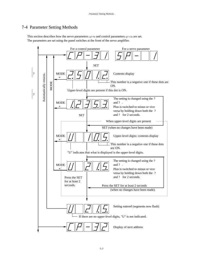
- Parameter Setting Methods -
7-4 Parameter Setting Methods
This section describes how the servo parameters (p7-9) and control parameters (p7-13) are set.The parameters are set using the panel switches at the front of the servo amplifier.
For a control parameter For a servo parameter
SET
? MODE Contents display*
Upper-level digits are present if this dot is ON.?
MODE*
SET
SET (when no changes have been made)
MODE Upper-level digits: contents display*
"U" indicates that what is displayed is the upper-level digits.
MODE*
Press the SET for at least 2 seconds(when no changes have been made).
Setting entered (segments now flash)
Display of next address
Aut
omat
ical
ly re
turn
s.
The setting is changed using the ?and ? .Plus is switched to minus or vice versa by holding down both the ?and ? for 2 seconds.
When upper-level digits are present
MO
DE
If there are no upper-level digits, "U" is not indicated.
This number is a negative one if these dots are ON.
The setting is changed using the ?and ? .Plus is switched to minus or vice versa by holding down both the ?and ? for 2 seconds.
This number is a negative one if these dots are ON.
Press the SET for at least 2 seconds.
7-7

- Parameter Setting Methods -
Changes in places with * are not reflected in the parameters.
Even when the value of the upper-level digits is zero for a parameter in which upper-level digits can be set, the upper-level digit will be displayed (as zero).
Changes made using the ? and ? are not carried down from the upper-level to low-order digits or carried up from the low-order to upper-level digits.
When zero is input as the value of lower-level digits for electronic gear a(p7-14) (control parameter 4) or ß(control parameter 5), the upper-level digit cannot be set to zero.
In this example, control parameter 31(CP-31) has been changed from "-10525012" to "-21512353".
7-8

- Servo parameters -
7-5 Detailed Description of Parameters
(1) Servo parameters
Servo parameters 1, 2, 3 and 11 through 19 can be changed during operation.Such changes immediately affect the operation.The other parameters can also be changed during operation.However, the changes will be made after the parameters are changed and the motor stops.
For speed command operation (p3-11)
Electric current
Speed
For position control (other than speed command operation)
Electric current
Position Speed
Default value
2000
No. Parameter Setting rangeARN15 ARN60 ARN135
AR10H
ARN30
Speed loop proportional gainSpeed loop integral gain
Position loop gain
1000
Other than AR10H
1800
These parameters are used to adjust the response characteristics of the motor. Increasing their numerical values increases the response characteristics.
In the equal pitch multi-rotation coordinates (p3-6), the optional division 360° coordinates (p3-7) and the infinite linear coordinates (p3-8) modes, if hunting has occurred on the servo actuator, infinite feed may not be possible. Adjust the gain properly.
123
1-150001-15000
1500-5000
2801800
5103300
150930 2000
270
MotorSpeed loop proportional gain
1/SSpeed loop integral gain
Electriccurrent loopSpeed command
MotorPositionloop gain
Speed loop proportional gain
1/SSpeed loop integral gain
Electric current loop
1/S
Position command
7-9

- Servo parameters -
To adjust or designate the parameters refer to the following table.
The rotation speed can be selected by speed selection (p6-12).
1000 1500 20002000 3000 4000
2000
Inertia moment ratio
Other than AR10H
AR10HSpeed loop proportional gain
Position loop gain
ARN30
Position loop gainARN15
Speed loop integral gain
ARN60
ARN135
Inertia moment ratio =Load moment of inertia [kg·m2] × 10000
Reduction gear ratio2 × Moment of inertia of motor [kg·cm2]
Speed loop proportional gain
Speed loop integral gainPosition loop gain
46002000
1 3 5
Speed loop proportional gain
2800Speed loop proportional gain
Speed loop proportional gain
Speed loop integral gain
5300550
150 290
2000
430930 1900
2000
Speed loop integral gainPosition loop gain
8201800 3500270
Speed loop integral gainPosition loop gain
32001800280 550 840
510 1000 1500
100
3300 4000 47002000
1 - 99999 [encoder pulses]
Default value
These parameters are for setting the motor rotation speed in the equal pitch multi-rotation coordinates (p3-6)
mode.
If the speed selections have not been allocated to control 1 to 14 (p6-10), speed 1 for equal division is automatically selected.
100
Default value7 Speed 1 for equal division 1 - 3000 [rpm] (AR135:2500)
Speed 2 for equal division
Parameter
8
1001 - 3000 [rpm] (AR135:2500)
Using the encoder's pulse units, this value indicates the angle of motor rotation, which is equivalent to four times the encoder source signal.
Setting range Default value
This parameter is for setting the skip amount during manual skip operations (p3-16) and I/O skip operation (p3-
15).
No. ParameterSkip amount6
No. Parameter Setting rangeManual feedrate4
No.100
1 - 3000 [rpm] (AR135:2500)
Setting range
These parameters are for setting the motor rotation speed and the acceleration/deceleration time constant during the I/O JOG (p3-12), the step operation (p3-13), the I/O skip operation(p3-15), the manual jog operation (p3-16)
and the manual skip operation (p3-16).
5 Manual feed acceleration/deceleration time constant 0 - 30000 [msec] 500
7-10

- Servo parameters -
The parameters denote the time taken from 0 to 3000 rpm at motor and vice versa.
These parameters are for setting the motor rotation speed during speed command operations (p3-11).Speed command speed 1 to 6 are selected by speed command speed selections 1 to 6 (p6-16).
13141516
Setting range Default value
1 - 3000 [rpm] (AR135:2500) 100
No. Parameter1112
Speed command speed 4Speed command speed 5Speed command speed 6
Speed command speed 1Speed command speed 2Speed command speed 3
910
No. Setting range
Acceleration/deceleration time constant 20 - 30000 [msec]0 - 30000 [msec]
500500
Acceleration/deceleration time constant 1Default valueParameter
Acceleration/deceleration time
constant 1Operation mode
Acceleration/deceleration time
constant 2
Infinite linear coordinates (p3-8) ? ?
?Acceleration/deceleration time
constant selection (p6-13)
-
When the acceleration/deceleration time constant selection (p6-13) is not allocated to controls 1 to 14 (p6-10) in the optional division 360° coordinates, the infinite linear coordinates or the finite linear coordinates mode, acceleration/deceleration time constant 1 is automatically selected.
Finite linear coordinates (p3-9)
? -Machine origin return (p3-14)
? ?
When the speed selection (p6-12) is not allocated to controls 1 to 14 (p6-10) in the equal pitch multi-rotation coordinates mode, acceleration/deceleration time constant 1 is automatically selected.
When these parameters are changed during operation, the speed is changed in accordance with the selected speed command acceleration/deceleration 1 to 3.If the speed command speed selections 1 to 6 have not been allocated to control 1 to 14 (p6-10) or if all the control signals are OFF even though they have been allocated, speed command speed 1 is automatically selected.
The following table shows the operation modes, the selected acceleration/deceleration time constants, and the selection function names.
Selection function name (Control allocation (p6-10))
Equal pitch multi-rotation coordinates (p3-6)
Optional division 360° coordinates (p3-7)
?
?
? Speed selection (p6-12)
7-11

- Servo parameters -
0 - 30000 [msec]
These parameters are for setting the motor acceleration/deceleration time constants during speed command operations (p3-11).
Parameter
Speed command acceleration/deceleration 1 to 3 are selected by speed command acceleration/deceleration selections 1 to 3 (p6-17).
18
No.
The parameters denote the time taken from 0 to 3,000 rpm at motor and vice versa.If the speed command acceleration/deceleration selections 1 to 3 have not been allocated to control 1 to 14 (p6-
10) and if all the control signals are OFF even when they have been allocated, speed command acceleration/deceleration 1 is automatically selected.
Speed command acceleration/deceleration 3
Setting range Default valueSpeed command acceleration/deceleration 1Speed command acceleration/deceleration 2 500
19
17
7-12
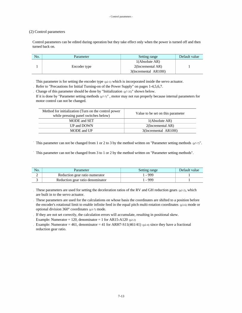
- Control parameters -
(2) Control parameters
This parameter is for setting the encoder type (p2-1) which is incorporated inside the servo actuator.Refer to "Precautions for Initial Turning-on of the Power Supply" on pages 1-4,5,6,7.Change of this parameter should be done by "Initialization (p7-35)" shown below.
If they are not set correctly, the calculation errors will accumulate, resulting in positional skew.Example: Numerator = 120, denominator = 1 for AR15-A120 (p2-2)
Parameter Setting range
13(Incremental AR10H)
Encoder type1(Absolute AR)
2(Incremental AR)
No.
32
No.
1
This parameter can not be changed from 1 or 2 to 3 by the method written on "Parameter setting methods (p7-7)".
2(Incremental AR)3(Incremental AR10H)
Default value
Default value
Example: Numerator = 461, denominator = 41 for ARH7-S11(461/41) (p2-4) since they have a fractional reduction gear ratio.
If it is done by "Parameter setting methods (p7-7)" , motor may not run properly because internal parameters for motor control can not be changed.
11 - 999
Reduction gear ratio denominator
This parameter can not be changed from 3 to 1 or 2 by the method written on "Parameter setting methods".
1 - 999Reduction gear ratio numerator
Parameter Setting range
Control parameters can be edited during operation but they take effect only when the power is turned off and then turned back on.
Method for initialization (Turn on the control power while pressing panel switches below)
These parameters are used for setting the deceleration ratios of the RV and GH reduction gears (p2-2), which are built in to the servo actuator.These parameters are used for the calculations on whose basis the coordinates are shifted to a position before the encoder's rotational limit to enable infinite feed in the equal pitch multi-rotation coordinates (p3-6) mode or optional division 360° coordinates (p3-7) mode.
UP and DOWNMODE and UP
1(Absolute AR)MODE and SET
Value to be set on this parameter
1
7-13

- Control parameters -
= Electronic gear a
= Electronic gear ß
In the case of pulse train operations (p3-10), the motor rotates by an amount equivalent to: Number of input pulses (p7-18) × electronic gear a/electronic gear ß.These parameters have no effect in the equal pitch multi-rotation coordinates (p3-6) mode and speed command operation (p3-11) mode.
The 123.45° position data in this case yields a setting of 12345. (Positioning position = Position data × unit amount)
6 1 , 2 , 3 , 4 , 5
360° ×120
0.1
Incremental (other than AR10H)
1
Unit amount (resolution) Position data setting rangeSetting
× Unit amountElectronic gear ß
(In the optional division 360° coordinates (p3-7) mode, the "Unit amount × Position data" value is less than 360.)
Machine system movement amount per motor rotation4 × number of encoder pulses
Absolute
AR10H
2048
360
20001000
Calculation example: Reduction gear ratio = 120, unit amount = 0.01°, overview of machine system = rotary table drive, encoder type = absolute
2048
Encoder type No. of pulses
11Electronic gear ß
1 - 999999 (6 digits)Electronic gear a1 - 999999 (6 digits)
Electronic gear a=
45
The correlation between the settings and the unit amounts (resolution) and their position data setting range is shown below.
No. Parameter Setting range Default value
These electronic gear settings are provided to enable the movement amount of the machine output end to be directly assigned using physical quantities (mm, deg, etc.). Setting these parameters makes it possible to input the position data (p7-33) directly as physical quantities.
In the equation below, the electronic gears a and ß are determined on the basis of the unit amount which is the resolution of the position data and the amount by which the machine output end moves for each motor rotation.
Unit amount
0.010.001
0.0001
1234
±999999999 (9 digits)[unit amount]
=120360
Machine system movement amount per motor rotation =1
1
(before multiplication by 4)Number of encoder pulses (p2-2)
5
75
4 × number of encoder pulsesMachine system movementamount per motor rotation
× Unit amount8192300
==4×2048×120×0.01
7-14

- Control parameters -
This parameter is for enabling or disabling the brake power (p5-14) supply disconnection alarm (p9-3).
Set "2" (unavailable) when using a servo actuator (p2-1) which is not equipped with a brake.The brake power is checked only at the ON edge of the operation ready command (p6-9).
This parameter is for setting the coordinate axes (p3-5).Equal pitch multi-rotation coordinates (p3-6) :1 Finite linear coordinates (p3-9) :4Optional division 360° coordinates (p3-7) :2 Pulse train operation (p3-10) :5Infinite linear coordinates (p3-8) :3 Speed command operation (p3-11) :6
This parameter is for setting the number of addresses per rotation of the servo actuator.
This parameter is for setting the total number of addresses.
In the case of the figure on the right, this parameter's setting is 10.
As shown in the figure on your right, when position is 0 degrees and position is 270 degrees, if the servo actuator is to be positioned to from , route ? uses a short-cut control and route does not use such a control.
Optional division short-cut control 1
22 - 255
Parameter Setting range Default value
Coordinate axis
1 (available), 2 (unavailable) 1
Setting range
No.
No.
7
Parameter
Parameter
When "1" is set in the parameter, the brake power supply disconnection alarm AL-10 is output when the brake power fails to be supplied.
Setting range Default valueBrake available/unavailable
Default value
2 - 255Parameter Setting range Default value
Number of divisions 2
8 1 , 2 , 3 , 4 , 5 , 6 1
1 (available), 2 (unavailable)
No.9
10
11
No.
No.
CP-14 is used to enable or disable short-cut control in the equal pitch multi-rotation coordinates (p3-6) mode.Note that setting this parameter to "2" (disabled) rotates the output shaft at the end of the following sequence: Positioning to 0° address ? Servo OFF ? Slight positional shift after the motor power shuts off ? For example, when the output shaft is positioned at 359°. ? Instruction for positioning the output shaft to 0°.? The output shaft rotates one turn.
It is valid only when the equal pitch multi-rotation coordinates (p3-6) mode has been selected (coordinate axes CP-8=1).As in the case of the drawing for control parameter No. 10 below, the number of addresses per rotation of the servo actuator output shaft is 4 (= 360/90) in this parameter because the movement of the output shaft is demarcated by 90-degree increments.
It is valid only when the equal pitch multi-rotation coordinates (p3-6) mode has been selected (coordinate axes CP-8=1).
This parameter is for enabling or disabling short-cut control in the optional division 360° coordinates (p3-7) mode.
Parameter Setting range Default valueTotal number of addresses
Servo actuator
7-15

- Control parameters -
Note 1:
NC system advances to the next block.Start(MF signal of NC system) Note 1
Positioning completion signal (FIN signal of NC system) Stop after deceleration
Motor rotation speed
Set "1" for short cut, "2" for current position incrementing direction, and "3" for current position decrementing direction.For details on the settings and rotation direction of the servo actuator output shaft, refer to the section on the input signals, parameters and servo actuator rotation directions on p3-26."3" is the setting when indexing in the direction shown in the figure using AR**A. Refer to p3-26.
No. Parameter13
Setting range
OFFON
1 (available), 2 (unavailable)
14No. Parameter
This parameter is for setting the indexing direction with unidirectional indexing in the equal pitch multirotation coordinates (p3-6) mode.
Setting range Default valueShort-cut/unidirectional selection 11 , 2 , 3
12 1 , 2 1No. Setting range Default value
Indexing number incrementing directionParameter
This parameter is for setting the rotation direction in which the indexing address numbers (p6-11) are incremented.It is valid only when the equal pitch multi-rotation coordinates (p3-6) mode has been selected (coordinate axes CP-8=1)."1" is set as the current position incrementing direction and "2" as the current position decrementing direction.For details on the rotation direction of the servo actuator output shaft, refer to the section on the input signals, parameters and servo actuator rotation directions on p3-26."1" is the setting when the addresses are to be incremented in the direction shown in the figure using AR**A. Refer to p3-26.
When this parameter is set to "1" (available), the positioning completion signal (p6-19) is turned off in synchronization with the turning OFF of the start signal (p6-10).
If the start signal is turned off before the positioning completion signal is turned on, the motor decelerates and ultimately stops. Therefore, the positioning completion signal will fail to turn on.
This parameter is used for interfacing with the M functions of the NC system, in which case the start signal serves as the MF signal of the NC system and the positioning completion signal serves as the its FIN signal.
Default value2MF/FIN available/unavailable
Servo actuator (output shaft side)
CW
Servo actuator (output shaft side)
Increases in CCW direction
7-16

- Control parameters -
The setting for indexing using AR**A is shown in the figure below. Refer to p3-26.In this figure, the servo actuator is seen from the output shaft side.
CCW CWSetting = 1
CW CCWSetting = 2
No.
This parameter is for setting the indexing direction with 2-position indexing in the equal pitch multi-rotation coordinates (p3-6) mode.
It takes effect when the number of divisions (CP-9) is set to "2", the total number of addresses (CP-10) is "2" and short-cut/unidirectional selection (CP-14) is "1".
1 , 2 1Parameter Setting range Default value
2-position indexing direction selection
Setting "1": Address #1 ? rotation in current position incrementing direction ? address #2 ? rotation in current position decrementing direction ? address #1.
Setting "2": Address #1 ? rotation in current position decrementing direction ? address #2 ? rotation in current position incrementing direction ? address #1.
For details on the settings and rotation direction of the servo actuator output shaft, refer to the section on the input signals, parameters and servo actuator rotation directions on p3-26.
15
Address #1
Address #2
Address #1
Address #1
Address #2
Address #1
1
2 1
2 1
2
1
2 1
2 1
2
7-17

- Control parameters -
This parameter is for setting the input pulse format when performing pulse train operations (p3-10).
A-IN (p5-9): 300 kpps max1.5 µ sec min
B-IN (p5-9)
3 µ sec min1.5 µ sec min
A-IN: 150 kpps max
B-IN
Past Elapsed time Present
This parameter is for setting the motor rotation direction during pulse train operations.Refer to the above figure for the correlation between the setting and rotation direction.
CP17=1
CP17=2Motor rotation direction
Current position incrementing direction
Current position decrementing direction
1.5 µ sec min
1(Foward pulse reverse pulse)Input pulse system 1
2(90 phase difference 2 signals)
Input pulse system
For details on the input pulses and rotation direction of the servo actuator output shaft, refer to the section on the input signals, parameters and servo actuator rotation directions on p3-26.
ON in the table below denotes a state in which power is supplied to the p5-9 pulse train input circuit LED.
16
OFF
Default value
2 signals
Parameter
Reverse pulse 1.5 µ sec min
The motor rotates by an amount equivalent to the value obtained from: number of input pulses × electronic gear a/electronic gear ß(p7-14).
and numbers are input pulse numbers.Input pulse count
OFF
Parameter Setting rangeNo.
1.5 µ sec minCP16=2
Default value17 1 , 2 1Pulse train operation rotation direction
OFF90° phase difference
OFF
No.
Forward pulse
CP16=1
Setting range
Current position incrementing direction
Current position decrementing direction
7-18
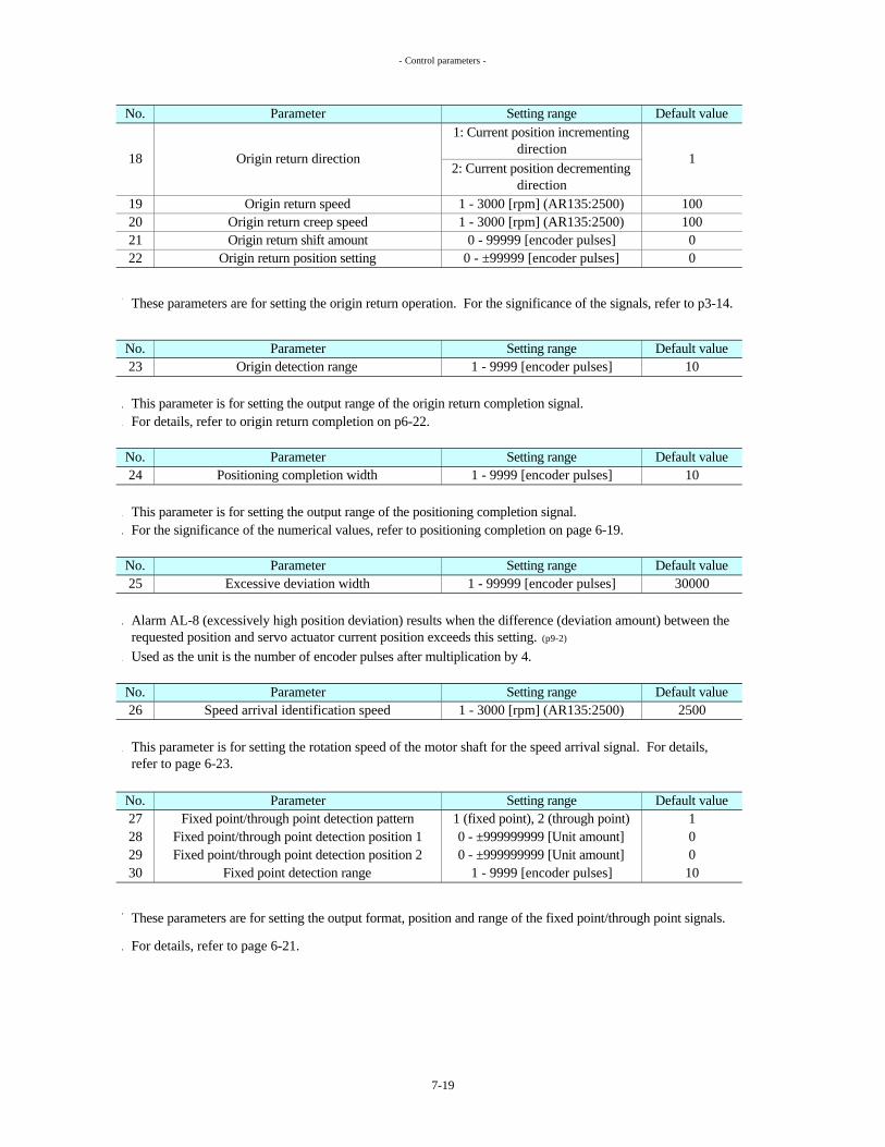
- Control parameters -
This parameter is for setting the output range of the origin return completion signal.For details, refer to origin return completion on p6-22.
This parameter is for setting the output range of the positioning completion signal.For the significance of the numerical values, refer to positioning completion on page 6-19.
Used as the unit is the number of encoder pulses after multiplication by 4.
For details, refer to page 6-21.
These parameters are for setting the output format, position and range of the fixed point/through point signals.
22 0
No.23
These parameters are for setting the origin return operation. For the significance of the signals, refer to p3-14.
Origin return position setting 0 - ±99999 [encoder pulses]
Default valueOrigin detection range
1 - 3000 [rpm] (AR135:2500)1 - 3000 [rpm] (AR135:2500)
0 - 99999 [encoder pulses]
19
No.
Origin return creep speedOrigin return shift amount
Origin return speed
18
2021
Default valueParameter Setting range
0
100100
1Origin return direction
1: Current position incrementing direction
2: Current position decrementing direction
Parameter Setting range101 - 9999 [encoder pulses]
Parameter Setting range
2728
Alarm AL-8 (excessively high position deviation) results when the difference (deviation amount) between the requested position and servo actuator current position exceeds this setting. (p9-2)
This parameter is for setting the rotation speed of the motor shaft for the speed arrival signal. For details, refer to page 6-23.
Parameter Setting range
26
1
Fixed point detection range29
Default value2500Speed arrival identification speed
No. Parameter Setting range1 - 3000 [rpm] (AR135:2500)
No.
00
1 - 9999 [encoder pulses]
1 (fixed point), 2 (through point)0 - ±999999999 [Unit amount]0 - ±999999999 [Unit amount]
30
3000025 1 - 99999 [encoder pulses]Excessive deviation width
Default valueFixed point/through point detection pattern
Fixed point/through point detection position 1Fixed point/through point detection position 2
10
Default valuePositioning completion width
No. Parameter Setting range Default value
10No.24 1 - 9999 [encoder pulses]
7-19

- Control parameters -
This parameter is for setting the maximum rotation speed of the motor shaft.
The brake cannot be released while the operation ready command signal (p6-9) is off.When “1” (release) is selected, the power save timer function (CP-39) (p7-21) is deactivated.
21 (release), 235No. Parameter Setting range Default value
Default value
350
Soft + over-travel detection position
Soft - over-travel detection position
0 - ±999999999 [encoder pulses]0 - ±999999999 [encoder pulses]
+999999999
-999999999
Parameter Setting range
Torque limit value350350
AR135 , ARH24: 0 - 300
Note that, if an unbalanced load is applied to the output shaft, the servo actuator may be rotated by an external force.
When setting "1" is selected, the holding electromagnetic brake (p5-14) is released regardless of whether the servo ON signal (p6-9) is ON or OFF.
When “1” (release) is selected and the operation ready command signal turns ON, the brake is released.
31
32
Parameter
No.
When an attempt is made to feed the servo actuator beyond either of these settings, the servo actuator is stopped immediately at the position of the setting.In this case, the control output over-travel detection signal (p6-22) turns on, and then "AL-17" (Soft over-travel detection, p9-4) is displayed.These parameters are valid only in the finite linear coordinates (p3-9), pulse train operation (p3-10) and machine origin return (p3-14) modes.
Parameter Setting rangeNo.
Brake forcible release
No.
34
AR15: 0 - 350AR30 , ARH7: 0 - 350
AR60 , ARH17: 0 - 350
AR10H
Even in the over-travel detection status, the servo actuator can be rotated in the direction opposite to the over-travel detection direction.
Default value
(ARN135:2500)3000
Do not set the parameters where the soft + over-travel detection position is less than the soft - over-travel detection position, or else “AL-17” (Soft over-travel detection, p9-4) will occur in the finite linear coordinates mode (p3-9), the pulse train operation (p3-10) and machine origin return (p3-14) modes.
This parameter is for setting the torque limit value of the motor shaft. The rated torque is treated as 100%.
The parameter is valid during the ON period of the control input signal's torque limiting enable (p6-12) signal.
The torque limiting underway (p6-24) signal turns on while the torque is being limited by this parameter's setting.
33 Speed limit value 1 - 3000 [rpm] (AR135:2500)
350300
Setting range Default value
7-20

- Control parameters -
This parameter is used for setting the range wherein the home position signal (p6-23) turns on.For details, refer to the home position on page 6-23.Used as the unit is the number of encoder pulses after multiplication by 4.
These parameters are used to correct the error resulting from machine system backlash.
These parameters are valid only in the equal pitch multi-rotation coordinates (p3-6).
Requested position Stop positionBacklash compensation direction
Backlash compensation amount
When the start signal (p6-10) turns on after this, the brake is released, and operation is commenced.
These parameters are invalid when the brake forcible release (CP-35) has been set to “1” (release).
Number of encoder pulses × reduction gear ratio
1 (current position incrementing direction)
2 (current position decrementing direction)
1
The amount moved by the output shaft of the servo actuator is calculated using the following formula.
When the servo actuator is to be rotated in the designated direction, it is positioned at the position resulting when the backlash compensation amount is added to the target position.
The unit used for the backlash compensation amount is the number of encoder pulses after multiplication by 4.
Parameter
Backlash compensation direction38
No.
Backlash compensation amount37
No.1 (available), 2 (unavailable)
Setting range
0
Default valueHome position detection range
0 - 9999 [encoder pulses]
8001 - 9999 [encoder pulses]Parameter
These parameters are for reducing the heat generated by the motor if it is stopped when torque has been applied for a prolonged period of time.
39
36
No.
Backlash compensation amount × 360Amount compensated by output shaft [°] =
3040
Setting range
Power save timer time
These parameters are valid only when the coordinate axis (CP-8, p7-15) has been set to “1” and the equal pitch multi-rotation coordinates mode (p3-6) has been selected for the main operation mode (p3-5).
2
Setting range Default value
For details on the backlash compensation direction and rotation direction of the servo actuator output shaft, refer to the section on the input signals, parameters and servo actuator rotation directions on page 3-26.
When the time set by the power save timer parameter is reached after the servo ON status has been established and no position commands are in force, the servo ON (p6-9) signal automatically turns off, and the brake (p5-14)
is engaged.
Power save timer available/unavailableParameter
30 - 9999 [sec]
Default value
7-21

- Control parameters -
Rotation speed Overshoot amount
Target position
This function is executed when the servo ON signal is turned ON, then OFF and back ON again.The function is disabled if zero is set for the parameter's setting.Used as the unit is the number of encoder pulses after multiplication by 4.
This parameter is for selecting the contact logic of the interlock signal.
For details on the interlock function, refer to interlock on page 6-18.
0Parameter Setting range Default valueNo.
41
42
0 - 9999 [encoder pulses]Overshoot amount
No. Parameter Setting range
Position
The holding torque in the servo lock status may be boosted by distortion in the machine system resulting from a frictional load.
1 , 2 143 Interlock logic
Set the overshoot amount to the optimum level while checking the holding torque.
Positional skew equivalent to the amount of play between the brake and motor shaft may occur when the servo ON (p6-9) signal is turned ON, then OFF and back ON again.
During positioning, the servo actuator passes through the target position by an amount equivalent to this parameter's setting, and then it returns to the target position.
This parameter enables the machine system distortion to be reduced so that the holding torque is lowered.
By passing through and returning to the target position, the machine system distortion (hysteresis) is eliminated, and the servo lock torque is reduced.
When a number of pulses other than zero has been set in this parameter, the positioning time is slightly longer than when zero has been set.
Default valueNumber of follow-up pulses 0 - 1000[encoder pulses] 0
This function is valid only when the equal pitch multi-rotation coordinates (p3-6) mode has been selected (coordinate axes : CP-8=1).
At the "1" setting, rotation is prohibited when the signal is ON; at the "2" setting, rotation is prohibited when the signal is OFF.
This function is valid only when the equal pitch multi-rotation coordinates (p3-6) mode has been selected (coordinate axes : CP-8=1).
Used as the unit is the number of encoder pulses after multiplication by 4.
No. Parameter Setting range Default value
This parameter is used to correct this skew.The current position is ignored and positioning occurs at the indexing address requested position only when the difference between the indexing address requested position and current position is less than the setting of this parameter.
7-22

- Control parameters -
Even in the rewriting prohibited mode, only this parameter can be rewritten.Even in the rewriting prohibited mode, initialization on page 7-35 can be executed.
For torque display purposes, the rated torque is treated as 100%.
Return Linear
2.5V
-3000rpm 3000rpm -3000rpm 3000rpm-500% 500% -500% 500%
Default valueMonitor selection
Motor rotation speed monitor (channel A) Torque monitor (channel B)
1 , 2 , 3 , 4
5V
1
Return
4 Linear
LinearReturnLinear
VoltageVoltage
TorqueMotor rotation speed
3
0
ReturnReturnLinear
12
00
5V
No. Parameter Setting range
Setting range
0
45
Setting
Default value
This parameter is for selecting the scale of the monitor connector (p5-2,3) on the side panel of the servo amplifier.
44 Rewriting prohibited1 (not prohibited)
1
When "2" has been set, rewriting of the servo parameters (p7-9), control parameters and positioning data (p7-33)
is prohibited.
2 (prohibited)
No. Parameter
7-23

- Control parameters -
The correlation between the settings and display contents is shown below.
Software version
Requested pulseAlarm history
Digital input monitorDigital output monitor
Requested positionPercentage torqueDeviation pulseFeedback pulse
Motor rotation speedDisplay content
Position address numberCurrent position
89
10
1211
4567
Setting123
This parameter is for selecting what is to be displayed immediately after the power has been turned on.
No. Parameter Setting range Default value46 1 - 12 1Display contents when power is turned on
Immediately after the power has been turned on, the 7-segment LED is set to the display mode and displays the display contents below. (p7-1)
7-24

- Control parameters -
These parameters are for setting the functions to be allocated to control 1 to 14 (p6-10).For details on the functions, refer to control 1 to 14 on page 6-10.
Setting range
Control 11
28:29:
FWDLSORG- over-travel+ over-travel
Control 7
605958
47484950
54
5756
22:23:
37 Speed selection
24:25:
38 LS
26:
21:
23 Interlock
39 ORG
18:19:
16:17:
15:
20:
14:
Control 12Control 13 12:
13:Control 14
5521
Control 8Control 9 Control 10
10:11:
19 AD7RVSFWD
8:9:
7:20
9 AD6
7 AD451
6:
4:5:8 AD5
5352
Control 5 Control 6
Control 3 5 AD23:2:
Control 4 6 AD3
Control 2 4 AD1Control 1 3 AD0
Speed command speed selection 2Speed command speed selection 1RVS
0:1:
ParameterCN2
Default valueNo.
Speed command speed selection 6Speed command speed selection 5Speed command speed selection 4Speed command speed selection 3
Speed command acceleration/deceleration selection 2Speed command acceleration/deceleration selection 3
For settings other than "0", if the same setting is specified for two or more symbols from CONT1 through CONT14, the setting for the CONT symbol with the highest number will be in effect.
Speed command acceleration/deceleration selection 1
Interlock
27:
Acceleration/deceleration time constant selectionSpeed selectionExternal failure inputTorque limiting enableP operationAD7AD6
No function designatedAD0AD1AD2AD3AD4AD5
7-25

- Control parameters -
These parameters are for setting the functions to be allocated to out 1 to 15 (p6-19).For details on the functions, refer to out 1 to 15 on page 6-19.Two or more of the same functions can be set.
This parameter is for setting the function when MODE A and MODE B is ON.
This parameter is not for users, but for Teijinseiki co., Ltd. to check this servo amplifier.
77 Factory use (Not for users) --
For details, refer to "How to select the operation mode (p3-5)", "I/O skip operation (p3-15)", "Machine origin return (p3-14)", "Main operation modes, and selectable sub operation modes and manual operation modes (p3-
17)".
No. Parameter Setting range Default value
01(I/O skip operation)
1Machine origin return
I/O skip operation
Setting Sub operation mode0
No. Parameter Setting range
76 Sub operation mode switch0(Machine origin return)
Default value
0: No function designatedOUT-AD0
10:
14:13:
11:12:
OUT-AD5
Setting range
63
Default value
61 11 OUT-AD0No.
Parameter
Out 2
OUT-AD4
71 Out 11 41
OUT-AD616
Origin return completion
OUT-AD5
OUT-AD7Out 9
65 15
67 27
Servo ON/OUTOut 12
Home position
Out 7Out 8
Out 13
68 28
66
OUT-AD7
Fixed point/through point 1Operation underway
73
72 42
69 2970 30
OUT-AD6
OUT-AD1OUT-AD2OUT-AD3OUT-AD4
9:
15:
Servo ON/OUT
Alarm detection
20:
18:19:
74
75 Operation underway32Out 15
Out 14 44Fixed point /through
point 1
Operation ready completion
43
Home positionTorque limiting underway
Origin return completionOver-travel detectionFixed point/through point 2
16:17:
Positioning completion
Speed arrival
CN2
Out 1
Out 3 13
Out 10 Operation ready completion
Out 5Out 6 5:
7:6:
Alarm detection 8:
1:
3:2:
4:64 14 OUT-AD3
62 12 OUT-AD1OUT-AD2
Out 4
7-26

- Control parameters -
When CP-78 is 1(available), following operation are performed.
Servo amplifier compares "Position ON" and "Position OFF".
If | Position ON - Position OFF | > CP-79 then "AL-19 , Positon defect (p9-5) " is displayed.
This function is valid only when all of the following conditions are available.This function is invalid if one of the following conditions is unavailable.
CP-1 (p7-13) = 1 : Absolute ARCP-7(p7-15) = 1 :Brake availableCP-8 (p7-15) = 1 : Equal pitch multi-rotation coordinates (p3-6).Encorder selector switch (p5-2,3) = ABSNo command to rorate motor is executed when control power (p5-10) is turned OFF.Battery (p5-19) is connected to servo amplifier.
Used as the unit of CP-79 is the number of encoder pulses after multiplication by 4.(8192 pulse/motor revolution : absolute encoder)
Position defect alarm available/unavailable1(available)
2
Servo amplifier memorizes the position of servo actuator when control power (p5-10) is turned OFF. (This position data is named "Position OFF")
2(unavailable)78
Servo amplifier memorizes the position of servo actuator when control power is turned ON. (This position data is named "Position ON")
Servo amplifier checks the data in encoder when control power is turned ON, therefor more severe system check is possible with this function.
AL-19 (p9-5) may be displayed if servo actuator is rotated by external force when control power is OFF and this function is ON.
Position defect alarm width79 800~9999[encoder pulses] 9999
Default valueNo. Parameter Setting range
7-27

- List of Parameters -
7-6 List of Parameters(1) Servo parameters
(2) Control parameters
1
1
100
ARN15:930
ARN135:3300
ARN30:1800ARN60:1800
100
100
Default value
No. Parameter
5 Manual feed acceleration/deceleration time constant (p7-10)
4
1 Speed loop proportional gain (p7-9)
3
Setting range Default valueARN15:150
1 - 15000
ARN135:510
ARN30:270ARN60:280
1(1), 2(0.1), 3(0.01), 4(0.001), 5(0.0001)
7 1 (available), 2 (unavailable)Brake available/unavailable (p7-15)
19
1 Encoder type (p7-13)
6
2345 Electronic gear ß (p7-14)
No. Parameter
11
1 - 3000 [rpm] (AR135:2500)
121314
16
17
18
Speed command speed 1 (p7-11)
2000
1 - 15000
7 Speed 1 for equal division (p7-10)1 - 3000 [rpm] (AR135:2500) 100
8 Speed 2 for equal division (p7-10)
6 1 - 99999 [encoder pulses]Skip amount (p7-10)
2 Speed loop integral gain (p7-9)
0 - 30000 [msec]
1 - 3000 [rpm] (AR135:2500)Manual feedrate (p7-10)
1500 - 5000Position loop gain (p7-9)
Reduction gear ratio numerator (p7-13)
Reduction gear ratio denominator (p7-13)
Electronic gear a (p7-14)
Unit amount (p7-14)
1 - 999999 1
3 (AR10H)
Setting range1 (Absolute AR)
2 (Incremental AR) 1
1 - 999 1
Speed command speed 3 (p7-11)
Speed command speed 6 (p7-11)
Speed command speed 4 (p7-11)
500
Speed command acceleration/deceleration 1 (p7-12)
Speed command acceleration/deceleration 2 (p7-12)
Speed command acceleration/deceleration 3 (p7-12)
0 - 30000 [msec]
500
15 Speed command speed 5 (p7-11)
9 Acceleration/deceleration time constant 1 (p7-11)
Acceleration/deceleration time constant 2 (p7-11)
100 - 30000 [msec] 500
Speed command speed 2 (p7-11)
7-28
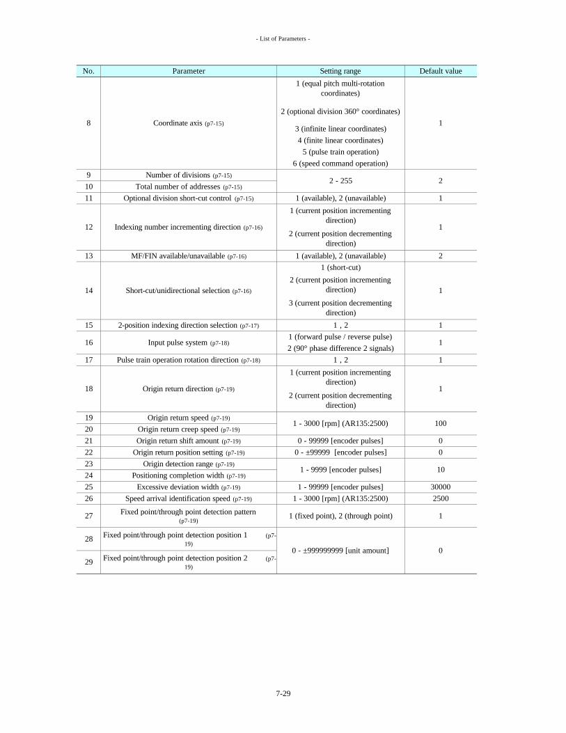
- List of Parameters -
0
1
14 Short-cut/unidirectional selection (p7-16)
1 (short-cut)
Origin return position setting (p7-19)
Origin detection range (p7-19)
Positioning completion width (p7-19)10
0
30000
No. Parameter
0
19 Origin return speed (p7-19)
20
2
1
17
2500
Setting range
23
2524
100
22 0 - ±99999 [encoder pulses]
Origin return creep speed (p7-19)
21
0 - ±999999999 [unit amount]
1 - 99999 [encoder pulses]26 1 - 3000 [rpm] (AR135:2500)Speed arrival identification speed (p7-19)
Fixed point/through point detection position 1 (p7-19)
28
29 Fixed point/through point detection position 2 (p7-19)
Excessive deviation width (p7-19)
27 Fixed point/through point detection pattern (p7-19)
18
1 (fixed point), 2 (through point)
0 - 99999 [encoder pulses]Origin return shift amount (p7-19)
1 - 9999 [encoder pulses]
Pulse train operation rotation direction (p7-18)
Origin return direction (p7-19)
1 (current position incrementing direction)
2 (current position decrementing direction)
16 Input pulse system (p7-18)
MF/FIN available/unavailable (p7-16)13
2-position indexing direction selection (p7-17)15
Coordinate axis (p7-15)
2 (current position incrementing direction)
3 (current position decrementing direction)
5 (pulse train operation)6 (speed command operation)
3 (infinite linear coordinates)4 (finite linear coordinates)
1 (available), 2 (unavailable)
1
110
Optional division short-cut control (p7-15)
Number of divisions (p7-15)
11 1 (available), 2 (unavailable)
9Total number of addresses (p7-15)
8
Default value
12 Indexing number incrementing direction (p7-16)
1 (current position incrementing direction)
2 (current position decrementing direction)
1
2 - 255 2
2 (optional division 360° coordinates)
1 (equal pitch multi-rotation coordinates)
1
1 - 3000 [rpm] (AR135:2500)
1 , 2
12 (90° phase difference 2 signals)
1
11 (forward pulse / reverse pulse)
1 , 2
7-29

- List of Parameters -
Default value
41 0 - 9999 [encoder pulses]Overshoot amount (p7-22)
36 1 - 9999 [encoder pulses]2
Backlash compensation amount (p7-21)
34
AR15: 0 - 350
42 0 - 1000 [encoder pulses]Number of follow-up pulses (p7-22)
39 1 (available) , 2 (unavailable)Power save timer available/unavailable (p7-21)
40 30 - 9999 [sec]Power save timer time (p7-21)
10
AR30, ARH7: 0 - 350AR60, ARH17: 0 - 350
AR10H
+999999999-999999999
3000350350350
46
33
1 (motor rotation speed)
1 - 3000 [rpm] (AR135:2500)
35 1 (release) , 2
37
1 (rotation prohibited when ON)
7 (feedback pulse)8 (requested pulse)
Display contents when power is turned on (p7-24)
Brake forcible release (p7-20)
11 (digital output monitor)12 (software version)
9 (alarm history)10 (digital input monitor)
Home position detection range (p7-21)
Setting range
Soft + over-travel detection position (p7-20)
Soft - over-travel detection position (p7-20)0 - ±999999999 [encoder pulses]
1 - 9999 [encoder pulses]Fixed point detection range (p7-19)
44 1 (not prohibited), 2 (prohibited)
432 (rotation prohibited when OFF)
Rewriting prohibited (p7-23)
Interlock logic (p7-22)
452 (A=return, B=linear)3 (A=linear, B=return)4 (A=linear, B=linear)
1 (A=return, B=return)
Monitor selection (p7-23)
38 Backlash compensation direction (p7-21)
1 (current position incrementing direction)
2 (current position decrementing direction)
3000
1
1
1
1
3 (current position)4 (requested position)5 (percentage torque)
6 (deviation pulse)
2 (position address number)
No. Parameter
0
2
AR135, ARH24: 0 - 300 300
1
0 - 9999 [encoder pulses]
350
800
Speed limit value (p7-20)
Torque limit value (p7-20)
303132
7-30

- List of Parameters -
37
38
39
59
60
Control 1258
Control 14
Control 13
49
50
51
52
53
54
55
56
57
Control 10
Control 11
Control 3
Control 4
Control 5
Control 6
Control 7
Control 8
Control 9
ORG
9
19
20
21
23
FWD
5
6
7
8
Interlock
Speed selection
LS
AD4
AD5
AD6
AD7
RVS
AD0
AD1
AD2
AD3
48 Control 2 4
3
Speed selection (p6-12)
ORG (p6-14)
- over-travel
AD5AD6
External failure input (p6-12)
Torque limiting enable (p6-12)
Acceleration/deceleration time constant selection (p6-13)
Speed command speed selection 6
Interlock (p6-18)
Speed command acceleration/deceleration selection 1 (p6-17)
AD3
P operation (p6-12)
Speed command speed selection 5
FWD (p6-15)
LS (p6-14)
AD4
+ over-travel (p6-13)
No.
AD7
CN2 No.
AD0 (p6-11)
No function designated (p6-10)
7:
3:
6:
47 Control 1 (p6-10)
29:
23:
21:22:
27:
28:
Speed command speed selection 4Speed command speed selection 3Speed command speed selection 2Speed command speed selection 1 (p6-16)
8:
5:4:
RVS (p6-15)
10:
13:
11:12:
14:
17:
Parameter Setting rangeDefault value
AD2AD12:
0:1:
9:
15:
Speed command acceleration/deceleration selection 2
Speed command acceleration/deceleration selection 3
20:
16:
24:25:
18:
26:
19:
7-31

- List of Parameters -
75 Out 15 32 Operation underway
6:275:16
30
Servo ON/OUT
16:
Out 11 41Origin return completion 11:
Operation ready completion
Out 13 43
Out 4Out 5
OUT-AD5OUT-AD6
OUT-AD3OUT-AD4
Home positionServo ON/OUT (p6-20)
Operation underway (p6-21)
18:Speed arrival (p6-23)
Fixed point/through point 1
Alarm detection (p6-23)
Origin return completion (p6-22)
10:
13:
OUT-AD1
Setting rangeDefault valueOut 1 (p6-19) 0:11
6968
65
29OUT-AD728
Alarm detection
Out 6
Out 10
2:
14:
72
9:8:7:
Out 7Out 8Out 9
279 Position defect alarm width (p7-27) 800 - 9999 999978 Position defect alarm available/unavailable (p7-27) 1 (available) , 2 (unavailable)
-
Fixed point/through point 1 (p6-21)
1 (I/O skip operation)
71
12:Out 12 42
74 Out 14 44
20: Positioning completion (p6-24)
17:
Over-travel detection (p6-22)
Torque limiting underway (p6-24)
Home position (p6-23)
77 -
70
Fixed point/through point 2
Factory use (Not for users) (p7-26)
Operation ready completion (p6-20)
Default valueParameter Setting range
19:
Sub operation mode switch (p7-26)76
1:
4:1415
3:
No.
73
15:
No. CN2 No.
6263
1213
61Parameter
Out 2Out 3
0 (Machine origin return)0
OUT-AD4OUT-AD3
OUT-AD6OUT-AD5
64
OUT-AD7
OUT-AD0 (p6-20)
No function designated (p6-19)
OUT-AD2OUT-AD1
67 66
OUT-AD0
OUT-AD2
7-32

- Positioning Data Setting Method -
7-7 Positioning Data Setting Method
The method used to set this positioning data will be described.
The positioning data can be set using the panel switches in front of the servo amplifier.
The positioning data includes the following.
Press MODE for 2 sec.
Press MODE for 2 sec.Press MODE for 2 sec.
Press MODE for 2 sec.
Press MODE for 2 sec.
Control parameters
Manual operation mode
Position data editing mode
?
?
?
?
Servo parameters
The positioning data can be edited during operation.The edited data is in effect when the Start input signal (p6-
10) turns ON.
Position data: For setting the target position; unit = [unit amount (p7-14)], setting range = -999999999 to +999999999 (9 digits).(In the optional division 360° coordinates mode (p3-7), the “Unit amount x Position data” value is equal to or greater than 0 and is less than 360. If the address of a value less than 0 or equal to or greater than 360 is started, an Address error (AL-16, p9-4) occurs.)
In the case of optional division 360° coordinates (p3-7), infinite linear coordinates (p3-8) and finite linear coordinates (p3-9) operations, the positioning data inside the servo amplifier is used for positioning.
Motor rotation speed: For setting the rotation speed of the motor; unit = [rpm], setting range = 0 to 3000 (AR135: 2500)
Operate the mode switch on the front panel of the servo amplifier to establish the positioning data editing mode (p7-2).Refer the figure below.
Display mode
7-33

- Positioning Data Setting Method -
Address number (p6-11)
MODE Display of low-order 5 digits of position data
*
MODE The setting is changed using the ? and ? .*
? SET (when no changes have been made)MODE Display of high-order 4 digits of position data
*This number is a negative one
? P(Position) if these dots are lighted.MODE The setting is changed using the ? and ? .
*
SET (when no changes have been made)MODE Display of motor rotation speed
*
S(Speed)MODE The setting is changed using the ? and ? .
*
Press the SET for at least 2 seconds.(when no changes have been made.)
Setting entered (segments now flash)
Changes in places with * are not reflected in the parameters.
The default values are 0 for the position data and 0 rpm for the motor rotation speed.
When ? is held down, the displayed figure will reach the maximum value which is then followed by the minimum value.
SET
SET
Even when the value of the high-order digits is zero for a parameter in which high-order digits can be set, the high-order digit will be displayed (as zero).
When ? is held down, the displayed figure will reach the minimum value which is then followed by the maximum value.
Press the SET for at least 2 seconds.
Changes made using the ? and ? are not carried down from the high-order to low-order digits or carried up from the low-order to high-order digits.
This number is a negative one if these dots are lighted.
Plus is switched to minus or vice versa by holding down both the ? and ? for 2 seconds.A
utom
atic
ally
ret
urns
. MO
DE
SET
Dot lights here to indicate presence of high-order digits.
Plus is switched to minus or vice versa by holding down both the ? and ? for 2 seconds.
7-34

- Initialization -
7-8 Initialization
Servo parameters (p7-9)
Control parameters (p7-13)
Positioning data (p7-33)
The current position data stored inside the encoder will not be initialized.
MODE SET UP DOWN MODE UP
Servo amplifier for AR10H is ARN30, Initialization for AR10H is invalid for other amplifier than ARN30.
If initialization for AR10H is executed on ARN30, CP-1 will be set to 3(Incremental AR10H) and change from 3 to 1 or 2 is invalid. (refer to CP-1: Encoder type p7-13)
The following will be set to the default value (initialized) when the control power is turned on while the buttons on the front panel of the servo amplifier are held down.
7-segment LED display after completion of initialization
HELLO display
Frame number display
Encoder type display
7-segment LED display while initialization is being
performed
Initial.ABS Initial.INC Initial.H
Positioning data values after initialization Default value
Control parameter values after initialization Default value
Encoder type: CP-1=2 (Incremental AR) Otherwise,
default values
Encoder type: CP-1=3 (Incremental AR10H)
Otherwise, default values
Default value
Turn on the control power while pressing the panel
switches shown in the figure on the right.
Depending on the encoder type (absolute or incremental) and AR10H, the initialization can be performed in one of three ways.
Initialization is executed even when "2" (prohibited) has been selected as the control parameter 44 setting (rewriting prohibited (p7-23)).
Encoder typeAbsolute Incremental AR10H
Initialization methods
Servo parameter values after initialization
Aut
omat
ical
ly p
erfo
rmed
(with ARN15)
7-35

- Communications -
8-1 Specifications
Connection specifications : RS-232C Transmission configuration : 1 start bitTransfer rate : 9600 bps 8 data bits
1 parity bit, even parity1 stop bit
8-2 Communication Contents
Servo parameter (p7-9) reading Positioning data (p7-33) readingServo parameter writing Positioning data writingControl parameter (p7-13) reading Display data (p7-3) readingControl parameter writing Initialization (p7-35)
8-3 Transmission Format(1) Fixed codes
ACK and NAK change as shown above when an alarm has occurred in the servo amplifier.
(2) List of commands (CMD) and sub commands (SCMD)
* : 50H is used for Number 5-9 of alarm history display data reading.
Positioning data writing
Display data reading
Initialization
There are two kinds of initialization: one (ABS) applies when an absolute encoder is used, and the other (INC) applies when an incremental encoder is used. (p7-35) Initilization for AR10H(p7-35) is invalid by this communication.
ResponseRequest
ResponseRequest
Request
45H
High-order digits of positioning data number (BCD)
ResponseRequest
Response
Request
Control parameterreading
Control parameterwriting
Positioning data reading
Description
ResponseRequest
Response
Use of the communications facility enables the parameters to be written and statuses to be monitored using a personal computer.
Alarm occurrence-
No
Data
8. COMMUNICATIONS
84H
Low-order digits of positioning data number (BCD)
CodeSTX (Start Text)
41H02H
01HCMD SCMD1
54H55HNAK
(Non Acknowledge)
ACK (Acknowledge)YesNoYes
00HServo parameter reading
RequestServo parameter writing
81H11H
RequestResponse
Negative acknowledge
Acknowledge
DescriptionTransmission start
15HResponse
00H
? ?
04H
ABS:00H , INC:01H
01-12H , 50H*Display data number (BCD)
00H
43H
83H
51H53H
56H
03H
82H12H42H
01-79H , parameter number (BCD)
SCMD2
??
13H
01-99H
00H
00H or 01H or02H
01-20H , parameter number (BCD)
? ?
8-1

- Communications -
(3) Data configuration
Bit no. Low order
Plus/minus sign: plus = 0H, minus = 1H
Example: "-987654321" in decimal notation is shown below.
Bit no. Low order
The data can be expressed in series as shown below.
19H , 87H , 65H , 43H , 21H
(4) BCC (block check character)
This is the one low-order byte of the value obtained by adding all the data prior to BCC.
The data consists of 5 bytes as shown below, and the numerical values are transferred by BCD (binary coded decimal).
The configuration differs from what is shown above for alarm history, digital input monitor and digital output monitor among the display data reading contents. Refer to page 8-7.
Tot
al o
f the
se b
its
In the example shown on the right, BCC is the product of 53H + 81H + 00H + 07H + 00H + 00H + 09H + 87H + 65H which add up to 1D0H, yielding D0H as the low-order byte.
DATA5
DATA2DATA3
DATA1
6 5
DATA4
8 7
101 digits103 digits
108 digits106 digits104 digits
Plus/minus sign
107 digits105 digits
102 digits100 digits
8 7 6 5 4 3 2 1
4 3 2 19H
DATA2 8H 7HDATA1 1H
1H
5HDATA4 4H 3HDATA3 6H
DATA5 2H
07H SCMD2
53H ACK81H CMD
D0H BCC
09H DATA387H DATA4
Byt
e no
.B
yte
no.
65H DATA5
00H DATA100H DATA2
00H SCMD1
8-2

- Communications -
8-4 Detailed Description of Transmission Contents
(1) Servo parameter (p7-9) reading
The example applies when servo parameter 7 = 98765.
(2) Servo parameter writing
The example applies when servo parameter 7 = 98765.
ACK = 54H and NAK = 56H when an alarm has occurred in the servo amplifier.
ACK = 54H and NAK = 56H when an alarm has occurred in the servo amplifier.
BCC 55H
BCC 55H
NAK 55H
Negative acknowledgeARN? PC
SCMD1 00H
SCMD1 00HCMD 41H
BCC Check dataDATA5 Data
STX 51H9BH51H
00H07H
BCC Check dataSCMD2 Parameter number
BCC Check dataACK 53H53H
CMD 11H
SCMD2 Parameter numberSCMD1 00H
ACK 53H
BCC Check data
CMD 41H
SCMD2 Parameter numberSCMD1 00H
DATA5 DataBCC Check data
DATA1 Plus or minus sign/dataDATA2 DataDATA3 DataDATA4 Data
SCMD1 00HSCMD2 Parameter number
STX 51HCMD 11H
DATA4 Data
SCMD2 Parameter numberDATA1 Plus or minus sign/dataDATA2 DataDATA3 Data
STXCMD
51H01H
SCMD1
BCC
00H
Check dataSCMD2 Parameter number
BCC 55HACK 53HCMD 81H
51H01H00H07H
D0H
07H00H00H09H
Negative acknowledgARN? PC
87H65H
59H53H81H00H
NAK 55H
41H
51H11H00H
00H
11H00H07H
07H9BH
00H00H09H87H65H5EH53H41H
PC? ARN
PC? ARN
AcknowledgeARN? PC
Example
Example
AcknowledgeARN? PC
07H69H
NAK 55H
AcknowledgeARN? PC
Negative acknowledgeARN? PC
8-3

- Communications -
(3) Control parameter (p7-13) reading
The example applies when servo parameter 31 = -987654321.
(4) Control parameter writing
The example applies when servo parameter 31 = -987654321.
ACK = 54H and NAK = 56H when an alarm has occurred in the servo amplifier.
ACK = 54H and NAK = 56H when an alarm has occurred in the servo amplifier.
SCMD1 00H
SCMD1 00H
SCMD2 Parameter numberDATA1 Plus or minus sign/dataDATA2 Data
NAK 55HBCC 55H
ACK 53HCMD 82H
SCMD1
BCC
00H
Check dataSCMD2 Parameter number
STXCMD
51H02H
DATA3 Data
BCC Check data
DATA4 DataDATA5 Data
STX 51HCMD 12H
SCMD1 00HSCMD2 Parameter number
DATA3 DataDATA4 Data
DATA1 Plus or minus sign/dataDATA2 Data
DATA5 DataBCC Check data
ACK 53H
BCC Check data
CMD 42H
SCMD2 Parameter numberSCMD1 00H
CMD 12H
SCMD2 Parameter numberSCMD1 00H
BCC Check dataACK 53H
Check dataSTX 51H
CMD 42H
SCMD2 Parameter number00H31HC6H
Example
NAK 55HBCC 55H
NAK 55HBCC 55H
BCC
53H82H
51H02H00H
51H12H00H
Negative acknowledgeARN? PC
65H43H21H6FH
00H
31H94H53H42H
51H12H00H31H19H87H65H43H21H
31HC6H
FDH53H42H00H
PC? ARN
ExamplePC? ARN
AcknowledgeARN? PC
31H19H87H
31H84H
AcknowledgeARN? PC
Negative acknowledgeARN? PC
AcknowledgeARN? PC
Negative acknowledgeARN? PC
8-4

- Communications -
CP-1:Encoder type 3(AR10H) (p7-13) can not be written by this communication.Initialization (p7-35) must be executed when you use ARN30 for AR10H servo actuator.
(5) Positioning data (p7-33) reading
The example applies when address number = 234,position data = -123456789 and speed data = 2345.
ACK = 54H and NAK = 56H when an alarm has occurred in the servo amplifier.
02H
34H
SCMD1
SCMD2
Posi
tioni
ng d
ata
Spee
d da
ta
DATA5 Data
DATA1 Plus or minus sign/data
DATA4 Data
DATA1 Plus or minus sign/data
Positioning data high-order digits
Positioning data low-order digits
BCC
DATA4DATA5
DataData
Check data
DATA2 DataDATA3 Data
DATA2DATA3
DataData
STXCMD
51H03H
BCC Check data
SCMD1
SCMD2
Positioning data high-order digits
Positioning data low-order digits
NAKBCC 55H
55HARN? PC
DDH
00H00H23H45H
45H67H89H
83H
ARN? PC
00H
11H23H
8AHACKCMD
53H83H
53H
If control parameter writing with CP-1=3 is executed by communication , ARN will respond "Negative acknowledge".If control parameter writing with CP-1=1 or 2 is executed when setting of CP-1=3 by communication , ARN will respond "Negative acknowledge".
PC? ARN
Acknowledge Negative acknowledge
51H03H
02H
34H
Example
8-5
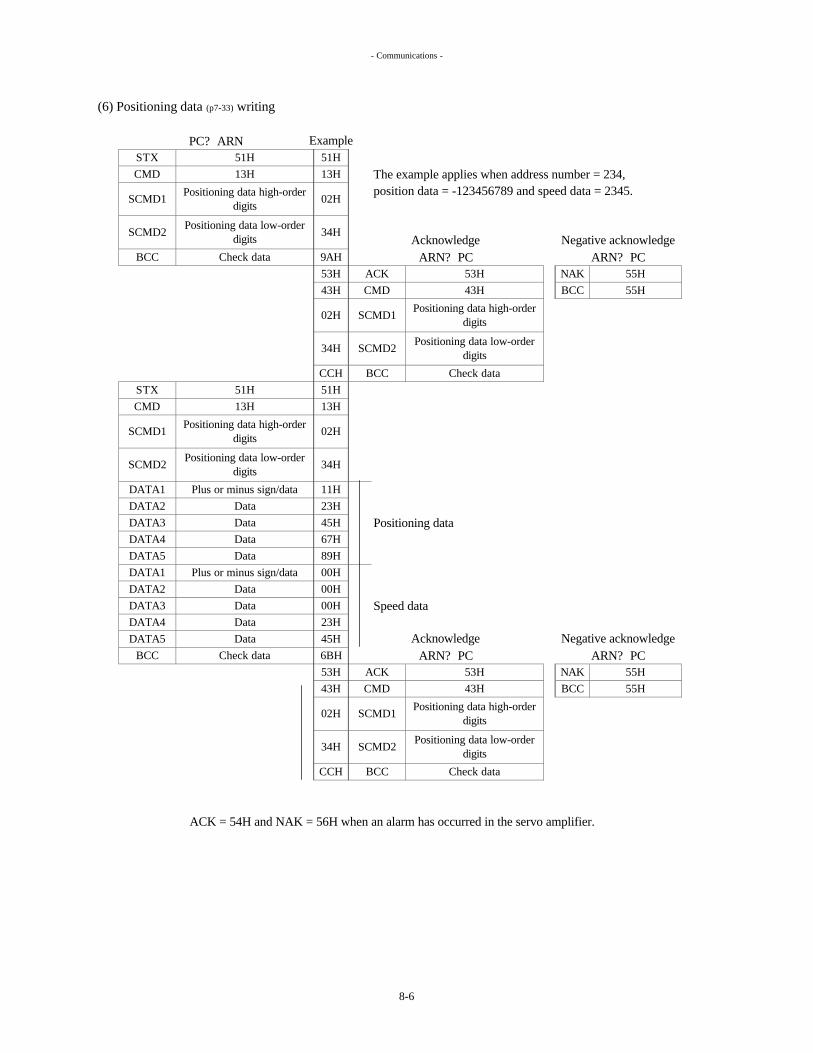
- Communications -
(6) Positioning data (p7-33) writing
The example applies when address number = 234,position data = -123456789 and speed data = 2345.
Positioning data
Speed data
ACK = 54H and NAK = 56H when an alarm has occurred in the servo amplifier.
Positioning data high-order digits
34H SCMD2
02H
34H
CMD 43H
Positioning data low-order digits
SCMD1
02H
34H
02H
SCMD2Positioning data low-order
digits
STX 51HCMD 13H
SCMD1
DATA3 DataDATA4 Data
DATA1 Plus or minus sign/dataDATA2 Data
BCC Check data
51H13H
43H
13H
ACK 53HCMD
Positioning data low-order digits
43H
SCMD1
SCMD2
Positioning data high-order digits
STX 51HCMD 13H
SCMD1Positioning data high-order
digits
SCMD2Positioning data low-order
digits
DataDATA1 Plus or minus sign/dataDATA2 Data
BCC Check dataACK 53H
9AH53H
ARN? PC
BCC Check dataCCH51H
Positioning data high-order digits
BCC Check data
DATA4 DataDATA5 Data
DATA3 Data
DATA5
NAK 55HBCC 55H
67H89H00H
11H23H
CCH
6BH53H43H
02H
34H
ExamplePC? ARN
ARN? PCAcknowledge
Acknowledge
00H00H23H45H
45H
Negative acknowledgeARN? PC
Negative acknowledgeARN? PC
NAK 55HBCC 55H
8-6

- Communications -
(7) Display data (p7-3) reading
The example applies when display data 3 = 123456789.
The alarm history data is as shown below.
Bit no. Low order
Number 0 - 4 correspond to the history numbers on p7-4.0H is the data value when no alarms have occurred.
Example:
DATA1:15H DATA2:02H DATA3:02H DATA4:02H DATA5:01H
4 high order 4 low order
ALHI 0-4 (p7-4) is sent from servo amplifier when display data number is 09H , ALHI 5-9 is sent when display number is 50H.
The data is as shown below when the most recent alarm number is 15, number 4 is 1 and the other numbers are 2.
1 high order 1 low order2 high order 2 low order
0 (latest)high order 0 (latest) low order6 5 4 3
SCMD2DATA1
2 1
Check data
DataData
00H
Plus or minus sign/dataDataData
Display data number
53H84H
NAK 55HBCC 55H
04H
ACKCMD
03H58H53H84H
23H45H67H
SCMD1
BCCSCMD2 Display data number
00H
Check data
ACK = 54H and NAK = 56H when an alarm has occurred in the servo amplifier. DATA5
8 7
DATA4DATA3
SCMD1
BCC
DATA4
00H03H01H
DATA2DATA3
ExamplePC? ARN
AcknowledgeARN? PC
51H04H00H
STXCMD
51H
Negative acknowledgeARN? PC
Byt
e no
.
89H33H
3 high order 3 low orderDATA5
DATA2DATA1
8-7

- Communications -
The digital input monitor (p7-5) data is as shown below. When the input is ON, the data is 1.
Bit no. Low order
The digital output monitor (p7-5) data is as shown below. When the output is ON, the data is 1.
Bit no. Low order BAT ALM cannot be transferred.
Byt
e no
.B
yte
no.
OUT14 OUT15OUT5
OUT11 OUT12DATA4 INPDATA5 OUT8 OUT9 OUT10
OUT1 OUT2OUT13
0 0OUT6 OUT7OUT3 OUT4
0 0 0DATA3 0 0 0 0 0 0
0
CONT13
100
MODE BCONT6CONT14
00
MODE ACONT5
CONT11
300
SVONCONT4CONT12
00
PRDYCONT3
000
CONT2
00
RESET
000
5 4 3 28 1
DATA3 0
CONT9 CONT10DATA4 START
7 6
6 50
DATA1 0
DATA2 0
DATA5 CONT7
DATA18 7
0
0 000 0 0 0
4 2
The data in the software version are: DATA1,2,3 = "0"; DATA4 = Driver CPU; DATA5= Controller CPU.
0
CONT1
00
CONT8
0DATA2
8-8

- Communications -
(8) Initialization (p7-35)
Turn servo ON (p6-9) off when performing initialization using the communication facility.
Perform proper settings in the communication software to avoid any communication timeout.
Initialization for AR10H (p7-35) is invalid by this communication.
<1> Initialization when absolute encoder is used
<2> Initialization when incremental encoder is used
It takes about 30 seconds from when PC sends an initialization instruction to the ARN, to perform initialization, until the ARN returns an acknowledge or a negative acknowledge.
Performing initialization initializes servo parameters, control parameters, and positioning data stored in the servo amplifier, thereby effecting the initial values. It is, therefore, not necessary to turn the power OFF and then back ON.
ACK = 54H and NAK = 56H when an alarm has occurred in the servo amplifier.
Bear in mind that the servo parameters, control parameters and positioning data stored in the servo amplifier will be deleted when initialization is performed.
There are two kinds of initialization: one (ABS) applies when an absolute encoder is used, and the other (INC) applies when an incremental encoder is used. (p7-35)
If initialization is attempted while it is on, it will fail to be performed, and the servo amplifier will return the negative acknowledge (NAK) code.
53H
STX 51HCMD
BCC Check dataSCMD2 00H
BCC 55HSCMD1 01H
CMD 45H
SCMD1
53H NAKACK
01H00H Acknowledge
ARN? PCNegative acknowledge
55H
00H00H98H
15H51H
53H45H
NAK 55HBCC 55H
Check data
Check dataSCMD2 00H
BCC
CMD 45HSCMD1 00H
ACK
STX
SCMD2 00HSCMD1
CMD 15H 15H00H00H66H
99H
53H45H01H00H
PC? ARN
AcknowledgeARN? PC
Negative acknowledgeARN? PC
Data
00H
51H
BCC
51H
ARN? PC
Data
67HCheck data
15H
PC? ARN
01HSCMD2 00H
BCC
8-9

- Alarms -
In addition, the brake (p5-14) is engaged if the servo actuator is equipped with a brake.
Alarms indicated by a black dot ? (serious failures) cannot be released by the reset signal.In this case, turn the power off and then back on.
The BAT ALM (p6-24) battery alarm is not displayed as an alarm.
Ambient temperature is too high.
9. ALARMS
AL-1
AL-2
Overload
Overheating of motor
An overload was detected in the motor by the electronic thermal protector inside the servo amplifier.
When an error has been detected in the servo system, an alarm appears on the 7-segment LED display of the servo amplifier.When an alarm has been detected, the servo actuator turns off the servo system, and the alarm number appears on its front panel 7-segment LED display.
The alarm status can be released either by turning the power off and then back on or by inputting the reset signal (p6-
10) after the cause of the alarm has been removed.
Load is too high, and the motor overheated. Review the selection of the frame
number.
In case of AR10H, OH1 OH2 at CN1 are not connected.(refer to p5-5)
The motor heated up, causing the thermostat inside the motor to trip.
Cool down the servo actuator using a fan.
RemedyDisplay Trouble/symptom criteria
Re-adjust the gain.Hunting. Reduce the inertial load.
If the "AL-17"alarm is displayed, the servo actuator does not turn off the servo system nor is the brake applied.
When the reset signal (p6-10) has been turned on to release the alarm, the requested pulse (p7-3) will have the same value as the feedback pulse.
Parameters can be changed even in the alarm status. An alarm display mode is inserted between the positioning data edit mode and the display mode. (See page 7-1)
The acceleration/deceleration time is too short; the load torque during acceleration/deceleration is too high.
Review the machine system.
Review the selection of the frame number.
Increase the acceleration/deceleration time constant.
Load torque constantly exceeds the rated torque.
"Alarm detection (p6-23)" will turn on when "AL-17" alarm is displayed and will stay on untill current position is between + and -over-travel detection position.
Reduce the ambient temperature.
Check the wiring connections and repair the wiring.
Review the machine system.
CN1 (p5-4) OH1 and OH2 were disconnected between the servo amplifier and servo actuator.
?
Probable cause
9-1

- Alarms -
Turn on the power while the servo actuator is shut down.
Faulty wiring of encoder signal cable between CN1 (p5-4) and servo actuator.
?
Power was turned on while the servo actuator was allowed to rotate.
Connect the cable properly.
Trouble with encoder signals.
Prevent it from being rotated.
Regenerative frequency (p10-11) is too high.
Servo actuator was rotated by an external force.
AL-9
AL-6
AL-7
Low voltage
Internal DC voltage is low.
Reduce the inertial load.
Review the operating pattern.
AL-3 Overheating ofregenerative resistance
The regenerative resistance (p10-11) heated up, causing the thermostat inside the regenerative resistance to trip.
Inertial load is too high.Probable cause RemedyDisplay Trouble/symptom criteria
Acceleration/deceleration time is too short.
Ambient temperature of servo amplifier is too high.
Main power (p5-10,13) is not being input.
Set the input supply voltage to the appropriate level.
Input supply voltage (p5-10,13) is too low.
Reduce the ambient temperature.
Review the selection of the frame number.
Re-adjust the gain (p7-9).Review operating pattern.Re-adjust the gain (p7-9).
Signal cable disconnection
AL-5?
Grounding or short-circuiting of servo actuator's power cable (p5-12,13).
Excessively high load.
Overcurrent
AL-8
Excessively high speed
AL-4 Overvoltage
No short-circuiting between RGEN/DCC (p5-12,13) of TB.
Faulty connection of external regenerative resistance (p5-12).
Internal DC voltage exceeded the allowable limit.
Short-circuit.
Contact us.
Input supply voltage (p5-10,13) is too high.
Normalize the input supply voltage.
Connect the cable properly.
Review the machine system.Output current exceeded the allowable limit.
A power transistor overheated.
Increase the value.
Turn off the signal.
Turn on the main power.
Increase the acceleration/deceleration time constant.
Re-adjust the gain (p7-9).
Excessively high load.
Excessive deviation width (p7-19) value is too low.
Torque limiting enable signal (p6-12) is on.
Excessively highposition deviation
Deviation pulse (p7-3) has exceeded excessive deviation width set in control parameter 25 (p7-19).
Review the machine system.
Output shaft is locked mechanically.Release the lock.
Review the selection of the frame number.
Overshoot of servo actuator.
Hunting in servo actuator.Motor rotation speed has exceeded 3300 rpm (or 2800 rpm for AR135).
9-2

- Alarms -
Brake power supply (p5-14) is not connected.
A servo actuator without a brake is being used but "1" (available) has been selected as the brake available/unavailable CP-7 (p7-15)
setting.
Connect the power supply.
Set to "2" (unavailable).
Brake power is not being supplied.
Faulty wiring of encoder signal cable between CN1 (p5-4) and servo actuator.
Trouble in communication with absolute encoder.
Cross-sectional area of encoder cable is too small.
Correct the encoder cable wiring according to p5-5.
Connect the cable properly.
Encoder cable is too long.
No current is flowing to power cable.
Connect the cable properly.Motor power cable (p5-12,13) has been disconnected.
Motor shaft has rotated more than ±32767 rotations from the origin. (p3-17)
Voltage of the battery (p5-19) used for the absolute encoder has dropped.
Battery is not connected.
Faulty wiring of encoder signal cable between CN1 (p5-4) and servo actuator.
The data stored in the absolute encoder memory has been lost.
The encoder type CP-1 (p7-
13) setting, encoder selector switch (p5-2,3) setting and the actual encoder do not match.
Faulty setting of CP-1: Encoder type (p7-13) or Encoder selector switch (p5-
2,3).
Follow p1-4,5,6,7 to set the parameters and switches to ensure that they match.
AL-12
In the case of an incremental encoder, the origin setting is not necessary.
Perform the origin setting by following the instructions on page 6-7. (The origin setting must be carried out in the current position, since the servo actuator cannot be operated.)
The absolute encoder has exceeded its rotation limit.
Current position has exceeded the limit of the coordinate axes.
Remove the cause and then perform the origin setting by following the instructions on page 6-7. (The origin setting must be carried out in the current position since the servo actuator cannot be operated.)
Display
Encoder type mismatch
Overflow
Encoder trouble
Power cable disconnection
Encoder system down
AL-15
?
?
Remedy
?AL-14
AL-13
Probable cause
Brake power supply disconnection
Trouble/symptom criteria
?
AL-10
AL-11
9-3

- Alarms -
Same as the left.
AL-16
In the equal pitch multi-rotation coordinates (p3-6), the 0 address or addresses exceeding CP- 10 "total number of addresses" have been activated.
AL-17 Soft over-travel detection
The CP-31 soft + over-travel detection position set value is less than the CP-32 soft - over-travel detection position set value.
In either the infinite linear coordinates or the finite linear coordinates mode, positioning with a value more than the limit of the coordinates-- 32767 rotations from the origin-- was instructed.
RemedyAddress error
Display Trouble/symptom criteria Probable cause
Faulty setting of address numbers(p6-11) or positioning data(p7-33).
Specify the address and the positioning data properly.
In the optional division 360°coordinates (p3-7), infinite linear coordinates (p3-8), or finite linear coordinates (p3-9), the 0 address, or the addresses where the motor rotational speed is set to "0", have been activated.
In the optional division 360°coordinates mode, the address of a value less than 0 or equal to or greater than 360 was started.
Specify the CP-31 and CP-32 settings properly.
The current position is farther from the origin than the CP-32 soft - over-travel detection position (p7-20).
The current position is farther from the origin than the CP-31 soft + over-travel detection position (p7-20).
Move the servo actuator to the position between the CP-31 and the CP-32 .
Faulty setting of CP-31 or CP-32.
9-4

- Alarms -
Perform initialization (p7-35).
RemedyTurn power switch ON again.
Display Trouble/symptom criteria Probable cause
AL-19 Position defect Replace a servo actuator.Position memory of absolute encoder has problem.?
| Position ON - Position OFF | > CP-79 (refer to p7-27) Servo actuator is rotated when control
power is off.
Communication problem between CPUs
CPU operation stopped.CPU errorAL-18? CPU problem
Stop the rotation when power off.
Increase the value in CP-79 (p7-27).
Set CP-78 to 2(unvailable) to invalid this alarm.
Remove the cause and then perform the origin setting by following the instructions on page 6-7. (The origin setting must be carried out in the current position since the servo actuator cannot be operated.)
9-5

- General Selection Method -
10-1 General Selection Method
Follow the steps below to select the servo actuator.
(1) Figuring out the load (p10-2)
Decide on the load and operating pattern.
(2) Figuring out the torque area (p10-2)
(3) Figuring out the effective torque (p10-4)
(4) Figuring out the brake torque (p10-5)
(5) Figuring out the reduction gear's service life (p10-5)
(6) Figuring out the positioning accuracy (p10-7)
(7) Figuring out the bearing capacity (p10-8)
(8) Figuring out the moment of inertia of the load (p10-10)
Make sure that the moment of inertia of the load is less than the specification value.
(9) Figuring out the regeneration capacity (p10-11)
10. SELECTION
Make sure that the torque and rotation speed required by the operating pattern are within the torque range of the servo actuator.
Calculate the effective torque from the operating pattern, and check that it is less than the rated torque of the servo actuator.
If the servo actuator is to be held by the brake incorporated inside the servo actuator, check that the brake torque satisfies the requirement.
Make sure that the regenerative power calculated from the operating pattern is within the capacity of the regenerative resistance.
Calculate the anticipated service life of the reduction gear from the operating pattern, and check that it is more than the required service life.
Make sure that the backlash, lost motion, angle transmission error and spring constant satisfy the requirements.
Make sure that the thrust weight and moment applied to the main bearing of the servo actuator are less than the specification values.
When the servo actuator decelerates, the inertial energy is converted into heat by the regenerative resistance inside the servo amplifier.
10-1

- Details of Selection Methods -
10-2 Details of Selection Methods
(1) Figuring out the load
Operating patternT1 : Acceleration torque [N•m]T2 : Torque in steady state [N•m]T3 : Torque at shutdown [N•m]T4 : Torque during deceleration [N•m]
N1 : Maximum rotation speed [rpm]t1 : Acceleration/deceleration time [sec]t2 : Steady-state operation time [sec]t3 : Shutdown time [sec]
t1 t2 t1 t3 Time
(2) Figuring out the torque area
The maximum torque ranges of the servo actuators are provided below.
Maximum torque [N•m] Maximum torque [N•m]
0 0
"i" = in the graph, indicates the reduction gear ratio.
Rotation speed [rpm] Rotation speed [rpm]40 6020
Decide on the operating pattern from the load conditions, and plot the load torque versus time and output rotation speed versus time as graphs.
Make sure that the torque and rotation speed required by the operating pattern are within the maximum torque range of the servo actuator.
AR30
1000
AR15
Decide on the operating pattern.
Out
put r
otat
ion
spee
d
T1
T2
T3
100
200
500
Loa
d to
rque
T4
N1
0
40 6020
i= 56
i= 80
i= 104
i= 120
i= 120
i= 104
i= 80
i= 56
i=140
i= 152
10-2

- Details of Selection Methods -
Maximum torque [N•m] Maximum torque [N•m]
0 0
Maximum torque [N•m] Maximum torque [N•m]
0
0
Maximum torque [N•m] Maximum torque [N•m]
0
"i" = in the graph, indicates the reduction gear ratio.
Make sure that the operating pattern is within themaximum torque range of the servo actuator.
ARH24
Rotation speed [rpm] Rotation speed [rpm]
Rotation speed [rpm]
200 300
300
AR10H
400
100
ARH7 ARH17
AR60
2000
20001000
AR135
Rotation speed [rpm] Rotation speed [rpm]10
4000
20 30
200
100
800
400
200
300100 200
200100Rotation speed [rpm]
10 20 4030
i= 153/5
i= 21
i= 461/41
i= 120
i=152
i=100
i=80 i=80i=100
i=128i=170
i=21
i=11
i= 31
i=21
i=11
i= 31
i=65 80
i=144
10-3

- Details of Selection Methods -
(3) Figuring out the effective torque
Operating pattern T1 : Acceleration torque [N•m]T2 : Torque in steady state [N•m]T3 : Torque at shutdown [N•m]T4 : Torque during deceleration [N•m]
N1 : Maximum rotation speed [rpm]t1 : Acceleration/deceleration time [sec]t2 : Steady-state operation time [sec]t3 : Shutdown time [sec]
t1 t2 t1 t3 Time
The rated torques of the servo actuators are shown below.
129 145 171
17080 100 120 152 80 100 128 144
Calculate the anticipated effective torque from the operating pattern, and check that it is less than the rated torque of the servo actuator.
Reduction gear ratio A, B type
Reduction gear ratio C type
17
140
141
167
56 120
121
[N•m] t1×T12 + t2×T22 + t3×T32 + t1×T42
2×t1 + t2 + t3
Make sure that the effective torque is less than the rated torque of the servo actuator.
Frame numberReduction gear ratio
Rated torque
3149
2.6
80 104
Frame number
Reduction gear ratio A, B type
65
14114
105
24525
AR15
56
57
132
57
81
-
31 2111
101 121 153 81 101-
N•mkgf•m
81
1881913
376 470 564
N1
Reduction gear ratio C type
Rated torque
28229
Effective torque Trms =
Loa
d to
rque
Out
put r
otat
ion
spee
d
T2
T3
0
T4
941
ARH1711
ARH24
753715
ARH7
12 37
66
304 1204 1352 1599
AR10H
31
461/41 153/521
5.026 73
7.4198 292
58 73 96 123 138
21
15 11146 10352 99
5.3 10
48 77
Frame number
Rated torque
AR30
152
153
363666.7
N•mkgf•m
Unit
163
AR135
949.6
122
38
AR60
The effective torque is calculated using the following formula for the operating patterns presented below.
Unit
-
-
80
81
104
105
120
121
Make sure that the servolock torque is 70% or less than the rated torque of the servo actuator.
Unit-
N•mkgf•m
4572720 30
10-4

- Details of Selection Methods -
(4) Figuring out the brake torque
The brake torques of the servo actuators are shown below.
(5) Figuring out the reduction gear's service life
How to calculate the service life of the reduction gear is provided for the operating pattern below.
Operating patternT1 : Acceleration torque [N•m]T2 : Torque in steady state [N•m]T3 : Torque at shutdown [N•m]T4 : Torque during deceleration [N•m]
N1 : Maximum rotation speed [rpm]t1 : Acceleration/deceleration time [sec]t2 : Steady-state operation time [sec]t3 : Shutdown time [sec]
t1 t2 t1 t3 Time
32 478.3 16 23 17314 461
ARH24312111
184962
81 157 22521
ARH17
657 774
167
81
55 67 79 98 107 131
22
121 153
Frame number
56
400282115
80 104 12081 105
Unit
Out
put r
otat
ion
spee
dL
oad
torq
ue
11-
T1
126.1 9.1
T3
153
Reduction gear ratio C type -
Brake torqueN•m
kgf•m539
57
3629212
6566
86 162143
101
8.8
57
80
80
14480 100
353
10456
41
31N•m
kgf•m60 89 119
0
Frame number
Calculate the anticipated service life of the reduction gear from the operating pattern, and check that it is more than the required service life.
Make sure that the brake torque of the servo actuator is higher than the brake torque requirement.
AR10H45
24525
461/41
T2
- 128
N1
153/5
T4
Brake torque
Reduction gear ratio 21
81
AR15
14118619
105 121
12 15 17
1712109215
1286 1615101 129
1803145
165
49450
811051
AR60 AR135170100 120 152
If the servo actuator is to be held by the brake (p5-14) incorporated inside the servo actuator, check that the brake torque satisfies the requirement.
Unit--
Frame number AR30140 152120
121
ARH7
N•mkgf•m
Reduction gear ratio A, B typeReduction gear ratio C type
Brake torque
45146
UnitReduction gear ratio A, B type
10-5

- Details of Selection Methods -
Calculate the mean load torque (Tm).
10/3
Tm = [N•m]
Torque at shutdown (T3) and shutdown time (t3) are not used in this calculation.
Calculate the mean output rotation speed (Nm).
T0 :
N0 :
Calculate the service life of the reduction gear in years (Ly).(Rotation shutdown time t3 and the annual operation rate are factored into this calculation.)
d : Annual operation rate [%]
The table below shows the torque and rotation speed ratings of the reduction gears.
17
ARH768.6412137
ARH24ARH17167 235
AR1351568
N0
Nm[hour])(
T0
50
[rpm]
AR15 AR30 AR60
10/3
(2×t1 + t2)× ×24×365Lh×(2×t1 + t2 + t3)×100
2×t1 + t2
×
t1×(N1/2)×T110/3 + t2×N1×T210/3 + t1×(N1/2)×T410/3
2×t1×(N1/2) + t2×N1
Calculate the service life of the reduction gear in hours (Lh). (Rotation shutdown time t3 is not factored into this calculation.)
Rated torque [N•m] of reduction gear
2×t1×(N1/2) + t2×N1Nm =
Lh = 6000Tm
×
Ly =
42
The rated rotation speed resulting from the calculation of the reduction gear's service life differs from the rated output rotation speed of the servo actuator (p2-2).
Rated rotation speed [rpm] of reduction gear
Rated torque T0
Frame numberN•m
[year]
Unit784
Make sure that the service life of the reduction gear is longer than the required service life.
24160 7rpm 15
80kgf• 14Rated rotation speed N0
AR10H981015
10-6

- Details of Selection Methods -
(6) Figuring out the positioning accuracy
Calculate the backlash, lost motion, angle transmission error and spring constant as shown below.
The hysteresis curve shown in the figure below expresses this correspondence.The spring constant, lost motion and backlash are defined in the figure below.
Torque
-100% 100%
Lost motion :
Backlash : Twist angle at "zero" torque of hysteresis curve [arc min]
Twist amount = L × tan (twist angle [arc min]/60) [mm]
The table below shows the spring constants, lost motion and backlash of the servo actuators.
6
AR10H474.811
AR15 AR30
arc min
3.534
Spring constant
Lost motionBacklash 1
[arc min]
ARH24444.5
108ARH17
293.0
Twist angle =Load torque [N•m]
Spring constant [N•m/arc min]Lost motion [arc min]
2+
arc min 611 40
1kgf• /arc min 1.520
ba
=
N•m/arc minAR60196 392
ARH715
AR135
Make sure that the backlash, lost motion, angle transmission error and spring constant satisfy the requirements.
The following formula is used to calculate the twist angle and twisting amount when the load torque (offset load, etc.) is applied to the servo actuator from one direction.
The total twist angle when the load is applied in one direction and also in its opposite direction is the value obtained by adding the backlash amount to twice the value calculated using the formula above.
L : Distance from rotary center of servo actuator to load point [mm]
Rated torque/2Twist angle at rated torque - Twist angle at 50% of rated torque
Twist angle at intermediate point of hysteresis curve width at ±3% of rated torque. [arc min]
When the input shaft of the servo actuator (servo motor shaft) is secured and torque is applied to the output shaft side, twisting corresponding to the torque applied is generated.
Spring constant = [N•m/arc min]
Lost motion
a
±3% rate torque
Backlash Twist angle
Rated torque Rated torque
b
50%
10-7

- Details of Selection Methods -
The definition and specification of the angle transmission error are provided below.
?in : Input angle [arc min]?out : Output angle [arc min]
i : Reduction gear ratio [-]
The angle transmission error (? er) of the AR series is not more than 1 arc min.
(7) Figuring out the bearing capacity
Make sure that the thrust weight and moment applied to the main bearing of the servo actuator are less than the specification values.
The "thrust weight" refers to the weight which is applied in the direction shown in the figure below, and its specification is shown in the table on the right.
Frame numberAllowable thrust weight
kgfAR15
N
1500ARH7 1501470
AR30200530
AR135 14700
51941960
AR60 7840 800
The "angle transmission error" is the difference between the theoretical output rotation angle when any rotation angle (?in) is supplied to the servo actuator and the actual output rotation angle (?out).
Angle transmission error (?er) =? in
Make sure that the positioning accuracy of the servoactuator satisfies the positioning accuracy requirement.
i- ? out [arc min]
This accuracy is expressed in terms of angle transmission error (?er).
(The angle transmission error of the ARH**F and ARH**S does not stipulate to any particular value.)
Make sure that the thrust weight is less than the value allowed for the servo actuator.
200300
19602940
ARH17ARH24AR10H 5880 600
Angle transmissionerror specification
Ang
le tr
ansm
issi
on e
rror
1 rotation of output shaft
[arc sec]
10-8

- Details of Selection Methods -
The "moment" refers to the weight which is applied in the direction shown in the figure below.
The moment is calculated as follows.
A, B type : Moment [N•m] = W1×(L1-a)+W2×L2
C, F, S type, AR10H : Moment [N•m] = W1×(L1-b)+W2×L2
W1, W2 : Weight [N] from loadL1,L2 : Distance [m] up to weight action pointa,b : Constants [m]
The table below shows the allowable moment and constants a and b of the servo actuators.
AR10H
Make sure that the load moment is less than the allowable moment of the servo actuator.
- 0.030843 860.017
ARH24686 70 -
Frame number
AR15AR30AR60
-
0.057
608 621666
0.025- 0.031
461 47804 82
-0.0020.071 -0.011
0.052 0.011170
a b m
0.042 0.005
ARH17
Allowable momentN•m kgf•m
AR135ARH7
1735 1773920 400
10-9

- Details of Selection Methods -
(8) Figuring out the moment of inertia of the load
The table below shows the servo actuators' allowable moments of inertia of the load.
1 14 2
Example : Calculation for the Load which diameter = D[m], weight = W[kg] and circular shape is shown below.
Moment of inertia of the load [kg m2 (GD2/4)]= W[kg] D2[m]
38
Make sure that the moment of inertia of the load is less than the specification value of the servo actuator.
AR10H45
9.65.3 12 5.0 170.59 2.2 4.7 1.5
Allowable moment of inertia of load
kg•m2
(GD2/4)
Allowable moment of inertia of load
kg•m2
(GD2/4)
120
Reduction gear ratio A, B type
-
Reduction gear ratio C type
-
31Frame number
Reduction gear ratio 21ARH17
11461/41
71
51 77
101 12166 81
AR135
153
173
Make sure that the moment of inertia of the load is lessthan the specification value of the servo actuator.
Unit- 21 153/5 11
ARH24ARH721 31
kg•m2
(GD2/4)
Frame number
Reduction gear ratio A, B type
Reduction gear ratio C type
Allowable moment of inertia of load
AR30
113
Frame number Unit
153
Unit
-
-
AR15
104 120 152
65 128 144
AR60
10080 120 152 170
56 80 104 120 140 56 80
80 100
81 101 129 145 171
57 81 105 121 141 57 81 105 121
1142
5.2 11 18 24 32 15 31 53
277 819253 395 647
10-10

- Details of Selection Methods -
(9) Figuring out the regeneration capacity
Operating patternT1 : Acceleration torque [N•m]T2 : Torque in steady state [N•m]T3 : Torque at shutdown [N•m]T4 : Torque during deceleration [N•m]
N1 : Maximum rotation speed [rpm]t1 : Acceleration/deceleration time [sec]t2 : Steady-state operation time [sec]t3 : Shutdown time [sec]
t1 t2 t1 t3 Time
T4×(N1/2)×0.105×t1Regenerative power [W] =
2×t1 + t2 + t3
When the servo actuator decelerates, the inertial energy is converted into heat by the regenerative resistance inside the servo amplifier.
Make sure that the regenerative power calculated from the operating pattern is within the capacity of the regenerative resistance.
When the inertial load has been positioned in the above operating pattern, the shaded area represents the regeneration range.The method used to calculate the regenerative power and the allowable values for the servo amplifier are shown below.
Loa
d to
rque
Out
put r
otat
ion
spee
d
N1
T1
T2
ARN30
T3
T4
0
Allowable regenerative power [W]
Make sure that the regenerative power is lessthan the allowable value of the servo amplifier.
Servo amplifierframe number
20
ARN135ARN60
ARN15206060
10-11

- External Dimensions -
11-1 Servo Actuator
11. EXTERNAL DIMENSIONS
11-1
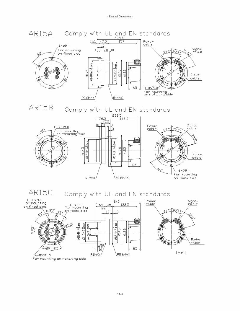
- External Dimensions -
11-2

- External Dimensions -
11-3

- External Dimensions -
11-4

- External Dimensions -
11-5
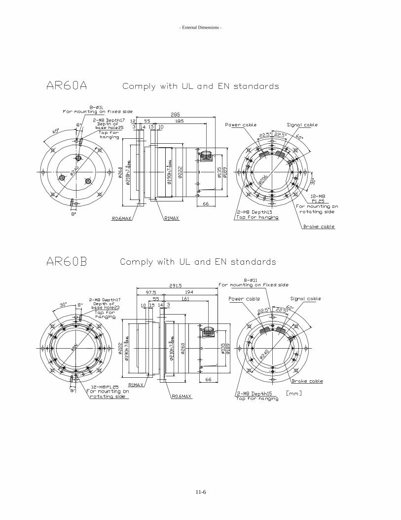
- External Dimensions -
11-6

- External Dimensions -
11-7

- External Dimensions -
11-8

- External Dimensions -
11-9

- External Dimensions -
11-10

- External Dimensions -
11-11

- External Dimensions -
11-12

- External Dimensions -
11-13
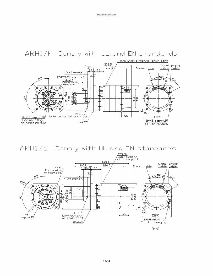
- External Dimensions -
11-14

- External Dimensions -
11-15

- External Dimensions -
11-16

- External Dimensions -
11-17

- External Dimensions -
11-2 Servo Amplifier
(1) ARN15, 30
11-18

- External Dimensions -
(2) ARN60, 135
11-19

Product disposal
To protect the environment, choose a recycling contractor, if possible, whendisposing of the servo system.
If you have any questions concerning the disposal of servo system, consult withthe dealership where you purchased the product or contact our sales office.
Service information
When you have any questions concerning the servo system or servicing, pleasecontact us at any of the following addresses.
When you request service, please inform us of the basic information (model andserial numbers) on your servo system's nameplate.
Nabtesco Precision USA Inc31731 Northwestern Hwy.,Suite 113E, Farmington Hills,Michigan 48334 U.S.A.Phone : +1-248-538-9165 Fax : +1-248-538-9170Email : [email protected] page : www.nabtesco-precision.com
In Europe and AfricaNabtesco Precision Europe GmbHKlosterstrße 49, D-40211 Düsseldorf Germany Phone : +49-211-17379-0 Fax : +49-211-364677Email : [email protected] page : www.nabtesco-precision.de
In Asia and othersTokyo Head Office1-9-18 Kaigan,Minato-ku, Tokyo 105-0022,JapanPhone : +81-3-3578-7461 Fax : +81-3-3578-7471Email : [email protected] page : www.ts-corporasion.co.jp
Tsu Plant (Engineering Department)594,Ichimachida,Katada-cho,Tsu-shi,Mie-Pref. 514-8533,JapanPhone : +81-59-237-4602 Fax : +81-59-237-4612
The contents of this instruction manual are subject to change without prior notice.