
BARTELSbartels.eu/fileadmin/bartels/templates/downloads/Catalog_furling... · What is so special...
64
Sailing. Furling. BARTELS. Headsail Furling and Reefing Systems Catalogue and Guideline 12/13 BARTELS
Transcript of BARTELSbartels.eu/fileadmin/bartels/templates/downloads/Catalog_furling... · What is so special...

Sailing. Furling. BARTELS.
HeadsailFurling and Reefing SystemsCatalogue and Guideline
12/13
BARTELS

Introduction
All our systems and parts are guaranteed for fiveyears*.
We offer an almost unlimited combination ofoptions within our program, also with existingsystems and other external components.
We hope you enjoy reading our catalog. It con-tains details and information to help you in theselection of the components. Our complete pro-gram makes it easy for you to assemble theneeded parts list yourself, or get some freeadvice from us. Our experienced technicians willalso gladly create a customized proposal foryour individual solution.
* Except for natural wear and tear (like withlines, GENNEX tubing).
Please note:We always adapt our parts to the newest technical standards. Therefore we are forced to reserve all rights regarding changes in shapeand technique. The features of the indications, illustrations and descriptions in this catalogue and guide are not be regarded as a bind-ing agreement. Thus any legal claims or rights in this respect are excluded.
Attention! Improper structural alterations on the boat can lead to damage or even to loss of seaworthiness. In case you do not have the suitabletools and equipment or sufficient specific technical knowledge, please allow us or another special workshop to perform the assembly oralterations on your boat.
© Not to be reprinted, translated or otherwise reproduced in whole or in part without written permission. The right to modify the techni-cal detail given in the data and illustrations of this catalogue and manual is reserved.
Dear sailing friends,
Making sailing as comfortable as possible is ourambition.Even if the weather conditions are difficult, wewant to help you with our sophisticated and reli-able technology. But also under normal condi-tions, we would like to offer you the utmost com-fort.Our jib furling and reefing systems are designedfor all sailors who demand quality products, whomade the right decision for good products and asolid workmanship.
What is so special about BARTELS?
Quality, individuality and service are our highestprinciples.
We offer solutions for almost every application,from the flying topgenoa to roller furling systemswith foil headstay including angularly movablewatertight deck passage. We use stainless andsalt water resistant materials exclusively.
Our components and systems were all testedunder harshest conditions and are designed forlongevity.
BARTELS

Content
Systems overview 02 - 03
Variants of furling systems in detail 04 – 25Furling systems for flying sails 04 - 07Headsail furling systems with tackle for sails with hanks 08 - 09Headsail furling systems with halyard swivel for wire headstay and sails with hanks 10 - 13Headsail reefing systems for headstay Ø up to 7mm 14 - 17Headsail reefing systems for headstay Ø from 7mm 18 - 23Awning systems – SunFurl 24 - 25
Components in detail 26 - 58Jib furler Classic 26Jib furler Endless 27Jib furler S-Series (headstay from 7mm, non rotating) 28 - 29Jib furler Code 0 and Gennex Systems 30 - 33Deck passage Classic (watertight) 34Thread connector 35Deck passage S-Series (watertight) 36 - 37Telescope coupling set 38Three and four hole plates 39Halyard swivel for foil 40Foil 41Halyard swivel for wire headstay 42Coupling terminal 43Headstay swivel 44Swivel with cable sheave 45Connections between topswivel and mast 46Halyard guiding 47Accessories for flying sail furling systems 48 - 49Halyard swivel 50Halyard guidance 52 - 53Wire/ Rod processing (swaging and cold heading) 54 - 55Ropes and rope guidance 56Guide rollers 57Installation hints for rope guidance 58 - 59General business terms 60
01

Furling system forflying sails
A
For rein-forced luff -
Code 0A1
For gen-naker -
GENNEXA2
Headsail furlingsystems with tacklefor sails with hanks
B
With rotat-ing
forestayB1
Headsail furlingsystems with hal-
yard swivel for wire headstay and sails
with hanks
C
With rotat-ing
forestayC1
Headsail reefingsystems
D
For head-stay Ø up
to 7mmD1
For head-stay Ø
from 7mmD2
02
D 1 - 1 1 1 - 1
Furling system (A/ B/ C/ D)Variant
Material (1 stainless steel, 2 aluminium)Installation (1 on deck, 2 below deck)
Type of furler (1 drum, 2 endless, 3 electric)
Size
System overview
A
B
C
D

Installation on deck Installation below deck
Stainless steel Aluminium Stainless steel
Drum Endless Endless Drum Endless Electric
111 112 122 211 212 213
Page 04 - 05 Without refference in the catalogue(please ask for further information)
Page 06 - 07
Page 08 - 09
Page 10 - 11 Page 12 - 13
Page 14 - 15 Page 16 - 17
Page 18 - 19 Page 20 - 21 Page 22 - 23
03

Furling system for flyingsails
Code 0 (installation on deck)
04
A1-1
12A1
-122
Scope of application:
Depending on the type of luff reinforcement ofan existing top genoa or for new builds, Bartelsoffers jib furlers with continuously looping line intwo ranges of manufacture - Jib Furler Endless(stainless steel) and Jib Furler Competition (alu-minum).Both series can also be retrofitted to GENNEXsystems0 and can then be used both for Code 0and gennaker.The continuous loop line is removable and canbe left on deck when the jib furler is to beunbend together with the sail, for example ontoand off an outrigger boom / bowsprit.
Benefits code 0 stainless steel:l Sturdy stainless steel constructionl Narrow fork width for shakles or platesl Fastening of the triangular plates of top
genoas with reinforced luff by two wires and webbing
Headsail area [m²]
Configuration
Main components Accessories Code 0 stainless steel Accessories Code 0 competition
Jib furler Headstay swivel Triangle
plateSnap shackle with lap-
pet Thimble shnap shackle withfork
≤ 30 A1-112-1 FE I FAW I 18/12 5879-1 -- --
≤ 50A1-112-2 FE II FAW II 18/13 5879-2 -- --A1-122-2 FE II-L FAW II-L -- -- 42/111 5979-6
≤ 70A1-112-3 FE III FAW III 18/14-6 5898-3 -- --A1-122-3 FE III-L FAW III-L -- -- 42/114 5998-6
≤ 100A1-112-4 FE IV FAW IV 18/14-8 5899-4 -- --A1-122-4 FE IV-L FAW IV-L -- -- 42/116 5999-6
Benefits Code 0 Competition:l Aluminum lightweight constructionl Wide fork width for direct termination of anti
torsion rope with spliced-in thimblesl Captive quick release pins for easy bending
and unbending of the saill Lower weight l Swivel with shock and scratch protection

05
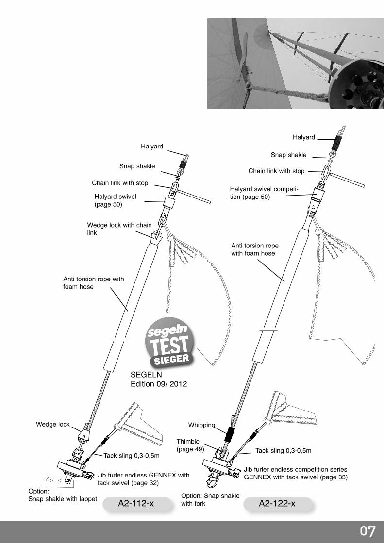
A1-112-x A1-122-x
Halyard swivel competitionseries (page 50)
Thimble(page 49)
Anti torsion rope
Snap shackle
Halyard
Thimble(page 49)
Jib furler endless competitionseries - Code 0 (page 31)
Jib furler endlessCode 0 (page 30)
Option:snap shackle with fork(page 49)
Option:snap shackle with lap-pet (page 48)
Triangle plate(page 48)
Luff reinforced withwebbing and twowires
Triangle plate(page 39)
Halyard swivel classic series withchain link (page 50) Snap Shackle
Halyard

06
Headsail area [m²]
Anti torsionrope length
(m)Configuration
Main components AccessoriesGennex stainless steel
AccessoriesGennex competition series
Jib furler Headstayswivel Snap shakle with lappet Snap shakle with fork
≤ 50 ≤ 9 A2-112-1 FE I FAW I 5879-1 --
≤ 70 ≤ 12A2-112-2 FE II FAW II 5879-2 --A2-122-2 FE II-L FAW II-L -- 5979-6
≤ 150 ≤ 15A2-112-3 FE III FAW III 5898-3 --A2-122-3 FE III-L FAW III-L -- 5998-6
≤ 200 ≤ 20A2-112-4 FE IV FAW IV 5899-4 --A2-122-4 FE IV-L FAW IV-L -- 5999-6
Furling system for flying sails
GENNEX (installation ondeck)
Scope of application:
Gennex systems are used for furling flying gen-nakers with curved luffs. Especially advanta-geous is the hoisting and lowering of the sail ina rolled state, which simplifies the handling oflarge sails with a small crew
Unlike with top genoas, the luff needs not to bereinforced since the curvature of the luff can befreely adjusted depending on the cut, andbecause the furling process around a anti tor-sion line starts from above. The tack is fixed toa separate tack swivel and thus is rolled up last.
For the furling process the anti torsion ropeabsolutely must be under high tension, there-fore its length is to be measured under load andalways in such a way so the halyard shakledoes not hit the sheave box on the mast.
Bartels offers two versions: Classic in stainlesssteel and Competition in lightweight aluminumconstruction. Both Gennex jib furling systemscan be used for gennaker and Code 0. The topgenoa is bent on instead of the anti torsion ropeand the tack swivel stays without function.
The continuous loop line is removable and canbe left on deck when the jib furler is to beunbend together with the sail, for example ontoand off an outrigger boom / bowsprit.
Benefits, Gennex stainless steel:l Stainless steel constructionl Narrow fork width for attaching the anti tor
sion rope via a wedge lockl The exact length can be easily adjusted on-
site at the lower wedge lockl When used as Code 0 furler system, top
genoas can be attached by means of trian- gular plates
Benefits GENNEX Competition:l Aluminum lightweight constructionl Wide fork width for direct bending-on of a
anti torsion rope with spliced-in thimblesl Captive quick release pins for easy bending
and unbending of the saill Lower weightl Swivel with shock and scratch protection
A2-1
12A2
-122
07
A2-112-x A2-122-x
Anti torsion ropewith foam hose
Anti torsion rope withfoam hose
Wedge lock with chainlink
Whipping
Jib furler endless competition seriesGENNEX with tack swivel (page 33)
Tack sling 0,3-0,5m
Thimble(page 49)
Halyard
Snap shakle
Chain link with stopHalyard swivel competi-tion (page 50)Halyard swivel
(page 50)
Halyard
Snap shakle
Chain link with stop
Jib furler endless GENNEX withtack swivel (page 32)
Tack sling 0,3-0,5m
Wedge lock
SEGELNEdition 09/ 2012
Option: Snap shaklewith fork
Option:Snap shakle with lappet

08
Headsail furling systems withtackle for sails with hanks
Installation on deck
Headsailarea [m²]
Displace-ment
[t]
HeadstayØ
[mm]
Headstaylength
[m] Configuration
Main components
Jib furler Headstay swivel Four hole plate Tackle
≤ 15 ≤ 1,5 4 7 - 9B1-111-1 F I
WS I 17/2 T2FB1-112-1 FE I
≤ 25 1,5 - 2,5 4 - 5 8 - 11B1-111-2 F II
WS II 17/4 T3FB1-112-2 FE II
≤ 35 2,5 - 3,5 5 - 6 9 - 11B1-111-3 F III
WS III 17/5 T4-FB1-112-3 FE III
≤ 50 3,5 - 6 6 - 8 9 - 12B1-111-4 F IV
WS IV 17/6 T-MB1-112-4 FE IV
Scope of application:
The jib furling system with tackle is characte-rized by its simple design. The cable halyard isrunning around a block in the swivel and tight-ened above the jib furler with a tackle.
The separate halyard (parallel to the headstay)is operated from the forepeak. When changingthe sail, the cable halyard must be extendedwith a safety line, so it does not run out. Sailswith shorter luff must be extended with a cablelead to make sure the tackle reaches far enough(for example when using a storm jib).
This Type furler is most commonly used withheadsails which are rarely changed (jib or cutterforestays).
Benefits:l Simple, cost-effective systeml Easy installation and handlingl Continued use of hank-on sailsl Simple upgrading to a jib furling system
with halyard swivel for cable forestaysB1
-111
B1-1
12

09
B1-111-x B1-112-x
Wire halyard (parallel tothe forestay)
Tackle for hauling tight thehalyard (page 56)
Four hole plate for the con-nection of forestay, tackle andsail tack (page 39)
Headstay swivel withsheave (page 45)
Lappet/ fork/ T-tog-gle (page 46)
Jib furler classic(page 26)
Chain plate
Jib furler endless(page 27)
Chain plate
Foto
: Skib
ladnir
Stopper bullet
Headstay
Hank
Snap shakle
Snap shaklel
Tackle for hauling tight thehalyard (page 56)
Four hole plate for the con-nection of forestay, tackle andsail tack (page 39)
Snap shakle

10
Furling system with halyardswivel for wire forestay andsails with hanks
Installation on deck
Scope of application:
The jib furling systems with halyard swivel forcable forestays are suitable for complete furlingof hank-on sails. A Reefing is not possiblebecause the cable forestay is not suitable as areefing core (the sail is constricted, twisted anddamaged). This type of system is often used for classicyachts, if possible, usually below deck to pre-serve the classic appearance with modern tech-nology (pages 12-13).Beyond headstay lengths of 8 to 9 meters werecommend using a halyard swivel with couplingand a coupling terminal (see page 43 fordetails). In the top position, the halyard swivelengages into the longitudinal groove of the cou-pling terminal. Thus the sail head is rotated andblowing out of the furled sail in the head area isprevented during stronger wind gusts.
The length of the luff must be adjusted so thatthe halyard swivel is positioned at about themiddle of the coupling terminal. Sails with ashorter luff must be extended with a cableextension.
Benefits:l Continued use of hank-on sailsl Maintaining the appearance of classic yachts
(especially when installed below deck)l Continued use of existing jib halyardl Safe sail changes (during a sail change, the
halyard always stays connected to the headstay by the sliding halyard swivel)
Headsailarea [m²]
Displace-ment
[t]HeadstayØ
[mm]Headstay
length [m]
ConfigurationMain components
Jib furler Halyard swivel
Coupling terminal
Headstayswivel Three hole plate
≤ 15 ≤ 1,5 4 7 - 9C1-111-1 F I
FS I not requiredSTW I
18/6C1-112-1 FE I
18/9≤ 25 ≤ 2,5
4 - 5 ≤ 8C1-111-2 F II
STW II-5C1-112-2 FE II
5 8 - 12C2-111-2 F II
FS II-DK 37/39-5 VSTC2-112-2 FE II
≤ 35 2,5 - 3,5 5 - 6≤ 9
C1-111-3 F IIIFS II-D-6 not required STW II-5
STW II-6STW III
18/10-IIC1-112-3 FE III
9 - 13C2-111-3 F III
FS II-DK 37/39-5 VST37/39-6 VSTC2-112-3 FE III
≤ 50 3,5 - 6 7 - 8 9 - 15C2-111-4 F IV
FS III-DK 37/43-7 VST37/43-8 VST STW IV 18/10-III
C2-112-4 FE IV
C1-1
11C1
-112

11
C1-111-x C1-112-x
Halyard swivel for wireheadstay (page 42)
Headstay swivel (page 44)
Lappet/ fork/ T-tog-gle (page 46)
Jib furler classic(page 26)
Jib furler endless(page 27)
Stopper bullet
Headstay
Hank
Snap shackle
Snap shackle
Halyard
Halyard lead eye(page 47 + 52)
Three hole plate(page 39)
Turnbuckle
Chain plate Chain plate
Three hole plate(page 39)
Turnbuckle
Coupling terminal(details on page 43)
Halyyard swivel withcoupling(details on page 42)
Headstay
Coupling terminal required for head-stay length exceeding 8m.

12
Furling system with halyardswivel for wire headstay andsails with hanks
Installation below deck
Scope of application:
This type of system with waterproof deck pas-sage is used on classic yachts to preserve thelook even with modern technology. In competi-tion sailing too, the installation of a jib furler sys-tem below deck makes it possible to shackle thesail's tack close to the deck, as long as the classrules permit jib furling systems. The jib furlingsystems with sliding halyard swivel for cableforestays are suitable for the complete furling upof a hank-on headsail. Reefing is not possiblebecause the cable forestay is not suitable asfurling core (the sail is constricted, twisted anddamaged). Beyond forestay lengths of 8 to 9meters we recommend using a halyard swivelwith coupling and a coupling terminal (see page43 for details). In the top position, the halyardswivel engages into the longitudinal groove ofthe coupling terminal. Thus the sail head is rota-ted and blowing out of the furled sail in the headarea is prevented during stronger wind gusts.
The length of the luff must be adjusted so thatthe sliding halyard swivel sits at about the mid-dle of the coupling terminal. Sails with a shorterluff must be extended with a cable extension.
Benefits:l Continued use of hank-on sailsl Maintaining the appearance of classic yachtsl Continued use of existing jib halyardl Safe sail changes (the halyard always
remains attached to the forestay via the slid-ing halyard swivel)
Headsailarea [m²]
Displacement
[t]
HeadstayØ
[mm]
Headstaylength
[m]Configuration
Main components
Jib furler Deck passage
Halyard swivel
Coupling terminal
Headstayswivel
Three holeplate
≤ 15 < 1,5 4 7 - 9C1-211-1 F I-2
DD IFS I not required
STW I18/6
C1-212-1 FE I-2
18/9≤ 25 < 2,5 4 - 5
< 8C1-211-2 F II-2
STW II-5C1-212-2 FE II-2
8 - 12C2-211-2 F II-2
FS II-DK 37/39-5 VSTC2-212-2 FE II-2
≤ 35 2,5 - 3,5 5 - 6< 9
C1-211-3 F III-2
DD IIFS II-D-6 not required STW II-5
STW II-6STW III
18/10-IIC1-212-3 FE III-2
9 - 13C2-211-3 F III-2
FS II-DK 7/39-5 VST37/39-6 VSTC2-212-3 FE III-2
≤ 50 3,5 - 6 7 - 8 9 - 15C2-211-4 F IV-2
DD III FS III-DK 37/43-7 VST37/43-8 VST STW IV 18/10-III
C2-212-4 FE IV-2
C1-2
11C1
-212

13
C1-212-xC1-211-x
Foto
: www
.lacu
stre.
ch /
Kauf
man
nHalyard swivel for wireforestay(page 42)
Headstay swivel (page 44)
Lappet/ fork/ T-tog-gle (page 46)
Jib furler classic(page 26)
Jib furler endless(page 27)
Stopper bullet
Headstay
Hank
Snap shakle
snap shakle
Halyard
Three hole plate(page 39)
Turnbuckle
Chain plate Chain plate
Three hole plate(page 39)
Safety turnbuckle(on request)
Safety turnbuckle(on request)
Turnbuckle
Coupling terminal(details on page 43)
Halyard swivel withcoupling(details on page 42)
Headstay
Halyard lead eye(page 47 + 52)
Coupling terminal required for head-stay length exceeding 8m.

14
Headsail reefing systems forheadstay Ø up to 7mm
Installation on deck
Scope of application:
Jib reefing systems make it possible to reducethe sail area continuously as long as the sail issuitable for that by weight of the cloth and itsconstruction. Existing sails with jib hanks can bemade reefable by sewing on a luff tape. Largersails with a deep cut (profile) should be madereefable by doubling up near the luff.
An aluminum foil forestay is installed around theforestay cable. The luff is inserted into its grooveand is hoisted with the sliding halyard swivel.For easier shipping, the foil elements are 2-3 mlong and can be replaced in case of damage.
The length of the headstay and therefore themast rake can be adjusted via the telescopiccoupling set, regardless of the foil length.The final headstay tension can be adjusted viathe backstay or running backstays.Due to the elimination of the hanks, furling sailscan be set and recovered very quickly while thehalyard always remains connected to the slidinghalyard swivel.
The notes about the position of the sliding hal-yard swivel on page 47 must be observed.
Benefits:l Safe and fast reefing performed from the
cockpitl Easy and fast sail changes (no hanking-on
and hanking-off)l Better air flow (no slack in the luff like with
hanks)l Lower luff tension (relieving the jib halyard as
compared to systems with hanks)
Headsailarea[m²]
Displacement
[t]
HeadstayØ
[mm]
Headstaylength
[m]Configuration
Main components
Jib furler Telescopecoupling set Foil Halyard
swivelHeadstay
swivelThree hole
plate
≤ 25≤ 1,5 4 ≤ 9
D1-111-1 F II
RKS I – BA BA I FS IISTW I
18/9D1-112-1 FE II
1,5 - 2,5 5 ≤ 11D1-111-2 F II
STW II - 5D1-112-2 FE II
≤ 35 2,5 - 3,5 6 ≤ 12D1-111-3 F III
RKS II - BA II BA II FS IIISTW III 18/10-II
D1-112-3 FE III
≤ 50 3,5 - 6 7 ≤ 13D1-111-4 F IV
STW IV 18/10-IIID1-112-4 FE IV
≥ 8 see D2 systems (page 18 - 22)
D1-1
11D1
-112

15
D1-111-x D1-112-x
Halyard swivelfor foil(page 40)
Headstay swivel(page 44)
Lappet/ fork/ T-toggle(page 46)
Jib furler classic(page 26)
Jib furler endless(page 27)Snap shackle
Foil(page 41)
Snap shackle
Halyard
Three hole plate(page 39)
Telescope coupling set(page 38)
Chain plate Chain plate
Three hole plate(page 39)
Angle of 5-10° betweenforestay and halyard
Foil shoe (according tothe foil)
Feeder
Teleskope coupling set(page 38)
Halyard lead eye(page 47 + 52)

16
Headsail reefing system forheadstay Ø up to 7mm
Installation below deck D1-2
11D1
-212
Scope of application:
This type of reefing system with waterproofdeck passage is used on classic yachts to pre-serve the look with modern technology. In com-petition sailing too, the installation of a jib furlingsystem below deck makes it possible to bend-on the sail's tack close to the deck.
Thanks to the bilateral angular mobility of thewaterproof deck passage, misalignment is com-pensated. As well construction clearancesbelow deck and different headstay anglescaused by differing mast rakes or slack in theheadstay can be compensated.Jib reefing systems make it possible to reducethe sail area continuously as long as the sail issuitable for that by weight of the cloth and itsconstruction. Existing sails with jib hanks can bemade reefable by sewing on a luff tape, largersails with a deep cut (profile) should be madereefable by doubling up near the luff.
The length of the headstay and therefore themast rake can be adjusted via the telescopiccoupling set, regardless of the foil length.
The final headstay tension can be adjusted overthe backstay or running backstays.Due to the elimination of the hanks, furling sailscan be set and recovered very quickly while thehalyard remains always connected to the slidinghalyard swivel.
The notes about the position of the sliding hal-yard swivel on page 47 must be observed.
Benefits:l Safe and fast furling performed from the
cockpitl Easy and fast sail changes (no hanking-on
and hanking-off)l Lowest possible attachment points for the
sail's tackl Improved airflow (no slack in the luff as with
hanks)l Compensation for misalignmentl Maintaining the appearance of classic yachts
Headsailarea[m²]
Displace-ment
[t]
Headstay Ø
[mm]
Headstaylength
[m]Configuration
Main components
Jib furler Decks pas-sage
Telescopecoupling set Foil Halyard
swivelHeadstay
swivelThree hole
plate
≤ 25< 1,5 4 bis 9
D1-211-1 F II-2
DD I RKS I – BA BA I FS IISTW I
18/9D1-212-1 FE II-2
1,5 - 2,5 5 bis 11D1-211-2 F III-2
STW II - 5D1-212-2 FE III-2
≤ 35 2,5 - 3,5 6 bis 12D1-211-3 F III-2
DD IIRKS II - BA
II BA II FS IIISTW III 18/10-II
D1-212-3 FE III-2
≤ 50 3,5 - 6 7 bis 13D1-211-4 F IV-2
DD III STW IV 18/10-IIID1-212-4 FE IV-2
> 50 > 6 ≥ 8 See D2 systems (page 18-23)

17
D1-211-x D1-212-x
Foto
: www
.lacu
stre.
ch /
Kauf
man
nHalyard swivel for foil(page 40)
Headstay swivel(page 44)
Lappet/ fork/ T-toggle(page 46)
Jib furler classic(page 26)
Jib furler endless(page 27)
Snap shackle
Foil(page 41)
Snap shackle
Halyard
Three hole plate(page 39)
Telescope coupling set(page 38)
Chain plate Chain plate
Three hole plate(page 39)
Halyard lead eye(page 47 + 52)
Foil shoe (accord-ing to the foil)
Feeder
Telescope coupling set(page 38)
Decks passage Classic(page 34)
Decks passage Classic(page 34)
Thread connector(page 35)

18
Headsail reefing system forheadstay Ø from 7mm
Installation on deck
Scope of application:
In these reefing systems, the headstay is notrotated. The forces pulling on the headstay arenot loaded on any bearings. Therefore, the high-est loads can be easily handled.Because of the location of the turnbuckle abovethe furling drum (contained in tube coupling) theattachment point of the sail's tack stays close tothe deck, even in the above deck version. It isespecially low when using endless furlers, oreven lower with the below deck version (Pages20-23).The turnbuckle is used to compensate fordimensional tolerances or to adjust the mastrake. Connectors are available for 1x19 wirecable, dyform or rod. The headstay is isolatedfrom aluminum components by plastic rollersand tubing. For easier shipping, the foil ele-ments are 2-3m long and can be replaced incase of damage.
Benefits:l Reefing system can be configured with stan-dard or third-party extrusionsl The pulling forces on the forestay do notaffect the bearingsl Rope outlet adjustable in 12 positions aroundl Integrated tack swivel
Headstay Ø [mm]
Headstay length[m] Configuration
Main componentsJib furler Tube coupling Halyard swivel Foil
7 13D2-111-4 F IV-S RK II 47/3
(for 5/8 turnbuckle) FS III-BA II BA II (2m)D2-112-4 FE V-S
8 - 10 13 - 18D2-111-4 F IV-S
RK III 47/8(für ¾ turnbuckle) R20-1 R20 (3m)D2-111-5 FE V-S
D2-112-5 F V-S10 - 12 18 - 22 D2-112-6 FE VI-S On request R30-1 R30 (3m)
> 12 See electric driven reefing systems (page 23)
D2-1
11D2
-112

19
D2-111-x D2-112-x
Halyard swivel for foil(page 40)
Headstay topconnection
Foil(page 41)
Halyard lead eye(page 47 + 52)
halyard
Tube coupling (turn-buckle inside)
Foil shoe (according to the foil)
Feeder
Jib furler ClassicS-Serie (page 28)
Lower connectiontoggle with fork
Chain plate
Jib furler endlessS-Serie (page 29)
Lower connectiontoggle with fork
Chain plate
Tube coupling (turnbuckleinside)

20
Headsail reefing system forheadstays Ø from 7mm
Installation below deck
Scope of application
In these below deck reefing systems, the head-stay cable does not rotate, the tensile forces onthe headstay are not loaded on the bearings.Therefore, the highest loads will easily be han-dled and the tensile forces are led to the chainplate.Because of the location of the turnbuckle abovethe furling drum (contained in the tube coupling)the attachment point of the sail's tack staysclose to the deck.The turnbuckle is used to compensate fordimensional tolerances or to adjust the mastrake. Connectors are available for 1x19 wirerope, dyform or rigid rod. The headstay is isolated from aluminum compo-nents by plastic rollers and tubing. For easiershipping, the foil elements are 2-3 m long andcan be replaced in case of damage.For the operation two sizes of classic drumfurlers and two sizes of endless furlers andadditional sizes with electric drive are available.
Benefits:l Reefing system can be configured with stan-
dard or third-party foilsl Lowest possible attachment for the sail's tackl Deck passage with dome compensates mis
alignment during installationl The pulling forces on the forestay do not
affect the bearingsl Line outlet adjustable all aroundl Lines run under deckl Maintaining the appearance of classic yachtsl Integrated tack swivel
HeadstayØ
[mm]
Headstaylength
[m]Configuration
Main components
Jib furler Decks passage Tube coupling Halyard swivel Foil
7 13D2-211-4 F IV-SL
D-S
RK II 48/20(for 5/8 turnbuckle)
FS III – BA II BA II (2m)D2-212-4 FE V-SL
8 - 10 13 - 18D2-211-4 F IV-SL
RK III 48/19(for 3/4 turnbuckle)
R20-1 R20 (3m)D2-211-5 F V-SLD2-212-5 FE V-SL
10 - 12 18 - 22 D2-212-6 FE VI-SL on request R30-1 R30 (3m)
> 12 D2-213-x See electric driven reefing systems (page 23)
D2-2
11D2
-212

D2-211-x D2-212-x
21
Foto
: H. H
anse
n, O
lsen
370
Halyard swivel for foil (page 40)
Headstay top con-nection
Foil(page 41)
Halyard lead eye(page 47 + 52)
Halyard
Tube coupling (turn-buckle inside)
Foil shoe (according to the foil)
Feeder
Jib furler Classic-SL S-Serie (page 36-37)
Lower connectiontoggle with fork
Chain plate
Jib furler endless-SLS-Serie (page 36-37)
Lower connectiontoggle with fork
Chain plate
Tube coupling (turn-buckle inside)
Decks passage D-S(page 36)
Decks passage D-S(page 36)

22
Headsail reefing system for head-stays exceeding 7mm
Installation below deckElectric drive D2
-213
Scope of application:
In these reefing systems with electric drive theheadstay cable does not rotate, the tensileforces on the headstay are not loaded on thebearings. Therefore, the highest loads will easi-ly be handled and the tensile forces are led tothe chain plate. When installing the centralshaft, misalignment between chain plate anddeck passage are automatically compensated.
Because of the location of the turn buckle abovethe furling drum (contained in the tube coupling)the attachment point of the sail's tack staysclose to the deck. The turn buckle is used tocompensate for dimensional tolerances or toadjust the mast rake. Connectors are availablefor 1x19 wire rope, dyform or rigid rod. Theheadstay is isolated from aluminum compo-nents by plastic rollers and tubing. For easiershipping, the foil elements are 2-3m long andcan be replaced in case of damage.
Freewheeling function: In the unfurled state, thetack swivel is turnable over an angle of +/- 70degrees to adjust to the angle of the headsail.
Electric drive motors are available for 12 or 24Volts. The model line ranges up to special sizesfor 100 foot yachts.
Security: Models with 700W and more can alsobe operated with a hand crank. Additionally, thegearbox/motor part can be disengaged from thefoil via a conical clutch. Thus, in case of power,motor or transmission failure the sail still can beunfurled.
Benefits:l Below deck reefing system with electric
drive (can be configured for standard or cus-tom foils)
l Easy operation even under heavy loads l Lowest possible attachment for the sail's tackl Deck passage with cardan joint compen-
sates misalignment during installationl Tensile forces in headstay do not affect bea-
ringsl Emergency hand crankl Maintaining the appearance of classic yachtsl Integrated tack swivel
Headstay Ø
[mm]Headstay length
[m] ConfigurationMain components
Jib furler Decks passage Tube coupling Halyard swivel Foil
7 13 D2-213-1 SE 500WD-S
RK II 48/20(for 5/8 turnbuckle) FS III – BA II BA II (2m)
8 - 12 13 - 18 D2-213-2 SE 700W RK III 48/19(for 3/4 turnbuckle) R20-1 R20 (3m)
Up to 18 Up to 35 D2-213-3 SE 1200W On requestR30-1 R40 (3m)R40-1 R40 (3m)R50-1 R50 (3m)

02
D2-213-x
23
Foto
: Spir
it Yac
hts,
Spirit
100
Halyard swivel for foil (page 40)
Headstay top con-nection
Foil(page 41)
Halyard lead eye(page 47 + 52)
Halyard
Tube coupling (turn-buckle inside)
Foil shoe (according to thefoil)
Feeder
Jib Furler SE S-Series(page 36/ 37)
Lower connectiontoggle with fork
Chain plate
Decks passage D-S(page 36)

24
Awning systems
Nautical flair at home SunF
url
Scope of application:
Bartels has been developing and building reef-ing and furling systems for the nautic sector formore than 40 years. You also benefit from thisexperience with roll-up systems for sun sailshading awnings.
We do not want to displace articulated awnings,just implement new styling and design highlightsand realize farther reaching lengths.The standard shape is a triangle, for square orrectangular shapes, we recommend two sailsrolled out on the diagonal.
The specturm ranges from systems in whichsails are strained between a furler drum andswivel and pulled out manually to electrically-driven systems in which the sail is rolled in andout automatically.
Foto
: Blow
up
Stud
io Fr
iese
We generally recommend using an extruded railas winding core to facilitate the furling process.
Benefits:l Inexpensive systeml Continued use of an existing genoa with
hanks or luff tape is possible
Example (Group II cable):Sun sail awning with manual deployment. Forsails with luff lengths in the range of 3-8mstrained flying, with hanks or with foil.
Headstay swivel(page 44)
Jib furler endless(page 27)
Winding shaft:> With wire on the fly> Or central wire with foil
Sail:> flying up to 20m2
> with foil up to 40m2)
Extension reach
Awning furling systems/ dimensionsGroup II with central wire Group III with tubular wind-
ing shaftFlying (only wire) Foil (arround the wire)Length (m) 3 - 8 5 - 10 4 - 6Extension (m) ≤ 5 ≤ 8 ≤ 8Sail area (m2) ≤ 20 ≤ 40 ≤ 25

25
Foto: Blow up Studio Friese
Example (Group III rigid winding shaft):Awning on rigid winding shaft with integratedelectric drive. Optional wireless remote controland wind monitor. Fabric shafts of up to 6 meterlength can be realized. The farthest possibleextension reach is 8 m.
Foto: Huber
Foto: SolarProtectFoto: SolarProtect
Benefits:l No longitudinal traction / no bracing in longi-
tunal directionl Neat rolling up of the awningl Wireless remote control and wind monitor for
automatic operation
Sail(up to 25m2)
Tube with electric driveinside
Drum for controlrope
Bearing with cardanjoint for wall mount-ing
Sail(up to 25m2)
Guide rollersfor control rope
Guide rollers forcontrol rope
Extension reach
Bearing with cardanjoint for wall mounting

26
Jib Furler Classic F
Jib furler classic/ technical details
Ordering number(Jib furler classic without thread connector)
F I F II F III F IV --
Ordering number(Jib furler classic with thread connector)
F I-2 F II-2 F III-2 F IV -2 --
Displacement (t) ≤ 1,5 ≤ 2,5 ≤ 3,5 ≤ 6
For
headsta
y Ø
7 -
12m
m a
nd
dis
pla
cem
ent
> 6
tsee B
ARTELS S
-Syste
m (
page 2
8)Headsail area (m2) ≤ 8 ≤ 17 ≤ 35 ≤ 45
Breaking load jib furler (kN) 20 32 40 60
Headstay Ø (mm) 4 4 - 5 5 - 6 6 - 8
Rope Ø (mm) 4 6 6 - 8 10
Drum Ø (mm) - F 81 110 125 180
Rope capacity of the drum (m) 9 14 18 26
Bolt Ø (mm) 7 8 10 12
Fork width (mm) - B 6 6 8 10
Bolt distance jib furler (mm) - A 63 90 135 135
Bolt distance with four hole plate (mm) – A‘ 87 120 170 178
Bolt distance with three hole plate (mm) – A‘ 89 116 170 170
Weight(kg) 0,43 0,89 1,55 2,5
Scope of application:
Because of the closed design, the line is alwaysguided optimally. Simple line handling isrequired to operate. The double ball bearingsoperate maintenance-free and are designed forheavy loads.
Benefits:l Enclosed druml Simple line handlingl Line outlet adjustable in 12 positions around
F
B
A
A‘

27
Jib furler endless/ technical details
Ordering number(Jib furler endless without thread connector)
FE I FE II FE III FE IV
Ordering number(Jib furler endless with thread connector)
FE I - 2 FE II - 2 FE III - 2 FE IV - 2
Displacement (t) ≤ 1,5 ≤ 2,5 ≤ 3,5 ≤ 6
For
headsta
y Ø
7 -
12m
m a
nd
dis
pla
cem
ent
> 6
tsee B
ARTELS S
-Syste
m (
page 2
9)
Headsail area (m2) 10 - 15 15 - 25 25 - 35 35 - 50
Breaking load jib furler (kN) 20 32 40 60
Headstay Ø (mm) 4 4 - 5 5 - 6 6 - 8
Rope Ø (mm) 6 8 10 10
Cage Ø (mm) - F 86 115 150 180
Bolt Ø (mm) 7 8 10 12
Fork width (mm) - B 6 6 8 10
Bolt Distance jib furler (mm) - A 63 81 97 103
Bolt Distande with three hole plate (mm) – A‘ 89 107 132 138
Weigth excluding plates (kg) 0,39 0,70 1,40 1,90
Jib furler EndlessFEScope of application:Due to the infinite number of possible rotationsof the furler, sails with very long foot can berolled up. The line can not jam and a thicker,easier to grip line can be chosen as comparedto drum rollers. Due to the design, the linealways works at maximum leverage, producinghigh torque. The low overall height allows a lowattachment point of the tack. The double ballbearings operate maintenance-free and aredesigned for heavy loads.
Benefits:l Unlimited number of revolutionsl Thick, easily gripped line is usedl Reduced pulling force on line required due to
constant leveragel Low attachment point of the sail´s tackl Always same line amount in the cockpitl Line outlet adjustable in 12 positions around
FB
A
A‘

28
Jib Furler Classic
S-Series(headstay Ø from 7mm) F-
S
Scope of application:
On these jib furlers the forestay cables do notturn. The bearings of the furler are not loaded bythe tensile forces of the forestay. Because of thelocation of the turnbuckle above the furling drum(contained in the tube coupling) the attachment
point of the sail's tack stays close to the deck,even with the above deck version. It is evenlower with the under deck version.
Benefits:l Tensile forces from the forestay do not affect
the bearings of the roller furling systeml Universal connectivity for forestays of the
1x19 wire cable, dyform and rod typesl Closed druml Furler can be configured for standard or
third party extrusionsl Integrated tack swivell Line outlet adjustable in 12 positions around
stellbarF B
A
A‘
Jib furler classic S-Series/ technical detailsOrdering number F IV-S F V-SDisplacement (t) 7 - 14Headsail area (m2) ≤ 45 ≤ 80Breaking load jib furler (kN) 80 / 100 100Headstay Ø (mm) 7 - 8 8 - 10Rope Ø (mm) 10 10Drum Ø (mm) - F 180 240Rope capacity of the drum (m) 26 36Bolt Ø (mm) - C 12 / 16 16Fork width toggle (mm) - B 16 / 19 19Distance from toggle bolt to tack swivel (mm) - A 195 / 205 205Distance from toggle bolt to inner tread (mm) – A‘ 274 / 284 284Weight (kg) 4,45 5,5
C

29
Jib furler Endless
S-Series(headstay Ø from 7mm)FE
-S
Scope of application:
On these jib furlers the headstay cables do notturn. The bearings of the jib furler are not loadedby the tensile forces of the headstay.Due to the infinite number of possible rotationsof the furler, sails with very long foot can berolled up. The line can not jam and a thicker,easier to grip line can be chosen as comparedto drum furlers. Due to the design, the linealways works at maximum leverage, producinghigh torque. The low overall height allows a lowattachment point of the tack.
Benefits:l Unlimited number of revolutionsl Tensile forces in the forestay do not affect the
bearingsl Always the same line amount in the cockpit
l Lower line pulling effort required due to con-stant leverage
l Universal connectivity for forestays of the 1x19 wire cable, dyform, rod types
l Thick, easy to grip line can be usedl Low attachment point of the tackl Integrated tack swivell Line outlet adjustable all around in 12 posi-
tionsF
B
A
A‘
Jib furler endless S-Series/ technical detailsOrdering number FE V - S FE VI - SDisplacement (t) 7 - 14 14 - 20Headsail area (m2)Breaking load jib furler (kN)Headstay Ø (mm) 7 -1 0 12 - 16Rope Ø (mm) 10 10 - 11Cage Ø (mm) - F 180 240Bolt Ø (mm) - C 12/ 16 22Fork width toggle (mm) - B 16/ 19 25Distance from toggle bolt to tack swivel (mm) - A 128 / 138 138Distance from toggle bolt to inner tread (mm) – A‘ 207 / 217 217Weigth (kg) 3,0 5,8
C

30
Jib furler Endless
Code 0 FE
Jib furler Endless Code 0/ technical details
Ordering number FE I FE II FE III FE IV
Headsail area (m2) 20 - 30 30 - 50 50 - 70 70 - 100
Breaking load jib furler (kN) 20 32 40 60
Working load jib furler (kN) 10 16 20 30
Rope Ø (mm) 6 8 10 10
Cage Ø (mm) - F 86 115 150 180
Bolt Ø (mm) 7 8 10 12
Fork width (mm) - B 6 6 8 10
Bolt distance (mm) - A 63 81 97 103
Weigth (kg) 0,39 0,70 1,40 1,90
Benefits:l Unlimited number of revolutionsl Thick, easy to grip line can be usedl Low line pulling force required due to con-
stant leveragel Low attachment point for the tackl Always same rope amount in the cockpitl Line outlet adjustable all around in 12 posi-
tionsl Narrow fork width for attaching top genoas
with triangle plates and luff reinforcements bytwo wires and webbing
Scope of application:
Due to the infinite number of possible rotationsof the furler, sails with very long foot can befurled. The line cannot jam and a thicker, easierto grip line can be chosen as compared to drumfurlers. Due to the design, the line always worksat maximum leverage, producing high torque.The low overall height allows a low attachmentpoint of the tack. The double ball bearing oper-ates maintenance-free and is designed forheavy loads.
F
B
A

31
Jib furlerCompetition series
Code 0FE L
Jib furler Competition series for Code 0/ technical details
Ordering number FE II-L FE III-L FE IV-L
Headsail area (m2) 30 - 50 50 - 70 70 - 100
Breaking load jib furler (kN) 30 40 60
Working load jib furler (kN) 15 20 30
Rope Ø (mm) 8 10 10
Cage Ø (mm) - F 108 144 174
Bolt Ø (mm) 10 12 14
Fork width (mm) - B 17 20 20
Bolt distance (mm) - A 84 100 114
Bolt distance with snap shakle (mm) – A‘ 124 153 180
Weight without shakle (kg) 0,5 0,87 1,12
Scope of application:
Same as for the stainless steel version, but opti-mized for low weight and large fork width.Additionally optimized by a quick-release pin forrapid bending and unbending.
Benefits:l Lightweight aluminum constructionl Large fork width for direct attachment of low-
stretch line with spliced-in thimbles
l Captive quick release pins for easy bending-on and – off of the sail
l Lower weight
F
B
A
A‘

32
Jib furler Endless
GENNEX FE-H
Jib furler Endless for GENNEX/ technical details
Ordering number FE I FE II FE III FE IV
Anti torsion rope legth (m) ≤ 9 ≤ 12 ≤ 15 ≤ 20
Sail area (m2) ≤ 50 ≤ 70 ≤ 150 ≤ 200
Breaking load jib furler (kN) 20 32 40 60
Working load jib furler (kN) 10 16 20 30
Rope Ø (mm) 6 8 10 10
Cage Ø (mm) - F 86 115 150 180
Bolt Ø (mm) - C 7 8 10 12
Fork width (mm) - B 6 6 8 10
Bolt distance (mm) - A 63 81 97 103
Weight with tack swivel/ without shakle (kg) 0,45 0,84 1,55 2,4
Benefits:l Stainless steel constructionl Narrow fork width for attaching the anti tor-
sion rope via a wedge lockl The exact length can be easily adjusted on-
site at the lower wedge lockl When used as Code 0 furler system, top
genoas can be attached by means of triangu-lar plates
Scope of application:
Endless loop jib furlers with tack swivels areused for furling flying gennakers. The sail's tackis attached to the swivel and therefore does notrotate. The torque is transmitted to a halyardswivel by a anti torsion rope to which the sailhead is attached. As a result, the furling processproceeds from top to bottom.
FB
A
SEGELNEdition 09/ 2012

33
Jib furler EndlessCompetition
GENNEXFE-L
H
Jib furler Endless Competition for GENNEX/ technical details
Ordering number FE II-L FE III-L FE IV-L
Anti torsion rope legth (m) ≤ 12 ≤ 15 ≤ 20
Sail area (m2) ≤ 70 ≤ 150 ≤ 200
Breaking load (kN) 30 40 60
Working load (kN) 15 20 30
Rope Ø (mm) 8 10 10
Cage Ø (mm) - F 108 144 174
Bolt Ø (mm) 10 12 14
Fork width (mm) - B 17 20 20
Bolt distance (mm) - A 84 100 114
Bolt distance with snap shakle (mm) – A‘ 124 153 180
Weight with tack swivel/ without shakle (kg) 0,65 1,06 1,32
l Captive quick release pins for easy bending-on and –off of the sail
l Lower weight
Scope of application:
Same as for the stainless steel version, but opti-mized for low weight and large fork width.Additionally optimized by a quick-release pin forrapid bending and unbending.
Benefits GENNEX Competition:l Aluminum lightweight constructionl Large fork width for attaching of anti torsion
rope with spliced-in thimbles directly
F
B
A
A‘
34
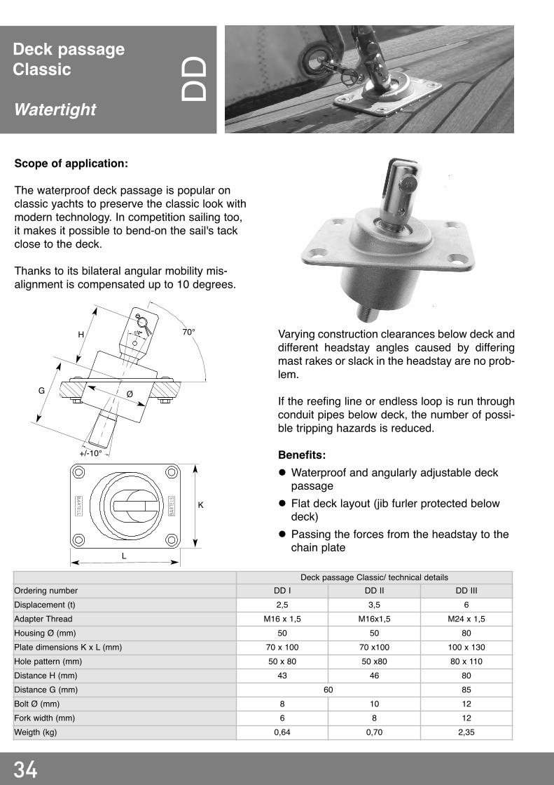
Deck passageClassic
Watertight DD
Deck passage Classic/ technical detailsOrdering number DD I DD II DD IIIDisplacement (t) 2,5 3,5 6Adapter Thread M16 x 1,5 M16x1,5 M24 x 1,5Housing Ø (mm) 50 50 80Plate dimensions K x L (mm) 70 x 100 70 x100 100 x 130Hole pattern (mm) 50 x 80 50 x80 80 x 110Distance H (mm) 43 46 80Distance G (mm) 60 85Bolt Ø (mm) 8 10 12Fork width (mm) 6 8 12Weigth (kg) 0,64 0,70 2,35
Scope of application:
The waterproof deck passage is popular onclassic yachts to preserve the classic look withmodern technology. In competition sailing too,it makes it possible to bend-on the sail's tackclose to the deck.
Thanks to its bilateral angular mobility mis-alignment is compensated up to 10 degrees.
Varying construction clearances below deck anddifferent headstay angles caused by differingmast rakes or slack in the headstay are no prob-lem.
If the reefing line or endless loop is run throughconduit pipes below deck, the number of possi-ble tripping hazards is reduced.
Benefits:l Waterproof and angularly adjustable deck
passagel Flat deck layout (jib furler protected below
deck)l Passing the forces from the headstay to the
chain plate
K
Ø
H
L
70°
+/-10°
G

35
Thread connectorfor below deck installationof F and FEGA
Thus a rigid extension can be installed betweenthe chain plate and the jib furler. The thread con-nector has two opposite threaded holes for a setscrew.Above about a 120 mm distance between furlerand chain plate, a security turnbuckle with alarger adjustment range can also be used.(Further details of the security turnbuckle onrequest).
Jib furler classic with thread connector/ technical details
Ordering number F I-2 F II-2 F III-2 F IV -2 F V-2
Suitbale deck passage DD DD I DD II DD III
Smallest legth (mm) - O 143 163 188 220 295
Length jib furler with thread connector (mm) - M 100 120 145 158 233
Bolt Ø (mm) 8 10 12
Jib furler endless with thread connector/ technical details
Ordering number FE I-2 FE II-2 FE III-2 FE IV -2
Suitbale deck passage DD DD I DD II DD III
Smallest legth (mm) - O 143 164 188 223
Length jib furler with thread connector (mm) - M 100 120 145 158
Bolt Ø (mm) 8 10 12
Scope of application:
The thread connector makes the connection ofthe jib furler with the deck passage. In order toachieve a shorter overall length it is an integralcomponent of the item "jib furler with thread con-nector". Example: FIII-2 (extension -2). The thread connector can also be retrofittedrespectively to existing Bartels furlers. Thethread connector provides another 10-15 mm oftensioning way beyond its minimum screw-indepth, depending on the size.
OM
O
M

36
Deck passageS-Series(non rotating headstay)
Watertight
D-S
Scope of application:
The deck passage D-S is used on boats ofapproximately 40-60 feet. In combination withcorresponding furlers below deck, systems arecreated which preserve the appearance of clas-sic yachts and also to allow a low attachmentpoint for the sail tack in modern yachts.
Since with the same boat length the total weightand the dimensions of the forestay can varywidely depending on the boat design, Bartelsoffers this deck passage for pin systems of 16mm or 19 mm, corresponding to headstay sizesof 7 - 12mm with 1x19 wire rope, rod or dyformof 7 - 10 mm (thread UNF 5/8 or UNF 3/4).
On the deck passage D-S, the headstay doesnot turn. The bearings of the jib furler are notloaded by the tensile forces of the headstay.Therefore, the highest loads will be easilyendured and the tensile forces transmitted to thethe chain plate. The entire unit headstay staysvertically movable inside the deck housing.Therefore a load bearing bolt can be alsoinstalled instead of the lower bolt.
Foto
: Spir
it Yac
hts,
Spirit
76
Benefits:l Lowest possible bending-on point for the tackl The appearance of classic yachts is largely
preservedl Through-deck fixture with ball joint compen-
sates for minor misalignment during installa-tion
l Headstay connector allows angular move-ment by ball terminal.
l Tensile forces of the forestay do not affect hebearings
l Integrated tack swivel
370
mm +
/- 30
mm(F
or e
lectric
driv
e wi
th 70
0W =
370
+ 30
mm)
Drive
opti
ons:
manu
ell, e
lectric
(see
also
page
37)

37
Foto
: Spir
it Yac
hts,
Spirit
52
Decks passage S-Series/ technical detailsOrdering number D-S (on request)Drive Manual ElectricSuitable Furler FIV-SL FV-SL FE V-SL 500W (12/ 24V) 700W (12/24V) 1200W (12/24V)Weight of D-S with Furler (kg) 8,0 9,4 8,2 16,0 23,0 23,0Headstay Ø (mm) up to 7 7-12 < 18Yacht size (ft) 38-40 40-60 60-100
Min. installation space belowdeck (mm)
340Note: Consider deck thickness and distance to inner hull wall
according to jib furler typ
370Note: Consider deck thickness and dis-tance to inner hull wall according to jib
furler typFoil BA II R20 R20/ R30 R40/ R50
D2-213-xD2-211-x D2-212-x(System overview on page 20-21) (System overview on page 22-23)

38
Telescope coupling RKScope of application:
The telescopic coupling set transfers the torquefrom the jib furler onto the foil without the possi-bility of unscrewing itself like a turnbuckle.Additionally it makes possible to adjust thelength of the entire forestay to compensate formeasurement tolerances and to adjust the mastrake.
Telescope coupling/ technical detailsOrdering number RKS I RKS II RKS IIIFoil BA I BA II (others on request) R20 (others on request)Connection Eye terminal with ring Special terminalHeadstay Ø (mm) ≤ 5 ≤ 7 ≤ 8Bolt Ø (mm) 8 12Fork width (mm) - B 6 10 12Distance (mm) - T 150 200Legth adjustable (mm) - L 410 - 530 480 - 660Adjust increment (mm) 10 15 15
Suitable foil shoe RKS I – BA I RKS II – BA IRKS II – BA II
Upon request also for third-party foils
Special Terminal:The special terminal allows the mounting andpossibly later exchange of the foils with tubularcross-section.
By different spacing of holes drilled into theinner and outer parts and switching the bolt fromPos. A to B, small step distances can beachieved. The final forestay tension is appliedby the backstay or running backstays.
Special terminal/ technical detailsOrdering number 39-M10 39-M12 39-M14 39-M16Suitable for headstay Ø (mm) 5 6 7 8
B
T
L
Pos. APos. B

39
Three hole plateswith/ without snap shaklewith/ without ringFour hole plates
Three-hole plate:
In jib furler systems with halyard swivel for cableheadstays three hole plates connect jib furler ordeck passage with the headstay. In systemswith foil the three hole plates connect the jibfurler or the deck passage with the telescopiccoupling set.
Four-hole plate:Four-hole plates are used in jib furling systemswith tackle to attach the headstay, the tack andthe halyard running along the headstay to thetackle above the jib furling system.
18/6
Three hole plates/ technical detailsOrdering number (Three hole plates single) 18-6 18-9 18/10-II 18/10-III 18/10-IVOrdering number (Three hole plates with snap shakle) 18/6-S 18/9-S 18/10-II-S 18/10-III-S 18/10-IV-SOrdering number (Three hole plate with ring) -- 18/9-R 18/10-II-R 18/10-III-R --Hole Ø (mm) 8/8/12 8/8/08 12/12/12 12/12/12 12/12/12Thickness (mm) 5 5 8 (2x4) 10 (2x5) 12 (3x4)Suitable for use with classic jib furler F I F II F III F IV F VSuitable for use with endless jib furler -- FE I, FE II FE III FE IV --
Suitable for classic decks passage -- DD I DD II DD III DD III (Stag Ø8mm)
Four hole plates/ technical detailsOrdering number (Four hole plate) 17/2 17/4 17/5 17/6Hole Ø (mm) 8 - 8 8 - 10 12 - 12 12 - 12Thickness (mm) 4 5 8 (2x4) 10 (2x5)Suitable for use with classic jib furler F I F II F III F IVSuitable for use with endless jib furler FE I FE II FE III FE IV
17/6
18/6-S
The bending of the sail tack is especially simpleand safe to a three-hole plate with a welded-onsnap shackle. Sails with sewn-on snap shacklesare attached to three-hole plates with rings.

40
Halyard swivelfor foil FSScope of application:
Sliding halyard swivels for foils allow the use ofthe jib halyard on the mast by letting the innerpart rotate with the foil and the outer part toremain stationary.
In all systems with sliding halyard swivel thestrained halyard should run at an angle of 5 to10 degrees to the forestay and the distancebetween the sliding halyard swivel and the mastsheave should be as short as possible. Here,the stretching of the luff has to be observed sothat the halyard swivel does not push up the endcap in the set condition.
FS II R20-1
Halyard swivel for foil/ technical detailsOrdering number FS II FS III R20-1Max. foil Ø (mm) 24 32 35Legth A‘ (mm) 115 150 --Length A (mm) -- -- 95Gliding insert BARTELS I BARTELS II R20-1Weigth (kg) 0,35 0,62 1,13
Jibs with a short luff have to be extended with awire pennant so the halyard swivel always is atthe top. With a halyard running parallel to theforestay there is always a risk that it wraps itselfaround the foil and the further furling is blocked.
A‘
A

41
FoilBAx
Rxx
Scope of application:
Foils accept sails with luff tape in a groove. Thepiping of the luff tape should slide easily into thegroove, but must not be jammed into the slotunder load when sailing. For the three foil illus-trated here, the nominal thickness of the pipingis 5 mm.
With closed tubular foils, the headstay connec-tion should be constructed in such a way thatthe foil can be installed and disassembled overit, at least at the bottom.
Foil/ technical detailsOrdering number BA I BA II R20 > R20 on requestMaterial Alu Alu AluColor Silver anodised Black anodised (silver on request)Legth/ element (m) 2 2 3Weigth/ element (kg) 0,4 0,47 0,82Headstay Ø (mm) ≤ 6 ≤ 7 ≤ 10Working legth (m) ≤ 9 ≤ 13 ≤ 18
BA I BA II R20
Luff tape Ø 5mm
For details or names of the individual parts seethe installation instructions for the correspon-ding foils. This is under www. bartels.eu avail-able in the download area or mailed uponrequest.
The pre-feeder makes a second crew person onthe the forepeak unnecessary.
Note: The feeding slot for sails into the foil-should be about 0,5 - 0,8 m above the deck foroptimal operation of the sail pre-feeder. The pre-feeder is installed about 0,2 - 0,3 m below thebottom end of the sail groove to the telescopiccoupling with a bridle.
Sail pre-feederThe Sail pre-feeder makes inserting the jib intothe foil easy. (Article number: S)

42
Halyard swivel for wire headstay FSScope of application:
Halyard swivels for wire headstays make the uti-lization of the existing jib halyard on the mastpossible because the inner part rotates with theforestay and the outer part remains stationary.The halyard swivel must be pushed onto thecable in the proper position before the halyardterminal is swaged.
In all systems with sliding halyard swivel thestrained halyard should run at an angle of 5 to10 degrees to the headstay and the distancebetween the sliding halyard swivel an the mastsheave should be as short as possible.
Halyard swivel for wire headstay/ technicaldetails
Halyard swivel for wire headstay with coupling terminal/technical details
Ordering number FS I FS II–D-6 FS II-D-7 FS II-D-8 FS II–DK-5 FS II–DK-6 FS III-DK-7 FS III-DK-8Wire Length (m) < 10 > 10Headstay Ø (mm) 4 - 5 6 7 8 5 6 7 8Gliding insert Ø (mm) 5,5 6,5 8 9 13,5 13,5 16,5 16,5Weigth (kg) 0,18 0,46 0,60Length A (mm) 63 140 150Material gliding insert Bronze (corosion resistant)Cage Ø (mm) 25 35 35 35 42 42 50 50
FS II-D FS II-DK (For coupling terminal)
Here, the stretching of the luff has to beobserved so that the halyard swivel does not hitthe upper terminal in the set condition.
By installing a halyard lead eye, the angle canbe maintained. Jibs with a short luff have to beextended with a wire pennant so the halyardswivel always is at the top. With a halyard run-ning parallel to the forestay there always is a riskthat it wraps itself around the forestay and fur-ther furling is blocked.
A

43
Coupling terminalMT
Scope of application:
Beyond forestay lengths of 8 to 9 meters werecommend using a halyard swivel with couplingand a coupling terminal. In the top position, thehalyard swivel engages into the longitudinalgroove of the coupling terminal. Thus the sailhead is rotated and flogging of the rolled up sailin the head area is prevented during strongerwind gusts.
The rolling-up direction must always be proper-ly selected so that the forestay cable in not twist-ed in the unraveling direction but rather is turnedtight. In most halyards, cable of the style 1x19 isused (z-turned). This means a winding up inclockwise direction as viewed from above. Aspecial size for rod -17 (Ø 8,4mm) is availableon request.
The length of the luff must be adjusted so thatthe sliding halyard swivel sits at about the mid-dle of the of the coupling terminal when the hal-yard is extended with a wire pennant.
Benefits:l Safe catching of the sail head during furling l Unwrapping of the furled sail in the sail head
area is prevented during strong winds l The appearance of classic yachts is main
tained by continued use of hank-on sails
Halyard swivel with cou-pling insert (page 42)
Wire/ Rod rolled-inRod from 7mm with swage head
Headstay: Wire or Rod
Lappet/ Fork/ T-Toggle (page 46)
Headstay swivel (page 44)
Coupling terminal/ technical detailsOrdering number 37/39-5 VST 37/39-6 VST 37743-7 VST 37/43-8 VSTWire Ø (mm) 5 6 7 8Length - L (mm) 395 395 430 430Schaft Ø - D (mm) 13 13 16 16Weigth (kg) 0,37 0,37 0,6 0,64
L
Ø D

44
HeadstaySwivel ST
WScope of application:
The headstay swivel is used in systems in whichthe forestay turns. Available in the version hal-yard swivel (with a chain link for larger halyardshackles) as swivel on a spinnaker halyard orflying systems.
The swivel must be free to move in the pullingdirection of the forestay without touching themast or jamming the halyard in the halyard exitsheave. Other existing halyards must not caughtby rotating parts and must be kept free runningby lead eyes and spinnaker suspension jigs(see page 47)
Headstay swivel/ technical detailsOrdering number STW I STW II-5 STW II-6 STW III STW IVDisplacement (t) 1,5 2,5 3,5 6Headstay Ø (mm) 4 5 - 6 6 7 - 8Breaking load (kN) 20 32 40 60Working loadl (kN) 10 16 20 30Length A (mm) 63 81 80 97 103Bolt Ø (mm) 7 8 10 12Body Ø (mm) - F 30 35 42 50Fork width (mm) - E1 6 - 6 6 - 6 6 - 9 8 - 8 10 -10Weigth (kg) 0,20 0,30 0,30 0,60 0,90
For connecting the forestay swivel to the mast,straps, brackets, forks and T-toggles are avail-able (see page 46). In special halyards (CFRPmasts, carbon fiber mast nose, double -forestays, etc.) please consult us with detailedsketch and picture.
Ø F
E1
A

Other existing halyards must not caught byrotating parts and must be kept free by leadeyes and spinnaker suspension jigs (see page47).
For connecting the forestay swivel to the mast,straps, brackets, forks and T-toggles are avail-able (see page 46). In special cases (CFRPmasts, carbon fiber mast nose, double -forestays, etc.) please consult us with detailedsketch and picture.
45
Swivelwith cable sheaveW
SScope of application:
The swivel with cable sheave is used in a furlingsystem with tackle, where the separate halyardis returned parallel to the forestay to the furler.The swivel must be able to move freely free inthe pulling direction of the forestay withouttouching the mast or jamming the halyard in thehalyard exit sheave.
Swivel with sheave/ technical detailsOrdering number WS 0 A WS 0 B WS I WS II WS III WS IVDisplacement (t) 0,5 1,5 2,5 3,5 6Headstay Ø (mm) 3 4 5-6 6 7 - 8Breaking load (kN) 6 20 32 40 60Working load (kN) 3 10 16 20 30Length (mm) - A 85 87 109 136 143Bolt Ø (mm) 6 7 8 10 12Body Ø (mm) - F 22 30 35 42 50Fork width (mm) - E1/E2 6 6 - 7 6-9 8 - 9 10 - 11Weight (kg) 0,10 0,11 0,24 0,38 0,75 1,25
Ø F
E2
A
E1

46
Connectionsbetween top swiveland mast
Lappet L (mm) B (mm) Ø D1(mm) Ø D2 (mm) W (mm) S (mm) Bruchlast (kN)L34-20-6 34 20 8 8
--
630
L48-20-6 48 20 8 8 6L50-25-6 50 25 8 10 6 40L50-25-8 50 25 10 10 8 50L75-30-10 75 30 12 12 (16) 10 60Fork L (mm) B (mm) Ø D1(mm) Ø D2 (mm) W (mm) S (mm) Bruchlast (kN)G34-20-3 34 20 8 8 6 6
30G48-20-3 48 20 8 8 6 6G75-25-3 75 25 10 10 15 6 40G65-25-4 65 25 10 10 10 8 50G75-30-5 75 30 12 12 10 10 60T-Toggle L (mm) B (mm) Ø D1(mm) Ø D2 (mm) W (mm) S (mm) Bruchlast (kN)T4-70 70
--
8
-- --
7.530T4-115 115 8 7.5
T5-90 90 8 9T6-90 90 10 12.5 40T7-90 90 12 14
60T8-90 90 12,5 16
Lappet Fork T-Toggle
mast or jamming the halyard in the halyard exitsheave (see picture on the right, for a barelypermissable situation).Other existing halyards must not caught byrotating parts and must be kept free running bylead eyes and spinnaker jigs.
Ø D1
SB
L
W
1/2*S
L
LS
Ø D1 Ø D1
Ø D2Ø D2
B
S
Scope of application:
For the attachment of top swivel to mast, lap-pets, forks and T-toggles are available to choosefrom. In special (CFRP masts, carbon fiber mastnose, twin forestays, etc.) please consult us withdetailed sketch and picture.The swivel must be free to move in the pullingdirection of the forestay without touching the

47
In all systems with sliding halyard swivel, thehalyard should run at an angle of 5 to 10degrees to the forestay and the distancebetween the sliding halyard swivel an the mastsheave should be as short as possible. Here,the stretching of the luff has to be observed sothat the halyard swivel for cable does not hit theupper terminal, or the halyard swivel for extru-sion forestays not the end cap.
By screwing on a halyard lead eye the anglecan be maintained. Jibs with shorter luffs mustbe extended by one permanently attachedcable pennant so that the halyard swivel isalways at the top. With a halyard running paral-lel to the forestay, there is always a risk that itwraps itself around the cable or extrusion head-stay and further furling is blocked. (See alsopage 52)
Halyard guiding

48
Accesoiresfor flying sail furlingsystems
Triangular plate
On flying headsails (Code 0) the luff must bereinforced. One possibility is the use of twocables with a webbing in between to keep thedistance.Triangular plates installed in pairs with a brack-et accept the cables and the webbing and trans-mit the forces onto jib furler and swivel.
Snap shackle with lashing (below)
Snap shackles with lashings are used for quickbending on and off of the jib furler of furling sys-tems run in a flying state (if the furler is sup-posed to remain on the sail). The lashing pre-vents tipping of the snap shackle when openingand closing.
Shnap shackle with lappet / technical details
Ordering number 5879-1 5879-2 5898-3 5899-4
Size I II III IV
Suitable for jib furler FE I FE II FE III FE IV
Triangular plate/ technical details
Ordering number 18/12 18/13 18/14-6 18/14-8
Size I II III IV
Headsail area Top-Genua (m2) < 30 < 50 < 70 < 100
Webbing width (mm) 16 20 30
Long hole (mm) 8 x 12 12 x 16 12 x 16
Hole Ø (mm) 6 8 10
Thickness (mm) 4 6 8

49
Aluminum thimbles
Aluminum thimbles are matched to theCompetition Series. The elongated hole is pro-vided for attachment of the head of a gennakersail with a multiply looped thin high-strengthline. With the sufficient length of 0,15 - 0,20 mof the start of the winding process from above isfacilitated.
Accesoiresfor flying sail furlingsystems
Snap shackle with fork
Snap shackles with forks are used for quickbending and unbending of the jib furlers fromthe Competition Series. Here, we use high-ten-sile forged shackles. Please observe: If the end-less loop is to be unbent together with the jibfurler, the line guidance must be removable too(stanchion blocks with snap shackles, page 56).
Snap shakle with fork/ technical detailsOrdering number 5979-6 5998-6 5999-6Distance jib furler bolt to chain plate bolt (mm) - L 39 54 65Bow eye Ø (mm) - T 12 15 20Weigth (kg) 0,05 0,12 0,25
B
W
D
Aluminium thimble/ technical details
Ordering number 42/111 42/114 42/116
Width (mm) - B 20 28 28
Bolt Ø - D (mm) 10 12 14Thickness (mm) - W 15 15 15
T
W
L L
T

50
Scope of application:
Halyard swivels are used in jib furling systemsfor flying sails (Code 0 or Gennex). The swivel isalso often used on spinnakers to enable unfurl-ing of the head even under high loads.
Halyard swivel/ technical detailsClassic Competition
Ordering number FAW 0 FAW I FAW II FAW III FAW IV FAW II-L FAW III-L FAW IV-LGennaker (m2) < 30 < 50 < 70 < 150 < 200 < 70 < 150 < 200Top genua (m2) 10 - 20 20 - 30 30 - 50 50 - 70 70 - 100 30 - 50 50 - 70 70 - 100Breaking load (kN) 6 20 32 40 60 32 40 60Working load (kN) 3 10 16 20 30 16 20 30Length A (mm) 59 63 81 97 103 84 99 114Length A‘ (mm) 82 91 120 145 160 108 132 154Body Ø (mm) - F 22 30 35 42 50 35 42 50Bolt Ø (mm) 6 7 8 10 12 10 12 14Fork width (mm) - B 6 6 6 8 10 17 20 20Weigth (kg) 0,09 0,20 0,35 0,65 0,95 0,30 0,57 0,80
The square meter specifications serve as guide-line values. Please indicate boat type, boatweight and specify the wind velocity up to whichthe sail is to be used. The swivels for spinnakerscan be chosen in smaller sizes. For catamaransand top genoas made of heavier cloth, we rec-ommend a larger halyard swivel if in doubt.
Ø F
B
A
Ø F A‘
B
A
A‘
Halyard swivel
Code 0GennexSpinnaker halyard FA
WFA
W L

51
Jib furler endless competition series for GENNEX with anti-torsion rope and thimble (page 33)
52
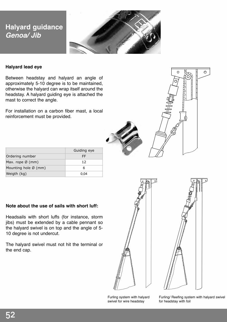
Halyard guidanceGenoa/ Jib
Halyard lead eye
Between headstay and halyard an angle ofapproximately 5-10 degree is to be maintained,otherwise the halyard can wrap itself around theheadstay. A halyard guiding eye is attached themast to correct the angle.
For installation on a carbon fiber mast, a localreinforcement must be provided.
Guiding eye
Ordering number FF
Max. rope Ø (mm) 12
Mounting hole Ø (mm) 6Weigth (kg) 0,04
Note about the use of sails with short luff:
Headsails with short luffs (for instance, stormjibs) must be extended by a cable pennant sothe halyard swivel is on top and the angle of 5-10 degree is not undercut.
The halyard swivel must not hit the terminal orthe end cap.
Furling system with halyardswivel for wire headstay
Furling/ Reefing system with halyard swivelfor headstay with foil

53
Spinnaker HalyardGuidance
Scope of application:
The spinnaker suspension jig keeps the spin-naker halyard free of the top swivel, the halyardswivel and sail head.
Depending on the kind of rigging and the exit ofthe spinnaker halyard from the mast, the hal-yard can be led directly through the suspensionjig or through an additional block (see alongsidegraphic). Two sturdy stainless steel sizes areavailable.
Note about adjustments to diverse mastgeometries:
The spinnaker suspension jig is fastened to analuminum mast with rivets, and with screws to awooden mast. By bending the width of the sus-pension jig can be adjusted to the diameter ofthe mast at hand.
Installation on carbon fiber masts only with suit-able local reinforcements.
Spinnaker suspension
Ordering number SP I SP II
Height H (mm) 140 190
Length L (mm) 200 250
Width flexibel (mm) 60 - 100 100 - 150
Wire Ø (mm) 6 8
Weigth (kg) 0,23 0,41
H
L
54
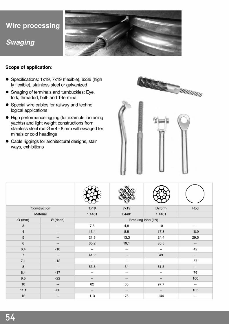
Wire processing
Swaging
Scope of application:
l Specifications: 1x19, 7x19 (flexible), 6x36 (highly flexible), stainless steel or galvanized
l Swaging of terminals and turnbuckles: Eye, fork, threaded, ball- and T-terminal
l Special wire cables for railway and technological applications
l High performance rigging (for example for racingyachts) and light weight constructions from stainless steel rod Ø = 4 - 8 mm with swaged terminals or cold headings
l Cable riggings for architectural designs, stairways, exhibitions
Construction 1x19 7x19 Dyform RodMaterial 1.4401 1.4401 1.4401
Ø (mm) Ø (dash) Breaking load (kN)3 -- 7,5 4,8 10 --4 -- 13,4 8,5 17,8 18,95 -- 21,8 13,3 24,4 29,56 -- 30,2 19,1 35,5 --6,4 -10 -- -- -- 427 -- 41,2 -- 49 --7,1 -12 -- -- -- 578 -- 53,8 34 61,5 --8,4 -17 -- -- -- 769,5 -22 -- -- -- 10010 -- 82 53 97,7 --11,1 -30 -- -- -- 13512 -- 113 76 144 --

55
Scope of application:
In racing yachts, rod is increasingly used forstays and shrouds. The rod used is a highstrength, stainless spring steel. Due to the high-er strength as compared to conventional wirerope 1x19, the rod diameter can be chosensmaller and lighter. Another advantage is the higher rigidity. Rodstretches less than wire rope 1x19 and exhibitsless permanent stretching under loads suitablefor the diameter. Wire rope 1x19 grows longerand longer in the first few years, depending onthe load.
Rigid rod must not be kinked or injured in someother way at sharp angles, otherwise sooner orlater breakage will occur. Bending stresses orbuckling risks can be avoided by articulatedconnections.
Up to about 6 - 7 mm, rod may be rolled into ter-minal shanks. But the full pull-out force up todestruction of the rod can only be achieved bylow-notch profiling of the rods before the rolling.We strictly discourage from improper filing, tap-ping or hammering.
From 7 mm up, we recommend terminals withcold heading. A matching threaded socket is tobe pushed on the rod. This connection is partic-ularly safe because the cold heading may bestressed up to the maximum breaking strengthof the rod.
Rod processing
Cold heading
56
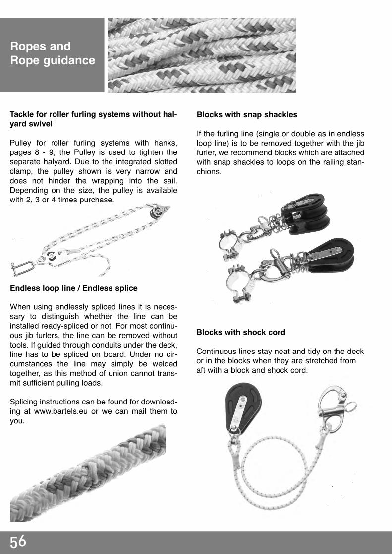
Ropes andRope guidance
Tackle for roller furling systems without hal-yard swivel
Pulley for roller furling systems with hanks,pages 8 - 9, the Pulley is used to tighten theseparate halyard. Due to the integrated slottedclamp, the pulley shown is very narrow anddoes not hinder the wrapping into the sail.Depending on the size, the pulley is availablewith 2, 3 or 4 times purchase.
Endless loop line / Endless splice
When using endlessly spliced lines it is neces-sary to distinguish whether the line can beinstalled ready-spliced or not. For most continu-ous jib furlers, the line can be removed withouttools. If guided through conduits under the deck,line has to be spliced on board. Under no cir-cumstances the line may simply be weldedtogether, as this method of union cannot trans-mit sufficient pulling loads.
Splicing instructions can be found for download-ing at www.bartels.eu or we can mail them toyou.
Blocks with snap shackles
If the furling line (single or double as in endlessloop line) is to be removed together with the jibfurler, we recommend blocks which are attachedwith snap shackles to loops on the railing stan-chions.
Blocks with shock cord
Continuous lines stay neat and tidy on the deckor in the blocks when they are stretched fromaft with a block and shock cord.
57
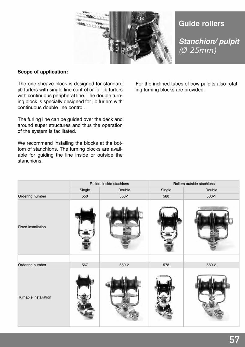
Guide rollers
Stanchion/ pulpit(Ø 25mm)
Rollers inside stachions Rollers outside stachionsSingle Double Single Double
Ordering number 550 550-1 580 580-1
Fixed installation
Ordering number 567 550-2 578 580-2
Turnable installation
Scope of application:
The one-sheave block is designed for standardjib furlers with single line control or for jib furlerswith continuous peripheral line. The double turn-ing block is specially designed for jib furlers withcontinuous double line control.
The furling line can be guided over the deck andaround super structures and thus the operationof the system is facilitated.
We recommend installing the blocks at the bot-tom of stanchions. The turning blocks are avail-able for guiding the line inside or outside thestanchions.
For the inclined tubes of bow pulpits also rotat-ing turning blocks are provided.

58
Installation hints for therope guidance on and below deck
For drum furlers applies: The line should bebraided and as hard as possible. If this is not ful-filled the line can jam itself (the outer layers onthe drum can cut into the inner layers). Thediameter and length has to be adjusted to thefurler and the length of the sail's luff. With end-less furlers applies: braided line should be usedand the line diameter should match the furler. The line must run freely from the cutout (notpulling over the edge)
With drum furlers, the rope should run out asvertically to the turning axis of the furler as pos-sible. This can be adjusted with turning blocks.The axis of rotation of the jib furler must adjustitself freely in the direction of pull, therefore suf-ficient clearance at the chain plate is to beensured. The furler must not jam in the slot onthe chain plate. If necessary, a forked togglemust be installed. The housing may not touchthe bow pulpit or other components (anchorroller or rocker) since the forestay moves aboutunder sail.
With endless furlers applies: The rope outletmay vary up to 15 degree from the jib furler'saxis of rotation due to the integrated guidingsheaves. Generally the rope run out is parallel tothe deck. The rope can be led over port or star-board or peripherally.
An UV-protection sewed on the leech has to beput on the port side when furling clockwise. Fornormal jib furlers with endless rope the sense ofrotation will be always clockwise. In case of anexisting sail with UV protection on starboardplease indicate when ordering a jib furler end-less for changing the sense of rotation!The rope outlet of all jib furlers, if drum or end-less type, can be adjusted in 12 positions. Thusall jib furlers can be mounted on a chaine platetransverse too, and the rope outlet can beturned in correct position.
winding direction: right hand
UV-protectionBackbord outside

59
If the furler is mounted below deck, the rope canalso be elegantly hidden below deck. For instal-lation below deck, plastic electric conduit tubinghas proven itself well. The pipes offer low frictionand prevent tangling of the furling line. Thepipes have to be secured against shifting length-wise.
In narrow bows, the conduit pipe may be leftunfastened in the direction of the jib furler for thelast 0,5 to 0,8 m. In wide bows, the furling lineshould be led parallel into the conduit pipe byadditional blocks near the hull.
The figure shows a complete line layout to star-board. The line can also be led to port or periph-erally.
In the area of the cockpit, the furling line mustbe secured against accidental unfurling of thesail by a cam cleat (or others).
With dual lines (when using endless furlers)both lines must be always secured. The fasten-ing options are numerous - please contact usfor an individual consultation.
Installation hints for therope guidance on andbelow deck
!
!
!

60
1 General provisions1. The supplier’s business terms apply exclusi-vely; the supplier shall not recognise conflic-ting conditions of the purchaser or those thatdiffer from the supplier’s terms, unless thesupplier has expressly approved their validityin writing. The supplier’s business terms shallalso apply to future business with the purcha-ser.
2. The supplier shall unreservedly retain itsexploitation right pertaining to property andcopyright law for drawings and blueprints. Thedocuments may only be made accessible tothird parties after prior approval from the sup-plier and must be returned to the latter ondemand, if the contract is not awarded to thesupplier.
2 Prices and terms of payment1. Prices are ex works excluding packaging,plus effective VAT and other costs (e.g. customsduty, insurance premiums).
2. If the supplier has taken on installation orassembly, and nothing else has been agreed,the purchaser shall bear all necessary additio-nal costs, in addition to the agreed remunera-tion (e.g. travel expenses, transportation oftools).
3. Unless stated otherwise, the net remunerati-on (without discount) is due for payment wit-hin 30 days from the invoice date. Should thepurchaser default, the supplier is entitled todemand interest on arrears of 5% p.a. abovethe respective base lending rate according to§247 German Civil Code (BGB). In the eventthat the supplier is able to prove higher dama-ge caused by default, the supplier is entitled toclaim this.
4. The purchaser is only entitled to offset rightsif his counterclaims are established as beinglegally valid, undisputed, or recognised by thesupplier
3 Extended reservation of title1. The product shall remain the supplier’sunrestricted property until all claims from thetotal business association have been settled infull. Should the supplier take back the deliveryitem in exercising his reservation of title rights,this shall only constitute withdrawal from thecontract if the supplier expressly declares this.Pledging or the collateral assignment of thereserved product or the transferred claims isnot allowed. The supplier must be informedimmediately about seizures, confiscations, ofother disposal or interventions by third par-ties, giving exact details of the distrainer orthird party. The supplier is entitled to demandcompensation from the purchaser for the costsincurred.
2. The purchaser is entitled to resell or repro-cess the object taking into account the follo-wing conditions: the purchaser shall herewithtransfer his claims, with all subsidiary rightsfrom the resale of the reserved product to thesupplier. The purchaser is authorised to collectthe transferred claims, as long as it meets hispayment obligations. The collection authorisa-
tion becomes invalid if the purchaser defaultson payment. In this case the supplier is autho-rised by the purchaser to inform the purcha-ser's clients about the transfer and to collectthe claims himself. The purchaser must provi-de the necessary information to assert thetransferred claims and must consent to anexamination of this information. It must espe-cially be submitted to the supplier, on demand,an exact list of the claims due (with name andaddress of the clients, size of the claim, invoicedate).
3. Should the reserved product be connected,mixed or processed by the purchaser to produ-ce a new movable object, this shall take placefor the supplier without the latter being placedunder any obligation as a result of this. Thepurchaser shall not acquire ownership of thenew object as a result of it being connected,mixed or processed according to §947 ff.German Civil Code (BGB). In the event thatobjects that do not belong to the supplier areconnected, mixed or processed, the suppliershall acquire part ownership of the new objectaccording to the ratio of the invoiced value ofits reserved product to the total value. Thepurchaser shall keep the reserved product safefor the supplier free of charge. He shall insureit against standard risks (e.g. fire, theft, water)on the normal scale at its own expense.
4. Should the value of the existing collateral forthe supplier exceed the latter's total claims bymore than 20%, the supplier is obliged torelease collateral of his choice to this extent atthe supplier’s request.
4 Delivery1. Compliance with agreed time limits for deli-veries assumes the punctual receipt of alldocuments to be delivered by the purchaser,necessary licences and clearances, especiallyof plans, and compliance with the agreedterms of payment and other obligations by thepurchaser. Should these obligations not be meton time, the time limits shall be extended to anappropriate extent; this does not apply if thesupplier is responsible for the delay.
2. Delivery dates are only considered fixeddates upon the supplier's written approval.
3. Part deliveries shall be accepted by thepurchaser.
4. Deliveries shall be accepted by the purcha-ser, even if the goods have negligible defects.
5 Transfer of risk1. For customers the risk is transferred upondelivery or on default of acceptance; for regi-stered merchants – including the case of car-riage-paid delivery – as follows:a) in the case of deliveries without assembly,when they have been brought for forwardingor picked up. Deliveries may be insured by thesupplier against standard transport risks at therequest and expense of the purchaser,b) in the case of deliveries with assembly, onthe date of acceptance into the purchaser’sown company or, if agreed, after a faultlesstest-run.
2. If forwarding, delivery, the start, implemen-tation of assembly, acceptance into the purcha-ser’s own company or the test-run is delayedfor reasons which the purchaser is responsiblefor, or the purchaser defaults on acceptance forother reasons, the risk is transferred to thepurchaser.
6 Assembly1. The purchaser takes on the following at ownexpense and provide on time:a) the necessary commodities and materials,such as scaffolding, lifting gear and other devi-ces, fuels and lubricants,b) energy and water at the place of use,including connections, heating and lighting,c) protective clothing and equipment neces-sary due to the special circumstances at theassembly site.d) authorized personnel for the operation ofthird party on-site installations.
2. Before the commencement of assembly, thenecessary provision of materials and objectsfor starting work must be located at the instal-lation or assembly site and all preliminarywork prior to commencing assembly must beso well advanced that installation or assemblycan be started as agreed and implementedwithout any interruptions. Delivery roads andthe assembly site must be cleared.
3. Should installation, assembly or start-up bedelayed for reasons beyond the supplier’s con-trol, the purchaser must to a reasonable extentbear the costs for waiting time and also fornecessary additional travel carried out by thesupplier or the assembly staff.
4. Should the supplier request acceptance ofthe delivery after completion, the purchasershall carry this out within two weeks. Shouldthis not take place, the acceptance shall beconsidered completed. The acceptance shallalso be considered completed if the deliveryhas been used (after completion of an agreedtest phase, if applicable).
7 Warranty1. All parts or services that show a fault withinthe statutory limitation period must either berepaired, redelivered or refurnished by thesupplier, depending on which option he choo-ses, if the cause already existed at the timewhen the risk was transferred.
2. Claims for faults shall become statute-bar-red, if the purchaser is a registered merchant,in twelve months from the due date of the faultclaim, at the longest, however, in 24 monthsfrom delivery of the item, for consumers in 24months, if not agreed expressly upon a longerwarranty period. This time limit also applies toindirect damage due to defects, if no claims intort have been asserted.3. The purchaser must notify faults to the sup-plier immediately in writing.
4. If defects are notified, payments by thepurchaser may be withheld on a scale that isreasonably proportionate to the faults thathave occurred. The purchaser may only with-
hold payments if a notice of defect is assertedand there is no doubt that it is justified. If thenotice of defect is wrong, the supplier is entit-led to demand compensation from the purcha-ser for the costs it has incurred.
5. Initially the supplier must always be allowedthe opportunity to meet its obligations after-wards within a reasonable limited period.
6. The purchaser may only withdraw from thecontract or reduce payment, if the supplierfails to meet his obligations at a later stage.
7. Claims made for defects shall not be recogni-sed if the quality of the product only variesnegligibly from the agreed quality, in the caseof natural wear and tear or if damage occursafter the risk has been transferred due toincorrect or negligent handling, excessivestrain, unsuitable operational equipment, oras a result of special external influences thathave not been allowed for in the contract. Ifimproper changes or repair work are carriedout by the purchaser or third parties, no claimsfor defects shall be accepted for these or theresulting consequences.
8. Claims made by the purchaser due to expen-ses that become necessary for the purposes ofrectifying faults, especially transport, travel,labour and material costs, are excluded, if theexpenses increase because the delivery itemhas been moved to a different location thanthe purchaser’s address or place of business.
9. Other claims by the purchaser against thesupplier and his vicarious agents due to a faultare excluded.
8 jurisdiction; applicable law1. The place of jurisdiction is Markdorf,Germany, in so far as the purchaser is a regi-stered merchant. The same place of jurisdic-tion applies if the purchaser has no generalplace of jurisdiction in Germany, moves hisplace of residence or normal abode out ofGermany after conclusion of the contract, orhis place of residence or normal abode is notknown on the date the suit is filed.
2. The substantive law of the Federal Republicof Germany shall exclusively prevail for alllegal relationships with the purchaser, withoutreferring them to another legal system. TheUnited Nations Accord of 04-11-1980 regardingsale of goods is not used.
9 Legal validityIf an individual provision becomes legallyineffective, it shall then be replaced by a legalprovision; the other sections of the contractshall remain in effect and binding for both par-ties.
CEO: Dipl.-Ing. Sven BartelsRegistration court AG Freiburg i. Br. HRB 581061USt–IdNr. DE811801546 (VAT Reg. No. / T.V.A)
Credit union (Volksbank) MarkdorfAccount 62338504 (IBAN: DE81690618000062338504)Bank code 69061800 (SWIFT/BIC: GENODE61UBE)
General business terms

BARTELS GmbHBergheimer Str. 2688677 MarkdorfGERMANY
Tel +49 (0)7544/95860–0Fax +49 (0)7544/95860–60Web http://www.bartels.euMail [email protected]
Contact
>> BARTELS.Made from stainless steel.
Made in Germany. <<
Foto: Spirit Yachts
BARTELS

BARTELS GmbHBergheimer Str. 2688677 MarkdorfGERMANY
Tel +49 (0)7544 95860–0Fax +49 (0)7544 95860–[email protected] www.bartels.eu
n Systems with Jib Furler Standard or Jib Furler Endless
n Systems On Deck or Below Deck
n Deck Passages Sealed and Angular Movable
n Furling Systems Flying for Headsails Without Hanks
n Furling Systems with Tackle for Headsails With Hanks
n Furling Systems with Halyard Swivel for Wire Forestay
n Reefing Systems with Foil
n Refitting of Own or Third-party Systems
© 2012 BARTELS GmbH. All rights reserved. Catalogue version: 10.2012.