
· Web viewFigure 16. Sequence diagram for LPU0731. ... Galois/Counter Mode ... Due to the fact...
117
Communication Standard Between AMI Application and Metering Infrastructure developed for ENERGA-Operator SA Version: 0.03 Date: 2011-07-31
-
Upload
nguyenthien -
Category
Documents
-
view
213 -
download
0
Transcript of · Web viewFigure 16. Sequence diagram for LPU0731. ... Galois/Counter Mode ... Due to the fact...

Communication Standard Between AMI Application and Metering Infrastructuredeveloped for ENERGA-Operator SA
Version: 0.03
Date: 2011-07-31
Contents1 Glossary of terms and acronyms......................................................................................................52 Introduction......................................................................................................................................83 Concept for the communication standard in DSO............................................................................9
3.1 Assumptions for the communication standard.........................................................................9
3.1.1 General assumptions.........................................................................................................93.1.2 Technical assumptions......................................................................................................9
3.2 Overall concept of the communication standard....................................................................10
3.2.1 Area of communication between SAK and concentrators..............................................113.2.2 Area of communication between concentrators and meters...........................................113.2.3 Area of communication between SAK and meters.........................................................123.2.4 Traffic prioritization.......................................................................................................133.2.5 Digital signatures............................................................................................................173.2.6 Concept of transport.......................................................................................................17
4 Meter Use Cases.............................................................................................................................20
4.1 Categories, Identifiers and Statuses of Meter Use Cases.......................................................204.2 List of Meter Use Cases..........................................................................................................214.3 Analysis of Meter Use Cases..................................................................................................21
4.3.1 Installation Category.......................................................................................................234.3.2 Configuration Category..................................................................................................304.3.3 Readouts Category..........................................................................................................344.3.4 Control Category............................................................................................................384.3.5 Reporting Category.........................................................................................................43
5 DCSML communication protocol..................................................................................................45
5.1 Description of Messages.........................................................................................................455.2 Protocol Grammar..................................................................................................................45
5.2.1 Basic definitions of SML data structures.......................................................................465.2.2 Basic structures of DCSML data....................................................................................535.2.3 DCSML Functions – associated with the operation of a concentrator...........................555.2.4 DCSML functions – associated with the operation of a meter.......................................57
6 Examples of queries and responses in DCSML (in APDU and source forms)..............................61
6.1 ASN.1 definition.....................................................................................................................616.2 Examples................................................................................................................................63
6.2.1 Example 1-1-1................................................................................................................636.2.2 Example 1-1-4................................................................................................................656.2.3 Example 1-5-1................................................................................................................676.2.4 Example 1-5-4................................................................................................................696.2.5 Example 5-1-1................................................................................................................716.2.6 Example 5-1-4................................................................................................................746.2.7 Example 5-5-1................................................................................................................796.2.8 Example 5-5-4................................................................................................................83
Document title: Communication Standard Between AMI Application and Metering Infrastructure 2 z 94
TablesTable 1. Glossary of terms and acronyms................................................................................................5Table 2. Categories of Meter Use Cases.................................................................................................20Table 3. Meter Use Cases with "A" status..............................................................................................21Table 4. DCSML Message List..............................................................................................................45Table 5. Significance of bits in the first byte of the TL-Field................................................................47Table 6. Significance of bits in subsequent bytes of the TL-Field.........................................................48
FiguresFigure 1. Areas of communication in the AMI system..........................................................................10Figure 2. Areas of communication in the AMI system – layers of the protocol....................................11Figure 3: Diagram of the sequence – single communication session PULL..........................................14Figure 4: Diagram of the sequence – two communication sessions PULL + PULL..............................14Figure 5: Diagram of the sequence – two communication sessions PULL + PUSH.............................15Figure 6: Diagram of the sequence – single communication session PUSH..........................................15Figure 7. LPU in Installation Category..................................................................................................23Figure 8. Sequence diagram for LPU01 – correct situation...................................................................24Figure 9. Sequence diagram for LPU02.................................................................................................25Figure 10. Sequence diagram for LPU03...............................................................................................25Figure 11. Sequence diagram for LPU04 – servicing mode...................................................................27Figure 12. Sequence diagram for LPU04 – without servicing mode.....................................................27Figure 13. Sequence diagram for LPU05...............................................................................................28Figure 14. Sequence diagram for LPU06...............................................................................................29Figure 15. LPU in Configuration Category............................................................................................30Figure 16. Sequence diagram for LPU07...............................................................................................31Figure 17. Sequence diagram for LPU08...............................................................................................32Figure 18. Sequence diagram for LPU09...............................................................................................33Figure 19. Sequence diagram for LPU20...............................................................................................33Figure 20. LPU in Readouts Category....................................................................................................34Figure 21. Sequence diagram for LPU10 – "push" mode......................................................................35Figure 22. Sequence diagram for LPU10 – "pull" mode........................................................................35Figure 23. Sequence diagram for LPU011.............................................................................................36Figure 24. Sequence diagram for LPU13 – "push" mode......................................................................37Figure 25. Sequence diagram for LPU13 – "pull" mode........................................................................38Figure 26. LPU in Control Category......................................................................................................39Figure 27. Sequence diagram for LPU012 – readout in the "push" mode.............................................39Figure 28. Sequence diagram for LPU012 – readout in the "pull" mode...............................................40Figure 29. Sequence diagram for LPU012 – change of data in the "push" mode..................................40Figure 30. Sequence diagram for LPU012 – readout in the "pull" mode...............................................41Figure 31: Sequence diagram for LPU016.............................................................................................42Figure 32. Sequence diagram for LPU17...............................................................................................43Figure 33. LPU in Reporting Category..................................................................................................43Figure 34. Sequence diagram for LPU18...............................................................................................44Figure 35. Sequence diagram for LPU19...............................................................................................44Figure 36: Definition of grammar in ASN.1 notation............................................................................63
Document title: Communication Standard Between AMI Application and Metering Infrastructure 3 z 94

Figure 37: Response 1-1-4 in the APDU form.......................................................................................63Figure 38: Query 1-1-1 in ASN.1 notation.............................................................................................64Figure 39: Response 1-1-1 in the APDU form.......................................................................................64Figure 40: Response 1-1-1 in ASN.1 notation.......................................................................................65Figure 41: Response 1-1-4 in the APDU form.......................................................................................65Figure 42: Query 1-1-4 in ASN.1 notation.............................................................................................65Figure 43: Response 1-1-4 in the APDU form.......................................................................................66Figure 44: Response 1-1-4 in ASN.1 notation.......................................................................................67Figure 45: Response 1-5-4 in the APDU form.......................................................................................67Figure 46: Query 1-5-1 in ASN.1 notation.............................................................................................67Figure 47: Response 1-5-1 in the APDU form.......................................................................................68Figure 48: Response 1-5-1 in ASN.1 notation.......................................................................................68Figure 49: Response 1-5-4 in the APDU form.......................................................................................69Figure 50: Query 1-5-4 in ASN.1 notation.............................................................................................69Figure 51: Response 1-5-4 in the APDU form.......................................................................................70Figure 52: Response 1-5-4 in ASN.1 notation.......................................................................................71Figure 53: Response 5-1-4 in the APDU form.......................................................................................72Figure 54: Query 5-1-1 in ASN.1 notation.............................................................................................72Figure 55: Response 5-1-1 in the APDU form.......................................................................................73Figure 56: Response 5-1-1 in ASN.1 notation.......................................................................................74Figure 57: Response 5-1-4 in the APDU form.......................................................................................74Figure 58: Query 5-1-4 in ASN.1 notation.............................................................................................75Figure 59: Response 5-1-4 in the APDU form.......................................................................................75Figure 60: Response 5-1-4 in ASN.1 notation.......................................................................................79Figure 61: Response 5-5-4 in the APDU form.......................................................................................79Figure 62: Query 5-5-1 in ASN.1 notation.............................................................................................80Figure 63: Response 5-5-1 in the APDU form.......................................................................................81Figure 64: Response 5-5-1 in ASN.1 notation.......................................................................................83Figure 65: Response 5-5-4 in the APDU form.......................................................................................83Figure 66: Query 5-5-4 in ASN.1 notation.............................................................................................84Figure 67: Response 5-5-4 in the APDU form.......................................................................................84Figure 68: Response 5-5-4 in ASN.1 notation.......................................................................................90
Document title: Communication Standard Between AMI Application and Metering Infrastructure 4 z 94

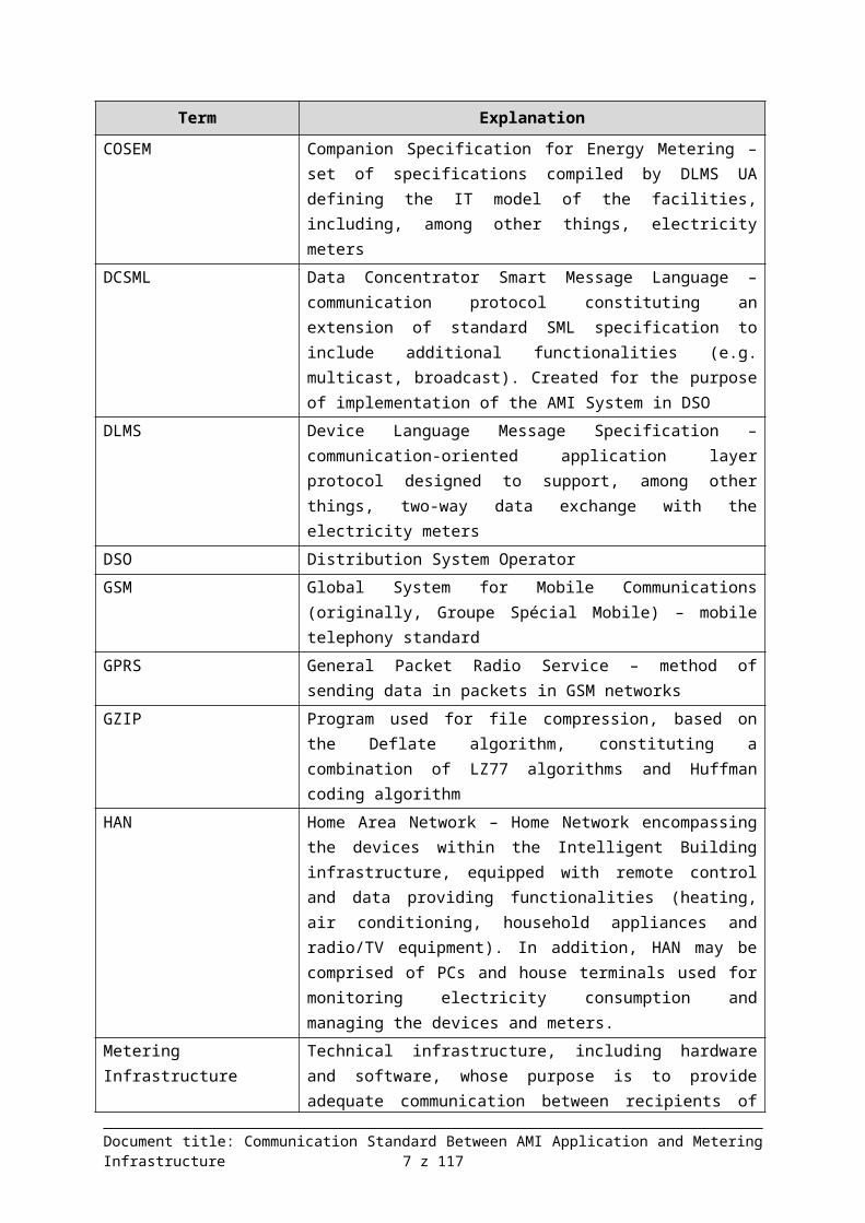
1 Glossary of terms and acronymsTable 1. Glossary of terms and acronyms
Term Explanation
AES Advanced Encryption Standard – symmetric block cipher adopted by the National Institute of Standard and Technology.
AES-GCM 128 Advanced Encryption Standard – Galois/Counter Mode – GCM is a double-functionality cipher and authentication mode. AES performs 10 (128-bit key) substitution-permutation cipher rounds. They consist of preliminary substitution, permutation matrix (mixing of rows, mixing of columns) and modification with 128-bit key.
AMI Advanced Metering Infrastructure.Comprehensive system of meters, communication systems and applications for gathering, storing and analyzing the metering data and managing the metering infrastructure.
APDU Application layer Protocol Data UnitApplication Centralized AMI application – responsible for gathering and
managing the metering dataASN.1 Abstract Syntax Notation One – standard used to describe the
structures designated for representation, coding, transmission and decoding of data
BER Basic Encoding Rules – method of coding the data described by the ASN.1 specification
CA Certification Authority – institution of trust, office of certificationCBP Central Metering DatabaseCAZ Central Managing Application.Certificate Public key and information on the entity's identity signed digitally by
the office of certificationCOSEM Companion Specification for Energy Metering – set of specifications
compiled by DLMS UA defining the IT model of the facilities, including, among other things, electricity meters
DCSML Data Concentrator Smart Message Language – communication protocol constituting an extension of standard SML specification to include additional functionalities (e.g. multicast, broadcast). Created for the purpose of implementation of the AMI System in DSO
DLMS Device Language Message Specification – communication-oriented application layer protocol designed to support, among other things, two-way data exchange with the electricity meters
DSO Distribution System OperatorGSM Global System for Mobile Communications (originally, Groupe
Spécial Mobile) – mobile telephony standardGPRS General Packet Radio Service – method of sending data in packets in
Document title: Communication Standard Between AMI Application and Metering Infrastructure 5 z 94

Term Explanation
GSM networksGZIP Program used for file compression, based on the Deflate algorithm,
constituting a combination of LZ77 algorithms and Huffman coding algorithm
HAN Home Area Network – Home Network encompassing the devices within the Intelligent Building infrastructure, equipped with remote control and data providing functionalities (heating, air conditioning, household appliances and radio/TV equipment). In addition, HAN may be comprised of PCs and house terminals used for monitoring electricity consumption and managing the devices and meters.
Metering Infrastructure Technical infrastructure, including hardware and software, whose purpose is to provide adequate communication between recipients of electricity and DSO, including information on electricity consumption. The Metering Infrastructure connects to the Application System via the Intermediating Infrastructure. The Metering Infrastructure will be comprised of power meters and concentrators as well as other devices connected to them, including HAN devices and meters of other utilities.
KDL Metering Data ConcentratorKDLP Metering Data Concentrator – Program.LE Electricity Meter.LPU Meter Use Case.nN Low voltage.OBIS Object Identification System – system of coding the COSEM model
objects.OSI Open System Interconnection. – standard defined by the ISO and
ITU-T organizations, describing the network communication structure.
PKI Public Key Infrastructure – structure of trust, based on confirmation of authenticity with use of certificates issued by the hierarchy of certification offices.
PLC Power Line Communication/Carrier – communication technique allowing to remotely send the data via the electricity cables.
PRIME PoweRline Intelligent Metering Evolution – open specification defining communication in the lowest layers of the communication system after PLC, from the terminal devices (meters) to the data concentrator located in the medium-voltage/low-voltage transformer station.
SAK Acquisition System.SML Smart Message Language – application layer protocol developed by
the MeKo project group, designated to support, among other things, two-way data exchange with the electricity meters.The MeKo project group is comprised of the following: Dr. Neuhaus Telekommunikation GmbH, E.ON Mitte AG, E.ON Netz GmbH,
Document title: Communication Standard Between AMI Application and Metering Infrastructure 6 z 94
Term Explanation
Emsycon GmbH, EnBW Vertriebs und Servicegesellschaft mbH, Landis+Gyr GmbH, RWE Rhein-Ruhr Netzservice GmbH.
MV Medium voltage.SSH Secure Shell – standard of communication protocols used in the
TCP/IP computer networks, in the client – server architecture. It is used for connecting to the remote computer, and provides encryption and allows authentication of the user by many methods.
S-FSK Spread Frequency Shift Keying – one of the techniques for transmitting the data through the PLC network.
TCP/IP Transmission Control Protocol/Internet Protocol – set of transmission (TCP) and network (IP) layer protocols providing a unified method of sending the data in various types of networks.
TLS/SSL TLS (Transport Layer Security) – extension of the SSL (Secure Socket Layer) protocol, adopted as Internet standard, which aims at providing confidentiality and integrity of data transmission and ensuring authentication; it is based on asymmetric ciphers and certificates of X.509 standard.
WS-RT Web Services Resource Transfer – protocol based on the popular WebServices technology used in case of data exchange between the applications operating in the TCP/IP network, created under the DSMR standard.
xDLMS Extended DLMS – extension of the DLMS protocol to the DLMS/COSEM standard defined by norm IEC 62056-53.
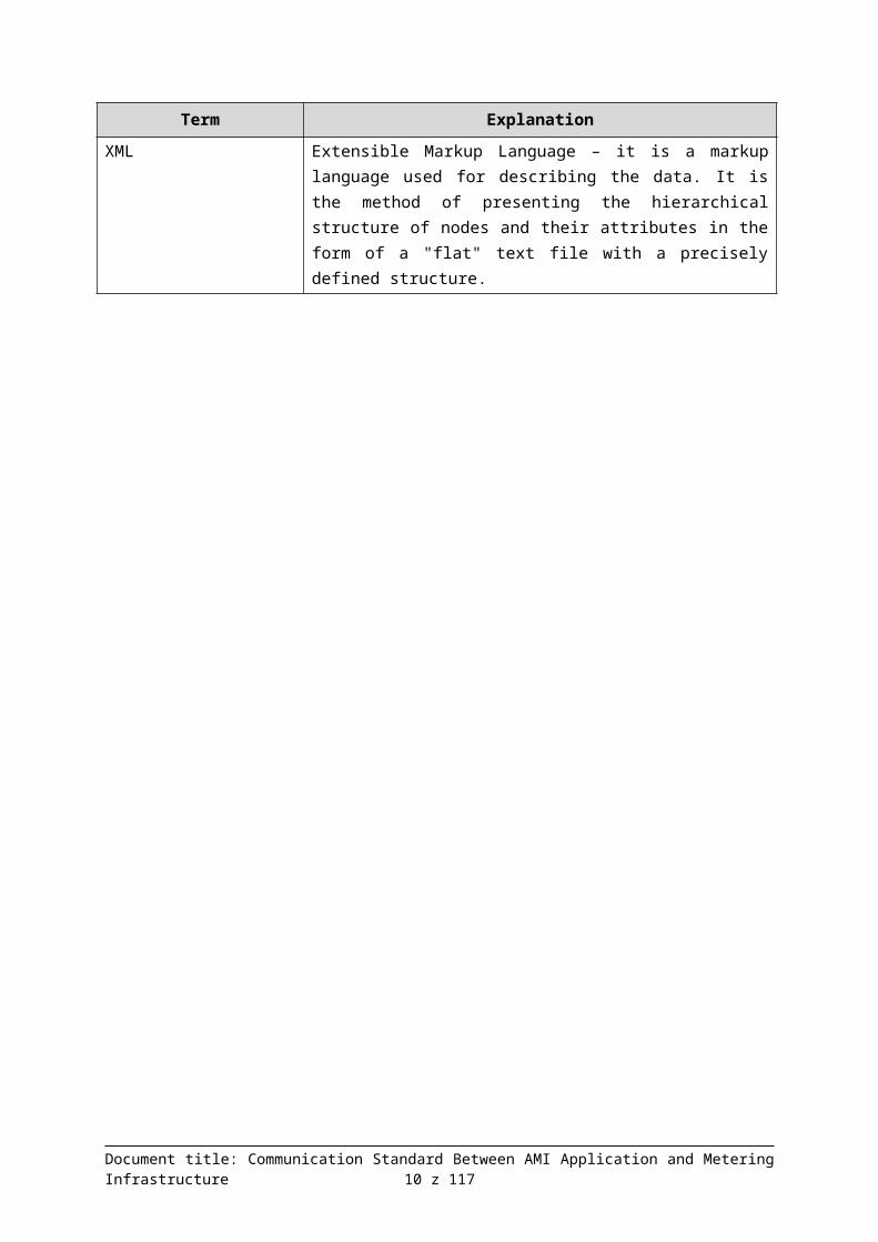
XML Extensible Markup Language – it is a markup language used for describing the data. It is the method of presenting the hierarchical structure of nodes and their attributes in the form of a "flat" text file with a precisely defined structure.
Document title: Communication Standard Between AMI Application and Metering Infrastructure 7 z 94

2 IntroductionThis document is an excerpt from the document entitled "Communication Standard Between the Application and the Metering Infrastructure" (version 2.00).
The document contains the concept and the basic assumptions for the communication standard with a proposed custom DCSML communication protocol created especially for Energa-Operator SA's needs. The standard takes into account the needs and characteristics of the AMI System.
This document presents:
use cases for communication between the Application and the Metering Infrastructure,
description of messages,
grammar of the protocol, examples of queries and responses in DCSML (in the APDU and source form).
Development of the communication standard takes into account the guidelines included in the following document:
[1] Stance of the President of ERA in the matter of requirements for intelligent metering and billing systems implemented by OSD E, taking into account the purpose and the proposed support mechanisms for the postulated market model. ERA 2010. http://www.ure.gov.pl/download.php?s=1&id=4295P1.3 AMI Application. Concept of the Integrated Application System. Central Managing Application. 2011.05
Document title: Communication Standard Between AMI Application and Metering Infrastructure 8 z 94

3 Concept for the communication standard in DSOIn this chapter we have presented the assumptions which were adopted for work on the proposed communication standard, and presented the concept of the standard based on the assumptions adopted.
3.1 Assumptions for the communication standard
3.1.1 General assumptionsThe following general assumptions were adopted:
1. It must ensure sufficient functionality to meet all the requirements of the AMI System in DSO.2. It must be open to all metering devices, not just power meters (natural gas, water, heat
meters).3. It must ensure communication between devices of various manufacturers (which use that
standard).4. It should be precisely defined so as to ensure conducting of tests guaranteeing cooperation
between the devices.5. It must ensure communication between:
a. KDL and SAK – if readings take place through KDL (PLC).b. LE and SAK – if readings are performed directly by SAK (GPRS, GSM, LAN/WAN).
In addition, in order to prevent the path to the author's solution from being closed, it is proposed that the following recommendations are met, however they are not mandatory.
1. The protocol should be regulated by the standards, in order to guarantee its openness and development.
2. Usage of the protocol should be verified through prior large-scale implementations.
3.1.2 Technical assumptionsThe following technical assumptions were adopted:
1. Due to limited throughput of connections between KDL and SAK, it is necessary to:a. minimize the size of the message (queries and responses),b. minimize network traffic between SAK and KDL (type broadcast and multicast
messages).2. KDL is "non-transparent" which means that SAK communicates with KDL in the manner
minimizing the network traffic (see the assumption above), and KDL is responsible for optimal organization of communication with LE.
3. The manner of SAK's communication with LE should be unified regardless of the communication channel used. Accordingly, if the meter does not communicate with the infrastructure through PLC (but through e.g. GPRS) and therefore there will be no KDL between LE and SAK, Program Concentrator will be functionally inserted in KDL's place which will fulfill KDL's functions.
4. SAK has to be able to send to LE the message in the "transparent KDL" mode.5. It is necessary to properly secure the data through the following:
a. authentication,b. authorization and access rights,c. ciphering,d. data integrity (control and error correction mechanisms).
Document title: Communication Standard Between AMI Application and Metering Infrastructure 9 z 94
6. We propose to use open solutions as far as implementation of data security measures is concerned.
7. We propose to use prioritization at the level of lower communication layers as well as the application layer.
3.2 Overall concept of the communication standardCommunication standard should be reviewed in the following areas.
Figure 1. Areas of communication in the AMI system
1. Area I – communication between the SAK system and KDL – communication will be conducted through the connection based on TCP/IP with minimum throughput of 64 kbit/s (in one of two basic communication techniques: PLC MV or WiMax).
2. Area II – communication between KDL and LE – communication will be conducted through connection in PLC technology.
3. Area III – communication between the SAK system and LE – communication will be conducted through the connection based on TCP/IP through GPRS with throughput of 30 – 80 kbit/s.
Document title: Communication Standard Between AMI Application and Metering Infrastructure 10 z 94
COSEM OBJECTS
COSEM OBJECTS

SAK - KDL KDL - LE KDLP - LE
COSEM Application Layer
COSEM Application Layer
COSEM Application Layer
(PLC SN, WiMax, GPRS))
PLC OFDM
DCSML
PN/EN 61334-4-32
Wrapper Layer
UDP
TCP
GPRS, …
DLMS
PRIME MAC
PRIME PHY
DLMS
PLC OFDM
IP IP
TLS
TCP
UDP
Figure 2. Areas of communication in the AMI system – layers of the protocol
3.2.1 Area of communication between SAK and concentrators
We propose development and implementation of language and standard of communication with the concentrator based on structures and solutions used in SML (Smart Message Language). Definition of SML is based on ASN.1 notation which allows to expand basic available functions to include new functionalities which we need. Therefore we propose adaptation of SML for the purposes of this project.
Grouped SML messages (application layer protocol) are sent in the form of binary files-streams in which SML messages are encoded in accordance with ASN.1 to the binary form. Writing format based on XML will not be used because files have large sizes and the time of processing and interpretation of contents of XML files by computer systems is very long.
Due to the fact that the proposed language of communication between SAK and KDL is based on SML, we would like to propose to name that language DCSML – Data Concentrator Smart Message Language.
In the presentation layer for sending DCSML files, TLS or SSL protocol will be used as standard security measure for communication between the Application System and the concentrator. TLS/SSL provide the mechanisms of user authentication and encoding of the sent content on the basis of AES 128 cryptographic algorithm.
3.2.2 Area of communication between concentrators and meters
We propose to use open, normalized communication standards in the layer of communication between KDL and meters. In the physical and data connection layer we recommend to use the PRIME protocol, and in the application layer – we recommend to use the DLMS/COSEM standard.
The PRIME physical layer and data connection layer protocol is adequate because it has the following features:
o it is a well-defined and described standard,o there are several laboratory centers in the world which certify hardware for
compliance with PRIME specification,
Document title: Communication Standard Between AMI Application and Metering Infrastructure 11 z 94
o the standard does not breach patent rights of third parties,o it is a modern solution which is based on the technique of OFDM modulation in the
physical layer; in addition, it is characterized by small markup on the size of transmitted data, control of errors in MAC PDU frames and dynamic adaptation of the network's logical structure for the purpose of optimizing the communication and in the situations involving disruptions and/or damages of individual network nodes (mesh-type networks),
o it provides data transmission security mechanisms.
The DLMS/COSEM application layer protocol is adequate because it has the following properties:
o it is a defined standard which is developed and maintained by DLMS User Association,
o verification of compliance with the standard consists in performance of several tests defined in DLMS User Association's Yellow Book,
o it has a concise format of APDU data packets as compared to other protocols used in metering communication (e.g. IEC1107, IEC61056-21, etc.),
o it provides all the necessary packet security mechanisms (authentication, authorization, ciphering and data integrity),
o it provides description of metering data for various types of utilities supplied (electricity, water, heat, natural gas).
The standard communication technologies recommended for the layer of communication between concentrators and power meters serve the following purposes:
1. Providing replaceability of metering equipment coming from various suppliers on the market, and therefore ensuring independence from a single supplier which could try to dictate its own prices in the future.
2. Eliminating problems related to disruptions in communication with devices operating in various PLC technologies within the same electricity segment.
3. Utilization of knowledge and long experience of manufacturers and associations developing the standard solutions which have been captured in the norms.
3.2.3 Area of communication between SAK and meters
Due to preservation of unified form of communication with concentrators as well as the group of those electricity meters which will be queried directly by the SAK system and because of the TCP/IP communication protocol of the transportation layer, also in this case we are planning to use the DCSML protocol as the application layer protocol in communication between SAK and the program concentrator (KDLP).
For the purpose of unifying communication between SAK and LE i.e. for the purpose of covering with the proposed standards also those LEs which may (or must) communicate with other channel than PLC, it was assumed that in such cases communication would take place via the Program Concentrator (KDLP). The advantage of such solution involves separation of the process of communication with the meters outside of the Acquisition System. It is assumed that at the present time communication takes place through that path in case of approx. 2% of all power meters. However, one cannot be certain that the number of meters which conduct communication in that path will not increase in the future. Moreover, during implementation of metering infrastructure it may turn out that there are locations (geographic areas) in which it will not be possible to use PLC. Separation of Program Concentrator KDLP will make it possible to use larger than assumed quantity of meters. Moreover, there can be
Document title: Communication Standard Between AMI Application and Metering Infrastructure 12 z 94

more than one KDLP in the system in various geographic locations and on many hardware items (workstations).
We propose to use open, normalized communication standards in the layer of communication between KDLP and meters. We recommend to use the complete DLMS/COSEM standard. Due to the fact that GPRS connections with TCP/IP are used, DLMS wrapper captured in the DLMS/COSEM standard should be used in the presentation layer.
3.2.4 Traffic prioritizationThe purpose of broadly understood traffic prioritization is to ensure the option of sending messages with various degree of importance and in different time regimes, so that transmission of less important messages would not block more important ones.
Before describing rules and execution of traffic prioritization, the assumptions for the executed (and therefore prioritized) Tasks were given.
3.2.4.1 TasksThe following assumptions concerning the Tasks were accepted:
1. The Tasks have the following characteristics:a. they may include one or several activities,b. if the tasks include several activities, the sequence of their performance should be
specified,c. the tasks may be addressed to one, many (multicast) or all (broadcast) meters.
2. The Task may be ordered by CAZ to SAK in the following way:a. instruction to perform the task issued on one-off basis to one or several meters (to be
performed immediately or in the future)b. instruction, issued to one or several meters on one-off basis, to perform cyclical task
(e.g. daily subscription)3. The main attributes of single task are as follows:
a. priority: standard, high, critical (standard priority is accepted as default),b. manner of execution:
i. single communication session: PULL (intended for execution of short tasks within a single meter e.g. switch off the contactor).[See Figure 3]
ii. two communication sessions: PULL + PULL (intended for execution of complex tasks, assuming that it will be decided that SAK will read the results); the first session includes sending the task to KDL, the second – sending the results to SAK. [See Figure 4]
iii. two communication sessions: PULL + PUSH (intended for execution of complex tasks, assuming that it will be decided that KDL will read the results); the first session includes sending the task to KDL, the second – sending the results to SAK. This method is the basic method used in mass readout of data from LE. [See Figure 5]
iv. single communication session: PUSH (for readout of event data concerning emergency situations). [See Figure 6]
Document title: Communication Standard Between AMI Application and Metering Infrastructure 13 z 94

sd PULL
SAK
(from SAK Actors)
KDL
(from SAK Actors)
LE
(from SAK Actors)
Get data()
ack()
Get data()
Send data()
Send data()
ack + disconnect()
sd PULL PULL
SAK
(from SAK Actors)
KDL
(from SAK Actors)
LE
(from SAK Actors)
Get data()
ack + disconnect()
Get data()
Send data()
Get data()
Send data()
ack + disconnect()
Figure 3: Diagram of the sequence – single communication session PULL
Figure 4: Diagram of the sequence – two communication sessions PULL + PULL
Document title: Communication Standard Between AMI Application and Metering Infrastructure 14 z 94

sd PULL PUSH
SAK
(from SAK Actors)
KDL
(from SAK Actors)
LE
(from SAK Actors)
Get data()
ack + disconnect()
Get data()
Send data()
Send data()
ack + disconnect()
sd PUSH
SAK
(from SAK Actors)
KDL
(from SAK Actors)
LE
(from SAK Actors)
ALARM()
ALARM()
ack + disconnect()
Figure 5: Diagram of the sequence – two communication sessions PULL + PUSH
Figure 6: Diagram of the sequence – single communication session PUSH
4. Configuration of the manner of executing the tasks will take place on the side of the CAZ system, with reservation that only system Administrator will have access to configuration of the manner of executing the task (p. 3b) and the users will only choose specific tasks from the available, previously configured list.
3.2.4.2 Prioritization rulesThe following options for parameterization of priorities were specified as part of data exchange process:
1. Priority on the level of SAK-KDL communication and processing by KDL (KDL-LE communication)
2. QoS for data on the TCP/IP level
Priority on the level of SAK-KDL communication allows to determine which tasks on the central level concerning communication with Concentrators and Meters will be processed firstly. Priority also allows to determine which tasks related to communication with the individual meters should be performed by KDL firstly.
Document title: Communication Standard Between AMI Application and Metering Infrastructure 15 z 94

QoS for data on the TCP/IP level is a recommendation for communication sessions (provided that this mechanism is supported by the concentrator) which are initiated by the Concentrators for the purpose of sending the results to SAK. Contrary to the possibility of queuing tasks in SAK, such option is not available if transmission is initiated in the opposite direction (KDLSAK), therefore if priorities are assigned at the data packet (QoS) level, the results of tasks specified as urgent will be delivered and they will be processed further by SAK with first priority.
Priorities may accept the following values:
1. Standard, in normal mode for the flow of typical information for which no high time regimes have been set
2. High, for the flow of information with high degree of importance which should be delivered promptly
3. Critical, for the flow of information with the highest degree of importance e.g. for the purpose of voiding the performance of high priority tasks – to be used in specific cases.
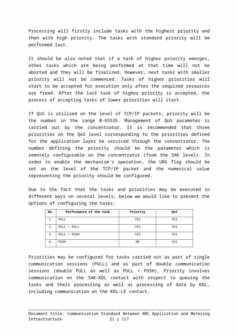
Processing will firstly include tasks with the highest priority and then with high priority. The tasks with standard priority will be performed last.
It should be also noted that if a task of higher priority emerges, other tasks which are being performed at that time will not be aborted and they will be finalized. However, next tasks with smaller priority will not be commenced. Tasks of higher priorities will start to be accepted for execution only after the required resources are freed. After the last task of higher priority is accepted, the process of accepting tasks of lower priorities will start.
If QoS is utilized on the level of TCP/IP packets, priority will be the number in the range 0-65535. Management of QoS parameter is carried out by the concentrator. It is recommended that three priorities on the QoS level corresponding to the priorities defined for the application layer be serviced through the concentrator. The number defining the priority should be the parameter which is remotely configurable on the concentrator (from the SAK level). In order to enable the mechanism's operation, the URG flag should be set on the level of the TCP/IP packet and the numerical value representing the priority should be configured.
Due to the fact that the tasks and priorities may be executed in different ways on several levels, below we would like to present the options of configuring the tasks:
No. Performance of the task Priority QoS
1. PULL YES YES
2. PULL + PULL YES YES
3. PULL + PUSH YES YES
4. PUSH NO YES
Priorities may be configured for tasks carried out as part of single communication sessions (PULL) and as part of double communication sessions (double PULL as well as PULL + PUSH). Priority involves communication on the SAK-KDL contact with respect to queuing the tasks and their processing as well as processing of data by KDL, including communication on the KDL-LE contact.The priority cannot be configured for transmission of emergency events in the PUSH mode because due to high importance of the events, these tasks are processed by SAK with first priority.
Document title: Communication Standard Between AMI Application and Metering Infrastructure 16 z 94

In order to enable the execution of prioritization mechanisms, it is recommended to implement the following mechanisms on the Concentrators:
1. Parallel handling of TCP/IP session on the level of communication between SAK and KDL should be implemented on the concentrator.
2. If it receives another parallel task (SAK-KDL session of higher priority), the Concentrator should freeze the execution of current tasks with lower priority until the task of higher priority is finalized.
3. In case of another parallel SAK-KDL session with the same priority, the concentrator should enable parallel processing of all tasks with the same priority.
4. If several SAK-KDL sessions appear, where one of them will have a higher priority than the others, the tasks of other sessions with lower priority should be put on hold until the performance of the task of higher priority session is finalized.
5. If the Concentrator stops the performance of the task, it should finalize the performance of atomic operation on the level of the PLC network e.g. readout of a single parameter from the given Meter, before beginning to perform the activities as part of a different task of higher priority.
6. In case of performance of tasks as part of individual communication sessions, the appearance of another task of higher priority should not stop the performance of that first task so as not to stop the unnecessarily initiated SAK-KDL session. The tasks which are stopped should be only the ones which are performed as part of double communication sessions (order + results readout).
In case of direct communication between SAK and the meters, communication will take place through the program concentrator and the above-described rules for the case of communication SAK – Concentrator – Meter will be applied.
3.2.5 Digital signaturesMeans of securing the SAK-KDL communication involve the TLS/SSL mechanism based on the keys of the PKI infrastructure. CA should be provided by IT DSO services.
3.2.6 Concept of transport
I. Transport of data on the Acquisition Server – Concentrator path
The DCSML (Data Concentrator Smart Message Language) protocol, which is the modification of SML from the standpoint of optimization of processing for the needs of implementation of the AMI system in DSO, was used for exchange of data in the application layer.
The protocol enables flexible definition of queries and responses to such queries. It is a platform for exchange of data in the standardized manner on the Acquisition Server – Concentrator path. The data i.e. the tasks as well as the results are formed into APDU elementary binary units which are designated for sending in a unified form from the Acquisition Server (SAK) to the Concentrator (KDL) or in the opposite direction.
As part of the session layer of the ISO OSI model, the TLS/SSL protocol with the AES algorithm was used as the data stream layer, as well as authentication with public and private keys. The process of setting up a connection is as follows:
Document title: Communication Standard Between AMI Application and Metering Infrastructure 17 z 94

1. Connecting the Acquisition Server with the Concentrator on the level of TCP/IP sockets on the specified port.
2. Authentication:a. AMI server initiates connection with the concentrator and sends a random numberb. Concentrator sends its certificate (public key) and a random number to the serverc. AMI server sends its certificate (public key) to the concentratord. AMI server generates the session key (used in ciphering of AES), ciphers it with the
concentrator's public key and sends it to the concentratore. AMI server signs the previously mentioned random numbers with its own private keyf. Concentrator deciphers the session key with its own private key (the fact of having the
deciphered session key i.e., in consequence, having the private key consistent with the public key, is the proof of the concentrator's identity)
g. Concentrator verifies the signature sent by AMI server against the server's public key (correctness of the signature is the proof that the AMI server has a private key consistent with the public key i.e. confirms the server's identity)
h. The authenticated parties commence the transmission of data with use of the AES algorithm and the key mentioned in item 4.
i. If there is an error in authentication (e.g. incorrect keys), the Acquisition Server and the Concentrator will immediately break the connection at the TCP/IP level.
3. Setting up the ciphered transmission session on the basis of the symmetric key and conducting cyclical dialog:
a. Acquisition Server sends a demand in the form of APDU data packet,b. Concentrator sends a response in the form of APDU data packet,c. Transmission session is closed.
It is possible to optimize the authentication process by removing the need to each time exchange the public keys (they are stored locally on the side of SAK and KDL), provided that it is technically possible to carry out such algorithm.
II. Transport of events on the Concentrator – Acquisition Server path
In the application as well as transportation layer, the two-way communication is symmetric. Communication takes place through the DCSML protocol (described in chapter ), secured by TLS/SSL protocol.
Due to the fact that events are asynchronous, it is possible that there will be a large number of attempts to make a connection during a short period of time. Load balancer will be used on the side of the acquisition server, whose tasks will include distribution of load between the individual nodes of the SAK cluster which will independently process the reported events.
The presence of many SAK nodes and distribution of load are not important to the Concentrator from the point of view of communication. Concentrator makes a connection to the previously defined address of the Acquisition Server as if it were a single server.
III. Requirements of the network infrastructure
Communication between Acquisition Servers and Concentrators takes place at the level of TCP/IP. In order to ensure that the concentrator or meter will be addressed unequivocally (in case of 2% of meters with which communication will be conducted directly), it will be necessary to assign them with unique IP addresses in the global scale of the DSO network. There are two options of assigning IP addresses – statically and dynamically. The first method assumes manual configuration of network parameters on
Document title: Communication Standard Between AMI Application and Metering Infrastructure 18 z 94

the concentrators before their installation in the field. The second one assumes using DHCP servers for automatically assigning the IP addresses and other network configuration parameters.
Due to large scale of the undertaking and the fact that it will be necessary to configure approx. 60 thousand Concentrators, there exists the risk of occurrence of significant percentage of incorrect configurations resulting from human errors. Therefore it is also recommended to automatically assign the IP addresses via the DHCP servers.
1. Fulfillment of the following requirements will ensure departure from manual configuration of IP addresses of the Concentrators on the assembly tables in favor of automatic configuration: assigning the concentrators with IP addresses by DHCP servers from the global address pool intended for the metering equipment. The global address pool is understood as the pool of addresses dedicated to the metering infrastructure within the DSO network, however this does not mean that it will be necessary to use the fragment of the Internet global address pool.
2. Automatic reservation of IP addresses for each MAC address of the concentrator (or the meter from the 2% pool) so that such address would be the same in case of next requests to assign the IP address sent by the same device.
3. Storing the reservations of addresses for 90 days if there is no activity of the devices. Only if the devices are inactive for a longer period of time the IP address may be released and assigned to a different concentrator (or the meter from the 2% pool)
4. Synchronization of reservations of IP addresses between the DHCP servers in such way so as to ensure that unique addresses are assigned to the individual devices. Or possibly using a single DHCP central server for the entire metering network.
Details of network infrastructure management policy must be consistent with DSO's corporate policy in that regard.
Document title: Communication Standard Between AMI Application and Metering Infrastructure 19 z 94

4 Meter Use CasesIn this chapter we presented the results of analytical work associated with the defined cases of usage of the Metering Infrastructure.The list of Meter Use Cases was compiled.For each case, the messages and other data exchanged between SAK, KDL and LE were analyzed.On the basis of the results of this analysis, the syntax of DCSML was developed i.e. a set of messages which should be sufficient for servicing all the identified Meter Use Cases (LPU).
4.1 Categories, Identifiers and Statuses of Meter Use CasesThe table below presents categories which were defined for Meter Use Cases.
Table 2. Categories of Meter Use Cases
Code Name DescriptionI Installation LPUs for installation and deinstallation of KDL and LE, exchanges,
software updates, etc.
K Configuration LPUs related to configuration of KDL and LE.
O Readout LPUs for readouts of metering data.
S Control LPUs requiring that requests controlling the devices' operation be sent to LE and/or KDL.
Z Notification LPUs executed through alarm being reported by LE and KDL. This category was highlighted because LPUs related to it require special flow of messages between the devices.
The following was assigned to each LPU:
Identifier, Category, Status.
The identifier has the following structure: LPUnna, where:
LPU is constant, nn is a number (with a zero which does not have the meaning); due to the fact that the list will
be updated, LPUs may be removed from it, hence the nn numbers do not necessarily have to be the subsequent numbers,
a is a small letter (optional) which makes it possible to insert new LPUs in the logical sequence between the already existing LPUs.
Statuses may have the following values:
A – active LPU, to be serviced in the first version of DCSML, B – LPU to be serviced in the future, W – doubtful LPU, a decision as to its existence should be made in the course of further
analytical work, X – voided LPU, logically removed from the LPU list; it is not physically removed from the
list so as to prevent its identifier from being used once again which could lead to confusion.
Document title: Communication Standard Between AMI Application and Metering Infrastructure 20 z 94
In the later analysis related to DCSML project, only LPUs with "A" status were taken into account.
4.2 List of Meter Use CasesThe table below contains the list of LPUs with "A" status.
Table 3. Meter Use Cases with "A" status.
ID NameLPU01 Installation of new LE, reporting of LE after power failureLPU02 Installation of new KDLLPU03 No communication with LELPU04 KDL Shutdown/FailureLPU05 Update of LE's softwareLPU06 Update of KDL's softwareLPU07 LE configurationLPU08 KDL configurationLPU09 Definition of subscriptionLPU10 Readout of LE registersLPU11 Readout of configurations and data from KDLLPU12 Execution of subscriptionLPU13 Readout of LE configurationLPU14 Verification of connection with LELPU15 Verification of connection with KDLLPU16 Direct communication with LE (transparent concentrator mode)LPU17 Restart of KDLLPU18 Reporting of alarm by LELPU19 Reporting of alarm by KDLLPU20 LE time synchronization / change
The full list of Meter Use Cases – with specification of the Category – is contained in Appendix no. 2 to this document in "LPU" Sheet.
4.3 Analysis of Meter Use CasesThe following was specified for each LPU:
1. Scope.2. Exchanged data and messages (sequence diagrams).
On the sequence diagrams, the exchange of data between SAK and KDL was described with the proposed DCSML messages. Under the diagrams, the descriptions of the individual flows were placed, where the subsequent points correspond to the subsequent flows labeled with point numbers.
The following rules of communication between SAK and KDL were adopted:
1. The key objective to be achieved is the minimization of data flows with simultaneous minimization of waiting time for replies from LE.
Document title: Communication Standard Between AMI Application and Metering Infrastructure 21 z 94

2. It has been assumed that, by principle, data will be transferred from KDL to SAK immediately after their completion in KDL. For this purpose, the "push" method will be used i.e. sending the data from KDL to SAK without waiting for request from SAK.
3. It will be possible to perform readouts of data from LE using the "pull" mode. Enforcement of the "pull" mode will be possible:
a. at the level of a single Task involving readout of data from LE – in such case, the Task will be provided with the "execution in the pull mode" attribute,
b. at the KDL level – in such case, the "execute the Tasks involving readout of data from LE in the pull mode" value will be set in KDL's configuration parameters,
c. at the SAK level – in such case, all the Tasks involving readout of data from LE will be provided with the "execution in the pull mode" attribute,
d. at the Subscription level – in such case, all the Tasks involving readout of data from LE generated by KDL as part of Subscription will be provided with the "execution in the pull mode" attribute.
4. In the KDL configuration, the maximum waiting time for completing a response from LE will be defined. After this time is exceeded, KDL will transfer the data collected by that moment to SAK – regardless of how many LEs responded by that moment.
5. After receiving a reply from KDL, SAK will verify the completeness of the data received. If they are incomplete, it will take proper actions such as verification of LE's status in CAZ (on the basis of data from SID), checking the connection with LE or once again asking for the missing data.
6. In the subscription mode, KDL is the initiator of tasks in the subsequent cycles. Information on subscription requests is recorded in SAK and KDL so that SAK would be able to control whether the maximum time for sending the data by KDL has not been exceeded.
7. It has been assumed that LE may be seen by only one KDL. The situation in which the same LE is reported by different KDLs will be considered erroneous and it should be reported with critical priority to CAZ.
8. Tasks related to readout of data from LE, configuration and replacement of LE's firmware may be addressed to:
a. a single LE,b. many LEs (multicast),c. all the LEs (broadcast).
Note: The objective of the conducted analysis was to develop a language of communication between SAK and KDL. For this reason, the sequence diagrams pertain only to communication between SAK and a single KDL and the meters serviced by that KDL. This analysis does not cover the method of generating the type multicast and broadcast DCSML commands aimed at individual KDLs on the basis of orders received by SAK from the Central Managing Application.
The sequence diagrams for the individual Meter Use Cases presented in the later part of the document should be treated as proposed method of exchanging the data between the individual LPU actors. In reality, details concerning the sequence as well as the exchanged data will depend on specific solutions of the individual manufacturers as well as the results of further analytical and design work.
Document title: Communication Standard Between AMI Application and Metering Infrastructure 22 z 94

uc Installation Category
LPU01 Installation of new LE,
reporting of LE after failure
LPU02 Installationof new KDL
LPU03 Nocommunication with LE
LPU04 Shutdown / Failure of
KDL
LPU05 Updateof LE software
LPU06 Updateof KDL software
4.3.1 Installation Category
The below diagram presents the Meter Use Cases in Installation Category.
Figure 7. LPU in Installation Category
Document title: Communication Standard Between AMI Application and Metering Infrastructure 23 z 94

sd LPU01 Installation of new LE, reporting of LE after power failure
SAK
(from LPU Actors)
KDL
(from LPU Actors)
LEn
(from LPU Actors)
CAZ
(from LPU Actors)
KDL2
(from LPU Actors)
1. Reporting of LE()
2. Checking whether LE is in the routing table()
3. DCAttentionResponse()
4. Checking whether LE is in the routing table of a different KDL()
5. DCAttentionRequest()
5. DCAttentionResponse()
6. High priority alarm ()
7. DCAttentionResponse()
8. DCAttentionRequestt()
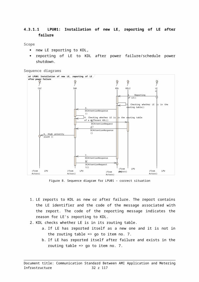
4.3.1.1 LPU01: Installation of new LE, reporting of LE after failure
Scope new LE reporting to KDL, reporting of LE to KDL after power failure/schedule power shutdown.
Sequence diagrams
Figure 8. Sequence diagram for LPU01 – correct situation
1. LE reports to KDL as new or after failure. The report contains the LE identifier and the code of the message associated with the report. The code of the reporting message indicates the reason for LE's reporting to KDL.
2. KDL checks whether LE is in its routing table.a. If LE has reported itself as a new one and it is not in the routing table => go to item
no. 7.b. If LE has reported itself after failure and exists in the routing table => go to item no.
7.3. KDL sends to SAK the information on the report from LE and the problem related to it.4. SAK checks whether the new LE is in the routing table of a different KDL.5. If LE is in the routing table of a different KDL, then SAK queries this KDL to make sure that
LE is accessible from two KDLs.6. If such situation occurs, then SAK will send a high priority alarm to CAZ.7. KDL notifies SAK that LE has reported to it.8. SAK sends to KDL the confirmation of data receipt.
Document title: Communication Standard Between AMI Application and Metering Infrastructure 24 z 94

sd LPU02 Installation of new KDL
SAK
(from LPU Actors)
KDL
(from LPU Actors)
LE1
(from LPU Actors)
CAZ
(from LPU Actors)
1. DCGetParamResponse()
2. Info on reporting of KDL()
3. DCAttentionRequest()
sd LPU03 No communication with LE
SAK
(from LPU Actors)
KDL
(from LPU Actors)
LE1
(from LPU Actors)
CAZ
(from LPU Actors)
1. DCAttentionResponse()
2. Checking the LE status()
2. Checking the LE status()
3. DCAttentionRequest()
If a new LE reports, CAZ will make a decision as regards the readout and the scope of read data.
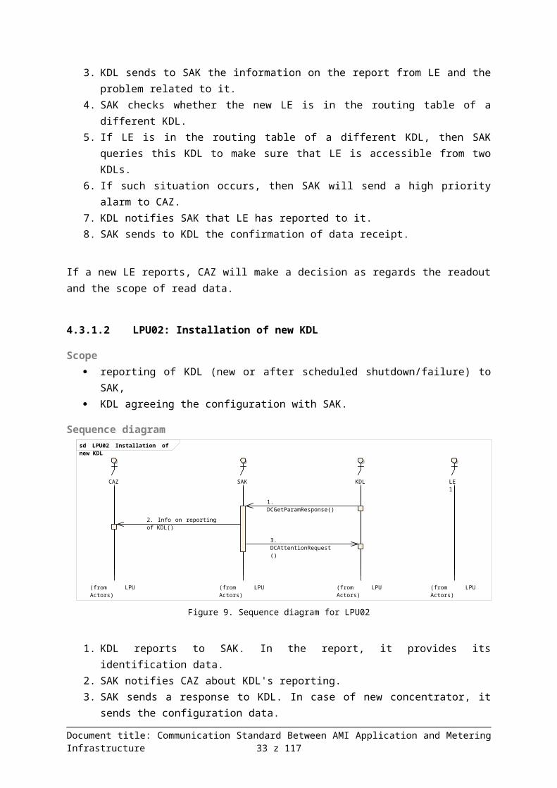
4.3.1.2 LPU02: Installation of new KDL
Scope reporting of KDL (new or after scheduled shutdown/failure) to SAK, KDL agreeing the configuration with SAK.
Sequence diagram
Figure 9. Sequence diagram for LPU02
1. KDL reports to SAK. In the report, it provides its identification data.2. SAK notifies CAZ about KDL's reporting.3. SAK sends a response to KDL. In case of new concentrator, it sends the configuration data.
4.3.1.3 LPU03: No communication with LE
Scope deinstallation of LE, emergency situations causing loss of connection to LE.
Sequence diagram
Figure 10. Sequence diagram for LPU03
Document title: Communication Standard Between AMI Application and Metering Infrastructure 25 z 94
sd LPU04 Shutdown / Failure of KDL – servicing mode
SAK
(from LPU Actors)
KDL
(from LPU Actors)
LE1
(from LPU Actors)
1. Servicing mode()
2. DCAttentionResponse()
3. DCAttentionRequest()
4. Shutdown()
1. KDL identifies LE as problematic (no communication). Sends to SAK the notification about that fact, stating the data of the problematic LE.
2. SAK checks the LE status in CAZ (on the basis of data from SID).3. SAK sends to KDL the information concerning the problematic LE. LE could have been
switched off, taken down, etc. – in such case KDL ends the attempts to initiate communication with that LE.
CAZ makes a decision with regard to strategy for further communication.
4.3.1.4 LPU04: KDL Shutdown/Failure
Scope Service (the following scenario is conditioned on KDL having adequate functionality):
o the fitter changes KDL's status to "under servicing" through a local interface,o a notification is sent to SAK about the fact that KDL's status has been changed to
"under servicing" which may trigger KDL to perform readout of all the data that have not yet been read (see LPU11),
o KDL's operating system is closed,o after the message of completion of the closing process (local), the disassembly or
servicing will take place,o after completion of service and restart, KDL will inform SAK that it is active (see
LPU02). Failure: An emergency situation, failure of the concentrator hardware preventing the
functioning of the operating system, KDL service which does not have the above-described functionality, failure of the channel of communication with KDL;
o failure of KDL or shutdown of the concentrator by the technician,o SAK makes an attempt to reinstate communication (parameter of time and number of
attempts),o SAK checks KDL's status in CAZ (on the basis of data from SID),o if there is no information in CAZ about scheduled servicing of KDL, it will change
the channel to backup – provided that it is available; after the specified time, it will report the failure to CAZ,
Sequence diagrams
Figure 11. Sequence diagram for LPU04 – servicing mode
Document title: Communication Standard Between AMI Application and Metering Infrastructure 26 z 94

sd LPU04 Shutdown / Failure of KDL – without servicing mode
SAK
(from LPU Actors)
KDL
(from LPU Actors)
LE1
(from LPU Actors)
CAZ
(from LPU Actors)
1. Failure or shutdown()
2. DCGetParamRequest()
3. Checking KDL status()
3. Checking KDL status()
4. DCGetParamRequest()
5. Sending information on the problem()
1. The fitter changes KDL's status to "under servicing" through a local interface. It waits for a response from KDL confirming that the process of informing SAK about the planned interruption has been completed.
2. KDL informs SAK that there will be interruption in communication.3. SAK confirms the receipt of this information.4. The fitter disassembles KDL or performs service tasks.
Figure 12. Sequence diagram for LPU04 – without servicing mode
1. Failure of KDL occurs or it is switched off by the fitter.2. SAK ascertains lack of communication. Attempts to make a connection to KDL –
unsuccessfully.3. SAK checks the KDL status in CAZ (on the basis of data from SID).4. If there is no information in CAZ about the scheduled service and the backup channel of
communication with KDL has been determined, SAK will try to initiate a connection through that channel.
5. If attempts to make a connection are unsuccessful, SAK will inform CAZ about situation which has occurred.
4.3.1.5 LPU05: Update of LE's software
Scope setting up the software image in KDL and issuing an instruction through SAK to KDL to
replace software in LE, specifying the moment of switching to new software, transferring software to the meter, setting up the moment of switching to new software
version, confirmation of execution.
Document title: Communication Standard Between AMI Application and Metering Infrastructure 27 z 94

sd LPU05 LE software update
SAK
(from LPU Actors)
KDL
(from LPU Actors)
LE1
(from LPU Actors)
LE2
(from LPU Actors)
LEn
(from LPU Actors)
1. DCMeterFirmwareRequest()
2. DCAttentionResponse()
3. Sending the software()
3. Sending the software ()
3. Sending the software ()
4. Software receipt confirmation ()
4. Software receipt confirmation ()
4. Software receipt confirmation ()
5. DCMeterAttentionResponse()
6. Update confirmation()
6. Update confirmation ()
6. Update confirmation ()
7. DCMeterAttentionResponse()
Sequence diagram
Figure 13. Sequence diagram for LPU05
1. SAK sends to KDL the software image for LE, specifying the time of update.2. KDL sends to SAK the confirmation of receipt of software image.3. KDL sends the software image to LE, specifying the time of update. The following activities
are performed for all LEs to which the new software was sent.4. LE sends to KDL the confirmation of receipt of software image.5. KDL sends to SAK the confirmation of receipt of software image through individual LEs.6. In the designated time, LE performs software update and notifies KDL about this fact, while at
the same time sends the identifier of the installed software version.7. KDL informs SAK about the fact that software has been updated in the individual LEs, stating
the identifiers of the installed software versions.
4.3.1.6 LPU06: Update of KDL's software
Scope setting up the software image in KDL and issuing an instruction through SAK to KDL to
replace software, specifying the moment of switching to new software, confirmation of execution.
Sequence diagram
Document title: Communication Standard Between AMI Application and Metering Infrastructure 28 z 94

sd LPU06 KDL software update
SAK
(from LPU Actors)
KDL
(from LPU Actors)
LE1
(from LPU Actors)
1. DCFirmwareRequest()
2. DCAttentionResponse()
3. Software update()
4. DCGetParamResponse()
Figure 14. Sequence diagram for LPU06
1. SAK sends the software image to KDL, specifying the time of update.2. KDL sends to SAK the confirmation of receipt of software image.3. KDL performs update of its software and works on the new software starting from the
specified moment.4. KDL sends the identifier of the installed software version to SAK.
Document title: Communication Standard Between AMI Application and Metering Infrastructure 29 z 94

uc Configuration Category
LPU07 Configuration ofLE
LPU08 Configuration ofKDL
LPU09 Definitionof subscription
LPU20 Synchronization / change of LE time
4.3.2 Configuration CategoryThe below diagram presents the Meter Use Cases in Configuration Category.
Figure 15. LPU in Configuration Category
4.3.2.1 LPU07: LE configuration
Scope Change of LE configuration parameters:
o calendar (zones),o limitation of power,o change of contactor status (switching it off, securing it),o synchronizing or setting the timeo defining the moment of registering the data in profiles/archives,o defining the structure of complex registers (profiles, archives),o displaying the message on the LE display,o sending the message to HAN,o other.
Document title: Communication Standard Between AMI Application and Metering Infrastructure 30 z 94

sd LPU07 LE configuration
SAK
(from LPU Actors)
KDL
(from LPU Actors)
LE1
(from LPU Actors)
LE2
(from LPU Actors)
LEn
(from LPU Actors)
1. DCMeterSetParamRequest()
2. Configuration change request()
2. Configuration change request ()
3. Request execution/acceptance confirmation()
3. Request execution/acceptance confirmation ()
4. DCMeterAttentionResponse()
5. New configuration activation()
5. New configuration activation()
Sequence diagram
Figure 16. Sequence diagram for LPU07
1. SAK sends to KDL the request to set specific parameters in LE. The request may contain the moment as of which the new parameters are to go into effect.
2. KDL generates the parameterization request for all LEs stated in the request sent by SAK.3. LE confirms the execution of the request (or its acceptance – if the moment as of which the
new parameters are to go into effect has been set).4. After receiving confirmations from all LEs, KDL will confirm to SAK that the data have been
transferred.5. If the moment as of which the new parameters are to go into effect has been set, LE will
activate the new configuration at the moment defined in the request (the new data will begin to prevail as at that moment).
Usually after LPU07, LPU13 "Readout of LE configuration" will be performed for the purpose of verifying whether the new configuration has been successfully installed in LE. The decision as to conducting the readout will be made by CAZ.
4.3.2.2 LPU08: KDL configuration
Scope change
o of maximum waiting time for responses from LE,o of concentrator time (forcing synchronization of time with the use of NTP),o of the method of performing the readouts ("push" mode or "pull" mode),o of other concentrator parameters.
Synchronization of KDL's time with SAK's time will be carried out with use of NTP mechanisms. If this protocol is not implemented in KDL, an alternative algorithm will be executed.
Document title: Communication Standard Between AMI Application and Metering Infrastructure 31 z 94
sd LPU08 KDL configuration
SAK
(from LPU Actors)
KDL
(from LPU Actors)
LE1
(from LPU Actors)
1. DCSetParamRequest()
2. DCAttentionResponse()
3. New data activation()
Sequence diagram
Figure 17. Sequence diagram for LPU08
1. SAK sends to KDL the request to set specific parameters. The request may contain the moment as of which the new parameters are to go into effect.
2. KDL confirms the execution of the request (or its acceptance – if they are to go into effect as of the specified moment).
3. If the moment as of which the new parameters are to go into effect has been set: It will activate the new configuration at the moment specified in KDL's request.
Usually after LPU08, LPU11 "Readout of configurations and data from KDL" will be performed for the purpose of verifying whether the change of configuration was successful.
4.3.2.3 LPU09: Definition of subscriptionSubscription has the following basic attributes:
identifier, scope of delivered data, frequency and schedule of data registration (from LE to KDL), frequency and schedule of data delivery (from KDL to SAK), obligation start time, obligation end time.
Subscription may be assigned to one LE, many LEs (multicast) or to all LEs (broadcast).
ScopeIncludes:
creation of new subscription definition, change of subscription definition, deactivation of subscription, removal of subscription.
Execution of actions defined by the subscription is covered by LPU12.
Document title: Communication Standard Between AMI Application and Metering Infrastructure 32 z 94
sd LPU09 Subscription Definition
SAK
(from LPU Actors)
KDL
(from LPU Actors)
LE1
(from LPU Actors)
1. DCSubscribeRequest()
2. DAttentionResponse()
sd LPU20 LE time synchronization / change
CAZ
(from LPU Actors)
SAK
(from LPU Actors)
LE1
(from LPU Actors)
KDL
(from LPU Actors)
1. DCMeterSetParamRequest()
2. LE time readout()
2. LE time()
3. Calculation of departure of LE time from KDL time()
4. DCMeterAttentionResponse()
5. Info on departure greater than permitted ()
6. Setting the time()
7. Confirmation of setting the time()
8. DCMeterAttentionResponse()
Sequence diagram
Figure 18. Sequence diagram for LPU09
1. New subscription is configured in SAK, and then proper definition is sent to KDL. Configuration may consist in creating the new definition, change of definition's parameters (e.g. LE lists for which that definition prevails), deactivation or permanent removal of the definition.
2. Definition is configured in KDL. KDL sends the confirmation of subscription configuration to SAK.
Execution of subscription is described in use case LPU12.
4.3.2.4 LPU20: LE time synchronization / change
Scope LE time synchronization setting the LE time
Sequence diagram
Figure 19. Sequence diagram for LPU20
Document title: Communication Standard Between AMI Application and Metering Infrastructure 33 z 94

uc Readouts Category
LPU10 Readoutfrom LE registers
LPU11 Readout of data fromKDL
LPU14 Checkingconnection with LE
LPU15 Checkingconnection with KDL
LPU13 Readoutof LE configuration
1. SAK initiates LE time synchronization / change.2. KDL reads LE time.3. KDL calculates difference between LE time and KDL time.
a. the difference is smaller or equal than the set permissible time difference (KDL parameter). Go to item 4.
b. the time difference is greater than the set permissible time difference. Go to item 6.4. KDL informs SAK about greater than permissible time difference.5. SAK informs CAZ about greater than permissible time difference.6. KDL sets the LE time.7. LE confirms that the time has been set.8. KDL sends the confirmation to SAK that the order of time synchronization / change has been
executed.
4.3.3 Readouts CategoryThe below diagram presents the map of Meter Use Cases in Readouts Category.
Figure 20. LPU in Readouts Category
4.3.3.1 LPU10: Readout of data from LE
Scope Readout of metering data and non-metering data.
Document title: Communication Standard Between AMI Application and Metering Infrastructure 34 z 94

sd LPU10 Readout of LE registers - "push" mode
SAK
(from LPU Actors)
KDL
(from LPU Actors)
LE1
(from LPU Actors)
LE2
(from LPU Actors)
LEn
(from LPU Actors)
1. DCMeterGetDataRequest()
2. DCAttentionResponse()
3. Data request()
4. Sending the requested data()
3. Data request ()
4. Sending the requested data ()
5. DCMeterGetDataResponse()
6. DCAttentionRequest()
sd LPU10 Readout of LE registers - "pull" mode
SAK
(from LPU Actors)
KDL
(from LPU Actors)
LE1
(from LPU Actors)
LE2
(from LPU Actors)
LEn
(from LPU Actors)
1. DCMeterGetDataRequest()
2. DCAttentionResponse()
3. Data request ()
4. Sending the requested data ()
3. Data request ()
4. Sending the requested data ()
5. DCAttentionRequest()
6. DCMeterGetDataResponse()
7. DCAttentionRequest()
Sequence diagrams
Figure 21. Sequence diagram for LPU10 – "push" mode
1. SAK requests that KDL gathers the contents of registers from LEs.2. KDL confirms the receipt of the request.3. KDL generates adequate request for the relevant LEs.4. LEs deliver the relevant data to KDL.5. KDL delivers the gathered data.6. SAK confirms the receipt of data.
Figure 22. Sequence diagram for LPU10 – "pull" mode
Document title: Communication Standard Between AMI Application and Metering Infrastructure 35 z 94

sd LPU11 Readout of data from KDL
SAK
(from LPU Actors)
KDL
(from LPU Actors)
LE1
(from LPU Actors)
1. DCGetParamRequest()
2. DCGetParamResponse+DCMeterGetDataResponse()
3. DCAttentionRequest+DCAttentionRequest()
1. SAK requests that KDL gathers the contents of registers from LEs.2. KDL confirms the receipt of the request.3. KDL generates adequate request for the relevant LEs.4. LEs deliver the relevant data to KDL.5. SAK requests that the data gathered by KDL be delivered.6. KDL delivers the gathered data.7. SAK confirms the receipt of data.
4.3.3.2 LPU11: Readout of configurations and data from KDL
Scope sending from SAK to KDL the message with the request to send the specified data:
o of configuration,o of event logs,o of routing tables,o of gathered meter data before the moment of their "normal" delivery, for example,
should it become necessary to switch off KDL (see LPU04) sending the requested data from KDL to SAK.
Sequence diagram
Figure 23. Sequence diagram for LPU011
1. SAK sends to KDL the message with the request to provide data.2. KDL sends to SAK the response containing the relevant data.3. SAK confirms the receipt of data.
4.3.3.3 LPU13: Readout of LE configuration
Scope Readout of LE configuration parameters:
o calendar (zones),o limitation of power,
Document title: Communication Standard Between AMI Application and Metering Infrastructure 36 z 94

sd LPU13 LE configuration readout - "push" mode
SAK
(from LPU Actors)
KDL
(from LPU Actors)
LE1
(from LPU Actors)
LE2
(from LPU Actors)
LEn
(from LPU Actors)
1. DCMeterGetParamRequest()
2. DCAttentionResponse()
3. Configuration request()
4. Sending the requested data ()
3. Configuration request ()
4. Sending the requested data ()
5. DCMeterGetParamResponse()
6. DCAttentionRequest()
o contactor status (switched off, switched on, secured),o time,o defining the moments of registering the data in profiles/archives,o defining the structure of complex registers (profiles, archives),o other.
Readout of event log.
Sequence diagrams
Figure 24. Sequence diagram for LPU13 – "push" mode
1. SAK requests that KDL performs readout of data from LEs.2. KDL confirms the receipt of the request.3. KDL generates adequate request for the relevant LEs.4. LEs deliver the relevant data to KDL.5. KDL delivers the gathered data.6. SAK confirms the receipt of data.
Document title: Communication Standard Between AMI Application and Metering Infrastructure 37 z 94

sd LPU13 LE configuration readout - "pull" mode
SAK
(from LPU Actors)
KDL
(from LPU Actors)
LE1
(from LPU Actors)
LE2
(from LPU Actors)
LEn
(from LPU Actors)
1. DCMeterGetParamRequest()
2. DCAttentionResponse()
3. Configuration request ()
4. Sending the requested data ()
3. Configuration request ()
4. Sending the requested data ()
5. DCAttentionRequest()
6. DCMeterGeParamResponse()
7. DCAttentionRequest()
Figure 25. Sequence diagram for LPU13 – "pull" mode
1. SAK requests that KDL performs readout of data from LEs.2. KDL confirms the receipt of the request.3. KDL generates adequate request for the relevant LEs.4. LEs deliver the relevant data to KDL.5. SAK requests that the data gathered by KDL be delivered.6. KDL delivers the gathered data.7. SAK confirms the receipt of data.
4.3.3.4 LPU14: Verification of connection with LE
Scope readout of serial number register from LE,
Sequence diagramsSequence diagram is given in the description of case LPU10.
4.3.3.5 LPU15: Verification of connection with KDL
Scope readout of identification number register from KDL,
Sequence diagramSequence diagram is given in the description of case LPU11.
4.3.4 Control CategoryThe below diagram presents the map of Meter Use Cases in Control Category.
Document title: Communication Standard Between AMI Application and Metering Infrastructure 38 z 94

uc Control Category
LPU12 Executionof Subscription
LPU16 Directcommunication between SAK and LE (transparent concentratormode)
LPU17 Restart KDL
sd LPU12 Subscription readout in the "push" mode
SAK
(from LPU Actors)
KDL
(from LPU Actors)
LE1
(from LPU Actors)
LE2
(from LPU Actors)
LEn
(from LPU Actors)
1. Data readout request()
2. Sending the requested data ()
1. Data readout request ()
2. Sending the requested data ()
3. DCMeterGetDataResponse()
4. DCAttentionRequest()
Figure 26. LPU in Control Category
4.3.4.1 LPU12: Execution of subscriptionSubscription is an order for cyclical performance of certain actions. They may involve the following:
delivery of specified data by LE to SAK, changes of configuration in LE.
Scope cyclical execution of readouts from LE, cyclical execution of LE configuration changes.
The cyclical tasks resulting from definition of subscription are generated by KDL. They may be performed in the "push" or "pull" mode.
Sequence diagrams
Figure 27. Sequence diagram for LPU012 – readout in the "push" mode
1. On the basis of subscription definitions, KDL generates data readout requests and sends them to LE.
2. LEs send the requested data.
Document title: Communication Standard Between AMI Application and Metering Infrastructure 39 z 94

sd LPU12 Subscription readout in the "pull" mode
SAK
(from LPU Actors)
KDL
(from LPU Actors)
LE1
(from LPU Actors)
LE2
(from LPU Actors)
LEn
(from LPU Actors)
1. Data readout request ()
2. Sending the requested data ()
1. Data readout request ()
2. Sending the requested data ()
3. DCAttentionRequest()
4. DCMeterGetDataResponse()
5. DCAttentionRequest()
sd LPU12 LE subscription configuration change in the "push" mode
SAK
(from LPU Actors)
KDL
(from LPU Actors)
LE1
(from LPU Actors)
LE2
(from LPU Actors)
LEn
(from LPU Actors)
1. Configuration change request()
2. Configuration change confirmation()
1. Configuration change request ()
2. Configuration change confirmation ()
3. DCMeterAttentionResponse()
4. DCAttentionRequest()
3. KDL sends the gathered data to SAK.4. SAK confirms the receipt of data.
Figure 28. Sequence diagram for LPU012 – readout in the "pull" mode
1. On the basis of subscription definitions, KDL generates data readout requests and sends them to LE.
2. LEs send the requested data.3. SAK requests that the gathered data be delivered.4. KDL sends the gathered data to SAK.5. SAK confirms the receipt of data.
Figure 29. Sequence diagram for LPU012 – change of data in the "push" mode
Document title: Communication Standard Between AMI Application and Metering Infrastructure 40 z 94

sd LPU12 LE subscription configuration change in the "pull" mode
SAK
(from LPU Actors)
KDL
(from LPU Actors)
LE1
(from LPU Actors)
LE2
(from LPU Actors)
LEn
(from LPU Actors)
1. Configuration change request ()
2. Configuration change confirmation ()
1. Configuration change request ()
2. Configuration change confirmation ()
3. DCAttentionRequest()
4. DCMeterAttentionResponse()
5. DCAttentionRequest()
1. On the basis of subscription definitions, KDL generates configuration change requests and sends them to LE.
2. LEs confirm configuration change.3. KDL sends the confirmation for configuration change to SAK.4. SAK confirms the receipt of confirmation (for the purpose of closing the logical transaction
initiated by KDL).
Figure 30. Sequence diagram for LPU012 – readout in the "pull" mode
1. On the basis of subscription definitions, KDL generates configuration change requests and sends them to LE.
2. LEs confirm configuration change.3. SAK requests that KDL confirms confirmation changes in LEs.4. KDL sends the confirmation for configuration change to SAK.5. SAK confirms the receipt of confirmation (for the purpose of closing the logical transaction
initiated by KDL).
4.3.4.2 LPU16: Direct communication with LE (transparent concentrator mode)One of the requirements of DCSML is that it would be possible to send the messages to LE in transparent concentrator mode. This means that there must exist the possibility for SAK to formulate an instruction in such form which will not be interpreted by KDL but it will be understandable to LE. Such instruction is decapsulated by KDL and then it is sent to LE. And the other way around: responses obtained from LE are encapsulated by KDL in DCSML and sent to SAK.
Scope SAK sends the message to KDL which may be addressed to one, many or all LEs, decapsulation of message by KDL and sending it to LEs, KDL gathers responses from LEs, encapsulates them and sends them to SAK.
Document title: Communication Standard Between AMI Application and Metering Infrastructure 41 z 94

sd LPU16 Direct communication between SAK and LE (transparent concentrator mode)
SAK
(from LPU Actors)
KDL
(from LPU Actors)
LE1
(from LPU Actors)
LE2
(from LPU Actors)
LEn
(from LPU Actors)
1. DCMeterTransparentRequest()
2. DCAttentionResponse()
3. Decapsulation of DLMS from DCSML()
4. Sending DLMS()
5. Sending back the response in DLMS()
4. Sending DLMS()
5. Sending back the response in DLMS()
6. Capsulation of DLMS in DCSML()
7. DCMeterTransparentResponse()
8. DCAttentionRequest()
Sequence diagram
Figure 31: Sequence diagram for LPU016
1. SAK sends the instruction to KDL in the APDU DLMS form packaged in DCSML.2. KDL confirms the receipt of the instruction.3. KDL performs decapsulation from DCSML of the instruction formulated in APDU DLMS.4. KDL sends the decapsulated instruction to LE.5. LEs reply to KDL in the APDU DLMS form.6. KDL performs encapsulation of the reply in DCSML7. KDL sends the encapsulated responses in DCSML to SAK.8. SAK confirms the receipt of data.
4.3.4.3 LPU17: Restart of KDL
Scope KDL restart forced by SAK.
Sequence diagramRestart is performed upon SAK's initiative. Restart takes place through setting appropriate parameters in KDL which will trigger restart immediately or on the specified moment.
Document title: Communication Standard Between AMI Application and Metering Infrastructure 42 z 94

sd LPU17 KDL restart
SAK
(from LPU Actors)
KDL
(from LPU Actors)
LE1
(from LPU Actors)
1. DCSetParamRequest()
2. DCAttentionResponse()
3. Restart()
4. DCAttentionResponse()
uc Reporting Category
LPU18 Reporting of alarm by LE
LPU19 Reportingof alarm by KDL
Figure 32. Sequence diagram for LPU17
1. SAK sends to KDL the message with the request to perform restart.2. KDL confirms the receipt of the message.3. KDL restart occurs.4. KDL reports to SAK that restart has been performed.
4.3.5 Reporting CategoryThe below diagram presents the map of Meter Use Cases in Reporting Category.
Figure 33. LPU in Reporting Category
4.3.5.1 LPU18: Reporting of alarm by LE
Scope reporting of alarm by LE
Document title: Communication Standard Between AMI Application and Metering Infrastructure 43 z 94

sd LPU18 Reporting of alarm by LE
SAK
(from LPU Actors)
KDL
(from LPU Actors)
LE1
(from LPU Actors)
1. Reporting of alarm ()
2. DCMeterAttentionResponse()
3. DCAttentionRequest()
sd LPU19 Reporting of alarm by KDL
SAK
(from LPU Actors)
KDL
(from LPU Actors)
LE1
(from LPU Actors)
1. DCAttentionResponse()
2. DCAttentionRequest()
Sequence diagram
Figure 34. Sequence diagram for LPU18
1. LE reports alarm to KDL.2. KDL reports alarm from LE to SAK.3. SAK confirms the receipt of alarm.
4.3.5.2 LPU19: Reporting of alarm by KDL
Scope reporting of alarm by KDL
Sequence diagram
Figure 35. Sequence diagram for LPU19
1. KDL reports alarm to SAK.2. SAK confirms the receipt of alarm.
Document title: Communication Standard Between AMI Application and Metering Infrastructure 44 z 94
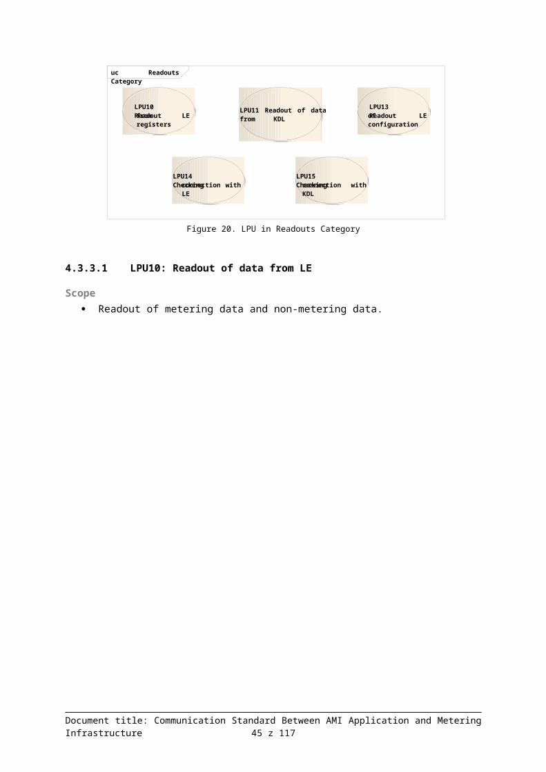
5 DCSML communication protocol The DCSML communication protocol was developed as an extension of the SML protocol (language) functionality. In order to ensure communication with data concentrators (KDL), a set of additional features was defined to ensure cooperation of SAK with KDL.
DCSML is used for communication between SAK and KDL. Also, it is a medium enabling transport of DLMS / COSEM protocol structures, which facilitates:
transmission of data read from COSEM objects in LE to SAK,
if necessary encapsulation of DLMS/COSEM commands at the SAK level, for KDL to transmit them directly to LE (DCMeterTransparent command).
5.1 Description of MessagesBased on the analysis of commands and data provided, a list of DCSML messages was developed which is presented in the table below.
Table 4. DCSML Message List
Message MeaningDCAttentionRequest Transmission of information, request, etc. Typical application includes a
request to read collected data in the "pull" mode. Also confirmation of information receipt.
DCAttentionResponse Notification of an alarm, confirmation of data receipt or execution of request, response to DCAttentionRequest.
DCFirmwareRequest Request to update software in KDL.DCGetParamRequest Request to read configuration and/or collected meter data from KDL.DCGetParamResponse Response with KDL configuration data.DCMeterAttentionResponse Acknowledgement of data receipt or request execution by individual LEs.DCMeterFirmwareRequest Request to update software in LE.DCMeterGetDataRequest Request to read data from LE.DCMeterGetDataResponse Response with data read from LE.DCMeterGetParamRequest Request to read configuration from LE.DCMeterGetParamResponse Response with LE configuration data.DCMeterSetParamRequest Request to change configuration of LE.DCMeterTransparentRequest Request to send data to LE in the APDU DLMS format.DCMeterTransparentResponse Response with LE data in the APDU DLMS format.DCSetParamRequest Request to change configuration of KDL.DCSubscribeRequest Request to create, change, delete or deactivate a subscription definition.
The message list is given in Appendix 2 in the "DCSML" worksheet. In the "LPU" worksheet, each individual LPU has been linked to DCSML messages that will be used to execute them.The "LPU <=> DCSML" worksheet presents the matrix of connections between LPU and DCSML messages.
5.2 Grammar of the Protocol
Document title: Communication Standard Between AMI Application and Metering Infrastructure 45 z 94

Due to the requirement for concentrators to be capable of working with meters from different manufacturers, it was assumed that the meters used will be compliant with the COSEM model. This means that logical devices, where COSEM objects are defined, are modeled in a physical device. Each object belongs to a certain interface class and is identified by OBIS code.
A DLMS / COSEM protocol is used to communicate with COSEM meters. It has been designed to record and transmit all data identified with OBIS codes, that is all data recorded in electricity meters.
For this reason, implementation of the DCSML protocol enables the following operations of the application layer:
Creating COSEM objects in LE based on interface classes defined in LE, removing those objects.
Performing the following types of operations on COSEM objects:o GET – get value of a COSEM object attribute, e.g. daily profile of values recorded
every 15 minutes, the actual voltage, etc.,o PUT – set the value of a COSEM object attribute, such as metering tariffs, calendar
used, etc.,o ACTION – run the method defined in a COSEM object.
Parameters and results of these operations are also encapsulated in DCSML messages to be passed between KDL and SAK.
5.2.1 Basic definitions of SML data structures
The concept of grammar for the DCSML protocol syntax is based on the solutions used in the SML protocol. DCSML is an extension of the SML protocol with additional functions. Functions of the SML protocol can be used equally with functions of the DCSML protocol. Therefore, in the description of grammar of the DCSML protocol we use the basic data structures (type) which are the same as in the original SML protocol. This applies to the following range of definitions of basic SML data structures:
OctetString Integer8 Integer16 Integer32 Integer64 Unsigned8 Unsigned16 Unsigned32 Unsigned64 Boolean List of … EndOfSmlMessage SML_Time SML_TimeStamp SML_Value SML_ValueEntry SML_Unit SML_Message SML_TreePath SML_Tree
Document title: Communication Standard Between AMI Application and Metering Infrastructure 46 z 94

List_of_SML_Tree List_of_SML_ObjReqEntry SML_ObjReqEntry List_of_SML_ProfObjHeaderEntry List_of_SML_ProfObjPeriodEntry List_of_SML_ValueEntry SML_ProfObjHeaderEntry SML_ProfObjPeriodEntry
Description of grammar of the DCSML protocol is presented in the same notation as was used in the description of SML (document: SML Smart Message Language Version1.03). The description uses the following characteristics defining the method of proceeding and interpreting the structures of elements in brackets:
CHOICE – means the possibility to choose one and only one element in brackets. The element must have its own unique code - TL field defining the type of the element (all the basic data types are assigned a unique TL code (TL-Field)
SEQUENCE – means that all the structure elements included in brackets are to be used, SEQUENCE OF – means an unlimited list of repetitive elements in brackets, OPTIONAL – means that the element specified by this characteristics does not have to be used
in the structure.
All the basic data types used in SML have a uniquely defined TL-Field. The size of a TL-Field is 1 byte (8 bits). Data type and data length expressed in terms of the number of bytes is encoded in this field. In TL-Field, the 4 most significant bits encode data type, while the 4 least significant bits encode information about the size of data in bytes. TL-Field is designed in such a way that, if the size of data described by TL-field is greater than 14 bytes then the most significant bit is set to 1 and it means that the next byte field after TL-Field carries additional information on data length. If additional bytes of TL-Field are used then the 4 bits of the first byte which specify data field length should be moved to the left by 4, while 4 bits from the next byte of the TL-Field should be added on the right. Thus, the maximum data field length of 254 may be encoded in 2 bytes of the TL-Field.
Encoding TL-Field (first byte)
Table 5. Significance of bits in the first byte of the TL-Field
Bit index MSBb7 6 5 4 3 2 1
LSBb0
The next byte is the extended TL-Field 1 X X X X X X X
The next byte is the value of data 0 X X X X X X X
Encoding Octet String data type X 0 0 0 L L L L
Encoding Boolean data type 0 1 0 0 L L L L
Encoding Integer data type X 1 0 1 L L L L
Encoding Unsigned data type X 1 1 0 L L L L
Encoding List of ... data type X 1 1 1 L L L L
The next byte allows you to define additional data types – reserved
1 1 0 0 L L L L
Document title: Communication Standard Between AMI Application and Metering Infrastructure 47 z 94

Bit index MSBb7 6 5 4 3 2 1
LSBb0
Reserved for the future X 0 0 1 L L L L
Reserved for the future X 0 1 0 L L L L
Reserved for the future X 0 1 1 L L L L
X - bit without significance (any bit value)L - data length bits (length in bytes)
TL-Field encoding (each subsequent byte)
Table 6. Significance of bits in subsequent bytes of the TL-Field
Bit index MSBb7 6 5 4 3 2 1
LSBb0
The next byte is the extended TL-Field 1 X X X X X X X
The next byte is the value of data 0 X X X X X X X
4 bits used as data length X 0 0 0 L L L L
Reserved for the future X 0 0 1 L L L L
Reserved for the future X 0 1 0 L L L L
Reserved for the future X 0 1 1 L L L L
Reserved for the future X 1 X X L L L L
5.2.1.1 OctetStringOctetString ::= SEQUENCE{
TL-Field 0x0z (‘z’ = number of bytes of data)
dataValue 0xAA..0xNN (0xAA – oldest byte,0xNN – youngest byte)
}
5.2.1.2 Integer8Integer8 ::= SEQUENCE{
TL-Field 0x52dataValue 0xYY
}
5.2.1.3 Integer16Integer16 ::= SEQUENCE{
TL-Field 0x53dataValue 0xAA 0xBB (0xAA – oldest byte,
0xBB – youngest byte,Size: Big Endian)
}
Document title: Communication Standard Between AMI Application and Metering Infrastructure 48 z 94

5.2.1.4 Integer32Integer32 ::= SEQUENCE{
TL-Field 0x55dataValue 0xAA 0xBB
0xCC 0xDD (0xAA – oldest byte,0xDD – youngest byte,Size: Big Endian)
}
5.2.1.5 Integer64Integer64 ::= SEQUENCE{
TL-Field 0x59dataValue 0xAA..0xHH 0xAA – oldest byte,
0xHH – youngest byte,Size: Big Endian)
}
5.2.1.6 Unsigned8Unsigned8 ::= SEQUENCE{
TL-Field 0x62dataValue 0xYY
}
5.2.1.7 Unsigned16Unsigned16 ::= SEQUENCE{
TL-Field 0x63dataValue 0xAA 0xBB (0xAA – oldest byte,
0xBB – youngest byte,Size: Big Endian)
}
5.2.1.8 Unsigned32Unsigned32 ::= SEQUENCE{
TL-Field 0x65dataValue 0xAA 0xBB
0xCC 0xDD (0xAA – oldest byte,0xDD – youngest byte,Size: Big Endian)
}
5.2.1.9 Unsigned64Unsigned64 ::= SEQUENCE{
TL-Field 0x59dataValue 0xAA..0xHH 0xAA – oldest byte,
0xHH – youngest byte,Size: Big Endian)
}
Document title: Communication Standard Between AMI Application and Metering Infrastructure 49 z 94

5.2.1.10 BooleanBoolean ::= SEQUENCE{
TL-Field 0x42dataValue 0xAA (0x00 = ‘false’
other value = ‘true’)}
5.2.1.11 List of …List of… ::= SEQUENCE{
TL-Field 0x7z (‘z’ = number of elements)}
5.2.1.12 EndOfSmlMessageEndOfSmlMessage ::= 0x00 (0x00 = no TL-Field
= end)
5.2.1.13 SML_TimeSML_Time ::= CHOICE{
secIndex 0x01 Unsigned32timestamp 0x02 SML_Timestamp
}
secIndex Time in seconds, counted number of seconds
timestamp SML_Timestamp (in seconds)
5.2.1.14 SML_TimeStampSML_TimeStamp time is based on a second. SML_TimeStamp counted from time 01.01.1970 00:00:00 (reference time of UNIX systems).
SML_TimeStamp ::= Unsigned32
5.2.1.15 SML_ValueSML_Value ::= IMPLICIT CHOICE{
Boolean-Value BooleanByte-List OctetString8-Bit-Integer Integer816-Bit-Integer Integer1632-Bit-Integer Integer3264-Bit-Integer Integer648-Bit-Unsigned Unsigned816-Bit-Unsigned Unsigned1632-Bit-Unsigned Unsigned3264-Bit-Unsigned Unsigned64
}
5.2.1.16 SML_ValueEntrySML_ValueEntry ::= SEQUENCE
Document title: Communication Standard Between AMI Application and Metering Infrastructure 50 z 94

{value SML_ValuevalueSignature SML_Signature OPTIONAL
}
5.2.1.17 SML_SignatureSignature is used to set the profile signature, parameter or values. Signatures vary for different individual system implementations.
SML_Signature OctetString
5.2.1.18 SML_UnitThe table of numerical values assigned to respective physical units is provided in the documents describing the DLMS (PN-EN 62056-62).
SML_Unit ::= Unsigned8
5.2.1.19 SML_Message
The basic structure of a SML message is used to send queries and responses in the communication process using the SML protocol.
SML_Message ::= SEQUENCE{
transactionID OctetStringgroupID Unsigned8abortOnError Unsigned8messageBody SML_MessageBodycrc16 Unsigned16endOfSmlMsg EndOfSmlMsg
}
5.2.1.20 SML_TreePathSML_TreePath ::= SEQUENCE OF{
Path_Entry OctetString}
5.2.1.21 SML_TreeSML_Tree allows you to obtain various information about parameters. Because of the tree structure and the child_list field, we can get information about:
a single parameter, a parameter with a list of dependent parameters, a parameter with a list of dependent parameter trees,
Parameter name is an appropriate OBIS code.
SML_Tree ::= SEQUENCE{
parameterName OctetStringparameterValue SML_ProcParValue OPTIONALchild_list List_of_SML_Tree OPTIONAL
Document title: Communication Standard Between AMI Application and Metering Infrastructure 51 z 94

}
5.2.1.22 List_of_SML_TreeList_of_SML_Tree ::= SEQUENCE OF{
tree_Entry SML_Tree}
5.2.1.23 List_of_SML_ObjReqEntryList_of_SML_ObjReqEntry ::= SEQUENCE OF{
object_List_Entry SML_ObjReqEntry}
5.2.1.24 SML_ObjReqEntryName of the parameter whose value is to be read (OBIS code).
SML_ObjReqEntry ::= OctetString
5.2.1.25 List_of_SML_ProfObjHeaderEntryList_of_SML_ProfObjHeaderEntry ::= SEQUENCE OF{
Header_List_Entry SML_ProfObjHeaderEntry}
5.2.1.26 List_of_SML_ProfObjPeriodEntryList_of_SML_ProfObjPeriodEntry ::= SEQUENCE OF{
Period_List_Entry SML_ProfObjPeriodEntry}
5.2.1.27 List_of_SML_ValueEntryList_of_SML_ValueEntry ::= SEQUENCE OF{
Value_List_Entry SML_ValueEntry}
5.2.1.28 SML_ProfObjHeaderEntryThe structure describes properties of a single parameter whose value or valueset we read. Information included in SML_ProfObjHeaderEntry are static for a specified parameter named objname.
SML_ProfObjHeaderEntry ::= SEQUENCE{
objName OctetStringunit SML_Unitscaler Integer8
}
5.2.1.29 SML_ProfObjPeriodEntryThe structure is used to return a set of values of parameters specified in the list List_of_SML_ProfObjHeaderEntry in association with a specified value of LE time when the data was measured. Data consistency signature may be assigned to a set of LE data from a specified time.
SML_ProfObjPeriodEntry ::= SEQUENCE
Document title: Communication Standard Between AMI Application and Metering Infrastructure 52 z 94
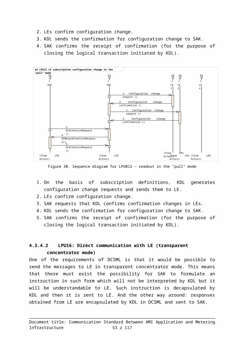
{valTime SML_Timestatus Unsigned64value_List List_of_SML_ValueEntryperiodSignature SML_Signature OPTIONAL
}
5.2.1.30 SML_MessageBody
Definition of the SML_MessageBody syntax has been extended to include additional message structure types. The definition of SML_MessageBody retains the previous types of structures defined in SML (IDs from 0x00000100 to 0x0000FF01).
SML_MessageBody ::= CHOICE{
OpenRequest [0x00000100] SML_PublicOpen.ReqOpenResponse [0x00000101] SML_PublicOpen.ResCloseRequest [0x00000200] SML_PublicClose.ReqCloseResponse [0x00000201] SML_PublicClose.ResGetProfilePackRequest [0x00000300] SML_GetProfilePack.ReqGetProfilePackResponse [0x00000301] SML_GetProfilePack.ResGetProfileListRequest [0x00000400] SML_GetProfileList.ReqGetProfileListResponse [0x00000401] SML_GetProfileList.ResGetProcParameterRequest [0x00000500] SML_GetProcParameter.ReqGetProcParameterResponse [0x00000501] SML_GetProcParameter.ResSetProcParameterRequest [0x00000600] SML_SetProcParameter.ReqSetProcParameterResponse [0x00000601] SML_SetProcParameter.ResAttentionResponse [0x0000FF01] SML_Attention.ResDCFirmwareRequest [0x10000300] DCFirmware.ReqDCGetParamRequest [0x10000400] DCGetParam.ReqDCGetParamResponse [0x10000401] DCGetParam.ResDCSetParamRequest [0x10000500] DCSetParam.ReqDCSubscribeRequest [0x10000600] DCSubscribe.ReqDCAttentionRequest [0x10000700] DCAttention.ReqDCAttentionResponse [0x10000701] DCAttention.ResDCMeterGetDataRequest [0x10000800] DCMeterGetData.ReqDCMeterGetDataResponse [0x10000801] DCMeterGetData.ResDCMeterGetParamRequest [0x10000900] DCMeterGetParam.ReqDCMeterGetParamResponse [0x10000901] DCMeterGetParam.ResDCMeterSetParamRequest [0x10001000] DCMeterSetParam.ReqDCMeterTransparentRequest [0x10001100] DCMeterTransparent.ReqDCMeterTransparentResponse[0x10001101] DCMeterTransparent.ResDCMeterFirmwareRequest [0x10001200] DCMeterFirmware.ReqDCMeterAttentionResponse [0x10001301] DCMeterAttention.Res
}
5.2.2 Basic structures of DCSML dataThe basic structure of DCSML data with fundamental grammar structures of the SML protocol form the basis describing all the grammatical structures of DCSML queries and responses.
5.2.2.1 List_of_DCSML_ServerID
Structure of the data server ID list (LE).
List_of_DCSML_ServerID ::= SEQUENCE OF
Document title: Communication Standard Between AMI Application and Metering Infrastructure 53 z 94

{serverID OctetString
{
serverID Data server ID (LE).
5.2.2.2 DCSML_ServerIDData
Set of data returned for a particular LE
DCSML_ServerIDData ::= SEQUENCE{
serverID OctetStringheader_List List_of_SML_ProfObjHeaderEntryperiod_List List_of_SML_ProfObjPeriodEntry
}
serverID Data server ID (LE).
header_List List of headers describing a parameter (standard SML structure)
period_List List of parameter values (standard SML structure)
5.2.2.3 List_of_DCSML_ServerIDData
List of structures DCSML_ServerIDData.
List_of_DCSML_ServerIDData ::= SEQUENCE OF{
serverIDAnswers DCSML_ServerIDData}
5.2.2.4 DCSML_ServerIDParams
Set of information required to record specific parameters from a specified meter.
DCSML_ServerIDParams ::= SEQUENCE{
serverID OctetStringparameterTree SML_Tree
}
serverID Data server ID (LE).
parameterTree Tree of LE parameters with their values
5.2.2.5 List_of_DCSML_ServerIDParamsList of structures DCSML_ServerIDParams.
List_of_DCSML_ServerIDParams ::= SEQUENCE OF{
serverParams DCSML_ServerIDParams}
5.2.2.6 DCSML_MeterAttention
Document title: Communication Standard Between AMI Application and Metering Infrastructure 54 z 94

Attention message from a single LE.
DCSML_MeterAttention ::= SEQUENCE{
serverID OctetStringattentionNo OctetStringattentionDetails SML_Tree OPTIONAL
}
serverID Data server ID (LE).
attentionNo Code of message transmitted by that message.
attentionDetails Structure enabling the transfer of additional attributes that are required in a given case.
5.2.2.7 List_of_DCSML_MeterAttention
List of messages DCSML_MeterAttention for a specified group of (multiple) LEs.
List_of_DCSML_MeterAttention ::= SEQUENCE OF{
meterStatus DCSML_MeterAttention}
5.2.2.8 DCSML_CycleTimeDCSML_ReadCycleTime ::= CHOICE{
cycle 0x01 SML Timedayofmonth 0x02 Unsigned8
}
5.2.2.9 DCSML_IndexTimeDCSML_IndexTime ::= CHOICE{
time 0x01 SML Timeindex 0x02 Unsigned16
}
5.2.3 DCSML Functions – associated with the operation of a concentrator
5.2.3.1 DCFirmwareDCFirmware.Req ::= SEQUENCE{
priority Unsigned8startTime SML_TimerawData Octet String
}
Document title: Communication Standard Between AMI Application and Metering Infrastructure 55 z 94

priority Task priority.
startTime Date when KDL is to reload the firmware.
rawData Raw data – package of data containing firmware for KDL.
5.2.3.2 DCGetParamDCGetParam.Req ::= SEQUENCE{
priority Unsigned8parameterTreePath SML_TreePath
}DCGetParam.Res ::= SEQUENCE{
parameterTreePath SML_TreePathparameterTree SML_Tree
}
priority Task priority.
parameterTreePath KDL parameter tree.
parameterTree Parameter tree with parameter values.
5.2.3.3 DCSetParamDCSetParam.Req ::= SEQUENCE{
priority Unsigned8function Unsigned8startTime SML_Time OPTIONALparameterTreePath SML_TreePathparameterTree SML_Tree
}
priority Task priority.
function Code specifying the actions to be performed: e.g. creation and configuration of a new object, modification of parameter values, object removal (bit encoding, which means that it is several commands can be made with a single command).
startTime Date indicating the time when KDL should change the settings.
parameterTreePath IDs of KDL parameters to be set.
parameterTree Values of KDL parameters to be set.
5.2.3.4 DCSubscribeDCSubscribe.Req ::= SEQUENCE{
priority Unsigned8
Document title: Communication Standard Between AMI Application and Metering Infrastructure 56 z 94

listserverID List_of_DCSML_ServerIDsubscribeID Octet Stringfunction Unsigned8beginTime SML_Time OPTIONALendTime SML_Time OPTIONALreadCycleTime DCSML_CycleTimesendCycleTime DCSML_CycleTime OPTIONALdataTreePath SML_TreePath OPTIONALdataTree SML_Tree OPTIONAL
}
priority Task priority
listserverID List of data servers (LE), for which subscription is to be created, changed, deactivated or removed.
subscribeID Subscription ID.
Function Code indicating the actions to be performed on the definition of the subscription.
beginTime Beginning time of the subscription period (commencement of subscription); if the parameter is not stated then the concentrator then the concentrator should begin subscription when the order is received.
endTime End time of the subscription period (end of subscription); if the parameter is not stated then the concentrator then the concentrator should continue subscription until it is canceled or deactivated.
readCycleTime Parameter to be entered: subscription cycle (time interval in minutes or a specific day of the month).
SendCycleTime Parameter to be entered: collected data sending cycle (time interval in minutes or a specific day of the month). If the parameter is not stated then data will be sent immediately after they are collected.
dataTreePath IDs of configured LE parameters or subscribed data.
dataTree Values of LE parameters to be set in subscription.
5.2.3.5 DCAttentionDCAttention.Req ::= SEQUENCE{
priority Unsigned8attentionNo OctetStringattentionDetails SML_Tree OPTIONAL
}
DCAttention.Res ::= SEQUENCE{
priority Unsigned8attentionNo OctetStringattentionDetails SML_Tree OPTIONAL
}
Document title: Communication Standard Between AMI Application and Metering Infrastructure 57 z 94

priority Task priority.
attentionNo Code of message transmitted by that DCAttention message.
attentionDetails Structure enabling the transfer of additional attributes that are required in a given case.
5.2.4 DCSML functions – associated with the operation of a meter
5.2.4.1 DCMeterGetDataDCMeterGetData.Req ::= SEQUENCE{
priority Unsigned8subscribeID Octet String OPTIONALlistserverID List_of_DCSML_ServerIDbeginindextime DCSML_IndexTimeendindextime DCSML_IndexTimeparameterTreePath SML_TreePath OPTIONAL
}DCMeterGetData.Res ::= SEQUENCE{
subscribeID Octet String OPTIONALparameterTreePath SML_TreePathlistserverIDData List_of_DCSML_ServerIDData
}
priority Task priority.
subscribeID Subscription iD (optional parameter).
listserverID List of data servers (LE).
beginindextime Beginning time of the queried period or initial data index.
endindextime End time of the queried period or final data index.
parameterTreePath LE parameter tree.
listserverIDData List of responses with data from servers (LE).
5.2.4.2 DCMeterGetParamDCMeterGetParam.Req ::= SEQUENCE{
priority Unsigned8listserverID List_of_DCSML_ServerIDparameterTreePath SML_TreePath
}DCMeterGetParam.Res ::= SEQUENCE{
parameterTreePath SML_TreePathlistserverIDParams List_of_DCSML_ServerIDParams
}
listserverID List of data servers (LE).
Document title: Communication Standard Between AMI Application and Metering Infrastructure 58 z 94

parameterTreePath LE parameter tree.
listserverIDParams List of responses with parameters from servers (LE).
5.2.4.3 DCMeterSetParamDCMeterSetParam.Req ::= SEQUENCE{
priority Unsigned8function Unsigned8startTime SML_Time OPTIONALparameterTreePath SML_TreePathlistserverParams List_of_DCSML_ServerIDParams
}
priority Task priority.
function Code specifying the actions to be performed: e.g. creation and configuration of a new COSEM object, modification of parameter values, COSEM object removal; action call (bit encoding, which means that it is several commands can be made with a single command).
startTime Date when LEs are to change the settings. If the parameter is not set parameter switching occurs immediately.
parameterTreePath LE parameter tree.
listserverParams List of LEs with the list of parameters read from LE.
5.2.4.4 DCMeterTransparentDCMeterTransparent.Req ::= SEQUENCE{
priority Unsigned8serverID Octet StringrawData Octet String
}DCMeterTransparent.Res ::= SEQUENCE{
serverID Octet StringrawData Octet String
}
priority Task priority.
serverID Data server ID (LE).
rawData Raw data – package of data to be sent to LE (or a response from LE) in the APDU DLMS format.
5.2.4.5 DCMeterFirmwareDCMeterFirmware.Req ::= SEQUENCE
Document title: Communication Standard Between AMI Application and Metering Infrastructure 59 z 94

{priority Unsigned8listserverID List_of_DCSML_ServerIDstartTime SML_TimerawData Octet String
}
priority Task priority.
listserverID List of data servers (LE).
startTime Date specifying when LE is to reload the firmware.
rawData Raw data – package of data containing firmware for LE.
meterList List of the structure describing the LE firmware replacement status.
5.2.4.6 DCMeterAttentionResponseDCMeterAttention.Res ::= SEQUENCE{
attentionID List_of_DCSML_MeterAttention}
attentionID List of messages from multiple LE meters
Document title: Communication Standard Between AMI Application and Metering Infrastructure 60 z 94

6 Examples of queries and responses in DCSML (in APDU and source forms)
This chapter presents sample test data used in the tests and the resulting APDU. All the examples pertain to the DCSML language.
The APDU examples presented in this appendix were generated using a tool written in Java. The tool works in such a way that, based on a definition in ASN.1, objects for individual APDUs are created in the application and populated with data. Then a file with APDU is generated. The tool based on a generally available freeware library is described in document P.1.4., item 7.4.
The APDUs presented below were generated for 1 and 5 meters in the following situations (x meaning the number of meters):
1. Query for a single value and its reading (hereinafter denoted as x-1-1).2. Query for a profile with a single value (a column) and a reading of a 15-minute hourly profile
(4 readings recorded every 15 minutes) (hereinafter denoted as x-1-4).3. Query for 5 values and their reading (hereinafter denoted as x-5-1).4. Query for a profile with a 5 values (columns) and a reading of a 15-minute hourly profile (4
readings recorded every 15 minutes) (hereinafter denoted as x-5-4).
The document contains the following examples:
1. Contents of the ASN.1 definition file which was used to generate the examples included in this document.
2. Documentation of the cases listed above for 1 and 5 meters.a. APDU queries in a hexadecimal form and, for easier analysis, in a parenthesis form.b. APDU responses in a hexadecimal and parenthesis form.c. For easier analysis in the parenthesis form, the numbers (time and data) were recoded
to a hexadecimal form.
It should be noted that the tools used offer encoding to a standard BER format. The SML standard used slightly optimized BER encoding – where possible, Type and Length are encoded in a single byte. This offers potentially additional possibilities to reduce the size of the APDU file.
6.1 ASN.1 definitionBelow you will find the definition of grammar used to generate the examples provided underneath. The definition is given in the ASN.1 notation
DCSMLTest DEFINITIONS AUTOMATIC TAGS ::= BEGIN
INTEGER8 ::= INTEGER (-128..127)UNSIGNED8 ::= INTEGER (0..255)UNSIGNED16 ::= INTEGER (0..65535)UNSIGNED32 ::= INTEGER (0..4294967295)UNSIGNED64 ::= UNSIGNED32
SMLPublicOpen-Req ::= SEQUENCE{
clientId OCTET STRING,
Document title: Communication Standard Between AMI Application and Metering Infrastructure 61 z 94

serverId OCTET STRING OPTIONAL}
SMLPublicOpen-Res ::= SEQUENCE{
clientId OCTET STRING,serverId OCTET STRING OPTIONAL
}
DCMeterGetData-Req ::= SEQUENCE{
listserverID List-of-DCSML-ServerID,subscribeID OCTET STRING OPTIONAL,questionID UNSIGNED32,answerID UNSIGNED16,beginTime UNSIGNED32 OPTIONAL,endTime UNSIGNED32 OPTIONAL,parameterTreePath SMLTreePath
}
DCMeterGetData-Res ::= SEQUENCE{
subscribeID OCTET STRING OPTIONAL,questionID UNSIGNED32,answerID UNSIGNED16,parameterTreePath SMLTreePath,listserverIDAnswers List-of-DCSML-ServerIDAnswers
}
SMLPublicClose-Req ::= SEQUENCE{
globalSignature SMLSignature OPTIONAL}
SMLPublicClose-Res ::= SEQUENCE{
globalSignature SMLSignature OPTIONAL}
SMLTreePath ::= SEQUENCE OF OCTET STRING
ListOfSMLHeader ::= SEQUENCE OF SMLHeaderEntry
ListOfSMLPeriod ::= SEQUENCE OF SMLProfObjPeriodEntry
SMLProfObjPeriodEntry ::= SEQUENCE
{valTime UNSIGNED32,status UNSIGNED64,valueList ListOfSMLValueEntry
}
ListOfSMLValueEntry ::= SEQUENCE OF UNSIGNED16
SMLHeaderEntry ::= SEQUENCE{
objName OCTET STRING,unit INTEGER8,scaler INTEGER8
}
SMLSignature ::= OCTET STRING
List-of-DCSML-ServerID ::= SEQUENCE OF OCTET STRING
List-of-DCSML-ServerIDAnswers ::= SEQUENCE OF DCSML-ServerIDAnswers
Document title: Communication Standard Between AMI Application and Metering Infrastructure 62 z 94

DCSML-ServerIDAnswers ::= SEQUENCE{
serverID OCTET STRING,header-List SEQUENCE OF SMLHeaderEntry,period-List SEQUENCE OF SMLProfObjPeriodEntry
}Figure 36: Definition of grammar in ASN.1 notation
6.2 Examples
6.2.1 Example 1-1-1
6.2.1.1 Queryoffset 0 1 2 3 4 5 6 7 8 9 10 11 12 13 14 15 ascii
00000000 30 24 80 10 43 4C 49 45 4E 54 2D 5A 33 44 57 59 0$€.CLIENT-Z3DWY00000010 34 34 35 35 81 10 53 45 52 56 45 52 2D 5A 55 31 4455 �.SERVER-ZU100000020 54 4B 44 54 57 42 30 33 A0 12 04 10 53 45 52 56 TKDTWB03 ...SERV00000030 45 52 2D 52 56 4C 47 35 39 55 31 34 82 04 0F 89 ER-RVLG59U14‚..‰00000040 35 E6 83 02 55 31 84 04 4D F0 9F FF 85 04 4D F0 5ć�.U1„.Mđź˙….Mđ00000050 A3 83 A6 07 04 05 31 2E 38 2E 30 30 00 00 00 00 Ł¦� ...1.8.00....
Figure 37: Response 1-1-4 in the APDU form
The figure above shows the contents of the generated APDU in a hexadecimal and a character form. BER encoding has been applied, more precisely: encoding implemented in a generally available "ASN.1 to Java Compiler" tool by ASNLab.
A description of the contents of that APDU follows; accuracy according to data that could be identified:
30 SEQUENCE SMLPublicOpen-Req24 number of bytes in SEQUENCE (36)80 unidentified10 number of bytes in clientId (16)43 to 35 clientId (CLIENT-Z3DWY4455)81 unidentified10 number of bytes in serverId (16) (SERVER-ZU1TKDTWB03)30 SEQUENCE DCMeterGetData-Req33 number of bytes in SEQUENCE (51)A0 SEQUENCE OF listserverID12 number of bytes in SEQUENCE OF (18)04 unidentified10 number of bytes of the first (and in this case the last)
element of listserverID (16)53 to 34 first element of listserverID (SERVER-RVLG59U14)82 unidentified04 number of bytes in questionID (4)0F to E6 questionID (260650470)83 unidentified02 number of bytes in answerID (2)55 31 answerID (21809)84 unidentified04 number of bytes in beginTime (4)4D to FF beginTime (1307615231)85 unidentified04 number of bytes in endTime (4)4D to 83 endTime (1307616131)A6 SEQUENCE OF parameterTreePath
Document title: Communication Standard Between AMI Application and Metering Infrastructure 63 z 94

07 number of bytes in SEQUENCE OF (7)04 unidentified05 number of bytes of the first (and in this case the last)
element of parameterTreePath (5)31 to 30 OBIS code (1.8.0)30 SEQUENCE SMLPublicClose-Req00 number of bytes in SEQUENCE (0)00 end of data00 00 00 supplementation to the multiple of 4 bytes
It should be stressed again that in the case of DCSML a slightly more efficient APDU encoding will be used, applied to APDU in the SML language.
SMLPublicOpen_Req {CLIENT-Z3DWY4455,SERVER-ZU1TKDTWB,
}DCMeterGetData_Req {
listserverID {SERVER-RVLG59U14,
}260650470 [HEX: 0F 89 35 E6],21809 [HEX: 55 31],1307615231 [HEX: 4D F0 9F FF] (Thu Jun 09 12:27:11 CEST 2011),1307616131 [HEX: 4D F0 A3 83] (Thu Jun 09 12:42:11 CEST 2011),parameterTreePath {
1.8.0,}
}SMLPublicClose_Req {}
Figure 38: Query 1-1-1 in ASN.1 notation
6.2.1.2 Responseoffset 0 1 2 3 4 5 6 7 8 9 10 11 12 13 14 15 ascii
00000000 30 24 80 10 43 4C 49 45 4E 54 2D 5A 33 44 57 59 0$€.CLIENT-Z3DWY00000010 34 34 35 35 81 10 53 45 52 56 45 52 2D 5A 55 31 4455 �.SERVER-ZU100000020 54 4B 44 54 57 42 30 4D 81 04 50 29 4B 35 82 02 TKDTWB0M �.P)K5‚.00000030 4E 97 A3 07 04 05 31 2E 38 2E 30 A4 38 30 36 80 N—Ł...1.8.0¤806€00000040 10 53 45 52 56 45 52 2D 52 56 4C 47 35 39 55 31 .SERVER-RVLG59U100000050 34 A1 0F 30 0D 80 05 31 2E 38 2E 30 81 01 05 82 4ˇ.0.€.1.8.0 �..‚00000060 01 01 A2 11 30 0F 80 04 4D F0 9F FF 81 01 08 A2 ..˘.0.€.Mđź˙ �..˘00000070 04 02 02 6B 0B 30 00 00 00 00 00 00 00 00 00 00 ...k.0..........
Figure 39: Response 1-1-1 in the APDU form
SMLPublicOpen_Res {CLIENT-Z3DWY4455,SERVER-ZU1TKDTWB,
}DCMeterGetData_Res {
1344883509 [HEX: 50 29 4B 35],20119 [HEX: 4E 97],parameterTreePath {
1.8.0,
Document title: Communication Standard Between AMI Application and Metering Infrastructure 64 z 94
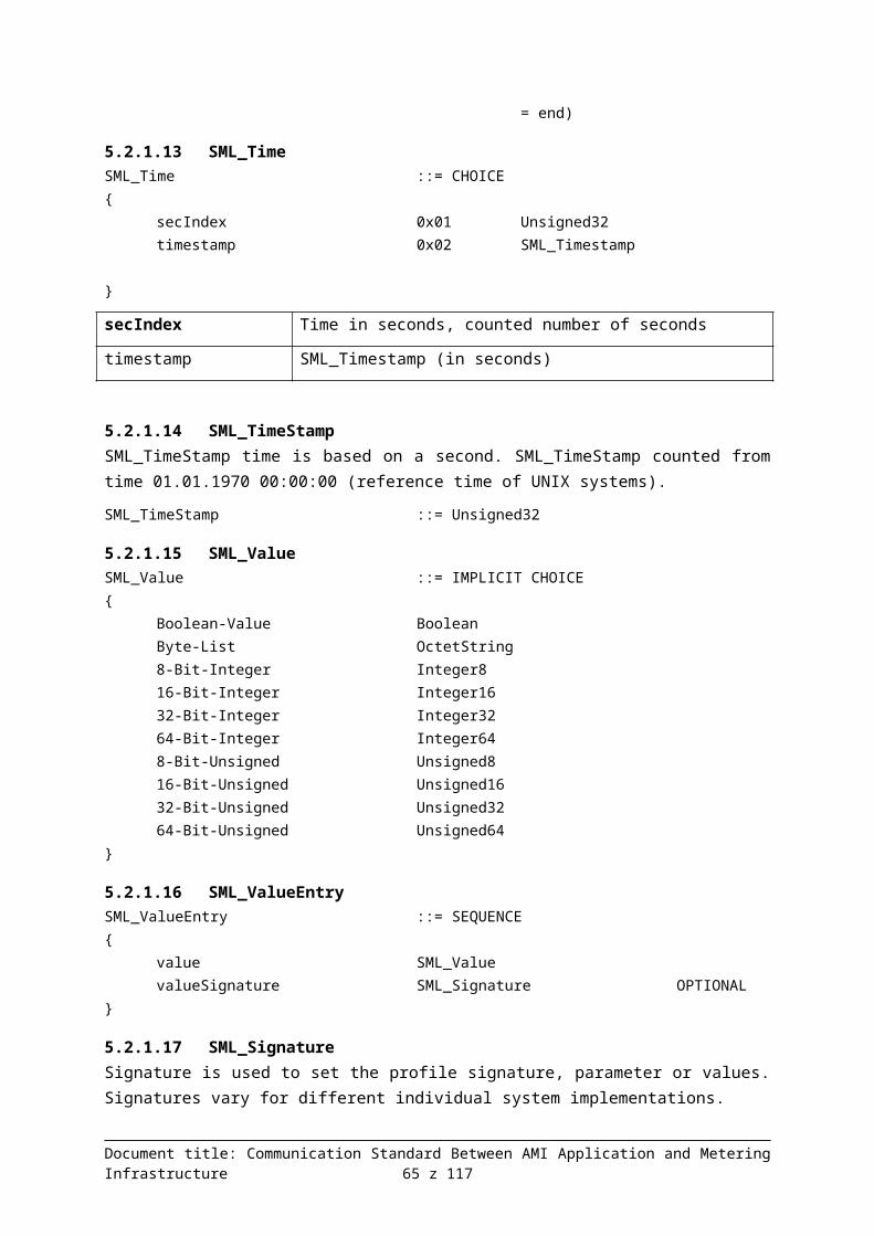
}DCSML_ServerIDAnswers {
SERVER-RVLG59U14,{
SMLHeaderEntry { 1.8.0, 5, 1 }}{
SMLProfObjPeriodEntry {1307615231 [HEX: 4D F0 9F FF] (Thu Jun 09 12:27:11 CEST
2011),8,{
27403 [HEX: 6B 0B],}
}}
}}SMLPublicClose_Res {}
Figure 40: Response 1-1-1 in ASN.1 notation
6.2.2 Example 1-1-4
6.2.2.1 Queryoffset 0 1 2 3 4 5 6 7 8 9 10 11 12 13 14 15 ascii
00000000 30 24 80 10 43 4C 49 45 4E 54 2D 38 5A 4A 31 34 0$€.CLIENT-8ZJ1400000010 49 45 56 42 81 10 53 45 52 56 45 52 2D 43 4F 47 IEVB �.SERVER-COG00000020 39 34 49 32 36 45 30 33 A0 12 04 10 53 45 52 56 94I26E03 ...SERV00000030 45 52 2D 55 4D 36 30 4A 4D 59 44 34 82 04 5B 25 ER-UM60JMYD4‚.[%00000040 A6 88 83 02 17 C3 84 04 4D F0 A5 CF 85 04 4D F0 ¦��..Ă„.MđĄĎ….Mđ00000050 B3 DF A6 07 04 05 31 2E 38 2E 30 30 00 00 00 00 łß¦...1.8.00....
Figure 41: Response 1-1-4 in the APDU form
SMLPublicOpen_Req {CLIENT-8ZJ14IEVB,SERVER-COG94I26E,
}DCMeterGetData_Req {
listserverID {SERVER-UM60JMYD4,
}1529194120 [HEX: 5B 25 A6 88],6083 [HEX: 17 C3],1307616719 [HEX: 4D F0 A5 CF] (Thu Jun 09 12:51:59 CEST 2011),1307620319 [HEX: 4D F0 B3 DF] (Thu Jun 09 13:51:59 CEST 2011),parameterTreePath {
1.8.0,}
}SMLPublicClose_Req {}
Figure 42: Query 1-1-4 in ASN.1 notation
6.2.2.2 Response
Document title: Communication Standard Between AMI Application and Metering Infrastructure 65 z 94

offset 0 1 2 3 4 5 6 7 8 910
11
12
13 14
15 ascii
00000000
30
24
80
10
43
4C
49
45
4E
54
2D
38
5A
4A 31
34
0$€.CLIENT-8ZJ14
00000010
49
45
56
42
81
10
53
45
52
56
45
52
2D
43 4F
47 IEVB�.SERVER-COG
00000020
39
34
49
32
36
45
30
81
82
81
04
49
48
55 C4
82 94I26E0‚� �.IHUÄ‚
00000030
02
65
9A
A3
07
04
05
31
2E
38
2E
30
A4
6D 30
6B
.ešŁ...1.8.0¤m0k
00000040
80
10
53
45
52
56
45
52
2D
55
4D
36
30
4A 4D
59
€.SERVER-UM60JMY
00000050
44
34
A1
0F
30
0D
80
05
31
2E
38
2E
30
81 01
05 D4ˇ.0.€.1.8.0 �..
00000060
82
01
01
A2
46
30
10
80
04
4D
F0
A5
CF
81 01
08 ‚..˘F0.€.MđĄĎ �..
00000070
A2
05
02
03
00
D6
28
30
0F
80
04
4D
F0
A9 53
81 ˘....Ö(0.€.Mđ©S �
00000080
01
08
A2
04
02
02
2B
CA
30
10
80
04
4D
F0
MOD
D7
..˘...+Ę0.€.Mđ¬×
00000090
81
01
08
A2
05
02
03
00
9D
8F
30
0F
80
04 4D
F0 �..˘....ťŹ0.€.Mđ
000000A0
B0
5B
81
01
08
A2
04
02
02
59
8B
30
00
00 00
00 °[�..˘...Y‹0....
Figure 43: Response 1-1-4 in the APDU form
SMLPublicOpen_Res {CLIENT-8ZJ14IEVB,SERVER-COG94I26E,
}DCMeterGetData_Res {
1229477316 [HEX: 49 48 55 C4],26010 [HEX: 65 9A],parameterTreePath {
1.8.0,}DCSML_ServerIDAnswers {
SERVER-UM60JMYD4,{
SMLHeaderEntry { 1.8.0, 5, 1 }}{
SMLProfObjPeriodEntry {1307616719 [HEX: 4D F0 A5 CF] (Thu Jun 09 12:51:59 CEST
2011),8,{
54824 [HEX: D6 28],}
}SMLProfObjPeriodEntry {
1307617619 [HEX: 4D F0 A9 53] (Thu Jun 09 1:06:59 PM CEST 2011),
8,{
11210 [HEX: 2B CA],}
}SMLProfObjPeriodEntry {
1307618519 [HEX: 4D F0 AC D7] (Thu Jun 09 13:21:59 CEST
Document title: Communication Standard Between AMI Application and Metering Infrastructure 66 z 94

2011),8,{
40335 [HEX: 9D 8F],}
}SMLProfObjPeriodEntry {
1307619419 [HEX: 4D F0 B0 5B] (Thu Jun 09 1:36:59 PM CEST 2011),
8,{
22923 [HEX: 59 8B],}
}}
}}SMLPublicClose_Res {}
Figure 44: Response 1-1-4 in ASN.1 notation
6.2.3 Example 1-5-1
6.2.3.1 Queryoffset 0 1 2 3 4 5 6 7 8 9 10 11 12 13 14 15 ascii
00000000 30 24 80 10 43 4C 49 45 4E 54 2D 45 4B 4C 44 46 0$€.CLIENT-EKLDF00000010 4E 33 5A 50 81 10 53 45 52 56 45 52 2D 4F 4B 53 N3ZP �.SERVER-OKS00000020 4C 44 53 54 48 54 30 50 A0 12 04 10 53 45 52 56 LDSTHT0P ...SERV00000030 45 52 2D 47 54 45 35 31 4C 34 42 32 82 04 5D 0B ER-GTE51L4B2‚.].00000040 57 5C 83 03 00 9A F6 84 04 4D F0 A5 CF 85 04 4D W\�..šö„.MđĄĎ….M00000050 F0 A9 53 A6 23 04 05 31 2E 38 2E 30 04 05 32 2E đ©S¦#..1.8.0..2.00000060 38 2E 30 04 05 35 2E 38 2E 30 04 05 36 2E 38 2E 8.0..5.8.0..6.8.00000070 30 04 05 37 2E 38 2E 30 30 00 00 00 00 00 00 00 0..7.8.00.......
Figure 45: Response 1-5-4 in the APDU form
SMLPublicOpen_Req {CLIENT-EKLDFN3ZP,SERVER-OKSLDSTHT,
}DCMeterGetData_Req {
listserverID {SERVER-GTE51L4B2,
}1561024348 [HEX: 5D 0B 57 5C],39670 [HEX: 9A F6],1307616719 [HEX: 4D F0 A5 CF] (Thu Jun 09 12:51:59 CEST 2011),1307617619 [HEX: 4D F0 A9 53] (Thu Jun 09 1:06:59 PM CEST 2011),parameterTreePath {
1.8.0,2.8.0,5.8.0,6.8.0,7.8.0,
}
Document title: Communication Standard Between AMI Application and Metering Infrastructure 67 z 94
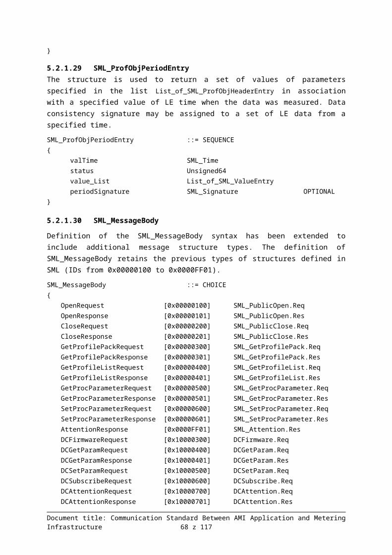
}SMLPublicClose_Req {}
Figure 46: Query 1-5-1 in ASN.1 notation
6.2.3.2 Response00000000 30 24 80 10 43 4C 49 45 4E 54 2D 45 4B 4C 44 46 0$€.CLIENT-EKLDF00000010 4E 33 5A 50 81 10 53 45 52 56 45 52 2D 4F 4B 53 N3ZP �.SERVER-OKS00000020 4C 44 53 54 48 54 30 81 BA 81 04 7C ED 10 F9 82 LDSTHT0ş� �.|í.ů‚00000030 03 00 98 63 A3 23 04 05 31 2E 38 2E 30 04 05 32 ..�cŁ#..1.8.0..200000040 2E 38 2E 30 04 05 35 2E 38 2E 30 04 05 36 2E 38 .8.0..5.8.0..6.800000050 2E 30 04 05 37 2E 38 2E 30 A4 81 87 30 81 84 80 .0..7.8.0¤‡� 0„€�00000060 10 53 45 52 56 45 52 2D 47 54 45 35 31 4C 34 42 .SERVER-GTE51L4B00000070 32 A1 4B 30 0D 80 05 31 2E 38 2E 30 81 01 05 82 2ˇK0.€.1.8.0 �..‚00000080 01 01 30 0D 80 05 32 2E 38 2E 30 81 01 07 82 01 ..0.€.2.8.0 �..‚.00000090 01 30 0D 80 05 35 2E 38 2E 30 81 01 08 82 01 01 .0.€.5.8.0 �..‚..000000A0 30 0D 80 05 36 2E 38 2E 30 81 01 04 82 01 01 30 0.€.6.8.0 �..‚..0000000B0 0D 80 05 37 2E 38 2E 30 81 01 01 82 01 01 A2 23 .€.7.8.0 �..‚..˘#000000C0 30 21 80 04 4D F0 A5 CF 81 01 08 A2 16 02 02 55 0!€.MđĄĎ �..˘...U000000D0 46 02 02 50 D1 02 03 00 BE F1 02 02 0A 2F 02 03 F..PŃ...ľń.../..000000E0 00 D9 D2 30 00 00 00 00 00 00 00 00 00 00 00 00 .ŮŇ0............
Figure 47: Response 1-5-1 in the APDU form
SMLPublicOpen_Res {CLIENT-EKLDFN3ZP,SERVER-OKSLDSTHT,
}DCMeterGetData_Res {
2095911161 [HEX: 7C ED 10 F9],39011 [HEX: 98 63],parameterTreePath {
1.8.0,2.8.0,5.8.0,6.8.0,7.8.0,
}DCSML_ServerIDAnswers {
SERVER-GTE51L4B2,{
SMLHeaderEntry { 1.8.0, 5, 1 }SMLHeaderEntry { 2.8.0, 7, 1 }SMLHeaderEntry { 5.8.0, 8, 1 }SMLHeaderEntry { 6.8.0, 4, 1 }SMLHeaderEntry { 7.8.0, 1, 1 }
}{
SMLProfObjPeriodEntry {1307616719 [HEX: 4D F0 A5 CF] (Thu Jun 09 12:51:59 CEST
2011),8,{
21830 [HEX: 55 46],
Document title: Communication Standard Between AMI Application and Metering Infrastructure 68 z 94

20689 [HEX: 50 D1],48881 [HEX: BE F1],2607 [HEX: 0A 2F],55762 [HEX: D9 D2],
}}
}}
}SMLPublicClose_Res {}
Figure 48: Response 1-5-1 in ASN.1 notation
Document title: Communication Standard Between AMI Application and Metering Infrastructure 69 z 94
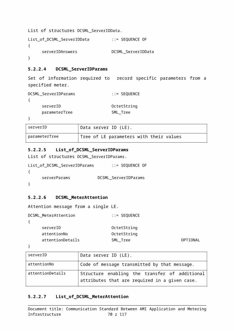
6.2.4 Example 1-5-4
6.2.4.1 Queryoffset 0 1 2 3 4 5 6 7 8 9 10 11 12 13 14 15 ascii
00000000 30 24 80 10 43 4C 49 45 4E 54 2D 56 34 56 41 35 0$€.CLIENT-V4VA500000010 4E 38 48 34 81 10 53 45 52 56 45 52 2D 38 41 32 N8H4 �.SERVER-8A200000020 4A 49 56 32 44 33 30 4F A0 12 04 10 53 45 52 56 JIV2D30O ...SERV00000030 45 52 2D 39 49 31 53 44 41 44 33 53 82 04 52 F7 ER-9I1SDAD3S‚.R÷00000040 E8 FF 83 02 5E E9 84 04 4D F0 A5 CF 85 04 4D F0 č˙�.^é„.MđĄĎ….Mđ00000050 B3 DF A6 23 04 05 31 2E 38 2E 30 04 05 32 2E 38 łß¦#..1.8.0..2.800000060 2E 30 04 05 35 2E 38 2E 30 04 05 36 2E 38 2E 30 .0..5.8.0..6.8.000000070 04 05 37 2E 38 2E 30 30 00 00 00 00 00 00 00 00 ..7.8.00........
Figure 49: Response 1-5-4 in the APDU form
SMLPublicOpen_Req {CLIENT-V4VA5N8H4,SERVER-8A2JIV2D3,
}DCMeterGetData_Req {
listserverID {SERVER-9I1SDAD3S,
}1391978751 [HEX: 52 F7 E8 FF],24297 [HEX: 5E E9],1307616719 [HEX: 4D F0 A5 CF] (Thu Jun 09 12:51:59 CEST 2011),1307620319 [HEX: 4D F0 B3 DF] (Thu Jun 09 13:51:59 CEST 2011),parameterTreePath {
1.8.0,2.8.0,5.8.0,6.8.0,7.8.0,
}}SMLPublicClose_Req {}
Figure 50: Query 1-5-4 in ASN.1 notation
Document title: Communication Standard Between AMI Application and Metering Infrastructure 70 z 94

6.2.4.2 Response
offset 0 1 2 3 4 5 6 7 8 910
11
12
13
14
15 ascii
00000000 30
24
80
10
43
4C
49
45
4E
54
2D
56
34
56
41
35
0$€.CLIENT-V4VA5
00000010 4E
38
48
34
81
10
53
45
52
56
45
52
2D
38
41
32 N8H4�.SERVER-8A2
00000020 4A
49
56
32
44
33
30
82
01
26
81
04
12
96
6D
57 JIV2D30‚.& �..–mW
00000030 82
02
02
0E
A3
23
04
05
31
2E
38
2E
30
04
05
32
‚...Ł#..1.8.0..2
00000040 2E
38
2E
30
04
05
35
2E
38
2E
30
04
05
36
2E
38
.8.0..5.8.0..6.8
00000050 2E
30
04
05
37
2E
38
2E
30
A4
81
F4
30
81
F1
80 .0..7.8.0¤ô� 0ń€�
00000060 10
53
45
52
56
45
52
2D
39
49
31
53
44
41
44
33
.SERVER-9I1SDAD3
00000070 53
A1
4B
30
0D
80
05
31
2E
38
2E
30
81
01
05
82 SˇK0.€.1.8.0 �..‚
00000080 01
01
30
0D
80
05
32
2E
38
2E
30
81
01
07
82
01 ..0.€.2.8.0 �..‚.
00000090 01
30
0D
80
05
35
2E
38
2E
30
81
01
08
82
01
01 .0.€.5.8.0 �..‚..
000000A0 30
0D
80
05
36
2E
38
2E
30
81
01
04
82
01
01
30 0.€.6.8.0 �..‚..0
000000B0 0D
80
05
37
2E
38
2E
30
81
01
01
82
01
01
A2
81 .€.7.8.0 �..‚..˘�
000000C0 8F
30
22
80
04
4D
F0
A5
CF
81
01
08
A2
17
02
02 Ź0"€.MđĄĎ �..˘...
000000D0 17
61
02
03
00
83
A0
02
03
00
8C
43
02
03
00
B3 .a... � ...ŚC...ł
000000E0 51
02
02
10
33
30
23
80
04
4D
F0
A9
53
81
01
08 Q...30#€.Mđ©S �..
000000F0 A2
18
02
03
00
CD
E3
02
02
04
92
02
03
00
94
CD
˘....Üă...’...”Ü
00000100 02
03
00
99
C8
02
03
00
9B
BC
30
20
80
04
4D
F0
...™Č...›Ľ0 €.Mđ
00000110
MOD
D7
81
01
08
A2
15
02
02
1F
1D
02
02
2A
0C
02 ¬×�..˘.......*..
00000120 02
4A
65
02
03
00
88
7D
02
02
48
D3
30
22
80
04 .Je... �}..HÓ0"€.
00000130 4D
F0
B0
5B
81
01
08
A2
17
02
03
00
C3
09
02
02 Mđ°[�..˘....Ă...
00000140 26
7E
02
03
00
E4
38
02
03
00
A3
71
02
02
58
7B
&~...ä8...Łq..X{
00000150 30
00
00
00
00
00
00
00
00
00
00
00
00
00
00
00
0...............
Figure 51: Response 1-5-4 in the APDU form
SMLPublicOpen_Res {CLIENT-V4VA5N8H4,SERVER-8A2JIV2D3,
}DCMeterGetData_Res {
311848279 [HEX: 12 96 6D 57],526 [HEX: 02 0E],parameterTreePath {
1.8.0,2.8.0,5.8.0,6.8.0,
Document title: Communication Standard Between AMI Application and Metering Infrastructure 71 z 94

7.8.0,}DCSML_ServerIDAnswers {
SERVER-9I1SDAD3S,{
SMLHeaderEntry { 1.8.0, 5, 1 }SMLHeaderEntry { 2.8.0, 7, 1 }SMLHeaderEntry { 5.8.0, 8, 1 }SMLHeaderEntry { 6.8.0, 4, 1 }SMLHeaderEntry { 7.8.0, 1, 1 }
}{
SMLProfObjPeriodEntry {1307616719 [HEX: 4D F0 A5 CF] (Thu Jun 09 12:51:59 CEST
2011),8,{
5985 [HEX: 17 61],33696 [HEX: 83 A0],35907 [HEX: 8C 43],45905 [HEX: B3 51],4147 [HEX: 10 33],
}}SMLProfObjPeriodEntry {
1307617619 [HEX: 4D F0 A9 53] (Thu Jun 09 1:06:59 PM CEST 2011),
8,{
56547 [HEX: DC E3],1170 [HEX: 04 92],38108 [HEX: 94 DC],39368 [HEX: 99 C8],39868 [HEX: 9B BC],
}}SMLProfObjPeriodEntry {
1307618519 [HEX: 4D F0 AC D7] (Thu Jun 09 13:21:59 CEST 2011),
8,{
7965 [HEX: 1F 1D],10764 [HEX: 2A 0C],19045 [HEX: 4A 65],34941 [HEX: 88 7D],18643 [HEX: 48 D3],
}}SMLProfObjPeriodEntry {
1307619419 [HEX: 4D F0 B0 5B] (Thu Jun 09 1:36:59 PM CEST 2011),
8,{
49929 [HEX: C3 09],9854 [HEX: 26 7E],58424 [HEX: E4 38],41841 [HEX: A3 71],
Document title: Communication Standard Between AMI Application and Metering Infrastructure 72 z 94

22651 [HEX: 58 7B],}
}}
}}SMLPublicClose_Res {}
Figure 52: Response 1-5-4 in ASN.1 notation
6.2.5 Example 5-1-1
6.2.5.1 Query
offset 0 1 2 3 4 5 6 7 8 910
11
12
13
14
15 ascii
00000000
30
24
80
10
43
4C
49
45
4E
54
2D
4C
4A
32
54
59
0$€.CLIENT-LJ2TY
00000010
5A
5A
4C
52
81
10
53
45
52
56
45
52
2D
4D
56
48 ZZLR �.SERVER-MVH
00000020
4F
35
37
35
43
52
30
7C
A0
5A
04
10
53
45
52
56
O575CR0| Z..SERV
00000030
45
52
2D
31
30
32
46
58
57
4F
5A
53
04
10
53
45
ER-102FXWOZS..SE
00000040
52
56
45
52
2D
35
33
32
55
56
55
51
32
51
04
10
RVER-532UVUQ2Q..
00000050
53
45
52
56
45
52
2D
30
51
33
59
41
59
36
4F
33
SERVER-0Q3YAY6O3
00000060
04
10
53
45
52
56
45
52
2D
49
47
4D
49
4A
4A
45
..SERVER-IGMIJJE
00000070
38
39
04
10
53
45
52
56
45
52
2D
42
4B
45
43
52
89..SERVER-BKECR
00000080
31
46
43
36
82
04
25
93
B7
52
83
03
00
D5
4C
84 1FC6‚.%“·R �..ŐL„
00000090
04
4D
F0
A5
CF
85
04
4D
F0
A9
53
A6
07
04
05
31
.MđĄĎ….Mđ©S¦...1
000000A0
2E
38
2E
30
30
00
00
00
00
00
00
00
00
00
00
00
.8.00..........
.Figure 53: Response 5-1-4 in the APDU form
SMLPublicOpen_Req {CLIENT-LJ2TYZZLR,SERVER-MVHO575CR,
}DCMeterGetData_Req {
listserverID {SERVER-102FXWOZS,SERVER-532UVUQ2Q,SERVER-0Q3YAY6O3,SERVER-IGMIJJE89,SERVER-BKECR1FC6,
}630437714 [HEX: 25 93 B7 52],54604 [HEX: D5 4C],1307616719 [HEX: 4D F0 A5 CF] (Thu Jun 09 12:51:59 CEST 2011),1307617619 [HEX: 4D F0 A9 53] (Thu Jun 09 1:06:59 PM CEST 2011),parameterTreePath {
1.8.0,}
}
Document title: Communication Standard Between AMI Application and Metering Infrastructure 73 z 94

SMLPublicClose_Req {}
Figure 54: Query 5-1-1 in ASN.1 notation
6.2.5.2 Responseoffset 0 1 2 3 4 5 6 7 8 9 10 11 12 13 14 15 ascii
00000000 30 24 80 10 43 4C 49 45 4E 54 2D 4C 4A 32 54 59 0$€.CLIENT-LJ2TY00000010 5A 5A 4C 52 81 10 53 45 52 56 45 52 2D 4D 56 48 ZZLR �.SERVER-MVH00000020 4F 35 37 35 43 52 30 82 01 34 81 04 14 7F 04 A6 O575CR0‚.4 �...� ¦00000030 82 03 00 C2 29 A3 07 04 05 31 2E 38 2E 30 A4 82 ‚..Â)Ł...1.8.0¤‚00000040 01 1C 30 37 80 10 53 45 52 56 45 52 2D 31 30 32 ..07€.SERVER-10200000050 46 58 57 4F 5A 53 A1 0F 30 0D 80 05 31 2E 38 2E FXWOZSˇ.0.€.1.8.00000060 30 81 01 05 82 01 01 A2 12 30 10 80 04 4D F0 A5 0�..‚..˘.0.€.MđĄ00000070 CF 81 01 08 A2 05 02 03 00 CD 79 30 37 80 10 53 Ď�..˘....Üy07€.S00000080 45 52 56 45 52 2D 35 33 32 55 56 55 51 32 51 A1 ERVER-532UVUQ2Qˇ00000090 0F 30 0D 80 05 31 2E 38 2E 30 81 01 05 82 01 01 .0.€.1.8.0 �..‚..000000A0 A2 12 30 10 80 04 4D F0 A5 CF 81 01 08 A2 05 02 ˘.0.€.MđĄĎ �..˘..000000B0 03 00 98 0E 30 37 80 10 53 45 52 56 45 52 2D 30 ..�.07€.SERVER-0000000C0 51 33 59 41 59 36 4F 33 A1 0F 30 0D 80 05 31 2E Q3YAY6O3ˇ.0.€.1.000000D0 38 2E 30 81 01 05 82 01 01 A2 12 30 10 80 04 4D 8.0 �..‚..˘.0.€.M000000E0 F0 A5 CF 81 01 08 A2 05 02 03 00 F8 A2 30 36 80 đĄĎ �..˘....ř˘06€000000F0 10 53 45 52 56 45 52 2D 49 47 4D 49 4A 4A 45 38 .SERVER-IGMIJJE800000100 39 A1 0F 30 0D 80 05 31 2E 38 2E 30 81 01 05 82 9ˇ.0.€.1.8.0 �..‚00000110 01 01 A2 11 30 0F 80 04 4D F0 A5 CF 81 01 08 A2 ..˘.0.€.MđĄĎ �..˘00000120 04 02 02 58 6D 30 37 80 10 53 45 52 56 45 52 2D ...Xm07€.SERVER-00000130 42 4B 45 43 52 31 46 43 36 A1 0F 30 0D 80 05 31 BKECR1FC6ˇ.0.€.100000140 2E 38 2E 30 81 01 05 82 01 01 A2 12 30 10 80 04 .8.0 �..‚..˘.0.€.00000150 4D F0 A5 CF 81 01 08 A2 05 02 03 00 86 D9 30 00 MđĄĎ �..˘....†Ů0.
Figure 55: Response 5-1-1 in the APDU form
SMLPublicOpen_Res {CLIENT-LJ2TYZZLR,SERVER-MVHO575CR,
}DCMeterGetData_Res {
343868582 [HEX: 14 7F 04 A6],49705 [HEX: C2 29],parameterTreePath {
1.8.0,}DCSML_ServerIDAnswers {
SERVER-102FXWOZS,{
SMLHeaderEntry { 1.8.0, 5, 1 }}{
SMLProfObjPeriodEntry {1307616719 [HEX: 4D F0 A5 CF] (Thu Jun 09 12:51:59 CEST
2011),8,{
56441 [HEX: DC 79],}
}
Document title: Communication Standard Between AMI Application and Metering Infrastructure 74 z 94

}DCSML_ServerIDAnswers {
SERVER-532UVUQ2Q,{
SMLHeaderEntry { 1.8.0, 5, 1 }}{
SMLProfObjPeriodEntry {1307616719 [HEX: 4D F0 A5 CF] (Thu Jun 09 12:51:59 CEST
2011),8,{
38926 [HEX: 98 0E],}
}}
DCSML_ServerIDAnswers {SERVER-0Q3YAY6O3,{
SMLHeaderEntry { 1.8.0, 5, 1 }}{
SMLProfObjPeriodEntry {1307616719 [HEX: 4D F0 A5 CF] (Thu Jun 09 12:51:59 CEST
2011),8,{
63650 [HEX: F8 A2],}
}}
DCSML_ServerIDAnswers {SERVER-IGMIJJE89,{
SMLHeaderEntry { 1.8.0, 5, 1 }}{
SMLProfObjPeriodEntry {1307616719 [HEX: 4D F0 A5 CF] (Thu Jun 09 12:51:59 CEST
2011),8,{
22637 [HEX: 58 6D],}
}}
DCSML_ServerIDAnswers {SERVER-BKECR1FC6,{
SMLHeaderEntry { 1.8.0, 5, 1 }}{
SMLProfObjPeriodEntry {1307616719 [HEX: 4D F0 A5 CF] (Thu Jun 09 12:51:59 CEST
2011),8,{
Document title: Communication Standard Between AMI Application and Metering Infrastructure 75 z 94

34521 [HEX: 86 D9],}
}}
}}SMLPublicClose_Res {}
Figure 56: Response 5-1-1 in ASN.1 notation
6.2.6 Example 5-1-4
6.2.6.1 Queryoffset 0 1 2 3 4 5 6 7 8 9 10 11 12 13 14 15 ascii
00000000 30 24 80 10 43 4C 49 45 4E 54 2D 4C 4A 32 54 59 0$€.CLIENT-LJ2TY00000010 5A 5A 4C 52 81 10 53 45 52 56 45 52 2D 4D 56 48 ZZLR �.SERVER-MVH00000020 4F 35 37 35 43 52 30 7C A0 5A 04 10 53 45 52 56 O575CR0| Z..SERV00000030 45 52 2D 31 30 32 46 58 57 4F 5A 53 04 10 53 45 ER-102FXWOZS..SE00000040 52 56 45 52 2D 35 33 32 55 56 55 51 32 51 04 10 RVER-532UVUQ2Q..00000050 53 45 52 56 45 52 2D 30 51 33 59 41 59 36 4F 33 SERVER-0Q3YAY6O300000060 04 10 53 45 52 56 45 52 2D 49 47 4D 49 4A 4A 45 ..SERVER-IGMIJJE00000070 38 39 04 10 53 45 52 56 45 52 2D 42 4B 45 43 52 89..SERVER-BKECR00000080 31 46 43 36 82 04 25 93 B7 52 83 03 00 D5 4C 84 1FC6‚.%“·Rƒ..ŐL„00000090 04 4D F0 A5 CF 85 04 4D F0 A9 53 A6 07 04 05 31 .MđĄĎ….Mđ©S¦...1000000A0 2E 38 2E 30 30 00 00 00 00 00 00 00 00 00 00 00 .8.00...........
Figure 57: Response 5-1-4 in the APDU form
Document title: Communication Standard Between AMI Application and Metering Infrastructure 76 z 94
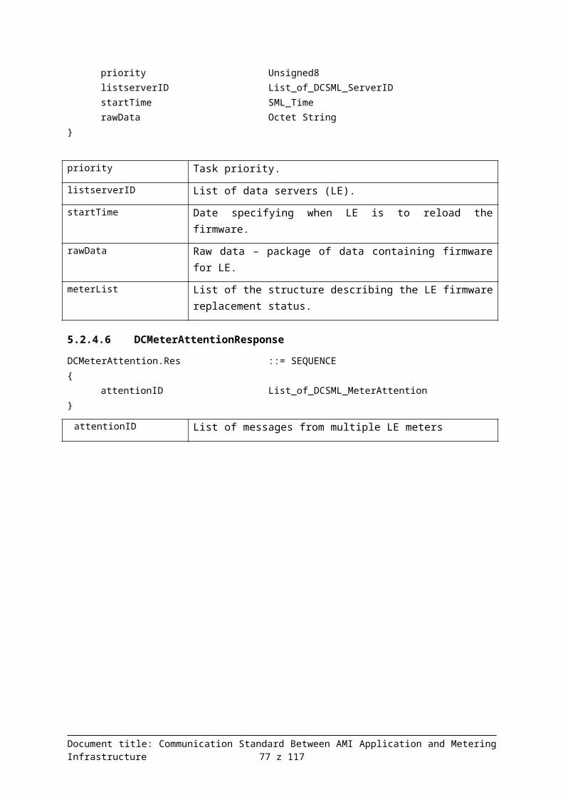
SMLPublicOpen_Req {CLIENT-LJ2TYZZLR,SERVER-MVHO575CR,
}DCMeterGetData_Req {
listserverID {SERVER-102FXWOZS,SERVER-532UVUQ2Q,SERVER-0Q3YAY6O3,SERVER-IGMIJJE89,SERVER-BKECR1FC6,
}630437714 [HEX: 25 93 B7 52],54604 [HEX: D5 4C],1307616719 [HEX: 4D F0 A5 CF] (Thu Jun 09 12:51:59 CEST 2011),1307617619 [HEX: 4D F0 A9 53] (Thu Jun 09 1:06:59 PM CEST 2011),parameterTreePath {
1.8.0,}
}SMLPublicClose_Req {}
Figure 58: Query 5-1-4 in ASN.1 notation
6.2.6.2 Responseoffset 0 1 2 3 4 5 6 7 8 9 10 11 12 13 14 15 ascii
00000000 30 24 80 10 43 4C 49 45 4E 54 2D 4C 4A 32 54 59 0$€.CLIENT-LJ2TY00000010 5A 5A 4C 52 81 10 53 45 52 56 45 52 2D 4D 56 48 ZZLR �.SERVER-MVH00000020 4F 35 37 35 43 52 30 82 01 34 81 04 14 7F 04 A6 O575CR0‚.4 �...� ¦00000030 82 03 00 C2 29 A3 07 04 05 31 2E 38 2E 30 A4 82 ‚..Â)Ł...1.8.0¤‚00000040 01 1C 30 37 80 10 53 45 52 56 45 52 2D 31 30 32 ..07€.SERVER-10200000050 46 58 57 4F 5A 53 A1 0F 30 0D 80 05 31 2E 38 2E FXWOZSˇ.0.€.1.8.00000060 30 81 01 05 82 01 01 A2 12 30 10 80 04 4D F0 A5 0�..‚..˘.0.€.MđĄ00000070 CF 81 01 08 A2 05 02 03 00 CD 79 30 37 80 10 53 Ď�..˘....Üy07€.S00000080 45 52 56 45 52 2D 35 33 32 55 56 55 51 32 51 A1 ERVER-532UVUQ2Qˇ00000090 0F 30 0D 80 05 31 2E 38 2E 30 81 01 05 82 01 01 .0.€.1.8.0 �..‚..000000A0 A2 12 30 10 80 04 4D F0 A5 CF 81 01 08 A2 05 02 ˘.0.€.MđĄĎ �..˘..000000B0 03 00 98 0E 30 37 80 10 53 45 52 56 45 52 2D 30 ..�.07€.SERVER-0000000C0 51 33 59 41 59 36 4F 33 A1 0F 30 0D 80 05 31 2E Q3YAY6O3ˇ.0.€.1.000000D0 38 2E 30 81 01 05 82 01 01 A2 12 30 10 80 04 4D 8.0 �..‚..˘.0.€.M000000E0 F0 A5 CF 81 01 08 A2 05 02 03 00 F8 A2 30 36 80 đĄĎ �..˘....ř˘06€000000F0 10 53 45 52 56 45 52 2D 49 47 4D 49 4A 4A 45 38 .SERVER-IGMIJJE800000100 39 A1 0F 30 0D 80 05 31 2E 38 2E 30 81 01 05 82 9ˇ.0.€.1.8.0 �..‚00000110 01 01 A2 11 30 0F 80 04 4D F0 A5 CF 81 01 08 A2 ..˘.0.€.MđĄĎ �..˘00000120 04 02 02 58 6D 30 37 80 10 53 45 52 56 45 52 2D ...Xm07€.SERVER-00000130 42 4B 45 43 52 31 46 43 36 A1 0F 30 0D 80 05 31 BKECR1FC6ˇ.0.€.100000140 2E 38 2E 30 81 01 05 82 01 01 A2 12 30 10 80 04 .8.0 �..‚..˘.0.€.00000150 4D F0 A5 CF 81 01 08 A2 05 02 03 00 86 D9 30 00 MđĄĎ �..˘....†Ů0.
Figure 59: Response 5-1-4 in the APDU form
SMLPublicOpen_Res {CLIENT-GO0A3OBPF,SERVER-XADE3KLQA,
}
Document title: Communication Standard Between AMI Application and Metering Infrastructure 77 z 94

DCMeterGetData_Res {2078902676 [HEX: 7B E9 89 94],8750 [HEX: 22 2E],parameterTreePath {
1.8.0,}DCSML_ServerIDAnswers {
SERVER-QS9YICBYI,{
SMLHeaderEntry { 1.8.0, 5, 1 }}{
SMLProfObjPeriodEntry {1307616718 [HEX: 4D F0 A5 CE] (Thu Jun 09 12:51:58 CEST
2011),8,{
42429 [HEX: A5 BD],}
}SMLProfObjPeriodEntry {
1307617618 [HEX: 4D F0 A9 52] (Thu Jun 09 13:06:58 CEST 2011),
8,{
58574 [HEX: E4 CE],}
}SMLProfObjPeriodEntry {
1307618518 [HEX: 4D F0 AC D6] (Thu Jun 09 13:21:58 CEST 2011),
8,{
62488 [HEX: F4 18],}
}SMLProfObjPeriodEntry {
1307619418 [HEX: 4D F0 B0 5A] (Thu Jun 09 13:36:58 CEST 2011),
8,{
12680 [HEX: 31 88],}
}}
DCSML_ServerIDAnswers {SERVER-9CSFCRDH5,{
SMLHeaderEntry { 1.8.0, 5, 1 }}{
SMLProfObjPeriodEntry {1307616718 [HEX: 4D F0 A5 CE] (Thu Jun 09 12:51:58 CEST
2011),8,{
53621 [HEX: D1 75],
Document title: Communication Standard Between AMI Application and Metering Infrastructure 78 z 94

}}SMLProfObjPeriodEntry {
1307617618 [HEX: 4D F0 A9 52] (Thu Jun 09 13:06:58 CEST 2011),
8,{
15381 [HEX: 3C 15],}
}SMLProfObjPeriodEntry {
1307618518 [HEX: 4D F0 AC D6] (Thu Jun 09 13:21:58 CEST 2011),
8,{
57326 [HEX: DF EE],}
}SMLProfObjPeriodEntry {
1307619418 [HEX: 4D F0 B0 5A] (Thu Jun 09 13:36:58 CEST 2011),
8,{
28371 [HEX: 6E D3],}
}}
DCSML_ServerIDAnswers {SERVER-2KBGFPDQA,{
SMLHeaderEntry { 1.8.0, 5, 1 }}{
SMLProfObjPeriodEntry {1307616718 [HEX: 4D F0 A5 CE] (Thu Jun 09 12:51:58 CEST
2011),8,{
2127 [HEX: 08 4F],}
}SMLProfObjPeriodEntry {
1307617618 [HEX: 4D F0 A9 52] (Thu Jun 09 13:06:58 CEST 2011),
8,{
12857 [HEX: 32 39],}
}SMLProfObjPeriodEntry {
1307618518 [HEX: 4D F0 AC D6] (Thu Jun 09 13:21:58 CEST 2011),
8,{
18283 [HEX: 47 6B],}
}
Document title: Communication Standard Between AMI Application and Metering Infrastructure 79 z 94

SMLProfObjPeriodEntry {1307619418 [HEX: 4D F0 B0 5A] (Thu Jun 09 13:36:58 CEST
2011),8,{
28557 [HEX: 6F 8D],}
}}
DCSML_ServerIDAnswers {SERVER-C0IO84PZS,{
SMLHeaderEntry { 1.8.0, 5, 1 }}{
SMLProfObjPeriodEntry {1307616718 [HEX: 4D F0 A5 CE] (Thu Jun 09 12:51:58 CEST
2011),8,{
39227 [HEX: 99 3B],}
}SMLProfObjPeriodEntry {
1307617618 [HEX: 4D F0 A9 52] (Thu Jun 09 13:06:58 CEST 2011),
8,{
44251 [HEX: AC DB],}
}SMLProfObjPeriodEntry {
1307618518 [HEX: 4D F0 AC D6] (Thu Jun 09 13:21:58 CEST 2011),
8,{
23239 [HEX: 5A C7],}
}SMLProfObjPeriodEntry {
1307619418 [HEX: 4D F0 B0 5A] (Thu Jun 09 13:36:58 CEST 2011),
8,{
24035 [HEX: 5D E3],}
}}
DCSML_ServerIDAnswers {SERVER-EQWS32GHO,{
SMLHeaderEntry { 1.8.0, 5, 1 }}{
SMLProfObjPeriodEntry {1307616718 [HEX: 4D F0 A5 CE] (Thu Jun 09 12:51:58 CEST
2011),
Document title: Communication Standard Between AMI Application and Metering Infrastructure 80 z 94
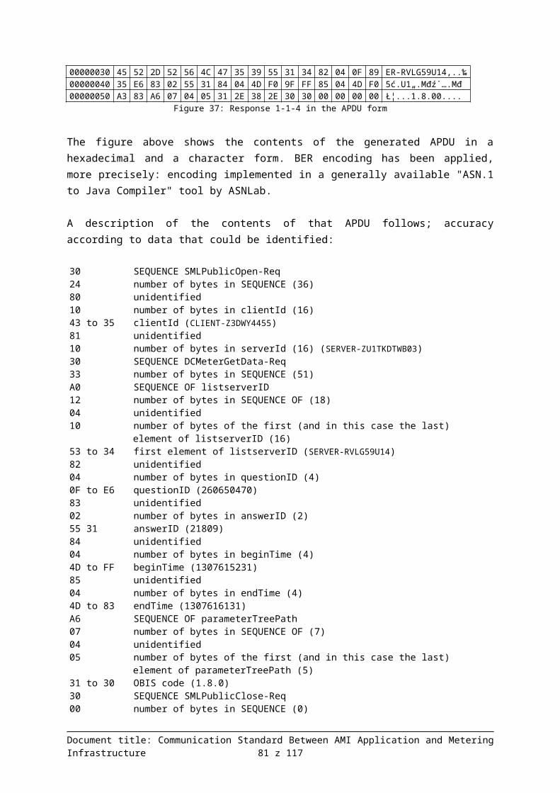
8,{
57436 [HEX: E0 5C],}
}SMLProfObjPeriodEntry {
1307617618 [HEX: 4D F0 A9 52] (Thu Jun 09 13:06:58 CEST 2011),
8,{
637 [HEX: 02 7D],}
}SMLProfObjPeriodEntry {
1307618518 [HEX: 4D F0 AC D6] (Thu Jun 09 13:21:58 CEST 2011),
8,{
51808 [HEX: CA 60],}
}SMLProfObjPeriodEntry {
1307619418 [HEX: 4D F0 B0 5A] (Thu Jun 09 13:36:58 CEST 2011),
8,{
8985 [HEX: 23 19],}
}}
}}SMLPublicClose_Res {}
Figure 60: Response 5-1-4 in ASN.1 notation
6.2.7 Example 5-5-1
6.2.7.1 Queryoffset 0 1 2 3 4 5 6 7 8 9 10 11 12 13 14 15 ascii
00000000 30 24 80 10 43 4C 49 45 4E 54 2D 45 46 42 46 33 0$€.CLIENT-EFBF300000010 33 4C 56 33 81 10 53 45 52 56 45 52 2D 54 50 41 3LV3 �.SERVER-TPA00000020 4B 47 4E 43 43 45 30 81 98 A0 5A 04 10 53 45 52 KGNCCE0˜� Z..SER00000030 56 45 52 2D 39 53 32 50 45 4F 34 4E 46 04 10 53 VER-9S2PEO4NF..S00000040 45 52 56 45 52 2D 41 43 49 58 47 57 35 4E 57 04 ERVER-ACIXGW5NW.00000050 10 53 45 52 56 45 52 2D 35 50 34 4E 52 38 32 55 .SERVER-5P4NR82U00000060 30 04 10 53 45 52 56 45 52 2D 41 31 57 32 52 33 0..SERVER-A1W2R300000070 46 56 41 04 10 53 45 52 56 45 52 2D 48 4B 38 5A FVA..SERVER-HK8Z00000080 30 4C 32 45 49 82 04 23 80 E1 43 83 03 00 F4 B4 0L2EI‚.#€áC �..ô´00000090 84 04 4D F0 A5 CE 85 04 4D F0 A9 52 A6 23 04 05 „.MđĄÎ….Mđ©R¦#..000000A0 31 2E 38 2E 30 04 05 32 2E 38 2E 30 04 05 35 2E 1.8.0..2.8.0..5.000000B0 38 2E 30 04 05 36 2E 38 2E 30 04 05 37 2E 38 2E 8.0..6.8.0..7.8.000000C0 30 30 00 00 00 00 00 00 00 00 00 00 00 00 00 00 00..............
Figure 61: Response 5-5-4 in the APDU form
Document title: Communication Standard Between AMI Application and Metering Infrastructure 81 z 94

SMLPublicOpen_Req {CLIENT-EFBF33LV3,SERVER-TPAKGNCCE,
}DCMeterGetData_Req {
listserverID {SERVER-9S2PEO4NF,SERVER-ACIXGW5NW,SERVER-5P4NR82U0,SERVER-A1W2R3FVA,SERVER-HK8Z0L2EI,
}595648835 [HEX: 23 80 E1 43],62644 [HEX: F4 B4],1307616718 [HEX: 4D F0 A5 CE] (Thu Jun 09 12:51:58 CEST 2011),1307617618 [HEX: 4D F0 A9 52] (Thu Jun 09 13:06:58 CEST 2011),parameterTreePath {
1.8.0,2.8.0,5.8.0,6.8.0,7.8.0,
}}SMLPublicClose_Req {}
Figure 62: Query 5-5-1 in ASN.1 notation
6.2.7.2 Responseoffset 0 1 2 3 4 5 6 7 8 9 10 11 12 13 14 15 ascii
00000000 30 24 80 10 43 4C 49 45 4E 54 2D 45 46 42 46 33 0$€.CLIENT-EFBF300000010 33 4C 56 33 81 10 53 45 52 56 45 52 2D 54 50 41 3LV3 �.SERVER-TPA00000020 4B 47 4E 43 43 45 30 82 02 DB 81 04 1A 14 D7 12 KGNCCE0‚.Ű �...×.00000030 82 02 4E BD A3 23 04 05 31 2E 38 2E 30 04 05 32 ‚.N˝Ł#..1.8.0..200000040 2E 38 2E 30 04 05 35 2E 38 2E 30 04 05 36 2E 38 .8.0..5.8.0..6.800000050 2E 30 04 05 37 2E 38 2E 30 A4 82 02 A8 30 81 86 .0..7.8.0¤‚.¨0†�00000060 80 10 53 45 52 56 45 52 2D 39 53 32 50 45 4F 34 €.SERVER-9S2PEO400000070 4E 46 A1 4B 30 0D 80 05 31 2E 38 2E 30 81 01 05 NFˇK0.€.1.8.0 �..00000080 82 01 01 30 0D 80 05 32 2E 38 2E 30 81 01 07 82 ‚..0.€.2.8.0 �..‚00000090 01 01 30 0D 80 05 35 2E 38 2E 30 81 01 08 82 01 ..0.€.5.8.0 �..‚.000000A0 01 30 0D 80 05 36 2E 38 2E 30 81 01 04 82 01 01 .0.€.6.8.0 �..‚..000000B0 30 0D 80 05 37 2E 38 2E 30 81 01 01 82 01 01 A2 0.€.7.8.0 �..‚..˘000000C0 25 30 23 80 04 4D F0 A5 CE 81 01 08 A2 18 02 03 %0#€.MđĄÎ �..˘...000000D0 00 82 05 02 02 23 58 02 03 00 D1 9F 02 03 00 E5 .‚...#X...Ńź...ĺ000000E0 1C 02 03 00 B9 24 30 81 84 80 10 53 45 52 56 45 ....ą$0„€� .SERVE000000F0 52 2D 41 43 49 58 47 57 35 4E 57 A1 4B 30 0D 80 R-ACIXGW5NWˇK0.€00000100 05 31 2E 38 2E 30 81 01 05 82 01 01 30 0D 80 05 .1.8.0 �..‚..0.€.00000110 32 2E 38 2E 30 81 01 07 82 01 01 30 0D 80 05 35 2.8.0 �..‚..0.€.500000120 2E 38 2E 30 81 01 08 82 01 01 30 0D 80 05 36 2E .8.0 �..‚..0.€.6.00000130 38 2E 30 81 01 04 82 01 01 30 0D 80 05 37 2E 38 8.0 �..‚..0.€.7.800000140 2E 30 81 01 01 82 01 01 A2 23 30 21 80 04 4D F0 .0�..‚..˘#0!€.Mđ00000150 A5 CE 81 01 08 A2 16 02 02 02 18 02 03 00 E8 87 ĄÎ�..˘........č‡00000160 02 03 00 EC A2 02 02 5C 4F 02 02 24 94 30 81 85 ...ě˘..\O..$”0…�00000170 80 10 53 45 52 56 45 52 2D 35 50 34 4E 52 38 32 €.SERVER-5P4NR8200000180 55 30 A1 4B 30 0D 80 05 31 2E 38 2E 30 81 01 05 U0ˇK0.€.1.8.0 �..
Document title: Communication Standard Between AMI Application and Metering Infrastructure 82 z 94

00000190 82 01 01 30 0D 80 05 32 2E 38 2E 30 81 01 07 82 ‚..0.€.2.8.0 �..‚000001A0 01 01 30 0D 80 05 35 2E 38 2E 30 81 01 08 82 01 ..0.€.5.8.0 �..‚.000001B0 01 30 0D 80 05 36 2E 38 2E 30 81 01 04 82 01 01 .0.€.6.8.0 �..‚..000001C0 30 0D 80 05 37 2E 38 2E 30 81 01 01 82 01 01 A2 0.€.7.8.0 �..‚..˘000001D0 24 30 22 80 04 4D F0 A5 CE 81 01 08 A2 17 02 02 $0"€.MđĄÎ �..˘...000001E0 74 EF 02 02 78 48 02 03 00 BE B9 02 03 00 CB A7 tď..xH...ľą...˧000001F0 02 03 00 C5 5D 30 81 84 80 10 53 45 52 56 45 52 ...Ĺ]0„€� .SERVER00000200 2D 41 31 57 32 52 33 46 56 41 A1 4B 30 0D 80 05 -A1W2R3FVAˇK0.€.00000210 31 2E 38 2E 30 81 01 05 82 01 01 30 0D 80 05 32 1.8.0 �..‚..0.€.200000220 2E 38 2E 30 81 01 07 82 01 01 30 0D 80 05 35 2E .8.0 �..‚..0.€.5.
Figure 63: Response 5-5-1 in the APDU form
SMLPublicOpen_Res {CLIENT-EFBF33LV3,SERVER-TPAKGNCCE,
}DCMeterGetData_Res {
437573394 [HEX: 1A 14 D7 12],20157 [HEX: 4E BD],parameterTreePath {
1.8.0,2.8.0,5.8.0,6.8.0,7.8.0,
}DCSML_ServerIDAnswers {
SERVER-9S2PEO4NF,{
SMLHeaderEntry { 1.8.0, 5, 1 }SMLHeaderEntry { 2.8.0, 7, 1 }SMLHeaderEntry { 5.8.0, 8, 1 }SMLHeaderEntry { 6.8.0, 4, 1 }SMLHeaderEntry { 7.8.0, 1, 1 }
}{
SMLProfObjPeriodEntry {1307616718 [HEX: 4D F0 A5 CE] (Thu Jun 09 12:51:58 CEST
2011),8,{
33285 [HEX: 82 05],9048 [HEX: 23 58],53663 [HEX: D1 9F],58652 [HEX: E5 1C],47396 [HEX: B9 24],
}}
}DCSML_ServerIDAnswers {
SERVER-ACIXGW5NW,{
SMLHeaderEntry { 1.8.0, 5, 1 }SMLHeaderEntry { 2.8.0, 7, 1 }SMLHeaderEntry { 5.8.0, 8, 1 }
Document title: Communication Standard Between AMI Application and Metering Infrastructure 83 z 94
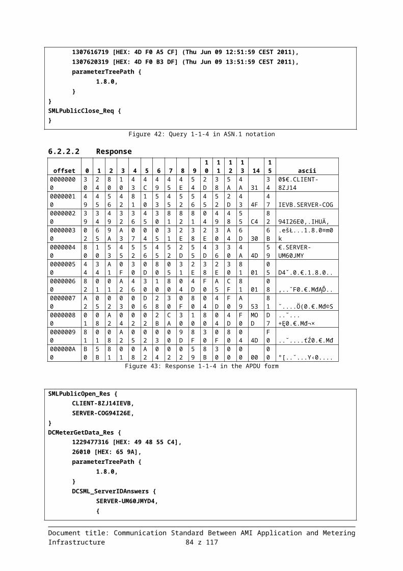
SMLHeaderEntry { 6.8.0, 4, 1 }SMLHeaderEntry { 7.8.0, 1, 1 }
}{
SMLProfObjPeriodEntry {1307616718 [HEX: 4D F0 A5 CE] (Thu Jun 09 12:51:58 CEST
2011),8,{
536 [HEX: 02 18],59527 [HEX: E8 87],60578 [HEX: EC A2],23631 [HEX: 5C 4F],9364 [HEX: 24 94],
}}
}DCSML_ServerIDAnswers {
SERVER-5P4NR82U0,{
SMLHeaderEntry { 1.8.0, 5, 1 }SMLHeaderEntry { 2.8.0, 7, 1 }SMLHeaderEntry { 5.8.0, 8, 1 }SMLHeaderEntry { 6.8.0, 4, 1 }SMLHeaderEntry { 7.8.0, 1, 1 }
}{
SMLProfObjPeriodEntry {1307616718 [HEX: 4D F0 A5 CE] (Thu Jun 09 12:51:58 CEST
2011),8,{
29935 [HEX: 74 EF],30792 [HEX: 78 48],48825 [HEX: BE B9],52135 [HEX: CB A7],50525 [HEX: C5 5D],
}}
}DCSML_ServerIDAnswers {
SERVER-A1W2R3FVA,{
SMLHeaderEntry { 1.8.0, 5, 1 }SMLHeaderEntry { 2.8.0, 7, 1 }SMLHeaderEntry { 5.8.0, 8, 1 }SMLHeaderEntry { 6.8.0, 4, 1 }SMLHeaderEntry { 7.8.0, 1, 1 }
}{
SMLProfObjPeriodEntry {1307616718 [HEX: 4D F0 A5 CE] (Thu Jun 09 12:51:58 CEST
2011),8,{
24847 [HEX: 61 0F],58828 [HEX: E5 CC],
Document title: Communication Standard Between AMI Application and Metering Infrastructure 84 z 94

26551 [HEX: 67 B7],3180 [HEX: 0C 6C],41280 [HEX: A1 40],
}}
}DCSML_ServerIDAnswers {
SERVER-HK8Z0L2EI,{
SMLHeaderEntry { 1.8.0, 5, 1 }SMLHeaderEntry { 2.8.0, 7, 1 }SMLHeaderEntry { 5.8.0, 8, 1 }SMLHeaderEntry { 6.8.0, 4, 1 }SMLHeaderEntry { 7.8.0, 1, 1 }
}{
SMLProfObjPeriodEntry {1307616718 [HEX: 4D F0 A5 CE] (Thu Jun 09 12:51:58 CEST
2011),8,{
63424 [HEX: F7 C0],45317 [HEX: B1 05],60807 [HEX: ED 87],8757 [HEX: 22 35],49005 [HEX: BF 6D],
}}
}}
}SMLPublicClose_Res {}
Figure 64: Response 5-5-1 in ASN.1 notation
6.2.8 Example 5-5-4
6.2.8.1 Queryoffset 0 1 2 3 4 5 6 7 8 9 10 11 12 13 14 15 ascii
00000000 30 24 80 10 43 4C 49 45 4E 54 2D 4C 36 48 42 45 0$€.CLIENT-L6HBE00000010 43 56 43 52 81 10 53 45 52 56 45 52 2D 5A 36 36 CVCR �.SERVER-Z6600000020 38 4B 33 50 48 37 30 81 98 A0 5A 04 10 53 45 52 8K3PH70 �� Z..SER00000030 56 45 52 2D 39 43 33 35 34 59 41 46 57 04 10 53 VER-9C354YAFW..S00000040 45 52 56 45 52 2D 36 47 43 4C 49 43 43 44 31 04 ERVER-6GCLICCD1.00000050 10 53 45 52 56 45 52 2D 4F 44 5A 38 39 4A 4B 4B .SERVER-ODZ89JKK00000060 44 04 10 53 45 52 56 45 52 2D 55 50 42 33 35 57 D..SERVER-UPB35W00000070 57 58 57 04 10 53 45 52 56 45 52 2D 49 43 5A 39 WXW..SERVER-ICZ900000080 49 34 55 30 30 82 04 3E 8D A8 35 83 03 00 C9 13 I4U00‚.>Ť¨5 �..É.00000090 84 04 4D F0 A5 CE 85 04 4D F0 B3 DE A6 23 04 05 „.MđĄÎ….MđłŢ¦#..000000A0 31 2E 38 2E 30 04 05 32 2E 38 2E 30 04 05 35 2E 1.8.0..2.8.0..5.000000B0 38 2E 30 04 05 36 2E 38 2E 30 04 05 37 2E 38 2E 8.0..6.8.0..7.8.000000C0 30 30 00 00 00 00 00 00 00 00 00 00 00 00 00 00 00..............
Figure 65: Response 5-5-4 in the APDU form
SMLPublicOpen_Req {
Document title: Communication Standard Between AMI Application and Metering Infrastructure 85 z 94

CLIENT-L6HBECVCR,SERVER-Z668K3PH7,
}DCMeterGetData_Req {
listserverID {SERVER-9C354YAFW,SERVER-6GCLICCD1,SERVER-ODZ89JKKD,SERVER-UPB35WWXW,SERVER-ICZ9I4U00,
}1049471029 [HEX: 3E 8D A8 35],51475 [HEX: C9 13],1307616718 [HEX: 4D F0 A5 CE] (Thu Jun 09 12:51:58 CEST 2011),1307620318 [HEX: 4D F0 B3 DE] (Thu Jun 09 13:51:58 CEST 2011),parameterTreePath {
1.8.0,2.8.0,5.8.0,6.8.0,7.8.0,
}}SMLPublicClose_Req {}
Figure 66: Query 5-5-4 in ASN.1 notation
6.2.8.2 Response
offset 0 1 2 3 4 5 6 7 8 910
11
12
13 14
15 ascii
00000000
30 24
80
10
43
4C
49
45
4E
54
2D
4C
36
48 42
45
0$€.CLIENT-L6HBE
00000010
43 56
43
52
81
10
53
45
52
56
45
52
2D
5A 36
36 CVCR �.SERVER-Z66
00000020
38 4B
33
50
48
37
30
82
04
EC
81
04
69
8A D5
E5 8K3PH70‚.ě �.iŠŐĺ
00000030
82 02
21
A1
A3
23
04
05
31
2E
38
2E
30
04 05
32
‚.!ˇŁ#..1.8.0..2
00000040
2E 38
2E
30
04
05
35
2E
38
2E
30
04
05
36 2E
38
.8.0..5.8.0..6.8
00000050
2E 30
04
05
37
2E
38
2E
30
A4
82
04
B9
30 81
EE .0..7.8.0¤‚.ą0î�
00000060
80 10
53
45
52
56
45
52
2D
39
43
33
35
34 59
41
€.SERVER-9C354YA
00000070
46 57
A1
4B
30
0D
80
05
31
2E
38
2E
30
81 01
05 FWˇK0.€.1.8.0 �..
00000080
82 01
01
30
0D
80
05
32
2E
38
2E
30
81
01 07
82 ‚..0.€.2.8.0 �..‚
00000090
01 01
30
0D
80
05
35
2E
38
2E
30
81
01
08 82
01 ..0.€.5.8.0 �..‚.
000000A0
01 30
0D
80
05
36
2E
38
2E
30
81
01
04
82 01
01 .0.€.6.8.0 �..‚..
000000B0
30 0D
80
05
37
2E
38
2E
30
81
01
01
82
01 01
A2 0.€.7.8.0 �..‚..˘
000000C0
81 8C
30
21
80
04
4D
F0
A5
CE
81
01
08
A2 16
02 �Ś0!€.MđĄÎ �..˘..
000000D0
02 46
C2
02
02
49
31
02
02
59
F9
02
03
00 AB
52
.FÂ..I1..Yů...«R
000000E0
02 03
00
F4
B8
30
21
80
04
4D
F0
A9
52
81 01
08 ...ô¸0!€.Mđ©R �..
000000F0
A2 16
02
03
00
F2
18
02
02
37
37
02
02
53 44
02
˘....ň...77..SD.
Document title: Communication Standard Between AMI Application and Metering Infrastructure 86 z 94

00000100
02 57
2E
02
03
00
A6
9C
30
21
80
04
4D
F0
MOD
D6
.W....¦ś0!€.Mđ¬Ö
00000110
81 01
08
A2
16
02
02
77
DB
02
03
00
84
A8 02
02 �..˘...wŰ...„¨..
00000120
78 45
02
03
00
FA
3D
02
02
00
CC
30
21
80 04
4D
xE...ú=...Ě0!€.M
00000130
F0 B0
5A
81
01
08
A2
16
02
02
2F
1D
02
02 4C
7E đ°Z �..˘.../...L~
00000140
02 02
1C
F9
02
03
00
F2
C6
02
03
00
88
8A 30
81 ...ů...ňĆ...Š� 0�
00000150
F1 80
10
53
45
52
56
45
52
2D
36
47
43
4C 49
43
ń€.SERVER-6GCLIC
00000160
43 44
31
A1
4B
30
0D
80
05
31
2E
38
2E
30 81
01 CD1ˇK0.€.1.8.0 �.
00000170
05 82
01
01
30
0D
80
05
32
2E
38
2E
30
81 01
07 .‚..0.€.2.8.0 �..
00000180
82 01
01
30
0D
80
05
35
2E
38
2E
30
81
01 08
82 ‚..0.€.5.8.0 �..‚
00000190
01 01
30
0D
80
05
36
2E
38
2E
30
81
01
04 82
01 ..0.€.6.8.0 �..‚.
000001A0
01 30
0D
80
05
37
2E
38
2E
30
81
01
01
82 01
01 .0.€.7.8.0 �..‚..
000001B0
A2 81
8F
30
24
80
04
4D
F0
A5
CE
81
01
08 A2
19 ˘Ź� 0$€.MđĄÎ�..˘.
000001C0
02 03
00
DD
1C
02
03
00
9A
56
02
03
00
A6 CA
02
...Ý....šV...¦Ę
.000001D0
03 00
87
92
02
03
00
91
C3
30
20
80
04
4D F0
A9
..‡’...‘Ă0 €.Mđ©
000001E0
52 81
01
08
A2
15
02
02
69
9B
02
02
51
C2 02
03 R�..˘...i›..QÂ..
000001F0
00 EE
F9
02
02
49
A8
02
02
29
65
30
21
80 04
4D
.îů..I¨..)e0!€.M
00000200
F0
MOD
D6
81
01
08
A2
16
02
02
2E
9B
02
03 00
F1 đ¬Ö �..˘....›...ń
00000210
7D 02
02
24
DD
02
02
4F
EE
02
03
00
AB
8D 30
22
}..$Ý..Oî...«Ť0"
00000220
80 04
4D
F0
B0
5A
81
01
08
A2
17
02
03
00 E3
90 €.Mđ°Z �..˘....ă�
Figure 67: Response 5-5-4 in the APDU form
Document title: Communication Standard Between AMI Application and Metering Infrastructure 87 z 94

SMLPublicOpen_Res {CLIENT-L6HBECVCR,SERVER-Z668K3PH7,
}DCMeterGetData_Res {
1770706405 [HEX: 69 8A D5 E5],8609 [HEX: 21 A1],parameterTreePath {
1.8.0,2.8.0,5.8.0,6.8.0,7.8.0,
}DCSML_ServerIDAnswers {
SERVER-9C354YAFW,{
SMLHeaderEntry { 1.8.0, 5, 1 }SMLHeaderEntry { 2.8.0, 7, 1 }SMLHeaderEntry { 5.8.0, 8, 1 }SMLHeaderEntry { 6.8.0, 4, 1 }SMLHeaderEntry { 7.8.0, 1, 1 }
}{
SMLProfObjPeriodEntry {1307616718 [HEX: 4D F0 A5 CE] (Thu Jun 09 12:51:58 CEST
2011),8,{
18114 [HEX: 46 C2],18737 [HEX: 49 31],23033 [HEX: 59 F9],43858 [HEX: AB 52],62648 [HEX: F4 B8],
}}SMLProfObjPeriodEntry {
1307617618 [HEX: 4D F0 A9 52] (Thu Jun 09 13:06:58 CEST 2011),
8,{
61976 [HEX: F2 18],14135 [HEX: 37 37],21316 [HEX: 53 44],22318 [HEX: 57 2E],42652 [HEX: A6 9C],
}}SMLProfObjPeriodEntry {
1307618518 [HEX: 4D F0 AC D6] (Thu Jun 09 13:21:58 CEST 2011),
8,{
30683 [HEX: 77 DB],33960 [HEX: 84 A8],
Document title: Communication Standard Between AMI Application and Metering Infrastructure 88 z 94

30789 [HEX: 78 45],64061 [HEX: FA 3D],204 [HEX: CC],
}}SMLProfObjPeriodEntry {
1307619418 [HEX: 4D F0 B0 5A] (Thu Jun 09 13:36:58 CEST 2011),
8,{
12061 [HEX: 2F 1D],19582 [HEX: 4C 7E],7417 [HEX: 1C F9],62150 [HEX: F2 C6],34954 [HEX: 88 8A],
}}
}DCSML_ServerIDAnswers {
SERVER-6GCLICCD1,{
SMLHeaderEntry { 1.8.0, 5, 1 }SMLHeaderEntry { 2.8.0, 7, 1 }SMLHeaderEntry { 5.8.0, 8, 1 }SMLHeaderEntry { 6.8.0, 4, 1 }SMLHeaderEntry { 7.8.0, 1, 1 }
}{
SMLProfObjPeriodEntry {1307616718 [HEX: 4D F0 A5 CE] (Thu Jun 09 12:51:58 CEST
2011),8,{
56604 [HEX: DD 1C],39510 [HEX: 9A 56],42698 [HEX: A6 CA],34706 [HEX: 87 92],37315 [HEX: 91 C3],
}}SMLProfObjPeriodEntry {
1307617618 [HEX: 4D F0 A9 52] (Thu Jun 09 13:06:58 CEST 2011),
8,{
27035 [HEX: 69 9B],20930 [HEX: 51 C2],61177 [HEX: EE F9],18856 [HEX: 49 A8],10597 [HEX: 29 65],
}}SMLProfObjPeriodEntry {
1307618518 [HEX: 4D F0 AC D6] (Thu Jun 09 13:21:58 CEST 2011),
8,{
Document title: Communication Standard Between AMI Application and Metering Infrastructure 89 z 94

11931 [HEX: 2E 9B],61821 [HEX: F1 7D],9437 [HEX: 24 DD],20462 [HEX: 4F EE],43917 [HEX: AB 8D],
}}SMLProfObjPeriodEntry {
1307619418 [HEX: 4D F0 B0 5A] (Thu Jun 09 13:36:58 CEST 2011),
8,{
58256 [HEX: E3 90],15518 [HEX: 3C 9E],40582 [HEX: 9E 86],40451 [HEX: 9E 03],31787 [HEX: 7C 2B],
}}
}DCSML_ServerIDAnswers {
SERVER-ODZ89JKKD,{
SMLHeaderEntry { 1.8.0, 5, 1 }SMLHeaderEntry { 2.8.0, 7, 1 }SMLHeaderEntry { 5.8.0, 8, 1 }SMLHeaderEntry { 6.8.0, 4, 1 }SMLHeaderEntry { 7.8.0, 1, 1 }
}{
SMLProfObjPeriodEntry {1307616718 [HEX: 4D F0 A5 CE] (Thu Jun 09 12:51:58 CEST
2011),8,{
17488 [HEX: 44 50],52224 [HEX: CC],41762 [HEX: A3 22],17906 [HEX: 45 F2],38778 [HEX: 97 7A],
}}SMLProfObjPeriodEntry {
1307617618 [HEX: 4D F0 A9 52] (Thu Jun 09 13:06:58 CEST 2011),
8,{
6706 [HEX: 1A 32],40163 [HEX: 9C E3],13280 [HEX: 33 E0],61217 [HEX: EF 21],17106 [HEX: 42 D2],
}}SMLProfObjPeriodEntry {
1307618518 [HEX: 4D F0 AC D6] (Thu Jun 09 13:21:58 CEST 2011),
Document title: Communication Standard Between AMI Application and Metering Infrastructure 90 z 94

8,{
16208 [HEX: 3F 50],26068 [HEX: 65 D4],14902 [HEX: 3A 36],39920 [HEX: 9B F0],26979 [HEX: 69 63],
}}SMLProfObjPeriodEntry {
1307619418 [HEX: 4D F0 B0 5A] (Thu Jun 09 13:36:58 CEST 2011),
8,{
28938 [HEX: 71 0A],874 [HEX: 03 6A],27005 [HEX: 69 7D],56566 [HEX: DC F6],30630 [HEX: 77 A6],
}}
}DCSML_ServerIDAnswers {
SERVER-UPB35WWXW,{
SMLHeaderEntry { 1.8.0, 5, 1 }SMLHeaderEntry { 2.8.0, 7, 1 }SMLHeaderEntry { 5.8.0, 8, 1 }SMLHeaderEntry { 6.8.0, 4, 1 }SMLHeaderEntry { 7.8.0, 1, 1 }
}{
SMLProfObjPeriodEntry {1307616718 [HEX: 4D F0 A5 CE] (Thu Jun 09 12:51:58 CEST
2011),8,{
37388 [HEX: 92 0C],45669 [HEX: B2 65],61276 [HEX: EF 5C],12436 [HEX: 30 94],46896 [HEX: B7 30],
}}SMLProfObjPeriodEntry {
1307617618 [HEX: 4D F0 A9 52] (Thu Jun 09 13:06:58 CEST 2011),
8,{
49294 [HEX: C0 8E],23480 [HEX: 5B B8],7800 [HEX: 1E 78],28070 [HEX: 6D A6],18557 [HEX: 48 7D],
}}SMLProfObjPeriodEntry {
1307618518 [HEX: 4D F0 AC D6] (Thu Jun 09 13:21:58 CEST
Document title: Communication Standard Between AMI Application and Metering Infrastructure 91 z 94
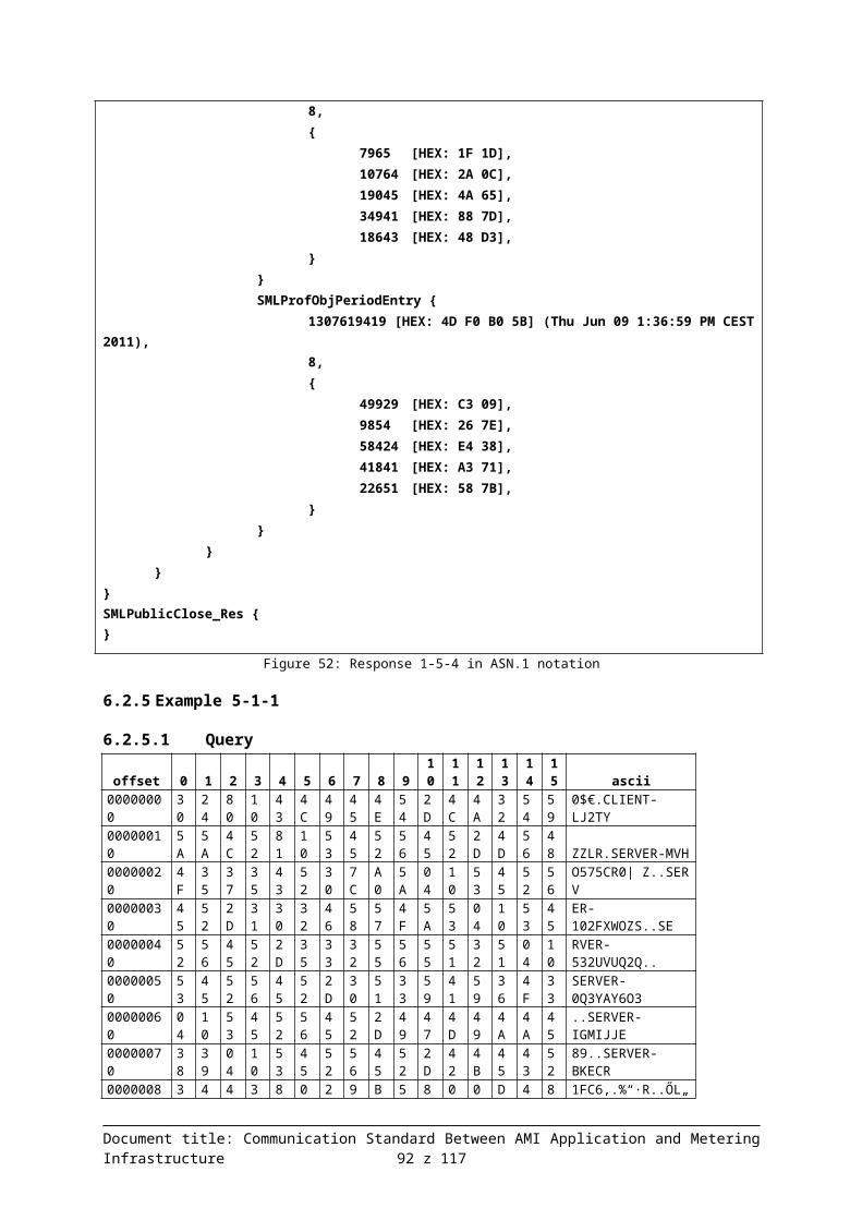
2011),8,{
52907 [HEX: CE AB],40185 [HEX: 9C F9],8909 [HEX: 22 CD],10991 [HEX: 2A EF],60658 [HEX: EC F2],
}}SMLProfObjPeriodEntry {
1307619418 [HEX: 4D F0 B0 5A] (Thu Jun 09 13:36:58 CEST 2011),
8,{
42543 [HEX: A6 2F],51178 [HEX: C7 EA],53586 [HEX: D1 52],55569 [HEX: D9 11],64530 [HEX: FC 12],
}}
}DCSML_ServerIDAnswers {
SERVER-ICZ9I4U00,{
SMLHeaderEntry { 1.8.0, 5, 1 }SMLHeaderEntry { 2.8.0, 7, 1 }SMLHeaderEntry { 5.8.0, 8, 1 }SMLHeaderEntry { 6.8.0, 4, 1 }SMLHeaderEntry { 7.8.0, 1, 1 }
}{
SMLProfObjPeriodEntry {1307616718 [HEX: 4D F0 A5 CE] (Thu Jun 09 12:51:58 CEST
2011),8,{
11298 [HEX: 2C 22],29078 [HEX: 71 96],28706 [HEX: 70 22],19155 [HEX: 4A D3],30849 [HEX: 78 81],
}}SMLProfObjPeriodEntry {
1307617618 [HEX: 4D F0 A9 52] (Thu Jun 09 13:06:58 CEST 2011),
8,{
58615 [HEX: E4 F7],61694 [HEX: F0 FE],8230 [HEX: 20 26],22636 [HEX: 58 6C],15448 [HEX: 3C 58],
}}
Document title: Communication Standard Between AMI Application and Metering Infrastructure 92 z 94

SMLProfObjPeriodEntry {1307618518 [HEX: 4D F0 AC D6] (Thu Jun 09 13:21:58 CEST
2011),8,{
15493 [HEX: 3C 85],52823 [HEX: CE 57],54491 [HEX: D4 DB],34185 [HEX: 85 89],5962 [HEX: 17 4A],
}}SMLProfObjPeriodEntry {
1307619418 [HEX: 4D F0 B0 5A] (Thu Jun 09 13:36:58 CEST 2011),
8,{
28791 [HEX: 70 77],22704 [HEX: 58 B0],1492 [HEX: 05 D4],13972 [HEX: 36 94],16694 [HEX: 41 36],
}}
}}
}SMLPublicClose_Res {}
Figure 68: Response 5-5-4 in ASN.1 notation
Document title: Communication Standard Between AMI Application and Metering Infrastructure 93 z 94

Document title: Communication Standard Between AMI Application and Metering Infrastructure 94 z 94