TECHNOTRADE LTD - solutions for petrol stations, oil stations, gas stations

w
NOVEMBER 1935
Vol. 1
15 CENTS
U.S.A.
METAL
20 cents in Canada
No. 2
GLASS
1111111=111=11.
REVIEW OF 1936 ALL -WAVE RECEIVERS;'
Reinartz Rotary Beam Aerial Improved S. W. Station List
New "Long Lines" Oscillator
Professional All -Wave Receiver Engineers Discuss Broadcasting The Silver Masterpiece IV
BOUCK - BEAT NOTE - LESTER - GRANGER - SILVER - TUMMONDS - HINDS
L.TRA SHORT AND SHORT WAVE BROADCAST AND LONG WAVE
www.americanradiohistory.com

10-60+0N 0-E0+o 9Ep268
5 Toy v ES^s
R AL1. W Av
AOto P,,E ,,E N
ZOO FF GtY
NON YORK RK
TIEW ,rpRR
Oct 22
1935
Deer Reader:
Thank u
your our wonderful I f u l r e s o f
to o our L r
first
ALL
teD p , ri
dsfett áe l
have told
us
our is
lraa9
I want you
know or or gani z 9
aonot intend
o rest
QUrels,i is
e ad
does e a"ed in
ge urinG and
for i edi-
torial
ti e ' t in
every en e of the
word
be e
assured of
ce s
Our aim is
to make ALL
VINO RADIO
the bes t M. 1
.
a2 ine in
tte s of praise ar
gi9atly ap pra-
ackn owledsed t oFs
ci ateg bat it is
ur sug estionsand
criticism
that
w a1 é
ate rially assist us in reaclins
tri Joal let ' c
b them'
In spite
f ac tnat
our circulation
de-
partment
made eQery effort
a comp lete d dis-
tribution
was, on our issue,
geci ded s1 orL
-
o°u
ited tates
To avoid
risk of
missing aigle
issue
is magazine, tet
m e s
at you
single us your ub9 r toromTly
0cour9 ,
this is a
savins ou ,
as 1e price is $1 50
per year.
Again m Átn
anks to you
fa y r overwbelmjnó
reception
of
NTD RÑIO
rdially 6".3 Ci °
_G..-e---"r--r__-
son
d
MAGp,y1NÑ `°NG `NA'r
PL 6R°ADCPST
P NASOó t pvE
TaA sN°n NG
www.americanradiohistory.com

halmod ger a 4.§mon9me to show how easy it is to learn at home in spare time to fill a
.1. E. SMITH, President. Na- tional Radio Institute, Wash- ington, D. C. -the man who has directed the training of more men for the Radio indus- try than any other man in America.
SET SERVICING has paid many N.It.I. men $5, $10, $15 a week extra for their spare lime. Full time men make as much as $30. $50, $75 a week.
BROADCASTING STATIONS employ many technically trained men for interesting. fascinating Jobs paying up to $100 a week.
GET MY FREE LESSON on Radio Servicing Tips
l'll prove that my training is practical, money -making infor- mation. that it is easy to under- stand -that it is just what you need to master Radio. My sample lesson text, "Radio Re- ceiving Troubles -the Cause and Remedy" covers a long list of Radio receiver troubles in A. C.. D. C.. battery. universal, auto. T. R. F.. super- hetero- dyne, all -wave, and other types of sets. And a cross reference system gives you the probable cause and a quick way to locate and remedy these set troubles. A special section is devoted to receiver check -up. alignment. balancing. neutralizing and testing. Get this lesson. Free. No obligation. Just mail Coupon.
Clip and mail the coupon, I'll send you a FREE lesson. I'll show you that Radio is fascinating; that I give you practical money -making informa- tion, easy to learn, easy to put into use. See for yourself why many men with less than a grammar school education and no Radio experience are now making good money as Radio Experts. Get the facts about Radio's spare time and full time job opportunities. Mail the coupon now.
Many Radio Experts make $30, $50, $75 a
week. Get ready for Jobs like these Broadcasting stations employ engineers, operators, managers, and men for other jobs that pay up to $5,000 a year. Radio factories employ test- ers, inspectors, foremen, engineers, servicemen, salesmen, buyers, and pay tip to $6,000 a year. Radio dealers and jobbers employ servicemen, sales- men, buyers, managers, and pay up to $75 a week. There are many op- portunities to have a spare time or full time Radio service business of your own. Radio is picking up. It's a big business -big enough to absorb many more well trained men -and it's growing bigger all the time. Get ,ready for Radio. Be a Radio Expert. I'll train you at home in spare time.
Many make $5, $10, $15 a week Extra in Spare Time almost at once
Nearly every neighborhood needs a good spare time serviceman. Find out how I help you cash in -how I start sending you Extra Money Job Sheets the day you enroll, for doing Radio repair jobs common in most every neighborhood. How, when you get underway, I send you much more information for servicing sets and for doing other spare time jobs for extra money. My Training is famous as "The Course that Pays for Itself." Many make $200 to $1,000 while learning.
Short Wave, Loud Speaker Systems Television, Auto Radio, etc., included
New Radio developments are continually making new opportunities. Loud speaker systems, police, auto and aviation Radio, are recent new uses that have been found for it. Television promises many good jobs soon. Tele- vision is leaving the laboratory in an impressive way. One million dol- lars is being spent on two stations. Television receiving sets are being designed and built. New opportunities -many of them -are right ahead. Get full information about how I train you at home in spare time to be a Radio Expert. My 50 -50 method of training -half with printed and well illustrated lessons, half with Radio equipment I furnish as part of my training -gives you broad practical experience -makes learning at home interesting, fascinating, practical.
You must be Satisfied I make an agreement with you in writing -if you are not entirely satisfied when you finish my Course, with the lesson and instruction service I have given you, every penny you have paid me for tuition will be refunded.
Get a Sample Lesson and my book on Radio's Opportunities Mail coupon now. I'll send my book "Rich Re- wards in Radio" and a FREE lesson at once. Find out about Radio's spare time and full time op- portuifities; read what others who have taken my Course are doing and making. Read the sample lesson, decide for yourself whether my training is clear, interesting, practical. This offer is open to any ambitious fellow over 16 years old. There is no obligation. Act at once. Mail coupon in an envelope or paste on a lc postcard.
J. E. SMITH, President National Radio Institute, Dept. 5MS1
Washington, D. C.
I have helped
hundreds of men make more money
out, 02 FREE SAMPLE LESSON and BOOK on RADIO'S OPPORTUNITIES
NOVEMBER, 1935
J. E. SMITH, President National Radio Institute, Washington, D. C.
Dept. 5MS1
I want to take advantage of your offer. With- out obligating me, send me your Free Sample Lesson and your book, "Rich Rewards in Radio." (Please print plainly.)
NAME AGE
ADDRESS
CITY STATE 14X1
49
www.americanradiohistory.com

INTO YOUR OWN HOME -
Unlythe SÇOTT ALLWAVIE
BRINGS YOU THE FULL BEAUTY OF THE AUSTRALIAN K.00KABUI[RA3 STASTLING LAUGH
Across the nightfall sky a rush of wings - a sudden laugh, high -pitched, weird, thrilling -laugh of the powerful- throated Kooka- burra! Challenging voice of Australia's nat- ional bird -regularly from VK2ME Sydney!
In the same breath -taking instant- 10,000 miles through the night -you hear this excit- ing cry with all its inspiring realism -as only the magnificent new SCOTT brings it to you!
Australia to Argentina- England to Ecua- dor- Portugal to Panama- France --Ger- many -Italy -from more foreign stations than can be heard on any other radio -the new SCOTT brings you a tremendous pag- eant of world programs with a tone truth, a volume strength, a diamond clarity not even approached by any other radio on earth!
ENJOY WORLD RECEPTION
50% CLEARER FOREIGN RECEPTION
Highest Useable Sensitivity of any radio at any price -a fact we can prove in an actual comparative test ! Six times the undis- torted loudspeaker range of the average radio.
The only receiver that captures all the glorious beauty of high -fidelity programs for you! Other high -fidelity radios miss half the audible tone range. The only receiver which directs the straight -travelling high tones to your ear level no matter where you sit in the room.
THE RADIO THE CELEBRITIES OWN
Custombuilt. Fully two years ahead of any receiver sold today. Every SCOTT carries an unqualified guarantee to out- perform any radio in the world. Thousands of SCOTTS back this distinguished guar-
antee with world- record -breaking success - finest testimony to superiority that any manufacturer can offer! This is the inter- nationally famous receiver owned by Tos- canini, Guy Lombardo, Al Jolson, Eddie Cantor, Rudy Vallee, Walter Winchell, and hundreds of other celebrities.
FIVE YEAR GUARANTEE
Hear the new SCOTT! You will never be satisfied to own any other radio. Sold direct from the laboratories on 30 day home trial anywhere in U.S.A. -for no more than you would pay for an ordinary radio.
Decide right now, without delay, to send coupon! Send it TODAY -we will gladly mail you "94 PROOFS" of SCOTT superiority, and the most thrilling story of unequalled distance performance that has ever been recorded.
WO WITH THE RADIO THAT HOLDS THE MOST VERIFIED DISTANCE RECORDS
BULLET- DIRECT SELECTIVITY -piercing the most powerful adjacent wave length stations, bring- ing you world programs you have never heard before. Continuously variable, 2 to 16 K.C.
HIGHER USEABLE SENSITIVITY -less outside noise than any receiver.
SIX TIMES AVERAGE POWER -for VASTER distances. 35 watts strictly Class " A." (Be sure to check this when considering your new radio. Only high Class" A" power brings undistorted programs.) PERFECTED AUTOMATIC VOLUME CON- TROL -keeps world programs at even volume.
SHORT WAVE STATION LOCATOR -tells you instantly when you tune in distant station. DIFFUSION PANELS -directs all musical fre- quencies equally throughout the room. TONE DISTRIBUTION -two special additional speakers distribute the glorious straight -travelling higher tones evenly to all listeners. FULL RANGE HI- FIDELITY -twice the tonal range of any high -fidelity receiver. 25 to 16,000 cycles. MORE NEW FEATURES OF IMPORTANCE than any receiver, including True Bass Control, Micromatic Dial Calibration, All Tuning Bands, Shadow Tuning, New Highest Efficiency Tubes.
SEND THI5 COUPON WAY-DETAILS FREE
E. H. Scott Radio Laboratories, Inc. 4476 Ravenswood Ave., Dept. SITS Chicago, Ill.
Send me complete details on new SCOTT Full Range Hi- Fidelity Allwave, "94 PROOFS" of its superior tone, DX per- formance, and particulars of the 30 day home trial anywhere in U.S.A.
Name
Street
City State
50 ALL WAVE RADIO
www.americanradiohistory.com
6
VOL. 1 NO. 2
CONTENTS FOR NOVEMBER, 1935
Cover Illustration The Big Question-Which Is It To Be? See Page 61
(Photos courtesy Hygrade -Sylvania Corp.)
Features BROADCASTING MOVES AHEAD
REVIEW OF 1936 ALL -WAVE RECEIVERS By G. S. Granger
THE LAFAYETTE PROFESSIONAL NINE By Frank Lester
AMATEUR STATION W2CLA By S. P. McMinn
THE MASTERPIECE IV By McMurdo Silver
REINARTZ S. W. ROTARY BEAM AERIAL By H. A. Tummonds
A DOCTOR -AN AMATEUR By Floyd Miers
A LONG -LINES OSCILLATOR By Ed. Ruth
DESIGN OF TRANSFORMERS FOR AMATEURS
Departments DIAL LIGHT
GLOBE GIRDLING By J. B. L. Hinds
ROSES AND RAZZBERRIES By Beat Note
CHANNEL ECHOES By Zeh Bouck
THE FOOTLOOSE REPORTER -"Spy Chaser" By G. C. B. R.
RADIO PROVING POST: The Bosch Model 575
BACKWASH -The Readers' Forum
IN WRITING FOR VERTES
SHORT -WAVE STATION LIST
55
56
65
70
75
72
78
80
81
53
62
69
85
82
83
84
86
88
CLARENCE W. EMERSON President
Yearly subscription rate: $1.50 in the United States; $2.00 in Canada; $4.00 in foreign countries.
Published Monthly by the
MANSON PUBLICATION CORP. 200 FIFTH AVENUE
NEW YORK, N. Y.
EDWIN W. LEDERMAN Treasurer
Application for entry as second class matter at the Post Office at New York, N. Y., under the act of March 3, 1879, pending.
NOVEMBER. 1935 51
www.americanradiohistory.com

SILVER NMSTFRPIFF. II ALL-WAVE
WORLD -WIDE RECEIVER
25 NEW ADVANCED FEATURES!
19 Tubes, providing twenty -
three distinct tube functions. Perfected Circuit. Unmatched Flexibility of Con- trol. Unequalled freedom from noise. Selectivity, extreme and vari- able. Unmatched Tone Quality. Double High Fidelity. 35 Watt Undistorted Output. Amplified Automatic Volume Control. Airplane Dial with 5 accurately calibrated tuning scales. Band Spread Tuning. 2 Tuned R.F. Stages on all 5 bands. Air Dielectric Trimmer Con- densers Throughout. No -loss R.F. Inductances. All R.F. and I.F. circuits Air Tuned. Doubly Amplified Tuning Meter. Calibrated Sensitivity Control. Complete Circuit Isolation. Completely Shielded. PublicAddressandPhonograph Operation. No Microphonic Howling. Two Matched Speakers. Every Part Individually Tested. Complete Professional Flexi- bility. One Year Free Service.
AND IN ADDITION ... MASTERPIECE IV brings you those important basic features which won for its three pred- ecessors the acclaim of criti- cal users the world over.
MgMURDO
FOR outstanding performance un- der any and all conditions, the record of the new MASTERPIECE IV has provided the radio sensation of the year. If you haven't tried it, you are missing the greatest thrill you have ever experienced in perfected all -wave reception. Whether you want to bring in weak short wave stations half way 'round the world, that other receivers will not touch . . .
Whether you really want long- dis- tance broadcast reception, free from set noise, fading, interference . . .
great power without distortion . . .
Whether you want tone quality such as you have never heard before . . .
lifelike fidelity that makes you feel the actual, living presence of pro- grams right in you own home . . .
Whatever you may ask of any radio receiver, the MASTERPIECE IV can give you faithfully, consist- ently, day in and day out. But confident as we are that this champion receiver will be a reve- lation to you, we do not ask you to take our word for it.
SILVER CORP. Division of G. P. H. Inc.
3370 N. Paulina Street Chicago, U. S. A.
... the finest Radio of all time!
We do not even ask you to take the word of discriminating users - en- gineers, musicians, champion DX tuners, broadcast station executives, radio editors, governments, experi- enced listeners -who make up the ever -increasing army of enthusiastic MASTERPIECE owners. What we suggest is that you let MASTERPIECE IV itself prove its superiority in comparison with any all -wave receiver, at any price, with you as the sole judge. Try it for 10 days in your own home or laboratory, under your own recep- tion conditions. If it fails to meet every test, return it undamaged and your money will be promptly and cheerfully refunded, less only trans- portation charges. Mail the coupon Today for a Free copy of the 32 -page "Blue Book of Radio," giving com- plete analytical description and full details of our 10 -DAY TRIAL Offer and 5 -YEAR GUARANTEE.
¡ -- -MAIL COUPON FOR FREE BOOK- -- - McMURDO SILVER CORPORATION 3370 N. Paulina Street, Chicago, U. S. A. Send Free "Blue Book" giving complete specifications of Silver MASTERPIECE IV, with details of 10 -DAY TRIAL Offer.
Name
Address
City State 10- A'
ALL WAVE RADIO
www.americanradiohistory.com

D
THE INSTITUTION OF a new publication and the shaping
of its policies is much like the art of sculpture -the image
is made in the rough, is added to bit by bit, is altered
here and there, and finally is a finished work. If the
shaper is fortunate, then the result is an achievement in
the expression of an ideal.
Like the sculptor, we have caught ourselves repeatedly
"standing off" to obtain the perspective of our work . . .
have caught ourselves returning to the image to add a bit
here or scoop oft a bit there, but always with our ears
open to the commendations and criticisms from those who
stand behind us ... you, the reader.
And we have learned a great deal in the short time we
have been at the task. We have learned, for one thing, that
the general policy of the magazine is highly approved ; that
there are more radio fans than we realized who have felt
themselves dealt with unfairly and are seeking only some
publication in which they may have implicit faith. In re-
sponse to this expression, we can only repeat: that so long
as this magazine exists, each member of the staff will be
mindful of the basic policy.
In the newspaper office, they ask: "Is It News ?" \Ve
leave created a motto similar in character, as a continuous
reminder. It is: "Put Yourself In The Reader's Shoes."
CRITICISMS HAVE BEEN received, for which we are thank-
ful. The manner in which the station lists were presented
was not generally approved. Consequently, they have been
completely done over after the manner in which most
readers would prefer to have them.
Mr. Martin's article was so well received that we have
commenced the preparation of a similar manuscript deal-
ing with the design and circuits of the manufactured receiver. This will appear in the December issue, and we
are sure you will find it enlightening.
We have been asked for the low -down on metal tubes.
They are discussed by Mr. Granger in this issue. It is a
bit too early to put things down in black and white, but
what Mr. Granger has to say about the metal tubes may
be taken to imply that, so far, we are quite satisfied with
NOVEMBER, 1935
them. We will have more to say about them after we
know more about their life span.
..
WE HAVE LEARNED that there are innumerable readers of
ALL -WAVE RADIO who, if not active in amateur radio,
find it of such unending interest that they wish to have
some space devoted to it each month.
Judging from letters received, many all -wave listeners
use the amateur 'phone bands as their "stamping grounds,"
and would like to know more of the amateurs themselves
and the stations they operate. Other listeners seem anxious
to enter the field, but find it exceedingly difficult to follow
the more technical articles dealing with amateur operation
and the construction of equipment. Many readers active
in the amateur field also express the wish that "Ham" radio be given consideration.
So, we are trying it as an experiment. Read the "Ham Radio" articles in this issue and let us know if you like
them.
We are toying with the idea of preparing a complete
series of articles on the Story of Amateur Radio -how it
started, the ideals supporting it, the operating technique,
how one goes about getting into the game and, finally,
the details of easily- constructed equipment of the latest
type.
How many would welcome such a series?
4C q.
THE CONSTRUCTIONAL details on a specific type of broad-
cast receiver will appear in the December issue. Get ready
for a shock, because it is unlike anything you've ever
seen before. No trick circuits, but so logical it will hit
you right between the eyes.
..
WE ARE WORKING on a new system by which we hope to
provide comparative data on the characteristics of receivers
reviewed in the "Radio Proving Post."
Receivers being what they are, it is too often the case
that listening reports alone only confuse the reader. With this system of reporting, a receiver listing at, say $70, may
appear to be equally as good as a receiver listing at, say,
$200.
One of the difficulties lies, in the fact that even a single -
tube regenerative receiver is capable of receiving signals
from Australia. Therefore, reports on stations received
mean little, if anything, unless supported by more com-
prehensive data.
We hope to have the system in operation by next month.
53
www.americanradiohistory.com

54
1
BROAD RECEIVER
ALL -W RECEIVER HIGH_FIDELITy
RECEIVER DESIGN
G.S GRA NGER
1 Aih....0.1 av. ST cu'iH A
51 N SOF
T
G A V(
. . .N. _
$ion. "
CLEAR!
CONCISE!
GRANGER TELLS
ALL!
AUTHORITY AND ENGINEER
COMPLETELY COVERS UP-TO
\\ THEMINUTE RECEIVER
DESIGN IN THREE
HANDY VOLUMES.
COMPREHENSIBLE!
FULLY ILLUSTRATED!
AMATEURS* SER VICE MEN *
SET BUILDERS * You cannot afford to be
without this highly informative GRANGER TRIO
NOW IN USE
IN
20 COUNTRIES
Explains Circuit Functions
and gives Formulae and
Schematic Diagrams
essential in calcu-
lating Circuit
Values.
Printing limited so order N=NIMMENIMIN ..... 11NOMMI11IRM=MIINIM
'
I
i
your copies today. 111W1N= REM OEM IN. =MI 11. In=
MANSON PUBLISHING COMPANY 200 Fifth Avenue New York, N. Y ! ;entlemen :
Send me postpaid volumes checked below, for which I enclose $ Broadcast Receiver Design 50c All -Wave Receiver Design 50c High -Fidelity Receiver Design 5Oc Complete Set. Three volumes $1.00
Name
Address
ALL WAVE RADIO
www.americanradiohistory.com

FOR NOVEMBER, 1935
BROADCASTING MOVES AHEAD NEW ADVANCES in radio set design,
matching the high -fidelity transmission achieved some time ago; the new metal tubes and further refinements in trans- mitting equipment, will greatly improve the quality of radio entertainment this
season in the opinion of radio's leading technical experts.
Progress In Receiver Design
"Broadcasting has passed from the
stage of revolutionary development, to
one of continuing improvement," says
Edwin K. Cohan, Director of Engineer- ing of the Columbia Broadcasting Sys-
tem. "During the development period transmission improved much more rapidly than reception; sets were not de-
signed to reproduce the full range of
sound that could be broadcast, and the highest and lowest frequencies were lost. This accounted for a good deal of the criticism of radio by real lovers of fine
music. In the last year or two, how- ever, substantial progress has been made in the receiving end of radio engineer- ing. Recently perfected sets give the same quality formerly heard only in the studio control room, where programs are reproduced at their best, exactly as
rendered.
Transmission Improvements
"New transmission improvements have
been concerned with coordinating the
various engineering elements of broad -
casting to make the most of existing knowledge and existing equipment. In- dividual equipment units such as the
microphone, transmitter, or tube, used to
he considered solely on their own merits, whether they were good or bad in them -
selves. Now we think of these factors in
the terms of all -over results, how the sounds produced in the studio control room can be brought into the home exactly as they are heard in the control COMM
"Saying that a chain is no stronger than its weakest link applies very aptly to broadcasting, starting with the per-
NOVEMBER, 1935
Are the broadcasting stations up -to -date? Are receivers de-
signed to take advantage of wide -range transmissions? How far
advanced are the broadcasters? Read what the chief engineers
of CBS and NBC have to say about these questions.
former and ending with the listener. Good radio entertainment is dependent on an infinite number of factors, such as
studio acoustics, production technique and the coordination of the many engi-
neering elements of transmitting and re-
ceiving equipment. A weakness anywhere along the line means imperfection at the
listening end. The perfection of all ele-
ments in relation to each other has re-
sulted in greater volume range, perspec-
tive, clarity and fidelity. The new sets
greatly strengthen the whole technique
of broadcasting so that a program can
now be heard in the home more nearly
like the way it is reproduced in the
studio control room."
Better Reception
Better reception enables radio's tech-
nicians to advance broadcasting quality still further, according to C. W. Horn, Director of Research and Development of the National Broadcasting Company. "The better the receiver," he says, "the more critical it becomes of transmission. Reception improvements enable us to
make transmission refinements otherwise impossible. Equipment has been im-
proved all along the line, but the most re-
cent refinements have been largely con-
cerned with better transmitter and an-
tenna design to eliminate operating noise,
such as carrier -wave hum, reduce static and other interference, reduce fading, achieve better radiation of the ground
waves from the transmitter, and, in
general, increase the service area of the
transmitter. "Another notable improvement enables
the transmitter to maintain its assigned frequency with only an infinitesimal pos-
sibility of variation. This is of special advantage in matched broadcasting, with more than one station on the same wave- length, as it eliminates beat -notes and other noise noticeable when this type of
broadcasting was first practiced. Among the many improvements at the listening end has been a better design of antenna, to eliminate interference in reception."
Transmitters Far Advanced
If transmission had not originally been advanced so far beyond reception, the improvements in set design would have forced the broadcasters to make radical changes. When the National Broadcasting Company moved to its new quarters in Radio City, the company in- stalled equipment so advanced that it
would be up -to -date for a long time, to forestall any need for sweeping changes in a relatively short time. At the Colum- bia Broadcasting System's headquarters in New York, engineers have been busily engaged all summer in completely re- vamping all facilities in accordance with the latest technique of high- fidelity broadcasting. Many individual stations which did not previously modernize their
(Turn to page 93)
55
www.americanradiohistory.com

t ''tÚ, IWIIWIU01I
By G. S. GRANGER THE TRENDS IN receiver design for this and the coming year have been estab- lished. Though some modifications are hound to take place in a few of the pres- ent models, manufacturers from A (Air King) to Z (Zenith) have shot the works. All the nice trade secrets were revealed at the recent National Electrical & Ra- dio Exposition, in New York City.
So, the time to buy is now. Prices are up slightly, hut these increases are due principally to the inclusion of metal tubes which are more expensive than their glass sisters. Moreover, there is a brisk demand for the 1936 receivers -so much so, in fact, that prices may go even higher than they are at present. For the first time in years manu- facturers are finding it difficult to meet orders. In many cases, pro- duction is being retarded because the parts manufacturers cannot turn out re- ceiver components fast enough. We'll be surprised, indeed, if there is any "dump- ing" of receivers in 1936.
Cabinet Design
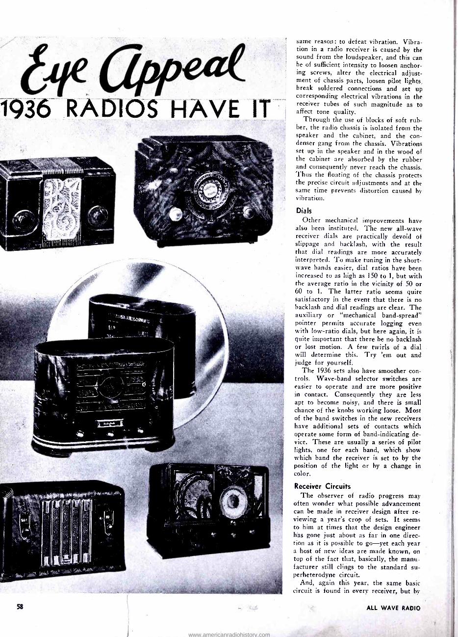
Eye Appeal? -Sure enough. Cast your eyes over the illustrations on this and the accompanying pages. The trend is "semi - modern," and this fits right in with the trend in the furniture field. The whole country has fallen for this design for the reason, we believe, that the semi -modern design expresses utility, and in doing so is necessarily simple and straightforward. Lines are clean, but not harsh, as they were in the earlier "modern" designs. There are no doo -dads and no "ginger- bread" glued on to break lines and other- wise make the cabinet look like grand- ma's curio cabinet.
The odd thing about this "semi -mod- ern" is that there is nothing modern
www.americanradiohistory.com

Illustrations Courtesy of
RADIO RETAILING
about it. It's a reversion back to the Early American or Colonial, during which "period" furniture was made of
maple and mahogany, and was as straight- forward as could be. The New Eng- landers in particular had no use for the dowdy. When they made a table, the only idea they had in mind was that it
should have utility -and to hell with the carvings and scrolls that mean nothing to
begin with and only complicate the view. But the radio cabinet is not the only
thing -on the face of the cabinet there must be a dial, a loudspeaker opening and various control knobs. Here again, improvements have been made. Rather than attempt to hide dials, the manufac- turer has made them larger than ever
with the result that they are easier to
read and handle. Furthermore, instead of attemping to hide the speaker opening with trick wood carvings so that it would look like a solid, the speaker has been
given "breathing space." Here again.
utility has been given first consideration. And is cabinet appearance any the worse for this frank manner of design? Not by a long shot! If anything, we would say they are decidedly more pleasing to
look at, and certainly easier to live with.
The Chassis
In the meantime, what has happened to
the receiver chassis? In what manner does it out -shine the chassis of last year? Considering first the mechanics of chassis construction, you will find upon close ex-
amination that most manufacturers have gone in for "floating " -a term and a
manner of building borrowed from the auto manufacturer. Floating a radio chassis is as necessary as floating an au- tomobile engine -and it is done for the
www.americanradiohistory.com
1936 RADIOS HAVE IT
58
same reason : to defeat vibration. Vibra- tion in a radio receiver is caused by the sound from the loudspeaker, and this can be of sufficient intensity to loosen anchor- ing screws, alter the electrical adjust- ment of chassis parts, loosen pilot lights, break soldered connections and set up corresponding electrical vibrations in the receiver tubes of such magnitude as to affect tone quality.
Through the use of blocks of soft rub- ber, the radio chassis is isolated from the speaker and the cabinet, and the con- denser gang from the chassis. Vibrations set up in the speaker and in the wood of the cabinet are absorbed by the rubber and consequently never reach the chassis. Thus the floating of the chassis protects the precise circuit adjustments and at the same time prevents distortion caused by vibration.
Dials
Other mechanical improvements have also been instituted. The new all -wave receiver dials are practically devoid of slippage and backlash, with the result that dial readings are more accurately interpreted. To make tuning in the short- wave bands easier, dial ratios have been increased to as high as 150 to 1, but with the average ratio in the vicinity of 50 or 60 to 1. The latter ratio seems quite satisfactory in the event that there is no backlash and dial readings are clear. The auxiliary or "mechanical band -spread" pointer permits accurate logging even with low -ratio dials, but here again, it is quite important that there be no backlash or lost motion. A few twirls of a dial will determine this. Try 'em out and judge for yourself.
The 1936 sets also have smoother con- trols. Wave -band selector switches are easier to operate and are more positive in contact. Consequently they are less apt to become noisy, and there is small chance of the knobs working loose. Most of the band switches in the new receivers have additional sets of contacts which operate some form of band -indicating de- vice. These are usually a series of pilot lights, one for each band, which show which band the receiver is set to by the position of the light or by a change in color.
Receiver Circuits
The observer of radio progress may often wonder what possible advancement can be made in receiver design after re- viewing a year's crop of sets. It seems to him at times that the design engineer has gone just about as far in one direc- tion as it is possible to go-yet each year a host of new ideas are made known, on top of the fact that, basically, the manu- facturer still clings to the standard su- perheterodyne circuit.
And, again this year, the same basic circuit is found in every receiver, but hi
ALL WAVE RADIO
www.americanradiohistory.com

genius and plenty of hard work, the engineer has made it do new things and do the old things in a better way.
Take sensitivity and selectivity, which, though not complementary, go hand -in- hand in receiver design. Sensitivity has not been increased in the modern receiver so much by increases in inherent tube amplification, but by using better com- ponents and simplified circuit structure. To begin with, the engineer has tackled seriously the problem of circuit losses brought about by poor or inadequate in- sulation, by an absence of constant circuit precision, and by the absence of proper isolation between successive stages of am- plification. Straight losses have been re- duced by using better grades of insulation material in coils and condensers, and by
protecting each part from heat and mois- ture through the use of impregnating compounds. Losses brought on by
changes in circuit adjustments have been obviated by the use of air -dielectric con-
One of the 1936 General Electric metal -tube receivers, with the new cyl-
indrical dial scale.
densers, such as the "Permaliner" type used in all the new G. E. sets. Stages have been isolated by increasing the amount of shielding between components and through the use of resistance -capacity filters in each vital tube circuit. Since heat and moisture will alter the electrical values of condensers and coils, these components are not only treated with damp- proofing compounds, but so placed in the chassis that they are well removed from power and rectifier tubes, power transformers and resistors of high -cur- rent- carrying capacity, all of which pro- duce plenty of heat.
Central Tuning Units
Special consideration has been given to the input circuits of receivers, for it is at this point that the true sensitivity of a receiver is determined; if input -cir- cuit losses are high, weak signals are in- tirely lost.
Bosch has reduced the losses in these
NOVEMBER, 1935
circuits by completely redesigning the radio -frequency, mixer and oscillator coil- switching arrangement. The coils used in these stages are fastened directly to the contacts of the wave -band selec- tor switch, with the result that approxi- mately 104 soldered connections are dis- pensed with, and wire leads simply don't exist. The coils and the switching device form a self- contained unit completely iso- lated and insulated from the receiver chassis. This "chassis- within -a- chassis" is mounted on rubber pads and, instead of there being a number of individual "ground" or chassis connections which can contribute to noisy operation, there is but one, and this is a flat, braided lead which completes the circuit between the central tuning unit and the main chassis.
Both G. E. and RCA have followed parallel lines in the design of the input stages -G. E. with the "Sentry Box" and RCA with the "Magic Brain." The basic ideas behind these units are the same as in the Bosch "Centr -O- Matic" unit; in each instance sensitivity is boosted where it should be boosted, by cutting losses to the limit.
Selectivity has been increased in much the same way -by a reduction in circuit losses, and by the use of at least one stage of tuned radio- frequency amplification in front of the mixer tube, usable on all wavebands. For real DX reception, and the absence of station and image inter- ference, an r -f stage on all bands is an absolute necessity.
Selectivity has also been increased in the intermediate -frequency amplifier stages by using transformers having high -Q coils and, in some instances (Fada, and Stromberg as examples) by the use of triple -tuned i -f transformers. In a few instances the Q of the coils has been increased by employing trans -
for,7ners having iron rather than air cores.
Automatic Volume Control All modern receivers, except some of
the midgets, have automatic volume con- trol. The action and effectiveness of this system has been increased in the new sets, and in most instances is so arranged that the amount or extent of the control action is correctly proportioned for each waveband. In the better receivers this control action has been divorced from the second detector so that one function cannot have an effect on the other. Either a separate tube is used, or the diodes of one tube are used separately.
Amplified automatic volume control is used in many receivers so that the con- trol action will be equally as effective on weak signals as on strong ones. This is highly important in connection with reception in the short -wave bands where extreme fading is the rule rather than the exception.
IPM Variable -selectivity control system in a
Zenith receiver. Selectivity may be adjusted for "DX" or "High Fidelity."
Acoustic Clarifiers used in Philco re- ceivers. These are not loudspeakers, but resonant cones, which eliminate
cabinet resonance.
L- A high -fidelity loudspeaker. This is used in conjunction with the Acoustic
Clarifiers, shown above.
Exterior and interior details of a "Per - maliner" (G.E.) This is an air- dielec- tric trimmer condenser. Advantages:
Lower losses. holds adjustment.
59
www.americanradiohistory.com

Even the CHASSIS are Different
High Fidelity
High fidelity and selectivity simply do not mix. Selectivity is required for DX reception, but the amount of selectivity required to permit inter -station inter- ference defeats tone quality.
In order that all -wave receivers can provide both distant reception without interference, and high -fidelity reception of local broadcast stations when desired, the design engineers have provided the more expensive receivers with "variable - selectivity" i -f amplifiers. The i -f am- plifier resonance curve or "band" is con- tracted to provide maximum selectivity for DX reception, and opened up or ex- panded for high -fidelity reception. When expanded, the full audio response of the broadcast station is permitted to pass th rough.
Zenith and St romherg-Carlson use continuously variable I -F Expanders so that any degree of selectivity may be had. Atwater Kent uses a system con- trolled by a two- position switch, provid- ing maximum and minimum selectivity. G.E. has one model receiver in which the entire i -f amplifier is cut out of cir- cuit when high- fidelity reception is de- sired. In this instance the r -f amplifier feeds directly into the detector. Howard uses separate i -f amplifiers for high -fi- delity and DX and the tone response is further enhanced through the use of sep- arate audio amplifiers for high and low f requencies.
Audio Amplifiers
There is quite a hit of variety in the audio- frequency amplifiers of modern re- ceivers. Of course, in the smaller receiv- ers using hut a single output tube, the pentode is still universally used. But you never can tell what you are going to run into in sets having more than one power tube.
Wells Gardner and Stewart -Warner incline toward the 2A3 Class AB triodes in their larger sets. On the other hand, Stromberg has turned from the 2A3 to the type 42 pentode, but uses the 42's connected as triodes in a Class A Prime circuit. G.E. uses the 6F6 pentodes, as do many of the other manufacturers. In practically every case, however, the pent- odes are used in Class AB or A Prime circuits -Class A is practically out of the picture. It is interesting to note, however, that the Zenith "Stratosphere" receiver ($750, if you're interested) uses two type 42's as drivers for eight type 45's in the output! The 45 is still a good tube, and don't you forget it.
ALL WAVE RADIO
www.americanradiohistory.com

Power output is what the manufac- turer wants to say it is. Mentioning power outputs -at least undistorted power outputs -is as foolish as stating the frequency response of a receiver. Obviously, modern receivers have suffici- ent audio output to suit most people, and have good tone to boot. But in most cases the statements with regard to out- put and frequency response should be
taken with a grain of salt. It's a harm- less pastime with some manufacturers and is no doubt related to the same mo- tive that impels an auto manufacturer to go over -optimistic on the number of miles per gallon you can get out of his
cars.
Metal, or Glass, or What?
And now for that burning question. Are the metal tubes better than the glass babies? It's a burning question, all right, and not so easy to answer. But, first, let's see who's using what.
The following manufacturers are using a partial complement of metal tubes in
the hulk of their receiver models: Air King, Atwater Kent, Automatic Radio, Capehart, Case, Crosley, Detrola, Emer- son, Fada, Garod, General Electric (complete line, all metal), Grunow, Gil - fillan, Halson, Howard, International "Kadette" (optional), Midwest (op- tional), Arvin, Pierce Airo, Pilot, RCA Victor, Remler, Sentinel, Sparton, Stew- art- Warner, Stromberg- Carlson, Bosch, Wells G a r d n e r, Westinghouse and Zenith.
Quite a list. Nov let's see who isn't using them : Ansley, Autocrat, Fairbanks - Morse, Freed, Galvin, H ammarlund, Lincoln. L'Tatro, Silver, Patterson, Philco and Scott.
Not quite so many in this list, but no reflection on the manufacturers.
Who uses the glass -metal tubes? -that is, the glass tubes with the octal bases? Belmont for one, and with these tubes optional in the International and Mid - west receivers.
Will more of the manufacturers take up with the glass -metal tubes? We don't think so. The glass -metal tube is a stop- gap. It was brought out principally to fill in for metal tubes in receivers already produced with the octal -type sockets. Now that tube manufacturers are catch- ing up on production, it is doubtful if
the metal -tube shortage will last much longer. As soon as plenty of metal tubes are available, the owner of a set using the glass -metal type can switch over if he wishes. But, since the glass - metal tube has no advantage over the standard glass tube, there is hardly any reason for its continuance and less reason for more manufacturers to take up with it.
The question therefore boils down to the point as to whether set manufacturers sticking to the glass tubes will turn to the
NOVEMBER, 1935
"All - Wave Radio
Magazine" - Flashed
to New Yorkers from the top of a hotel on
Broadway, during the National Electrical & Radio Exposition. The sign was projected on
a huge screen, and
drew much attention.
metal after the shortage has been taken care of. We believe they will -when, as and if they are satisfied that the metal tube actually has advantages over the
glass type. Philco has come out openly
and stated that the glass tubes are su-
perior. G.E. and RCA Radiotron are re-
sponsible for bringing out the metal tubes, and Philco is responsible for cast- ing suspicion upon them. And, since none
of these companies are to he taken lightly, you want to know who's right.
It is too early to provide a definite
answer, but this much may he said: Most of the hugs in metal tubes were due to
production difficulties which have since
been pretty well ironed out. The 5Z4 rectifier was admittedly poor, but we
have been advised that this tube has been
redesigned. In the meantime, manufac- turers have been using the 5Z3 glass rec-
tifier in the metal -tube receivers -and if
they should continue to do so until dooms-
day, it would be no reflection on the reg-
ular line of metal tubes. It makes little difference what type of rectifier is used,
as the advantages of metal construction are more apt to be apparent in the re-
ceiver tubes where improved shielding, sturdier construction and lower capacity between elements really means something. Nevertheless, we wouldn't he surprised if the new 5Z4 turned out to be a su-
perior power rectifier anyhow -but glass
or metal, the rectifier tube used in the
power supply has only to provide suffici-
ent voltage and current, with good regu-
lation ... the real work is done by the
receiver tubes.
Such tests as we have been able to
conduct seem to indicate that the metal tube has a slight edge on the glass tube in the short -wave bands. Both types ap- pear about equal in the broadcast band. It has been our experience that a metal - tube receiver is quieter in operation, a
point which has been mentioned in their favor, but not wholly accepted on the face of the assertion.
In comparing metal- and glass -tube re- ceivers, it is unfair to pass judgment on
the basis of the number of tubes. Re- member that in glass -tube receivers a
single multi- purpose tube serves as sec- ond detector, automatic volume control and audio- frequency voltage amplifier, whereas in the metal -tube receiver the diode detector and automatic volume control is a separate tube. Therefore, a
metal -tube receiver has, through neces- sity, one more tube than an equivalent glass -tube receiver.
The present types of metal tubes were purposely made to have characteristics approximately the same as the glass types they replace. Therefore it is unreason- able to expect that the metal tubes should
provide far superior results. The point
is, it has been demonstrated that the
new structural design made possible
through the use of metals will yield im-
proved operation in spite of the similarity in characteristics between the glass and
metal types. Upon this new structure will be based the tubes of the future - tubes having characteristics unattainable in glass types.
61
www.americanradiohistory.com

WHAT A DIFFERENCE in receivers now aN compared with those of the days when we labored to tune in VRY, British Guiana; NRH, Costa Rica; HKA and HKC, Columbia; HRB, Honduras; G5SW, England; F3CID, Indo- China; X26A, Mexico; YVI I B1VIO, Venezuela ;
CMCI, Cuba. While these stations, now deleted, have
pleasant memories for those who have followed the hobby of I)X for some years, other stations have taken their places, and today the advance of short- wave radio finds powerful broadcasting plants in nearly every land transmitting programs of value into our homes, and being received and enjoyed by us through modern all -wave receivers operated from the house line instead of batteries, etc.
'All- Waving" Today it is about impossible to buy a
broadcast set. All manufacturers are building all -wave receivers. Whether some owners of these all -wave receivers do not appreciate the ability of their receivers to bring in distant programs, or are not inclined to find out whether they can or not but simply are content to hear only the local stations, are questions to be answered by the individual alone - but those who follow the DX pastime think that a great many are missing many enjoyable hours by not getting away from their own local stations.
You may, therefore, if you wish sit in your own comfortable chair with your all -wave receiver and listen to consistent reception from every corner of the earth -from stations to the south of us with
their programs of rhythmic native music, fascinating rhumbas, paso dobles or tangoes, which breathe the very spirit of South America, or you may tune in far- away Japan, the "Land of the Rising Sun," where the music and song cannot be mistaken for anything but Japanese. You may listen to the superb programs of England, Holland, Portugal, Ger- many and France, the marevllous oper-
Mr. Hinds received the signals more readily than the Vertification Card . .. it is addressed to "Monkess" in- stead of Yonkers.
CONDUCTED BY
J.B.L.H I N DS
tion daily from all countries in the world, for there are many conditions to be taken into consideration which make that impossible ; but those conditions are being rapidly overcome. With improved re- ceivers and antenna systems and the won- derful advance in broadcasting equip- ment, in a short space of time we have seen such a marked improvement that nothing seems impossible.
den
LUFTSCHIFFBAU ZEPPELIN O. M. B. N.
Fernsprecher S. A. Nr. eel und 851 TelepremmAdreese: LUFTSGIFFOAU
Giro-Konto bel der RelchebenkNebenstelle FNedrI hehe /en
Goetsched -Konto STUTTGART Nr. 7814
FrIsdrI¢hshafsn s. B..
October 2nd 19 34
Postkarte
Mr.
J.B.L. $ i n d 9
85th Str.Andrews Pl.
Monkess N.Y. USA
atic renditions and music from Italy, keep abreast of the times through the League of Nations stations at Geneva, Switzerland, or twirl the dials and bring the carriers of far -away India, Aus- tralia, China, the Fiji Islands, the many transmitters in the Dutch East Indies, or from the heart of Africa.
I will not make the claim however, that you will receive consistent recep-
62
Mr. Hinds in his receiving room, at
Yonkers, N. Y.
Station Lists In revising and compiling the station
lists for this issue it will be noted that I have combined the Star Short Wave Broadcasters and Phone and Experi- mental stations and shown all stations on the air in order by frequency, which I believe will be a beneficial change and materially assist those receiving signals to locate a station more readily. As a great many still calibrate their receivers by wavelength in meters, I am showing the meters for each station in addition to the kilocycles. The information in these tables was carefully prepared and contains only such transmitters that are known to be on the air, being compiled from records of actual contact, operating companies and other reliable available sources.
If one, however, refers to the latest issue of "World Short -Wave Radio- phone Transmitters," compiled and is- sued by the Department of Commerce through the Bureau of Foreign and Do- mestic Commerce, there will be noted various frequencies assigned which are
ALL WAVE RADIO
www.americanradiohistory.com
not listed in the tables referred to, either due to the fact that they never have been contacted or they are assigned, but not used, frequencies. One should bear in mind that frequencies reported in
tables as used. at certain periods of the day or night may, of course, be used at other periods than those named.
Many stations such as the Java trans- mitters, PLE, PMA, PMN, PLP, Italian IRW, IRM, IRG, etc., are classed as phone and are used often in
relaying and transmitting programs, as
likewise with many classed as experi- mental stations.
Items of Interest
The popular station EHQ, at Madrid, Spain, is being heard as late as 9:30 P. M.
of late, though their schedule for Oc- tober just received does not show them on the air after 7:30 P. M. at the closing of the International Broadcasting Com- pany's added attraction of EHQ's fine
regular program. ZBW, Hong Kong, China, is coming
in quite regularly on 8750 KC or 34.29
meters. Time on the air and address of
station are shown in this issue. Their verification card also shows them work- ing on 5410 KC or 55.46 meters, although no reports of reception have been re- ceived on the latter frequency.
Information has been received that COC, Havana, Cuba, has been changed to call COCO, and COH, Havana, Cuba, to COCH.
World -Wide Broadcasting Corpora- tion station WIZAL, Boston, advise they will broadcast every Tuesday, Thursday, and Sunday evenings starting October 1st, using 11790 and 6040 KC; power 10,-
000 watts. They do not say if each pro- gram is to be broadcast simultaneously on both frequencies or not, so the same time for each frequency is shown in the tables.
Germany is furnishing verifications for DFC, DFL and other special transmit - ters, but state they prefer to receive short -wave reports of programs from DJA -B -C -D and E.
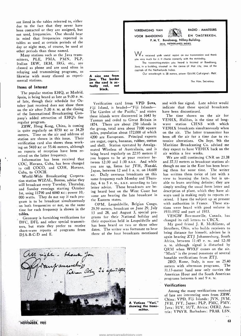
A nice one from lava. The border on the card is ac- tually red, not
black.
VEREENIGING VAN
VOOR BANDOENG
RADIO - AMATEURS
EN OMSTREKEN.
P. M. Y. Bandoeng, Nillmy- Building. JAVA, NETHERLANDS INDIES.
We received your useful report on our transmission and thank
you very much for it. It checks correctly with the stationlog.
The transmitting -station you heard is located at Bandoeng,
Java, in a building, situated in the centre of that city, one of the
capitals of the Netherlands Indies.
Our wavelength is 58 meters, power 0,6 kW. Call- signal : PMY.
The Hon. Secretary.
Verification card from VPD Suva, Fiji Island, is headed -"Fiji Islands - The Garden of the Pacific," and states these islands were discovered in 1643 by
Tasman and ceded to Great Britain in
1874. There are about 250 islands in
the group, total area about 7100 square miles, population about 172,000 of which 4200 are Europeans. Principal exports are sugar, copra, bananas, rubber, cotton and shell. Station operated by Amalga- mated Wireless of Australasia, and is
being heard regularly on 22.95 meters if
you happen to be at your receiver be-
tween 12:30 and 1:30 E.S.T. And while you are up, listen for JVH, Nazaki, Japan, between 12 and 1 A. M. on 14,600
KC. Daily overseas broadcasts on this same frequency each Monday and Thurs- day, 4 to 5 P. M., E.S.T. according to late letter advice. These broadcasts are be-
ing heard best on the West Coast but some are hearing the late broadcast in
the Eastern states. OPM, Leopoldville, Belgian Congo,
29.59 meters, broadcast on June 29, July 13 and 28, and August 3, special pro- grams for their National holiday and their exposition held in Leopoldville and has been heard on two or three other dates. The writer was fortunate to hear three of the four broadcasts mentioned
NOVEMBER, 1935
A Vatican "Veri," showing the trans-
mitter.
and with fine signal. Late advice would indicate that these special broadcasts have been discontinued.
The time shown on the air for VE9HX, Halifax, is the time of long - wave station CHNS with which VE9HX broadcasts simultaneously when on the air. The latter transmitter has been off the air for a time due to ex- tensive alterations. On Sept. 9th the Maritime Broadcasting Co. advised me they expect to have VE9HX back on the air within a few weeks.
We are still continuing CNR on 23.38 and 37.33 meters as broadcast stations al- though no one in the East has been hear- ing them for some time. The writer has written them twice of late with a view to learning the facts, but is un- able to learn anything definite ; they are simply sending the usual form letter and description of plant, which they have al- ways used in making reply to reports re- ceived. I have the subject up at present with authorities in France. These sta- tions were heard with good volume in
1931 -1932 and part of 1933. VE9GW Bowmanville, Canada, has
changed its call letters to CRCX. My good friend J. R. McAllister, of
Struthers, Ohio, who builds receivers to bring distance for himself, advises he is
again hearing ZTJ Johannesburg, South Africa, between 11:45 P. M. and 12:30 A. M. although signal is disturbed by
QRM when W9XF comes on the air. "Mack" is the proud possessor of several bonafide verifications from ZTJ.
2R0, Rome, Italy, is now on 25.40 meters with afternoon programs. The 31.13 -meter band now only carries the American Hour and the South American programs between 6 and 9 P. M.
Verifications Among the many verifications received
of late are interesting ones from ZBW, China; VPD, Fiji Islands; JVN, JVM, JVH, JVT, Japan; PLP, PMC, PMY, Java; SUV, SUT, Africa; OER2, Aus- tria; VP6YB, Barbadoes; PRA8, LSN,
63
www.americanradiohistory.com

CEC, HJSABE, South America; TIR, "I'IU, TIRCC, TIPG, Central Ameri- ca; HA'1'4, CSL, CTIGO, and DGN. Europe; and COCD, CO9WR and CO9JB, Cuba.
An excellent method to preserve your verifications is to place them in scrap books with "Art Corners" so they, may he removed and replaced at any time. I
have recently cared for mine in this man- ner in well bound inexpensive books, as- signing them in alphabetical order by countries and reserving space by blank sheets between countries. These books come in loose -leaf form and no trouble is therefore experienced in laying them out. An index can be used showing book number, countries assigned to each book, etc., as desired. The different series of postage stamps of each country as taken from the envelopes containing the veri- fications are posted on the respective page in the hook.
New Stations Listed
CO9JQ, Cuba, 8665 Kc; ZP10, Para- guay, 8110 Kc; CO9WR, Cuba, 11,800 KC; CEC, Chile, 10,670 Kc; VPMR, British Givana, 7080 KC; YV8RB, and YVIORCS, Venzuela, 5880 and 5720 Kc respectively; IRG, Eritrea, 14,710 ice, and HB9B, Switzerland, 7118 and 3770 KC,
TFJ, Reykjavik, Iceland, on 12,240 KC, is being heard quite often of late; usually in the morning, testing with Eng- land. Letter advice from them states they are usually on the above frequency and transmit occasional musical and other broadcast items and that their transmitter pumps 7/ KW into the aerial and works on a directional aerial towards the East. Their other transmitter is also now testing on 9060 KC. No regular broadcast hours yet assigned.
New Stations Not Listed New stations reported or heard are as
follows: IRJ, Rome, Italy, 14,730 Kc, Phone, heard around 6:00 A. M. HJ2ABD, Bucaramanga, Columbia 9570
KC, evenings. PZH, Paramaibo, Suri-
Have you one of these? If you don't know when to lis- ten for Japan, ask
Mr. Hinds.
POST CARD KOKUSAIDEN WA KAISHA LTD.,
Osaka aldg, Kojlmacblku, Tokyo, Japan.
Tokyo,Oet. - 1934 .. Dear Sir,
Thank you fot your kindness of in. forming, us.your receiving results of JVM on July_ let,. 1934
We are very much obliged to you, if you will kindly let us know your receiv. ing ccndition of our. titatlon in the future,
Yours Sincerely,
Kokusai Denwe Kaisha, Ltd., (International Wireless Telephone
Company of Japan, Ltd.)
per 1 S.Kuramochi
Mr. J.B.I. Hinds 85 St., Andrews Place, Yonkers, New York, U.S.A.
nam, Dutch Guiana, 7140 Kc, said to be broadcasting daily until 5 P. M. and 6:40 to 9 P. m. on Mondays and Thursdays. Also a new Mexican with reported call .13J B on about 11,600 KC. The writer heard them testing shortly after mid- night on Sept. 15th, with fairly good sig- nal-am requesting that reports be for - warded to P. O. Box 2825 Mexico City. IQA, Rome 14,735 KC, has been heard irregularly of late with musical programs 11 P. M. to midnight. Also reported on voice on other frequencies.
Relay stations VK5WB, Port Ade- laide, South Australia, said to be broad- casting experimental broadcasts each Sunday morning between 2 and 3 A. M., E.S.T. 7310 KC. Kookaburra opens each transmission. It is reported that five transmitters have been ordered from Marconi works for Afghanistan to be in- stalled at Kubal, Maimana, Khanabad, Krost and Dujazunga. Kubal transmit- ter to cover a range of from 15 to 80 meters; output 3/ to 4/ KW and to communicate with Moscow, Tokio, Shanghai, Rio de Janeiro, Capetown and Melbourne. The other transmitters for internal communication and 250 watts each.
The rebroadcast of speech of Emperor Haile Selassie over the NBC network on Friday Sept. 13th was an exceptionally good rebroadcast. The Short -Wave Re-
dated
log.
BANDOENG, August 21th,1934.
Dear Mr Hinda,
Your report on station p L íl , 9420 kcjsec, June 28th, 19311.. checks correctly with the station
» K
Thank you.
V DER VEEN, Engineer -In- charge,
Java Wireless Stations. Bandoeng, Jere.
64
Another "V e r i" from Java . as valuable to the owner as a rare
stamp.
porter (2RC) Hendersonville, N. C., re- ports direct reception of the s.w. station in Addis Ababa, Ethiopia, transmitting the broadcast mentioned on 18,270 Kc and a later broadcast on same date at night. Call letters ETA. The writer heard the rebroadcast but was not fortu- nate in contacting either frequency on that date. It is said more broadcasts will follow.
A station is being heard and reported as HC2CW, Ondas de Pacifico, Guaya- guil, Ecuador, on about 840 Kc or 35.69 meters. Some believe it is the same sta- tion as HC2AT which has been broad- casting on and around that wavelength, but which was reported by some as closed down, but by others as still being heard. The writer received advice from HC2AT a short time ago that they were shortly to increase their power but no mention of leaving the air. Schedule of HC2AT is therefore still reported in list.
On Wednesday and Saturday of each week between 5 and 7 P. M. E.S.T. a little S0 -watt station CT2AJ at Ponta Del - grada S. Mignel, Azore Islands, can be heard broadcasting programs on 4000 Kc or 75 meters. Tune to the high -frequency side or end of the 75 -meter phone band until you hear no more U. S. amateur phones and then slightly back off the dial. While I have not heard this station, others have a verification.
An official communication from the Swiss Short -Wave Association (USKA) of Bern, Switzerland, announce that short -wave broadcasts are to be radiated the first Monday of each month from several Swiss stations. These programs have been arranged for Oct. 7th, Nov. 4th, Dec. 2nd, Jan. 6th, and Feb. 3rd. Will be broadcast 3:10 to 4:15 P. i<t. E.S.T. over HB9B, 14,236 Kc, with a beam aerial to North America; HB9H, 7005 KC, with uni- directional aerial for Europe, Australia, North and Central Africa, and HB9J, 14,400 Kc, to South and Central America. In order to se- cure a world -wide coverage program will be repeated on same days from 6 to 7
(Turn to page 96)
ALL WAVE RADIO
www.americanradiohistory.com

A receiver designed to "step out" -not to provide the best quality and high power output. Compact, completely shielded, no frills - a
Greyhound of the Air.
FIG. 3
The Lafayette A WELL -KNOWN engineer recently pur- chased a console receiver costing over $200, for the express purpose of using it
for listening in on the short -wave bands. He selected a good receiver, and it must he said in all fairness to the manufac- turer, that it worked exceedingly well. However, after using the receiver for some time, this engineer was frank enough to admit that, since he wished a
receiver for the short -wave bands only, he could have saved himself quite a bit of money and in the bargain obtained a re- ceiver designed principally for this one class of service, had he given thought to the numerous sets designed for amateur use.
What You Pay For
This is undoubtedly a point which has been given very little consideration by the man who is interested primarily in dis- tance reception on all the usual wave
Professional Nine By FRANK LESTER
WHOLESALE RADIO SERVICE, INC.
bands covered by an all -wave receiver, and only secondarily in what is usually referred to as "tone quality," but upon analysis turns out to mean the capability of a receiver to turn out more power than can be comfortably used in the home for any purpose other than the reproduction of symphony concerts and recorded mu- sic.
This is a very interesting point, in that it demonstrates what the manufacturer of any specific type of receiver does with his pennies. If, for example, we take $60 as a fair price for a table model all -wave receiver having a good sized dynamic speaker and a Class AB push pull output stage, it is apparent that a fair percent- age of the cost has gone into the cabinet for one thing, into the dynamic speaker
Fig. 2. The Lafayette Professional Nine. Speaker at left, dial at right, controls below -well balanced throughout.
NOVEMBER, 1935
for another, and also into the power out- put stage. Now, if "living -room beauty" is of no consequence, fine tone quality of only passing interest, excessive power out- put of no regular value, but distant re- ception qualities the prime requirement, it is obvious that if some of the $60 tied up in the cabinet, the speaker and the power stage, were used instead to provide increased sensitivity and selectiv- ity, the DX man would get more for his money.
Professional Receiver
Undoubtedly there are any number of people who wish to have the features of high sensitivity and selectivity in an all - wave receiver without having to pay an excessive price for it. That is why there is presented here the circuit and constructional details of a moderate priced professional receiver, designed specifically for amateur use, which may be purchased complete or in kit form. The reader will appreciate as we progress with the description of this receiver that it contains features of importance to the DX listener not to be found in the gen- eral type of all -wave receiver for home use.
The Circuit The complete schematic diagram of the
Lafayette Professional Nine is shown in Fig. 1. Starting from the upper left of the diagram it will be noted first of all that there are four wave -band positions and that separate sets of coils are used for each hand. The coverage is continu- ous from 9.7 to 560 meters.
There is a stage of tuned- radio -fre- quency amplification which functions on all four bands. This stage, using a type 6D6 tube, is transformer coupled to a
6C6 type tube which is used only as the first detector or mixer. A type 41 pen- tode, connected to function as a triode, is used as the high -frequency oscillator.
65
www.americanradiohistory.com

Due to the high transconductance of this tube it has a high degree of stability on the shortest wavelengths where many other types of tube fail to function satis- factorily as high-f requency oscillators.
The output of the 6C6 first detector is fed into the first intermediate -f re- quency amplifier stage, which uses a 6D6 tube. There is a second i -f stage in which is employed the pentode section of the 6B7 tube. The plate circuit of this tube feeds into the primary winding of the third i -f transformer, and the secondary winding of this transformer feeds the diode plates of the 6B7 which are con- nected in parallel and provide both rec- tification of the signal and automatic vol- ume control.
There is included in this diode circuit a load resistor across which appears the direct- current component of the rectified signal. This voltage is used to provide automatic control bias on the 6D6 r -f tube and on the 6D6 i -f tube. I'he audio-f requency component also appears across the load resistor and this is fed through the volume - control potentiometer, the arm of which connects to the control grid of the 6C6 audio frequency voltage amplifier tube.
The 6C6 audio tube is resistance coupled to a type 42 pentode power tube. A phone jack is connected in the plate circuit of the 6C6 a -f tube so that head- phones may be used for weak -signal re- ception. When the phones are plugged into the jack the output of the 6C6 a -f tube is automatically disconnected from the power tube.
A variable -condenser type of tone con- trol is connected in the grid circuit of the type 42 pentode and proves very
R. F CO/LS
handy for reducing background noise and certain forms of inter -station interfer- ence.
The type 42 pentode feeds a dynamic speaker the field coil of which is used as
the filter choke in the power supply unit which employs a type 80 tube.
It will be noted in the lower part of
the diagram that there is a type 76 tube used as a beat -frequency oscillator. This oscillator not only permits the reception of cw code signals but is also valuable as a broadcast -station finder. It will in- dicate the presence of a modulated or unmodulated carrier by a high -pitched sound when the dial pointer is passed through a station.
Special Control Switch
Now take note of the tandem switch shown in the diagram just below the 6C6 first detector tube. Section A of this switch cuts in and out the automatic vol- ume control action. When the arm of this section is on Point 1, automatic bias control is placed on the r -f and i -f tubes. When the arm of this section is on either Point 2 or 3, the grid- return circuits of these two tubes are grounded as they would normally be with no automatic volume control circuit.
Section B of the switch is inoperative until it reaches Point 3 when it places high voltage on the plate of the beat - f requency oscillator and so places it into operation.
Section C of the switch connects the cathodes of the r -f and i -f tubes to ground when automatic volume control is being used, so that both of these tubes will be
supplied with residual bias, developed in each case by a 350 -ohm resistor. With
DETECTOR CV/LS jH/EL D
Section C on either Point 2 or 3, the cathodes of the r -f and i -f tubes are con- nected to ground through a 5000 -ohm potentiometer which serves as a manual sensitivity control by varying the bias on these tubes.
Reviewing the function of this tandem switch, composed of Sections A, B and C, it will be seen that with the switch arms on Points 1, automatic bias control is
placed on the r -f and i -f tubes and the cathodes of these tubes connected to ground. With the arms on Points 2 the automatic volume control action is cut out and the sensitivity or gain control is
thrown into circuit so that the operator may adjust the gain or volume of the receiver manually. With the arms of the switch on Points 3 the sensitivity of the receiver is still controlled by the manual gain or volume control and, in addition, the beat -frequency oscillator is brought into play. Since automatic volume con- trol cannot be effectively used when re- ceiving cw signals, no provision is made to have it thrown into circuit when the beat -frequency oscillator is on.
A front view of the receiver is shown is Fig 2. The controls from left to right are: On -off switch; tone control; stand- by switch, which cuts off the "B" sup- ply; volume control; automatic volume control and beat-f requency oscillator switch ; tuning control, which operates the double pointers on the airplane dial; the sensitivity or gain control; and, lastly, the four -position wave -band switch.
A view of the chassis is shown in Fig. 3. This is so constructed that if it is
found desirable, the left -hand unit con- taining the speaker, the power amplifier and the power- supply unit, may be taken
IDL LIME CONTROL
= i 20o, IR P S
.'J*' LP. S P
I F F
200V
OOV.
20M- %¢w_
.002
/ 350 - 200V.I XeW
/000 /.! W. 200M
%4L N/-
I 4-R .ODOS V A R Ñ R B L E I__ dao J-B .0013 2C .00/3 . 0.001 FIXED' _,/
2-D2-.004J MOLDED ALL ARRAL¡¡,,EL PADS SfMM/ó. VRR/ABLE I
AL:L RESISTORS JOD GATT UNLESS I. A, OTHERWISE NOTED. ,
I IR FREQUENCY LD70KC. i{I poSITION ON CONTROL Sw/TCN no ONLY , -.- i2 . .r .. CATHODE CONiQOL . /iUlBERTLÖC -.._._ .-. 002-
RF. CNOX£
ee 2
200V
550 yDw
500M
y¡W
Of
owV.
TONE CONTROL
OSCILLATOR COILS
.oó005
200M pf,/w. 5M 2w
005 - 600V.
c4PERKE2 FIELD
76 SSO
/W
*0v..
.S
T SM /w / N'
ecbT OSC/LLATOR
CAW Mt FOR LEAD WIRES TO If, á BERFEREQ. COILS I BorrON vitw of ALL HORC.
GREEN®GR /D BLUE = PL ßTE SOCKETS UMW ABOVE. BLRCK.. GRID RETLRN RED= Bt I _ J
Fig. 1. The schematic diagram of the Lafayette
BMW. án/e 40ou uooV
/OM/N 35V
.SweowER
Professional Nine. See text for explanation of tube and circuit functions.
NOVEMBER, 1935 67
www.americanradiohistory.com
1L5
.. ®: 71.1e1 !6,4re; II.NCi 11.6MC i_..- .
out of the cabinet and mounted some dis- tance away rrom the receiver proper.
Assembly Procedure
It will be noticed that the chassis is supplied in three separate parts, one part of the chassis incorporating the power supply and output audio stage, and the other part the tuning condenser and dial, along with all of the intermediate fre- quency stages, and last, the completely assembled, wired and tracked coil switch.. ing arrangement. Each of the coil switch- ing arrangements have been carefully tested. It is therefore absolutely impera- tive that none of the trimmer adjust- ments are varied, unless one wants to he extremely critical, and after the receiver has been completely wired, make some slight adjustments of the parallel trim- mers. Needless to say this procedure should not be attempted unless a cali- brated oscillator is available that will cover the wavelength range of this re- ceiver. Great care has been taken in
properly tracking and aligning this coil switching unit, and it has been found that if the picture wiring diagram is
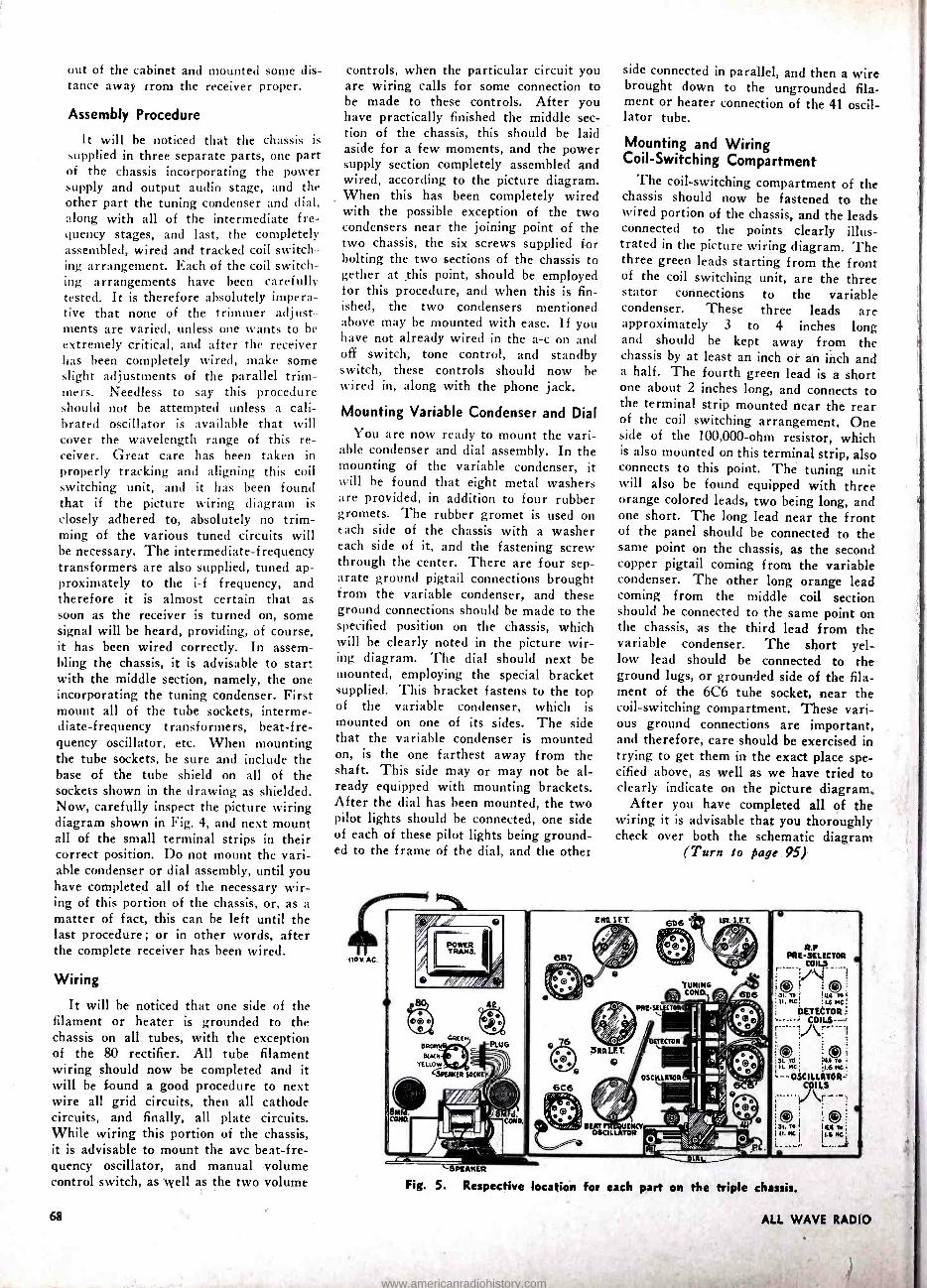
closely adhered to, absolutely no trim- ming of the various tuned circuits will be necessary. The intermediate- frequency transformers are also supplied, tuned ap- proximately to the i -f frequency, and therefore it is almost certain that as soon as the receiver is turned on, some signal will be heard, providing, of course, it has been wired correctly. In assem- bling the chassis, it is advisable to start with the middle section, namely, the one incorporating the tuning condenser. First mount all of the tube sockets, interme- diate- frequency transformers, heat -fre- quency oscillator, etc. When mounting the tube sockets, he sure and include the hase of the tube shield on all of the sockets shown in the drawing as shielded. Now, carefully inspect the picture wiring diagram shown in Fig. 4, and next mount all of the small terminal strips in their correct position. Do not mount the vari- able condenser or dial assembly, until you have completed all of the necessary wir- ing of this portion of the chassis, or, as a matter of fact, this can be left until the last procedure; or in other words, after the complete receiver has been wired.
Wiring
It will he noticed that one side of the filament or heater is grounded to the chassis on all tubes, with the exception of the 80 rectifier. All tube filament wiring should now be completed and it will be found a good procedure to next wire all grid circuits, then all cathode circuits, and finally, all plate circuits. While wiring this portion of the chassis, it is advisable to mount the avc beat -fre- quency oscillator, and manual volume control switch, as well as the two volume
controls, when the particular circuit you are wiring calls for some connection to be made to these controls. After you have practically finished the middle sec- tion of the chassis, this should be laid aside for a few moments, and the power supply section completely assembled and wired, according to the picture diagram. When this has been completely wired with the possible exception of the two condensers near the joining point of the two chassis, the six screws supplied for bolting the two sections of the chassis to gether at this point, should be employed for this procedure, and when this is fin- ished, the two condensers mentioned above may be mounted with ease. If you have not already wired in the a -c on and off switch, tone control, and standby switch, these controls should now be wired in, along with the phone jack.
Mounting Variable Condenser and Dial
You are now ready to mount the vari- able condenser and dial assembly. In the mounting of the variable condenser, it will he found that eight metal washers are provided, in addition to four rubber gromets. The rubber gromet is used on e ach side of the chassis with a washer each side of it, and the fastening screw through the center. There are four sep- arate ground pigtail connections brought from the variable condenser, and these ground connections should be made to the specified position on the chassis, which will be clearly noted in the picture wir- ing diagram. The dial should next be mounted, employing the special bracket supplied. This bracket fastens to the top of the variable condenser, which is mounted on one of its sides. The side that the variable condenser is mounted on, is the one farthest away from the shaft. This side may or may not be al- ready equipped with mounting brackets. After the dial has been mounted, the two pilot lights should he connected, one side of each of these pilot lights being ground- ed to the frame of the dial, and the other
side connected in parallel, and then a wire brought down to the ungrounded fila- ment or heater connection of the 41 oscil- lator tube.
Mounting and Wiring Coil- Switching Compartment
The coil- switching compartment of the chassis should now be fastened to the wired portion of the chassis, and the leads connected to the points clearly illus- trated in the picture wiring diagram. The three green leads starting from the front of the coil switching unit, are the three stator connections to the variable condenser. These three leads are approximately 3 to 4 inches long and should he kept away from the chassis by at least an inch or an inch and a half. The fourth green lead is a short one about 2 inches long, and connects to the terminal strip mounted near the rear of the coil switching arrangement. One side of the 100,000 -ohm resistor, which is also mounted on this terminal strip, also connects to this point. The tuning unit will also be found equipped with three orange colored leads, two being long, and one short. The long lead near the front of the panel should be connected to the same point on the chassis, as the second copper pigtail coming from the variable condenser. The other long orange lead coming from the middle coil section should be connected to the same point on the chassis, as the third lead from the variable condenser. The short yel- low lead should be connected to the ground lugs, or grounded side of the fila- ment of the 6C6 tube socket, near the coil- switching compartment. These vari- ous ground connections are important, and therefore, care should be exercised in trying to get them in the exact place spe- cified above, as well as we have tried to clearly indicate on the picture diagram.
After you have completed all of the wiring it is advisable that you thoroughly check over both the schematic diagram
(Turn to page 95)
en' LET. 6D6 16T. RT.
6aT
4
R.' PRE-SELECTOR
-
O 10 al. To ka ,o 11. He! :t.6MC
DETECTOR
o :3L Ñ ; YN ro . `II. MC .46 MC;
- OSCILLATOR=
cña
Fig. 5. Respective location for each part on the triple chassis.
68 ALL WAVE RADIO
www.americanradiohistory.com
A BOUQUET OF Tube Roses to that dra- matizer of radio technicalities, John Mills, who has created for lovers of mu- sic the entertaining book "A Fugue in
Cycles and Bels," which tells what elec- tricity is doing for music -and to the publishers of the book, our warmest re- gards for having tickled us no end with the spicy bit of information, framed in
their own words, that "the location of
one's seat makes a great difference in the music of a violin solo."
"GIVE BEAT NOTE a shot of corn juice; Ire's good now, but ..." ( From a letter by Z. A. Ridgeway, San Diego, Calif.)
Never had I left that trophy room without turning my head just a wee bit to catch a last, guarded view of the Ben- gal Tiger.
Though I had slain her with my own hands, the impression had always re- mained with me that there was life in
the old cat yet. Stuffed as she was, the one good eye she had left would glare and glitter at the most unexpected mo- ments. Yet the vacant socket through which I had once plunged my dagger to the hilt, bore mute (or would one say blank) testimony that the she -devil was as dead as a blown bottle.
It was with no great surprise, then, that one night about half after one, as I
felt my way into this darkened chamber, there came to my ears the low, fearsome hiss of the Jungle Cat ready to make its kill -and with no more surprise that I
saw cutting through the death -like black- ness of that chamber the evil, green gleam of that one, good eye.
My days in Africa taught me never to retreat before the Cat of Cats. So, grip- ping the neck of the bottle -now com- pletely drained of corn -I slowly ad- vanced until, eye -to -eye with my antag- onist, I let loose with all I had . . .
I am told that I was found sprawled on the floor at the foot of my brand new RCA Victor Magic Eye radio; out like a
light. Out as well was the Magic Eye, its glass intimately mingled with the re- mains of what once had been a bottle of
good cheer.
HAVING, FOCUSED your attention on the Magic Eye, permit us to make lip noises at the engineers who contrived this cat- like optic, for having completely missed the opportunity of a lifetime.
We offer to RCA -free of charge and minus all incumbrances -the "Elfin Eye" radio- advertising -belittler which, when the serious -minded announcer shovels out the manure, slily winks at the radio au- dience.
NOVEMBER, 1935
By BEAT NOTE
A ROSE, with aphids clinging thereon, to
the McNameene bows to Bowes and the
States' bows to Bowes and the Cities' bows to Bowes and Bowes' bows to
Bowes which, if stretched end to end
would reach back to Bowes anyhow, but compressed somewhat, as they are, man- age to eat up a lot of time that might well be devoted to amateurs.
BEING NEUTRAL OF mind and peaceful of
nature -in fact, a complete washout - we find our sleep disturbed by the rami- fications of the dark influences that play
over man like the rays of a searchlight (some metaphor, eh boss ?). Who would imagine, for instance, that the politics behind the Ethiopian imbroglio would so influence a man long identified with radio that he would actually indicate in
print his partiality to the Colonizing Force. Yes, sir, as difficult as it is to
believe, the Editor of "Radio Today" dis-
tinctly referred to our very own Federal Communications Commission as the " Commisti." If you don't believe us, cast your eyes on page 8 of the September issue. (Free Adv.)
AND NOW THAT we have your attention on influences, let us hasten to record the effects of the Present Administration on
the brain cells of our good friend who put to bed the new Wholesale Radio Company's 1936 Catalogue.
Torn between radio and politics, no
doubt, our good friend referred with great gusto to the excellent features of
the "new deal" on the National HRO Receiver.
NOT TO BE STOPPED, we continue with a
short newspaper item to which was ap- pended a very appropriate observation. Here she be.
Sant Margherita, Italy- Marconi an- nounces imminent perfection of experi- ments to halt airplanes, warships, and
autos with ultra short wages.- Pitts- burgh Press.
Sounds like the powerful N R ray. - The New Yorker.
Which merely goes to show that at least half the nation is preoccupied . . .
and it's all because of the dark influences playing upon man like the rays of a
searchlight.
A TEA ROSE to "Gabs" at W6CIN, Ar-
cadia, California, whose gentle, well
modulated voice puts stars in our eyes.
About seven in the evening we turn to
the 20 -meter band to learn how her crop
of lemons is coming along. The last we
heard, it's going to be a good one. Hope
so. She needs lots of lemons to pay for
the juice. No juice, no Babs; no stars in our eyes.
WE ARE CONCERNED over the omission of
an emphatic denouncement from the list
of amateur abbreviations. These boys
have their 73's and their CUL's and
their FB, OM's, and quite a collection of other hyphenated articulations, but
nothing that expresses, even in the mild-
est form, the disgust they must- and we
do -feel at times. With a view to adhering rigidly to the
abbreviated forms used by the Ham fra- ternity, and subject to the approval of
the F.C.C., we offer two simple letters, to be appropriately spaced when used,
which, we believe, will satisfy the soul
of many a harassed amateur if they be
sufficiently drawn out. The letters are
P -U.
WE ARE ALL for instituting a course of
training for the 'phone- amateurs -who- have -nothing -to -say . . . and say it. As
a matter of fact, we are all hopped up
over the idea, and have as an object the
training of at least one amateur in each
district who will read us a story at that critical moment between consciousness and peaceful slumber. Then we can go to
bed with the headphones on-a secret de-
sire we have had for some time, like the
desire some people have to sleep in th' raw.
PRIOR TO OUR attack of corns, we had
slight difficulty with the 6E5 tuning indi-
cator in our RCA set. Being somewhat of a fiddler, we pulled the chassis and
learned upon close investigation what appeared to be an oversight on the part of one of the RCA girls -that is, a miss-
ing connection. After adding the wire our reason told
us should he present, we replaced the
chassis and idly tuned the set to LQE- a' way down thar in the Argentine. (This is a code baby, and all he sends is LQF and the frills that go with it.)
Happening to glance at the bare face
of the 6E5, we saw what looked very
much like a string of hot dogs that had
been made without thought to uniformity. Suddenly it dawned on us that we had
made LQE's signals remain motionless. Yes, sir -there was that baby's call just as pretty as a picture. Black magic, you
say? Not a hit of it . . . stroboscopy, just stroboscopy.
69
www.americanradiohistory.com

"Doc" Dunn FEW STATIONS are more complete, cer- tainly none is more one -hundred percent simon -pure amateur, than is W2CLA, owned and operated by Major L. J. Dunn, Ex -Radio Aide to the Chief Sig- nal Officer, U. S. Army, ex- director of the Hudson Division A.R.R.L. organizer and president of the pioneering Garden City Radio Club and bred -in- the -hone experimenter.
"Doc" -the appellation is due to the D.D.S. that follows his name in the phone book -dates his radio activities to the "way back when" days; way back when spark transformers melted the cop- per in the a -c feed lines ; when sync gaps roared and whined; when Gernsbach's gadgets were the pride and joy of more than one budding ham ; when coherers gave way to VTI's; when Telefunken tubes began to blossom and then to bloom ; when 200 meters meant anything south of WJZ; and when J. H. Bunnell was the only place in New York you could buy a key.
Today the shack holds three complete transmitters and two receivers, not to mention portable equipment for trans- mitting and receiving and an assortment
70
meet" _ OM
Amateur Station W2CLA
By S. P. McMINN W2WD
of necessary testing instruments includ- ing a precision type Lampkin freq -meter.
Doc takes his radio seriously. It is a hobby that he rides hard but it doesn't ride him. Closely confining work makes relief vitally necessary. And he finds that relief in radio, among his radio friends numbered in thousands all over the U. S., in flying and in photography. These other things, though, are a side line. Radio is and always has been his favorite child.
He gets a great kick out of building things and making them work. He may not be entirely orthodox in his adoption of circuits and wiring diagrams, but the adaptation generally gets results, and that's what counts.
The Main Rig
Just now the transmitter that gets the greatest play is the 14 -mc rig, which, ex- cept for a Collins speech amplifier and modulator, was designed and built in the
shack with the collaboration of Ed Ruth, W2GYL. The circuit is orthodox and in its present final form represents quite a period of experimentation and revision to bring effectiveness and efficiency to the topmost point. The r -f portion starts off with a '47 controlled by either of two crystals slightly different in frequency for quick QSY and selected by the flip of a switch. That tube, operating in the 3500 -kc band, feeds an RK -15 doubler which in turn excites an RK -20 pentode that just about kicks the grids out of a pair of Western Electric 304A's in the final push -pull Class C stage. Running normally, the input is in the neighbor- hood of 240 watts.
The speech amplifier and modulator, as previously mentioned, is a Collins Model 7 -C and has sufficient gain for the use of a crystal microphone without addi- tional pre -amplification. The antenna is a Johnson "Q" fed through a Collins - type impedance- matching network and the signals draw a flock of QSL cards from all over-Europe every time the rig is turned on.
Two separate power supplies are used and both are Thordarson throughout.
ALL WAVE RADIO 1
www.americanradiohistory.com

Each is rated at half a kilowatt. One supplies all the power, both B and C, for the r -f lineup, and the other puts the punch in the modulator which terminates in a pair of 203Á's.
All control switches are brought to the operating table. In fact, operation of any and all equipment is within reach of the operator's left hand.
Second Transmitter The second of the three transmitters
is the 3500 -kc band cw rig used mostly for AARS network communications and for rag chewing when the urge to pound brass over -rides the kick that comes from voice communication. Like the other, this rig starts off with a '47 similarly controlled from one of several crystals and feeding an 865 doubler which ex- cites a pair of 845's in push -pull, with the final stage a pair of good, old 204's that are still going strong after years of hard service that should have entitled them to peace and quietness in the radio graveyard long ago.
Up to the 845's, juice for this rig comes from a Thordarson -powered rec- tifier rated at half a kilowatt. The plates of the 204's blush generously un- der the influence of a 1 kilowatt Esco motor -generator, which is completely en- closed and remotely controlled. The an- tenna is a half -wave Zepp fed through an impedance- matching network.
Ultra- Short -Wave Transmitter The third transmitter -the one that
supplies a great deal, if not most, of the fun -is a long -line 56 -mc oscillator with a pair of 801's in it modulated by 46's in
Class B. Local communication within a
radius of 15 or 20 miles is carried on in
this 5 -meter band, where duplexing be- comes so simple and so attractive. The antenna for that rig also is a Johnson "Q" located in the attic. Much experi- mentation has been done with beam ar- rays but space limitations have pre- vented the results that were hoped for.
Receiving Line -Up
In the receiving line -up a National HRO has the place of honor. The com- plement of coils permits coverage of the entire spectrum from 30 kc to the lower fringe of the broadcast band. The other receiver is the old reliable National SRR which has outlived any number of ex- periments to improve reception and has come to be looked upon as a standby. As "Doc" says, "It wears well."
Considerable experimental work has been done on frequencies as high as 112 me and at one time recently a complete network of five or six stations operated in and around Garden City within a
radius of about ten miles. At each sta- tion the equipment was similar, consist- ing of a single 800 in a long -line oscilla-
At the Gala Phonefest held at Thorne Donnelley's (W9PZ) Lake Bluff, Illi- nois estate, Arthur Lynch is shown addressing the thousand or more phone men who were in attend- ance. Thorne and his fam- ous pipe are shown in the foreground. Incidentally, this photo was taken by James Millen, vice presi- dent and general manager of the National Company.
tor using modulation equipment switched over from the 56 -mc rig. Receivers were built around the then new RCA Acorn tube. Excellent results were obtained locally but the small number of 112 -mc stations in operation outside of the im- mediate neighborhood made return to the 56 -mc band seem desirable.
Up In The Air Doc holds a transport pilot's license
and gets up into the air a couple of times a week. Frequently he takes one or another member of the Garden City Radio Club with him to carry 56 -mc gear in his lap. A great deal of pioneer work has been done between planes and with ground stations at distances up to nearly a hundred miles.
As an organizer Doc's best work will be remembered for what he did for the Hudson Division of the A.R.R.L. But the birth of the Garden City Radio Club,
The author, S. P. McMinn, pounding brass.
which has become so well known throughout the length and breadth of
Long Island and beyond, will endear him more to those who work most closely with him. The club came into being as
the result of thinly veiled threats to wipe the amateur fraternity right off the map of Long Island. Through a misunder- standing of the purposes and achieve- ments of amateur radio the city fathers of Garden City decided after due de- liberation that amateur radio was not a desirable thing for a residential com- munity and that there just couldn't be
any more of it. Under the leadership of
Doctor Dunn, the Garden City Radio Club came into being. A technical com- mittee was organized to offer help, guid- ance and cooperation with the city au- thorities and the whole matter was smoothed away to the complete satisfac- tion of both the amateurs and the gray- beards.
NEW BBC TRANSMITTERS
THE BBC has placed orders with Mar - coni's Wireless Telegraph Company, Ltd., and the Standard Telephones and Cables, Ltd., ,f or two additional short -wave broadcasting transmitters for the BBC Empire Broadcasting Service. The construction of a new building at Daven- try to house the transmitters, together with . a greatly extended aerial system. will begin shortly.
NOVEMBER, 1935 71
www.americanradiohistory.com
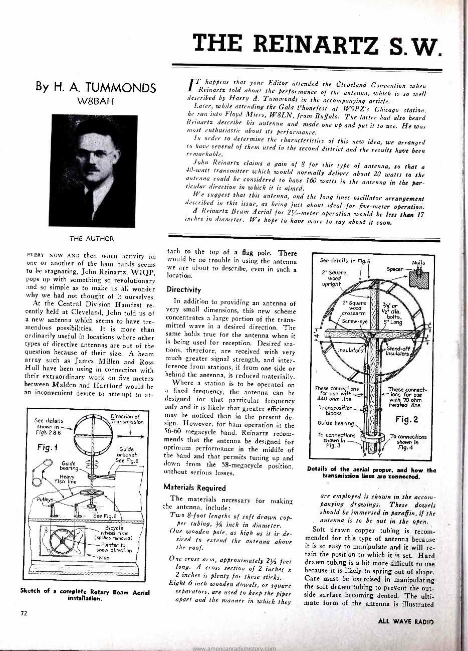
By H. A. TUMMONDS W8BAH
THE AUTHOR
EVERY NOW AND then when activity on one or another of the ham bands seems to he stagnating, John Reinartz, W1QP, pops up with something so revolutionary and so simple as to make us all wonder why we had not thought of it ourselves.
At the Central Division Hamfest re- cently held at Cleveland, John told us of a new antenna which seems to have tre- mendous possibilities. It is more than ordinarily useful in locations where other types of directive antennas are out of the question because of their size. A beam array such as James Millen and Ross Hull have been using in connection with their extraordinary work on five meters between Malden and Hartford would he an inconvenient device to attempt to at-
See details shown Fig's 2
Fig .
Pulleys
)..
, in --, a
of or I% Direction /,Transmission
.
Guide bearing
Heavy fish line
_ I'
\ %Ow" , ¡ t
- - Guide
bracket, See ßg.6 -
.0.--
S e Fig.6
! 'CV" r ,. .' Bicycle
wheel rims (spokes removed)
Pointer to show direction
"-Map
Sketch of a complete Rotary Beam Aerial installation.
72
THE REINARTZ S.W. IT happens that your Editor attended the Cleveland Convention when Reinartz told about the performance of the antenna, which is so well described by Harry !1. Turnmonds in the accompanying article. Later, while attending the Gala Phonefest at W9PZ's Chicago station,
he ran into Floyd Miers, W8LN, from Buffalo. The latter had also heard Reinartz describe his antenna and made one up and put it to use. He was most enthusiastic about its performance. In order to determine the characteristics of this new idea, we arranged to have several of them used in the second district and the results have been remarkable. John Reinartz claims a gain of 8 for this type of antenna, so that a 40 -watt transmitter which would normally deliver about 20 watts to the antenna could be considered to have 160 watts in the antenna in the par- ticular direction in which it is aimed. We suggest that this antenna, and the long lines oscillator arrangement described in this issue, as being just about ideal for five -meter operation. A Reinartz Beam Aerial for 2 / -meter operation would be less than 17 inches in diameter. We hope to have more to say about it soon.
tacle to the top of a flag pole. There would he no trouble in using the antenna ive are about to describe, even in such a location.
Directivity
In addition to providing an antenna of very small dimensions, this new scheme concentrates a large portion of the trans- mitted wave in a desired direction. The same holds true for the antenna when it is being used for reception. Desired sta- tions, therefore, are received with very much greater signal strength, and inter- ference from stations, if from one side or behind the antenna, is reduced materially.
Where a station is to he operated on a fixed frequency, the antenna can he designed for that particular frequency only and it is likely that greater efficiency may he noticed than in the present de- sign. However, for ham operation in the 56 -60 megacycle hand, Reinartz recom- mends that the antenna he designed for optimum performance in the middle of the hand and that permits tuning up and down from the 58- megacycle position, without serious losses.
Materials Required
The materials necessary for making the antenna, include:
Two 8 -foot lengths of soft drawn cop- per tubing, Y8 inch in diameter.
One wooden pole, as high as it is de- sired to extend the antenna above the roof.
One cross arm, approximately 2/ feet long. A cross section of 2 inches x 2 inches is plenty for these sticks.
Eight 6 inch wooden dowels, or square separators, are used to keep the pipes apart and the manner in which they
See details in Fig.6
2" Square wood
upright
Nails
These connections for use with
440 ohm line
Transposition blocks
Guide bearing
To connections shown in Fig. 3
These connect- ions for use
with 70 ohm twisted line
Fig.2
Details of the aerial proper, and how the transmission lines are connected.
are employed is shown in the accom- panying drawings. These dowels should be immersed in paraffin, if the antenna is to be out in the open.
Soft drawn copper tubing is recom- mended for this type of antenna because it is so easy to manipulate and it will re- tain the position to which it is set. Hard drawn tubing is a bit more difficult to use because it is likely to spring out of shape. Care must be exercised in manipulating the soft drawn tubing to prevent the out- side surface becoming dented. The ulti- mate form of the antenna is illustrated
ALL WAVE RADIO
www.americanradiohistory.com

ROTARY BEAM AERIAL Mercury grooves
Fig.3
To connections shown at "X"
in Fig.2
Stand -off insulators
Spring brass strips
3/8' wide
r
-ENE ?%IIIllilllÿ II1111111
L
v°
Mercury
8(/2" dia. wood disk ` Transposition
block (Shown on reduced scale)
To transmitter or receiver
How connections are made between the transmission line and aerial.
in Fig. 1 and it will be seen that the 8 -foot lengths have been bent into the form of a circle. This circle has an open mouth of 4 inches.
Forming the Tubing
The easiest way to bend the tubing is
to describe a circle, having a 33 -inch di- anieter, on the floor or wall. Then nails may be placed around this circle, about 4 inches apart. The tubing is then bent around these nails. Both pieces of tubing are treated in this same fashion. The two are then joined to the wooden dowels by any convenient method, such as a metal strip wrapped around the tubing, as shown in the accompanying drawings. Where maple dowels are not available,
Winding the loops . . .
NOVEMBER, 1935
sticks made of almost any kind of wood, / -inch square, will serve the purpose very satisfactorily, particularly if the out- side end is slotted so as to form a fit for the tubing itself. Separators of this kind are very easily made from a long length of / -inch square wood with holes made by a / inch bit, having their centers 6
inches apart. This long strip is then cut across the holes as shown.
The mast and cross arm are joined by
any convenient method and the use of two 4/ -inch machine bolts, as illustrated, has been found to work very well.
Next the two pieces of tubing are at- tached to the separators and the entire assembly is then placed on the mast and cross arm.
Assembly Details
The details for assembling the mast and cross arm are a matter of convenience and personal preference. It may, for in- stance, he simpler to extend the top of the mast above the loop and use a thirty - six inch cross arm. In this case, the sep- arators may be fastened to the surface of the mast and cross arm. It is sug- gested that the separators be drilled, be- fore the wood screws are put in place, to prevent splitting. This form of con- struction makes the slotting of the mast and crossarm unnecessary.
There is less tendency to split wood and the screws may be driven home with greater ease, if the screws are pushed into a cake of common soap before they are used. The soap acts as a lubricant.
Transmission Lines
Almost any form of transmission line can be used between this antenna and the
The loops are fastened . . .
. 1 3/8" d i a bolts
3/" to 4" long
Stop . To "Y" in Fig. 2
Metal or wood stop arm
Metal stop
II1111
Fig.4 Cross -
section of
upright
Loop to allow for
mast rotation
Stand -off insulator //,
To transmitter or receiver
How the base of the aerial is made. Note loop in transmission line.
output circuit of the transmitter. If a
440 -ohm line, such as is very readily made by the use of two stranded conductors and transposition blocks -the wires are not transposed in this instance -the con- nections are made as shown, at the left in Fig. 2. If a low- impedance line, such as a twisted pair, is to be employed, the connections are made as shown at the right in Fig. 2. A very simple method of making the connections between the line and the tubing is to utilize the large size National grid clips and when the correct position on the tubing has been found, these clips may be soldered directly to the tubing itself.
The clips should he put on the tubes, before assembly, if a low- impedance line is employed. It will he seen that the
The frame is added.
73
www.americanradiohistory.com

r 8' o'
Exact location of spacers is not important
- 6'
/ -
1/2" Sq. wood ( Maple preferred )
paraffined if for use in open
- - 6^- _ 8"dia. soft -drawn copper tubing
-- - _- _ f -. OE--- Method of 3 /8°dia. holes
6' to 8" dia. wood guide bearing
Saw through making spacers
centers of holes
Lag screws
4/41 X 1" or l/Z X 1 1/2" steel strip stock
Guide Bracket 0
Steel disk
Bearing ball
Metal strap
1° Iron pipe
(454 0.0)
Fig.6
Optional method
2' Sq. upright
Base Pivot
Pipe flange
Details of the spacers, guide
transmission line can be run along the cross arm to the mast and then down the mast to any convenient place above the station, where the twisted pair type of
line is employed. Precautions for prevent- ing the line becoming twisted are much easier provided than would be the case where the open line is employed.
The simplest form of a rotary antenna may be obtained by drilling a hole in the bottom of the mast and placing the mast itself over a metal pivot. A few sugges- tions for mounting the mast and support- ing it against the side of the building, as well as a simple means for rotation on a pivot, are all covered in the sketches.
bracket and base pivot.
Non -Twisting Feeders
Where the high- impedance, spaced line is used, the difficulty of having the line twisted is obviated by the arrangement shown in Fig. 3. In this case, the trans- mission line which runs parallel to the mast is terminated at two stand -off insu- lators. These insulators support two fingers which extend into the mercury which is placed in grooves, in a disc, made from a piece of paraffin- treated wood. A hood can be placed above the mercury container, to prevent dust or water ac- cumulating. By this arrangement it will he seen that the antenna can be rotated
continuously at will, without having any trouble with the feeders.
Where the twisted pair transmission line is employed, this device is unneces- sary, but a stop should be provided which will permit full 360 degree rotation of the antenna, but will prevent the trans- mission line becoming twisted more than a single turn, as shown in Fig. 4.
Direction of Transmission The direction of transmission with both
high and low impedance lines is shown in Fig. 1. An approximate idea of the dis- tribution for such an antenna, when it is in any given position, is shown in Fig. 5.
For all- around five meter activity, it would seem as though Reinartz has really provided something very satisfactory for us, in this antenna system.
Direction of Transmission
Max. gain. approx. 8
Aim Gain
at 45% approx.4
Fi .5
Showing direction of transmission and dis- tribution pattern of Rotary Beam Aerial.
"Battling the Ionosphere With Kilowatts" A NEW APPROACH to the transmission of short -wave radiotelegraph signals over long distances will be tried by RCA this Fall on the completion of a new 200 - kilowatt short -wave transmitter now un-. der construction at the company's sta- tion at Rocky Point, Long Island.
By means of this tremendous short- wave power, which is 5 to 10 times the intensity usually employed in interna- tional communication, it is proposed to "battle the ionosphere with kilowatts" and over -ride certain natural obstacles which to date have limited the signal strength under abnormal conditions. The Ionosphere
The ionosphere is an electrified region at the earth's outer atmosphere. Short- wave radio signals are reflected back and forth between this region and the earth in their passage around the globe. There are cycles in the daily condition of the ionosphere which make it necessary to use several wavelengths for long -dis- tance radio communication. There are also times of magnetic disturbances, when the turbulent condition of the iono- sphere causes absorption and dispersion of the radio signals and consequently re-
74
duced signal strength at the receiver. It is then that even highly concentrated radio beams become least effective.
What the engineers expect to deter- mine by means of the new 200 -kilowatt transmitter is whether the hours of use- fulness of one or more of the wavebands used in long -range communication may not be lengthened and the effects of mag- netic storms minimized by the use of in- creased power.
To Transmit on 28 Meters The new transmit *r will be operated
at first only on one wavelength, in the neighborhood of 28 mete:i. This wave has been selected as the trial one which promises the greatest general service- ability. It is expected that when radio signals from this transmitter are hurled against the ionosphere the greater power will cause them to be reflected back even during less favorable hours of opera- tion for that particular wavelength. Present -day commercial radio practice has been brought to a high degree of re- liability by directive transmission and the diversity system of reception. This new step by RCA looks toward further con- quest of the ether by enabling transmis- sion through severely disturbed periods.
In a word, it is proposed to meet na- ture in her occasional turbulent moods with the sheer brute force of man -made radio power. And apparatus more power- ful than any ever built for this service is being made ready to harness kilowatts to the task.
The new transmitter will be immedi- ately available on completion for com- mercial use in multiplex radiotelegraph transmission and facsimile transmission. It may ultimately be adapted to the transmission of addressed programs of voice and music to foreign countries.
EARLY TO RISE, LATE TO BED IF YOU WANT CHINA
"AMERICANS WHO want to hear broad- casts from China must get up early or stay up late. The waves of ZBW, Hong Kong, flash across their part of the world in the `dead of the night.' Re- cently, at 4:15 A. M., in New York. an announcer on the 8,750- kilocycle channel disclosed that ZBW was relaying a pro- gram from Daventry, England, but he did not say whether the broadcast was a direct relay or from a recording." (N. Y. Times).
ALL WAVE RADIO
www.americanradiohistory.com
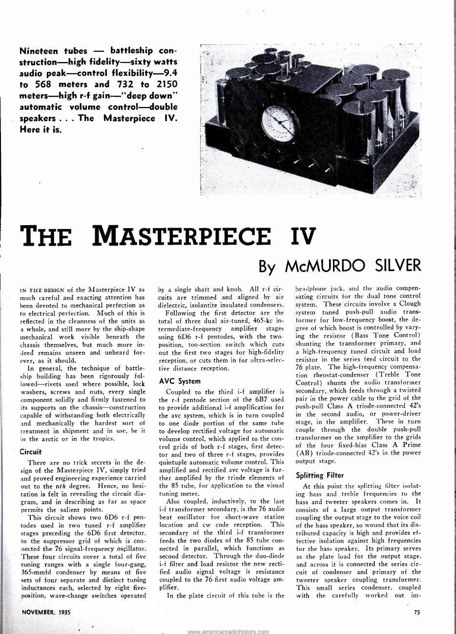
Nineteen tubes - battleship con- struction -high fidelity -sixty watts audio peak -control flexibility -9.4 to 568 meters and 732 to 2150 meters -high r -f gain -"deep down" automatic volume control -double speakers ... The Masterpiece IV. Here it is.
THE MASTERPIECE IV
By McMURDO SILVER IN THE DESIGN of the Masterpiece IV as much careful and exacting attention has been devoted to mechanical perfection as to electrical perfection. Much of this is
reflected in the cleanness of the units as a whole, and still more by the ship -shape mechanical work visible beneath the chassis themselves, but much more in- deed remains unseen and unheard for- ever, as it should.
In general, the technique of battle- ship building has been rigorously fol- lowed- rivets used where possible, lock washers, screws and nuts, every single component solidly and firmly fastened to its supports on the chassis -construction capable of withstanding both electrically and mechanically the hardest sort of treatment in shipment and in use, be it
in the arctic or in the tropics.
Circuit There are no trick secrets in the de-
sign of the Masterpiece IV, simply tried and proved engineering experience carried out to the nth degree. Hence, no hesi- tation is felt in revealing the circuit dia- gram, and in describing as far as space permits the salient points.
This circuit shows two 6D6 r -f pen- todes used in two tuned r -f amplifier stages preceding the 6D6 first detector, to the suppressor grid of which is con- nected the 76 signal- frequency oscillator. These four circuits cover a total of five tuning ranges with a single four -gang, 365 -mmfd condenser by means of five sets of four separate and distinct tuning inductances each, selected by eight five - position, wave -change switches operated
NOVEMBER, 1935
by a single shaft and knob. All r -f cir- cuits are trimmed and aligned by air dielectric, isolantite insulated condensers.
Following the first detector are the total of three dual air -tuned, 465 -kc in- termediate- frequency amplifier stages using 6D6 r -f pentodes, with the two - position, too -section switch which cuts out the first two stages for high -fidelity reception, or cuts them in for ultra- selec- tive distance reception.
AVC System
Coupled to the third i -f amplifier is
the r -f pentode section of the 6B7 used to provide additional i -f amplification for the avc system, which is in turn coupled to one diode portion of the same tube to develop rectified voltage for automatic volume control, which applied to the con- trol grids of both r -f stages, first detec- tor and two of three r -f stages, provides quintuple automatic volume control. This amplified and rectified avc voltage is fur- ther amplified by the triode elements of the 85 tube, for application to the visual tuning meter.
Also coupled, inductively, to the last i -f transformer secondary, is the 76 audio beat oscillator for short -wave station location and cw code reception. This secondary of the third i -f transformer feeds the two diodes of the 85 tube con- nected in parallel, which functions as second detector. Through the duo -diode i -f filter and load resistor the new recti- fied audio signal voltage is resistance coupled to the 76 first audio voltage am- plifier.
In the plate circuit of this tube is the
headphone jack, and the audio compen- sating circuits for the dual tone control system. These circuits involve a Clough system tuned push -pull audio trans- former for low- frequency boost, the de- gree of which boost is controlled by vary- ing the resistor (Bass Tone Control) shunting the transformer primary, and a high- frequency tuned circuit and load resistor in the series feed circuit to the 76 plate. The high- frequency compensa- tion rheostat -condenser (Treble Tone Control) shunts the audio transformer secondary, which feeds through a twisted pair in the power cable to the grid of the push -pull Class A triode -connected 42's in the second audio, or power- driver stage, in the amplifier. These in turn couple through the double push -pull transformer on the amplifier to the grids of the four fixed -bias Class A Prime (AB) triode -connected 42's in the power output stage.
Splitting Filter At this point the splitting filter isolat-
ing bass and treble frequencies to the bass and tweeter speakers comes in. It consists of a large output transformer coupling the output stage to the voice coil of the bass speaker, so wound that its dis- tributed capacity is high and provides ef- fective isolation against high frequencies for the bass speaker. Its primary serves as the plate load for the output stage, and across it is connected the series cir- cuit of condenser and primary of the tweeter speaker coupling transformer. This small series condenser, coupled with the carefully worked out im-
75
www.americanradiohistory.com

pedance relations, effectively and auto- matically removes the tweeter from cir- cuit on low frequencies but brings it into play from 3,000 cycles up.
Power Supply
The power supply involves a very large and heavy power transformer operating from any 105- to 125 -volt, 50- to 60 -cycle power line (or through avail- able reducing transformer, from 210- to 250 -volt lines) which has three secon- daries. One secondary supplies 6.3 volts at 7.5 amperes to the tubes of the tuner and amplifier. A second lights the 5Z3 rectifier filaments, and the third provides high voltage to the 5Z3 plates for rectifi- cation and filtration into the final plate and grid voltages for the receiver. This transformer is provided with an electro- static shield between primary and secon- daries to drain off power -line noise and prevent it getting into the receiver cir- cuits.
Two 5Z3 full -wave rectifier tubes are used, connected in parallel, to supply the 250 milliamperes at 388 volts required to operate tuner and amplifier. Thus, each tube is operated at just half its rating, to insure long and trouble -free life, although one would do the work, but with no safety factor whatsoever.
The filter system is choke input, em- ploying one low- resistance choke, and the tweeter and bass speaker fields. The circuit diagram shows a series -pair in- put condenser, which, however, being of only .25 -mfd. capacity (800 -volt rating) to eliminate mechanical vibration in the input choke, is too small to function as a starting condenser, so that though diagrammed otherwise, the filter system is actually choke input -absolutely neces- sary for the well -nigh perfect voltage regulation necessary to powerful audio amplifiers.
Automatic Voltage Regulation Following this choke is 16 -mfd of
475 -volt automatically self -healing wet
76
The with
husky "power" chassis, containing the double- rectifier power -supply unit special filter system, and the 35 -watt Class AB amplifier which
drives the dual dynamic speakers shown below.
electrolytic capacity; then 12 -mfd of self - regulating filter capacity. After this is the third section of the filter, the bass speaker field obtaining 12 watts excita- tion, followed by 18 -mfd of self- regulat- ing capacity. These two self -regulating and total of three self -healing electrolytic condensers are just another fine point of the design. They temporarily absorb the voltage developed as a result of the quick heating of the 5Z3 rectifier tubes, which develop full voltage before the heater tubes are warmed up enough to absorb it as they do in operation. Dur- ing this time interval of twenty to thirty seconds, the second two filter condensers act as absorbing resistors, but as soon as operating voltage reaches normal, they cease to draw current and resume their function of pure filter capacity. Thus by this new system, all strain on circuit components during "warming -up" is completely eliminated, while filter con- densers being automatically self -healing, remove all possibility of breakdown in service.
"High- Low" -The giant and the mid- get: one for bass and one for treble. Together they re- produce a wide range of audio fre- quency tones.
Fixed -Bias Output Stage Substantially fixed bias' for the 35 -watt
Class A Prime output stage is obtained through the voltage drop across a re- sistor in the negative power supply lead, through which the entire current for the receiver, amplifier and bleeder network is drawn. During peak signal condi- tions the maximum voltage variation across this resistor due to changing cur- rent through it is such a small percentage of the total current flowing through it (and bias voltage developed across it) that the bias voltage variation is negligiblé, which permits of obtaining 35 to 60 watts of undistorted power output from the power output stage.
Gain Ratios and Inherent Noise In the perfect radio receiver the final
limit of sensitivity should be, but sel- dom or never is, the limit set only by thermal agitation in the input circuit - the constant movement of the electrons making up a supposedly solid copper wire in the first tuning inductance. The at- tainment of this connection is almost im- possible to superheterodyne receivers because of noise introduced in the first detector -oscillator frequency conversion function. Quantitively this noise is about 4.0 microvolts for pentagrid converters (2A7 -6A7 tubes) ; about 2.0 micro- volts for ordinary separate detector - oscillator tube combinations, and about 1.0 microvolt for suppressor -grid in-. jected oscillator- detector circuits.
From this it is obvious that the in- herent circuit noise will be overwhelm- ingly great in relation to received signal when any attempt is made to receive signals in the range of / to 4 microvolts absolute input to the receiver. Equally obvious, any attempt to reach such usable sensitivities by increasing i -f amplifica- tion cannot remedy this condition, and will, in fact, only add i -f amplifier noise to already ruinous oscillator- detector
ALL WAVE RADIO
www.americanradiohistory.com
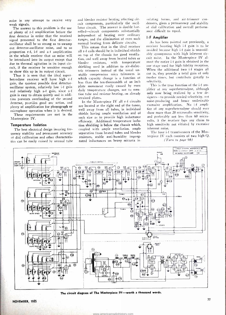
noise in any attempt to receive very weak signals.
The answer to this problem is the use of plenty of r -f amplification before the first detector in order that the received signal presented to the first detector - oscillator shall be so strong as to swamp out detector -oscillator noise, and to so proportion r -f, i -f and a -f amplification in the whole receiver that no noise will be introduced into its output except that due to thermal agitation in its input cir- cuit, if the receiver be sensitive enough to show this up in its output circuit.
Thus it is seen that the ideal super - hetrodyne . receiver will have high r -f gain, the quietest possible first detector - oscillator system, relatively low i -f gain and relatively high a -f gain, since a -f gain is easy to obtain quietly and in addi- tion prevents overloading of the second detector, provides good avc action, and plenty of amplification for phonograph or microphone operation when it is desired.
These requirements are met in the Masterpiece IV.
Temperature Isolation The best electrical design insuring fre-
quency stability and permanent accuracy of dial calibration and other characteris- tics can be easily ruined by normal tube
and bleeder resistor heating affecting cir- cuit components, particularly the oscil- lator circuit. The answer is double bar- relled- circuit components substantially independent of heating over ordinary ranges, and the elimination of even such normal heating from delicate circuits.
This means that in the ideal receiver all r -f coils should be in individual shields on top of the chassis for good ventila- tion, and well away from heated tubes or bleeder resistors, with temperature shielding used in addition to air- dielec- tric trimmers instead of the usual un- stable compression mica trimmers in
which capacity change is a function of
less than the ten -thousandth of an inch
plate movement easily caused by even
daily temperature changes, not to men- tion tube and resistor heating, on already strained plates.
In the Masterpiece IV all r -f circuits are located at the right end of the tuner, well away from all tubes, in individual shields having ample ventilation and of
such size as to provide high inductance efficiency. Additional temperature isola- tion shielding is below the chassis which, coupled with ample ventilation, ample separation from heated tubes and bleeder resistors, stable anti -humidity impreg- nated inductances on heavy micarta in-
dilating forms, and air -trimmer con- densers, gives a permanency and stability of dial calibration and overall perform- ance difficult to equal.
I -F Amplifier As has been pointed out previously, a
receiver boasting high i -f gain is to be avoided because high i -f gain is unavoid- ably synonymous with high inherent cir- cuit noise. In the Masterpiece IV al- most the entire i -f gain is obtained in the one stage used for high- fidelity reception. When the additional two i -f stages all cut in, they provide a total gain of only twelve times, but contribute greatly to selectivity.
This is the true function of the i -f am- plifier of any superheterodyne, although only now being realized by a few de- signers-to provide needed selectivity, not noise -producing and hence undesirable excessive amplification. No i -f ampli- fier of any superheterodyne should ever show more than 20 microvolts sensitivity, and preferably not less than 60 micro- volts, if the receiver lays any claim to high sensitivity not vitiated by excessive inherent noise.
The four i -f transformers of the Mas- terpiece IV each consists of two high -Q,
(Turn to page 96)
GROUND I F NG ANT
SPORT ANTO-
MMVCMtD SNITCH
PNONO
CIRCUfT DiAGRAU MASTERPIECE IN +7.t fowl c. Mt YAW SILVER C'ORR INO
r p
ali I !r! 6 I I ®, C C 4 NTCNNA i ; Gr R6
eQ- l/.R'qf
7 !
)3 arin C D t
The circuit diagram of The Masterpiece IV -worth a thousand words.
NOVEMBER, 1935 77
www.americanradiohistory.com

A DOCTOR AN AMATEUR
Dr. Burton T. Simpson Station W8CPC
By FLOYD MIERS, W8LN - Buffalo
DR. BURTON T. SIAIPSON, W8CPC, is one of the most enthusiastic radio amateurs in the United States. He entered the amateur ranks in 1926 with a modest Hartley transmitter and since that time has kept pace with the advancement of the art. He was one of the first ama- teurs in his territory to successfully put a crystal -controlled transmitter on the air and was the first amateur in Western New York to obtain an extra first class amateur ticket. At the present time Dr. Simpson has one of the outstanding ama- teur stations of the country, a photo- graph of which is shown on this page.
The "Shack"
The "shack" is located in a large bed- room on the second floor of his home with a good sized adjoining closet for a
work shop. There are two transmitters with identical circuits, viz., 802 oscilla- tor, 210 doubler, 210 buffer, a pair of 830's for amplifier, modulated Class C by a pair of 845's. The final linear am- plifier consists of four 852's push -pull parallel. One transmitter, using a 160 - meter xtal, is used for 40 -meter cw and 8 -meter fone, and the other, using a 40 -meter xtal, is used for 20 -meter cw and 20 -meter fone. Both transmitters have one kilowatt input on cw and a half -kilowatt on fone. The antenna is a split Hertz, 33 -foot flat -top on each side of the center, fed with 45 -foot feeders and 40 feet off ground. This type of an- tenna is used because it works well on the three bands mentioned and also be- cause of limitation of space in the back yard.
Station W8CPC- Transmitters and receivers galore! One transmitter is used on the 20 -meter band only. The other is used on 40 and 160.
78
Dr. SIMPSON
The Receivers
The receivers used at W8CPC are : a seven -tube home built superheterodyne with a Peak pre -selector, an RME -9 and an HRO. There are three oscillographs: a National, connected with transmitters to check the outgoing signals; an RCA connected with the receiver to check the incoming signals; and a Kaltman and Romander, connected with the audio sys- tem. The rack -and -panel job contains a 100 -kc xtal bar oscillator in connection with a frequency meter, also the audio amplifier and a mixer system. The mike used at present is a Turner xtal.
In the work shop the five -meter re- ceivers and transmitter are located. The doctor is an enthusiast on the ultra- high- frequencies and is president of the Omega Ti u Five Meter Club.
Amateur Radio As Hobby When the doctor is asked; what he
thinks of amateur radio as a hobby he becomes serious and will say that it is the finest hobby in existence, but even more than that -it is almost a liberal education,
Dr. Simpson is at present intensely in- terested in the formation of fone or- ganizations;. He has been partially in- strumental in the organization of associa- tions in the following ARRL Divisions: Atlantic, Canadian, New England, West Gulf, Delta, Midwest, Central and Da- kota, and is ak present the president of the Atlantic Division Rao iofòne Associa- tion. When asked'ithe object of forming fone organizations he will say, "To pre- serve amateur radio. '
With the advent of a great group of short -wave listeners, the conduct of the amateur using radiofone is being sharply scrutinized. Ungentlemanly transmis- sions will not be tolerated. In the past the amateurs have policed themselves.
ALL .WAVE RADIO
www.americanradiohistory.com

More recently the government has made
some stringent regulations and has es-
tablished monitoring stations to check and penalize the amateurs who commit any infraction of the rules.
In the preamble of the constitution of
every fone organization may be found the following statement, "We, radio amateurs interested in radiotelephone, being desirous of upholding a high standard of this branch of the radio art, do establish this constitution." There is also a code of ethics by which every member agrees to abide. If every ama- teur would join the fone association and live up to its ideals there would be little to fear about losing our status and much to be gained.
Dr. Simpson not only likes to contact amateurs over the air, but enjoys meet- ing them personally. Therefore, he is a
confirmed attender of hamfests and con-
ventions. To date this year he has at- tended more than twenty of these func- tions.
Dr. Simpson's Activities
Perhaps you would like to know some- thing of the doctor's activities aside from amateur radio. Dr. Simpson is the Di- rector of the New York State Institute for the Study of Malignant Diseases. In
plain words, he is the head of one of the largest institutions in the world for the study and treatment of cancer. The In- stitute has all the modern facilities for research and the largest amount of
radium of any single institution in the world. Experiments are being carried on with ultra -high frequencies in the treatment of cancer, so you see that the doctor's knowledge of amateur radio has been of help in his own work.
Dr. Simpson does not confine his at- tendance to radio conventions but has frequently to attend medical and scien-
tific conventions. He has attended and read papers at several international con- gresses in Europe and is known through- out the world as an authority on cancer. While the doctor does not practice medi- cine in Buffalo, he acts as consulting physician to a host of amateurs through- out the United States and Canada, for when an amateur sees in the call book that he is working an M. D., the ama- teur immediately takes the opportunity to get a little free medical advice! If you should contact W8CPC on the air, ask him to relate some of his amusing experiences along these lines.
The doctor has a favorite remark which he takes every opportunity to ex- press, viz., "There is no such animal as
a `cw' man or `fone' man -we are all
ONE OF THE best after- dinner speakers and story tellers we have heard in many moons was brought to our attention when we were among the "stuffed shirts" at the banquet which terminated the Central Division A.R.R.L. Convention, recently held at Cleveland. We refer to Mr. Bail, Director of the A.R.R.L. for the First District. What's more, he
claims that the yarn he told is a true story. As we remember it:
The Radio Inspector for the First District has his headquarters in Boston. The present encumbent is a rather pleas- ant but retiring gent by the name of
Kolster. Brockton is a Massachusetts city, famous, among other things, for its Annual Fair. It is not too far from Boston and Mr. Kolster is reported to
have taken himself to the Brockton Fair. Among the exhibits a certain amount of
radio equipment was on display and
among the radio equipment there was a
buzzer hooked up with a key, of the type
employed by amateurs for code practice. Naturally the Radio Inspector gravi-
tated to the radio exhibit and ultimately began toying with the key. A young fellow of some sixteen summers listened to the hiiz"er for a time and then re- marked that he, too, knew the code. Mr. Kolster was pleased and turned the key
over to the young man who went about his transmission with great zest. After
NOVEMBER, 1935
A GOOD STORY batting out quite a little message he
signed off with WIVH. If our memory has tricked us regard-
ing the call, we are sorry. It is unim- portant except for the fact that the kid used a two -letter call. Looking at the boy rather quizzically, the R. I. seemed to be of the opinion that he was rather young to he the possessor of such an old call.
On being interrogated, the youngster told Mr. Kolster that he had never taken a license examination and that he had seen a lot of call letters in a call book and had appropriated one for himself which he thought had a rather nice
swing. Further interrogation brought out the
information that there -was very little chance of his being caught and sent to jail for operating his station without a
license; that the Radio Inspector was an old fogey, who spent all his time in Bos- ton and would not be able to catch up
with our young friend even if he did
get to Brockton. Mr. Kolster was then reported to have
said: "I don't suppose you have any idea
who I am, do you" The youth agreed that he didn't. After the Federal Badge, on the inside of the R. I's. coat had been displayed. the boy got off some such con- versation as this:
r--
AMATEURS." If one gets his kick out of cw that's his business; likewise for fone. However, the doctor believes that the fully rounded amateur should take advantage of all the art offers and operate both fone and cw. Another be-
lief the doctor has is that every amateur should be a member of the ARRL. Were it not for this organization there would be no amateur radio today. It is con-
ceded that the FCC recognizes the League as the spokesman for the ama- teur. As members of the League we can therefore cast our vote and have some- thing to do with the recommendations for the best interest of amateur radio.
Frequency Allocations
The doctor is of the opinion that we are more liable to lose some of our fre- quencies than we are to gain any. The television group is after our 56- megacycle allocation, and if the broadcast listeners become antagonistic, we may lose more. The Government will not tolerate a nui- sance and it therefore behooves every amateur to be meticulous in his operat- ing practices. There has been some dis- sention in the amateur ranks, but this is
a mistake and we should stand united if
we wish to keep the finest hobby in the world.
"Don't some funny things happen when you least expect them? Here I am tell- ing you all about myself not having a
license and you being an old fogey and never getting to Brockton and all that. You know, I never thought about what I
was doing. Well, I didn't know who you were and I don't suppose you have an
idea who I am, do you ?" Mr. Kolster was taken a bit back by
the question and agreed that he did not have any idea who the youth was.
"That's a swell break for me!" said the boy, as he turned on his heel and dashed out of the building.
SEES SHORT -WAVE PROMOTING GOODWILL BETWEEN NATIONS
EXTENDING felicitations to the Radio Fel- lowship at Beverly Hills, Calif., Secre- tary of Commerce Daniel C. Roper, de-
clared that the Fellowship has splendid purpose in attempting to create a better understanding between the nations of the
world through the medium of radio. "The education of the people in the
use of short -wave broadcasting," Secre- tary Roper said in a letter to M. H. Ryder, Chairman of the organization, "will provide another means of promot- ing good -will among the people of the dif-
ferent nations."
79
www.americanradiohistory.com

A Five -Meter "Long Lines" Oscillator A newly developed method for using this system. Marked stability and in- creased efficiency are its features, not to forget the simplicity of the oscillator and its low cost.
By ED. RUTH, W2GYL
T}[I: ACCOMPANYING drawings illustrate the simplicity as well as the extreme portability of a newly developed method for using the "long lines" oscillator which was introduced to ham radio in its first practical form by George Shuart, W2AMN.
The unit illustrated and described here is actually in use in the station operated at his home, by Arthur H. Lynch, 1V2I)KJ. In this case the oscillator is hung from the picture molding and is several feet away from the remainder of the transmitting equipment. It will be observed that two rather heavy twisted pairs are used to feed the filament cur- rent and the plate voltage from the reg- ular power supply.
Screw -eye for
hanging from
picture molding
Choke, 2i /2 Milli -
henries
Lead to choke
Fig.1
FRONT VIEW
National stand -off insulators Type 65 -1
Fahnestock clips
6'
+r.,- a_A11.
4'
o o
, -- - 5 . 4'-
'%
Flat head wood
screws
National grid clips
(Large size)
soldered together to form shorting
bar
Leads secured
by insulated
tacks
Lead to resistor
SIDE VIEW
3/4' Vacuum
tube sockets
Flat head wood
screws
Constructional details of oscillator used at
the "long lines" W2DKJ.
The "Long Lines" oscillator mounted in the baggage com- partment of an auto. It has portability plus.
Reduces Broadening Effect The theory of the "long lines" oscillator
is now fairly well understood and it is rec- ognized to provide amateurs with a trans- mitter of marked stability at but a frac- tion of the cost of a crystal -controlled transmitter. As a matter of fact, it may he constructed at little more expense than the conventional type of circuit. In ad- dition to providing greater efficiency at the transmitter, as far as output power is concerned, this arrangement has the dis- tinct advantage of concentrating the wave from the transmitter, by reducing the broadening effect which is apparent in all frequency -modulated transmitters. This means that many more stations may he operated in a given frequency spectrum without interfering with each other than would be possible if the older forms of modulated oscillator transmitters were employed.
Mechanical Details
The mechanical details given in the accompanying sketches cover a particu- lar type of oscillator for which parts are quite generally available. It will be ob- served that the four long lines are made up of 7, inch, OD copper tubing. The rods in the unit shown here have been silver plated to reduce their high -fre- quency resistance to a minimum. Each pair is spaced 1 inch apart. If other di- ameter tubing is employed, the spacing be- tween centers should be twice the outside diameter of the tube. The spacing be- tween the two pair, however, is rela- tively unimportant. The two pair may be placed as close together as desired, pro- vided sufficient room is left for the locat- ing of the vacuum tubes. The dimensions given are suitable for use with all of the tubes now in general use on five meters.
Insulation
The experienced radio man will recog- nize that simplicity and economy has been
exercised in the design of this Unit, but the efficiency of the unit is maintained at a maximum because of the intelligent ap- plication of the most suitable types of insulators in places where they will he effective and the use of ordinary insulat- ing material where losses would not he likely to occur. The four lengths of metal tubing are slipped over the tops of four stand -off insulators. The reason for using high -grade insulators at this point, is be- cause leakage loss would be noticeable under other conditions. It will be ob- served that the two vacuum -tube sockets are also of the highest grade, being Stea- tite sockets with guide grooves. To in- sure perfect continuity of the circuit in this area, heavy copper braid is soldered directly to the contact points on the sock- ets, as well as directly to the base of all four of the oscillator rods.
Since the upper extremities of the rods are actually cut out of circuit by the shorting bars of the grid and plate cir-
PARTS LIST
1 -Piece of board, any convenient width, about 48 inches long and 4 inch thick.
2- Wooden blocks inch by 6 inches by 5 inches (approximate).
4- Lengths hard -drawn copper tubing, inch outside diameter.
4-1 inch No. 8 brass, flat -head wood screws.
4- Fahnestock clips, any available size.
4- National Stand -off insulators, Type GS -1.
6- National Grid Grips, Type 12. 2- National low loss, Steatite Sockets, with mounting bushings.
1- National R -F Choke, Type R -100. I foot % inch copper braid. 1- 10,000 -ohm, 10 -watt resistor.
ALL WAVE RADIO
www.americanradiohistory.com

tufts, it is not necessary to use more than ordinarily good insulating material and in this case, wood serves the purpose very satisfactorily.
Naturally, all of the wood used in this assembly should be suitably kiln- dried, and if extra protection is desired, it may be painted with hot paraffin.
The simplest form of clip for use in
connection with this arrangement seems to be a large size grid clip. Two of these soldered together, form an ideal shorting bar for the grid circuit, and two similarly soldered, form such a bar for the plate circuit. The two clips for the transmis- sion line are, of course, not connected to- gether and they may be soldered directly to the end of the line itself, or the .002 mica isolating condensers may be placed between them and the line.
Coupling
When the type 45 tubes are used in the transmitter, the position of the various units in connection with the oscillator will be as illustrated, for a frequency of ap- proximately 57 megacycles. In this case,
the coupling between the transmission
line and the plate circuit, as shown in the photograph, is just about correct for a
440 -ohm line, such as is made up by the use of transposition blocks and heavy stranded enamel wire. If a low -im- pedance line (70 ohms) is employed, the distance between the plate shorting bar and the antenna coupling clips, will be
reduced to an inch or less. Where 801 tubes are used in the os-
cillator, it will be found that the length of the active portion of the rods in both plate and grid circuits, will be somewhat greater than is shown here for the same frequency.
Duplexing
Another very satisfactory method of
employing this oscillator is to locate it within just a few feet of the antenna it- self and by so doing, the receiving equip- ment can be kept well out of the oscil- lator field, which permits the operator to maintain duplex QSOs with stations very much closer to his own particular fre- quency than would be possible otherwise. A separate antenna is used for the re- ceiver, in all regular duplex work.
To antenna
Rear rods Front rods
.002 mfd. mica cond.
Connect to
resistor when A.C. filament supply is used -
24/2 Mh. choke Hi9h-
efficiency tube
sockets
-41,H11----
--
l:®1 I ®t
II .: III tI,hI .1 _
I" for 70 ohm
line
6 "for 440 ohm
line
Fis. 2 For D.G.
filament supply. (Disregard for A.C. operation)
Plate supply
Fahnestock clips
20 ohm center tapped resistor
Filament supply ( A.C. or D.C.)
Complete wiring of "long lines" oscillator.
DESIGN OF TRANSFORMERS FOR AMATEURS
AMONG THE MANY requests which the National Bureau of Standards, Wash- ington, D. C., receives for technical in- formation are a considerable number from amateurs who require design data on power transformers for various pur- poses. It is not practicable to spend the time of the staff working out individual design problems which are not of public interest. For a number of years, such requests have been partially covered by
sending a very short typewritten mem- orandum on general principles of trans- former design. The use of this informa- tion, however, involved calculations with which many amateurs are not familiar, and left rather too much to the judg- ment of the individual.
In seeking for means to improve this memorandum, the possibilities of using curves or graphs to reduce computa- tion were considered. By the use of logarithmic and semilogarithmic crosssec- tion paper it has been possible to reduce all of the graphs except one to straight lines, and to reduce the computation to a very small and simple matter. For ex- ample, the designer can tell at a glance how much iron and how much copper will be needed for a transformer of any rated output between 1 volt ampere and 10 kilovoltamperes (that is, 1 watt and 10 kilowatts, at unity power factor) ;
how large must be the cross section of the core; how many turns of wire must he
used per volt ; the sizes of wire; the regulation ; the values of the iron loss
Nelson Case and George Hicks, radio announcers of NBC, after the broadcast of the Army maneuvers near "Hill 300," Sterlingville, N. Y. Note the Army
Tanks in the background.
NOVÈMBÈR; 1935
and the full -load copper loss; and the efficiency at full load. These labor -sav- ing graphs are the basis of Circular C408 which has just been issued by the Bu- reau under the title, "Information for the Amateur Designer of Transform- ers for 25- to 60 -Cycle Circuits."
The circular includes definitions of terms used in connection with transform- ers, and states very briefly the mathe- matical relations on which the design pro- cedure is based. It gives information on kinds of magnet wire suitable for use in making transformers, and out- lines methods of constructing the wind- ings and of forming the core. Special in- formation is given for cases which present unusual difficulties, namely, windings for large currents at a low voltage, wind- ings with low- voltage taps, and trans- formers to have good regulation with inductive loads at low power factor. Al- though the method of design is intended primarily for the usual frequency of 60 cycles, it may be readily modified so as to be applicable to 25 cycles and to 50 cycles. .
As a result of correspondence between the Bureau and the makers of magnet wire and of transformer steel sheets, it has been possible to include in the cir- cular a list of names and addresses of concerns willing to sell small quantities of material to the amateur constructor. Suggestions are given in the circular as to local sources of wire and of insulating varnish.
Copies of this circular are available from the Superintendent of Documents, Government Printing Office, Washington, D. C., at 5 cents each.
81
www.americanradiohistory.com

THE FOOTLOOSE REPORTER
SPY CHASER WITH MESSRS. Mussolini, Laval, E and Hitler looking at one another v askance, whilst telling what the oth can not do and then going ahead and ing whatever they please, is it any w der that thoughts of 1914 crop up? have been told that this next war is be fought in the air and so when we r across Ralph Sayres our conversati turned to going on the air, just in c all these European rumors come to pa
In the world -wide unpleasantness eighteen years ago, Sayres did share towards making the world sa for democracy in this country's Na Having grown up with Al Grebe a Arthur Lynch, it is small wonder th he should have been a radio operat even before the Germanic Egoman chose Gott as his Ally and set out to things to civilization in general. In fa Ralph had an amateur transmitter wh it was no heinous crime to work whatever wavelength you desired!
So when Mr. Wilson finally decid that we just could not stand it an longer, Sayres enlisted in the branch the service as a radioman. After son preliminary training he was put on torpedo boat destroyer and found o that the North Sea in winter is ju about as cold as Admiral Byrd says it down below in Little America. Ye indeed; the ship he was on ran into couple of submarines and sent them t depths their designers never intende them to dive . .. sent them there perma nanently. Then he was assigned to converted yacht and -but Sayres say that there was not a great deal of excite ment in all that ... it was much more s when one of his shipmates came aboar one night with a pint in each eye and couple more inside his blouse. Thi exhilarated gentleman was hungry an so went to the ship's galley, where, bein refused food, armed himself with butcher's knife and a cleaver and ra amok.
Then Sayres was assigned to a con verted yacht patrolling the American coast, at the time when German sub marines had crossed the Atlantic. When he first went 'aboard this vessel, he thought that the half -kilowatt outfit was fine and continued to think so until one day his skipper commented on the fact
den that whenever the key of the transmitter ery was held down for an appreciable time it ers slowed up the ship! This was because do- the transmitter put such a heavy load on- on the ship's power plant that there just We was not enough current to go around ...
to how come, we don't know, but that's the an dope. on Later on Sayres was transferred to the
ase Naval Intelligence outfit and it was his ss. job to track down radio stations that of were operating without governmental
his permission and so might be in the hands fe of spies. He told us that he had on an
vy. average of five assignments per day and nd that the majority of these were nothing at more than figments of imagination on the or part of over -zealous neighbors. is However, one time the hospital at
do Lakehurst, N. J., called up and reported ct, that they had been hearing something en that sounded like dots and dashes on on their telephone and could not account
for it. Sayres and his strong -arm squad ed were rushed out to Lakehurst for an im-
y mediate investigation. He arrived in the of late afternoon and was told that during le certain hours of the day whenever the a telephone receiver was removed from its
ut hook and before the operator would ask st for the number, these peculiar signals is would be heard. This did sound like s, the work of spies- transmitting at regu- a lar times daily. However, nothing un- o toward was heard that afternoon nor d during the night. Next morning a little - after ten o'clock, the strange signals a commenced. They were intermittent and s in neither the Morse nor Continental
codes. The office of the telephone corn - o pany was visited and other lines in- d spected, but the line to the hospital was a the only one on which signals were heard s . . . and then only when the line was d "open." After listening to the meaning - g less dots and dashes and trying to put a some meaning into them, the idea sud- n denly came to Sayres that these electri-
cal impulses resembled the intermittent - operation of a stock -market ticker! He
called the telephone company's office and - discovered there was a ticker at a nearby
hotel and after a little search found that the lines to the hospital and hotel ran parallel for a short distance and that the electrical impulses of the hotel line were being induced in the hospital's line. Natu-
82
rally the signals were only present dur- ing the time the stock market was open.
The equipment that Sayres carried about consisted of a small, super- sensi- tive receiver with a loop antenna for locating a transmitter that was operating illegally. On local assignments this apparatus was installed in an automo- bile and Sayres with his "gang" were liable to be sent out any time of the day or night. Usually the checking -up of the story took but a comparatively few hours, but one job, Sayres told us, took about a month.
Signals, which weré unauthorized, were traced to a portion of Long Island that was as wild and desolate, as though it were hundreds of miles from New York. Sayres and his crew sped to the locality and started their search for a house with the usual tell -tale antenna. They fruitlessly inspected every building in the neighborhood and when reporting their negative findings to headquarters were told that the same signals on a dif- ferent wavelength had been located a few miles north.
Sayres adjusted his receiver to the new frequency, picked up the signals, got the direction and the crew set off. They had traveled a short time, when the sta- tion shut down and so left them without a definite destination. They cruised about the place where they thought the station might be, but with no results. Not until the following night were any more signals picked up from this one particu- lar station and then they came from an- other direction altogether. Sayres then came to the conclusion that the mysteri- ous transmitter was mounted in an auto- mobile, fot there was no doubt that the signals were from the same set.
That he was correct in his deduction was evidenced by the fact that for several days, these same signals were traced to many different parts of the Island The Naval !authorities then issued warnings to the police to keep a lookout for a suspicious looking automo- bile with radio apparatus installed in it. From that time on Sayres' life was made even more miserable, for he and his crew, who were, of course, not dressed in uni- forms, were stopped often by the police
(Turn to page 94)
ALL WAVE RADIO
www.americanradiohistory.com

THE BOSCH THE REPORT ON this receiver should prove of special interest. It is the first metal -tube set we have placed on actual test. The results obtained can he applied only to the Bosch Model 575, but at the same time they are some indication as to
what may he expected from metal tubes in any well -designed set.
Mechanical
As may he seen from the accompany- ing illustration, there are tour control knobs. From the left, the first knob is
on -off switch and volume control. The second knob operates the hand -selector switch. The third knob, of the dual - speed type, controls tuning. The fourth knob operates the tone control.
Both volume and tone controls arc well graduated and quiet in operation. The band -selector switch is inclined to
he stiff, but there appears to be no doubt that good contact is made, which is the important thing.
There are three wave -hand position,. Each wave band is provided with a sepa- rate scale on the airplane -type dial.
The 540- to 1800 -kc scale is black and
is marked in both meters and kilocycles. The 1800- to 5800 -kc scale is green and
is marked only in kilocycles. The 5800 -
to 18,000 -kc scale is red and is marked in kilocycles, with the wavelength in
meters spotted for each important band. The small telephone -switchboard type
pilot light just to the left of the band -
selector switch changes in color from white, to green, to red, for the succes-
sive switch positions. Since the two
higher frequency dial scales carry these
colors, one can tell immediately to which
hand the receiver is set for.
off
METAL -TUBE SET
Dial calibration is excellent. 'There is
slight backlash in the "second- hand" dial pointer, but not enough to cause in- accuracies in readings.
Electrical
Selectivity in the broadcast hand is
good, but not excellent. On the whole, it appears to be adequate in all hands.
Sensitivity is better than good. which may account for the apparent slough -off in selectivity at certain frequencies.
liBand
Selector
(11 s
iwifch
1800 Kc. ss R.F.
Tube
1800 f o
6000 Kcs
6000 Kc. to
18.500 Kc.
m
I.F. Transformer
Oscillator Mixer-
465 Kc.
I.F. Transformer
I.F. Tube
465 Kc.
Def.- A.V.C.
Automatic Volume Control Line
A.F. Tube
411)
Loud Speaker
Power Tube
Tone Control
Volume Control
Simplified block diagram of the Bosch Model 575 Metal -Tube Receiver. coil complement is not shown.
NOVEMBER, 1935
Complete
MODEL 575 I ,' h on this receiver were ',undiluted
Burin:: a week when atmospherics were excessive. However, switching hack and forth hetu ern a receiver "standard- arid
the Bosch set. brought tint the tact that the latter %%:Is the quieter ut the two. On one evening it was impossible to 11sr
the "standard." the nuise was so terrific, xhrreas the lins, h receiver dug down un der and brought up some good signals.
The undistorted audio output of this receiver is given as 2.S Warts. with a
111;1 \111111111 ,IIItpllt of .l..i N':Itts. This N':ls
Wit t ht't kr,I, hilt sounds reasonable.
The Circuit There i nothing unusual about the
circuit of the Model 575. 'There is a
radio- trequency pre -amplifier stage using a h1K7 tithe. preceding, the mixer- oscilla- tor. This is shown in the block dia _ram on this page.
The muer- oscillator tube is a OAR.
The mixer section teed% a single stage Irl-
terrnediate- trequency amplifier using a
t)k7 tube. The signal front the i -f am- plifier is fed to the hilt) duo -diode tube.
The dindes of the t) H t) arc connected together and serve as second detector and automatic volume lontrol. The direct -
current component ut the signal in the diode load circuit is used to control the Nias (grain) of the nlhl r -t tube and the 61:7 i -t tube. This is indicated in the diagram. The audio- trequency com- ponent of the signal in the diode load circuit is passed through the manual volume control to the type 6F5 audio - frequency tube where it is amplified and fed to the 61:6 power pentode tube. The 6I-'b tube pumps the signal into the dy- namic loudspeaker.
A type 80 rectifier tube is used in the power -supply unit of this receiver. It is
not shown in the block diagram. The feature of the circuit is the
"Centr- O- Matic" unit. This is a sepa- rately shielded case containing all the antenna, radio -frequency and oscillator coils, as well as the adjusting condensers. These coils are connected directly to the contacts of the hand -selector switch -no wire leads at all. According to the manufacturer, 104 soldered connections and 49 leads have been dispensed with.
There is no question that this system reduces cirse ;t losses. and where they
(Turn to page 93)
83
www.americanradiohistory.com
/////////.t/f/iiür
4llllW\k1 %\uuuu%,%1
A PAGE GIVEN OVER TO THE EXPRESSIONS AND OPINIONS OF READERS HAM GAB
Editor, ALL -WAVE RADIO:
The other evening I lit up the fila- ments of my brand new two -band re- ceiver and got all set to gather in a few earfulls of what was transpiring on the high -frequency bands. And did I ? Well, I'll say so.
Naturally I got a kick out of listening to London and Berlin, hut, thought I, "the real short -wave stuff is down where the Hams are holding forth," and so there I went. And what did I hear? This:
"Well, old man, your modulation is certainly great tonight. What did you do to your outfit ?"
"Old man, if I were you, I'd make certain changes in order to get your modulation a little better. Now I did - blah- blah -blah- blah -to mine and you gotta admit that my modulation is better than it was last week, isn't it ?"
"How's my modulation ?" Your's is swell."
And so on, ad nauseam. Now if I might make so bold as to
ask a question, is the subject of modula- tion the only one in which Hams are in- terested? I fished around for quite awhile and I give you my word, Mr. Editor, that the only thing I heard on amateur phone was a discussion of modu- lation. Having broadcast in the younger days of radio, I am acquainted with "mike- fright," but it seems to me that after a man has been on the air with his own station as long as some of these men have, that some other topic would come up naturally. Or did I hit upon an evening when all the world and its brother had just changed some part of their setup and was looking for criticism of the results ? If this was not the case, why don't you start a discussion that will be of interest to Hams and which would give the non -transmitting radio enthusiast, like myself, some incentive to listen in on the Hams with the idea that something of interest might be picked up.
Good luck to ALL -WAVE RADIO. It's a swell book. Keep it up.
"CONSTANT READER"
We presume that by "Constant Reader's you mean that you llave read the first issue again and again. When your copy gets dog -eared, trade it for a new one!
84
Conversations -Ham or Diplomatic - may be excellent or downright putrid. Possibly you picked a poor night, but one fact is clear, you were not listening in on the 20 -meter band. Try it, and give us another report. find, if by chance, the poor conversations were heard on the 75 -meter 'phone band, try it again.
But, 20 -, 75- or 16O -meter bands, keep in mind the fact that Ham transmitters are not broadcast stations run for the entertainment of the public. Since they are experimental bands, it is only natural that numerous references are made to station efficiency and operation.
It would be nice, of course, to find Ham talk less stereotyped. We do not take to the idea of their putting on a show for the listener, but there are pos- sibilities in the idea of amateurs de- veloping a more interesting "party- line" technique. -Ed.
LIKES 5 -METER SET Editor, ALL -WAVE RADIO:
It was with much interest that I read your new magazine, and I wish to con- gratulate you, especially on your editorial policy.
Of especial interest to me was the 5- meter receiver, and I am pleased to state that yesterday I completed one and the results so far indicate it to be everything you claim.
R. J. HAGERTY, W6JM1, Los ANGELES, CALIF.
Thanks for your report. No doubt you will find of interest the two "5- meter" articles in this issue. They serve to round out the receiver article. -Ed.
AN OLD -TIMER RETURNS Editor, ALL -WAVE RADIO:
Several days ago, I noticed a copy of ALL -WAVE RADIO on a newsstand and bought it. I have read with. much in- terest bo,th your editorial statement of the purposes of the new magazine and also several of the articles. It seems to me that you are on the right track. I have been much disappointed in recent years not to have been able to find a magazine along these lines.
I began my interest in radio in the early days of the KDKA broadcasts and built a receiver with the old 200 and 201 tubes. The early magazines were help-
ful and dependable, but when the radio boom came on, so far as I am concerned they became practically worthless, except of course, QST, which became too techni- cal for me to follow.
In your September issue, I was espe- cially interested in the articles, "De- bunking Radio Circuits," "Signals and Noise," and "Some Frequent Questions Asked About Radio Reception."
In some early issue I would like to see instructions for building at a reason- able cost a receiver having an audio -fre- quency range up to ten or twelve thou- sand cycles, covering the broadcast band ; also a short -wave set, covering the range down to where one who is not a radio expert could count on getting satisfactory results.
ELWYN N. MOSES. FORT PIERCE, FLA.
Possibly your assertions as to the lack of dependability of some radio publica- tions are unconsciously born out by your request for the details on a receiver with an audio range extending to ten or twelve thousand cycles. We have something of this sort on tap for an early issue, but its limit will be six or seven thousand cycles- possibly the full, permissable eight thousand.
fl good short -wave set is described in this issue. Others will follow. Ed.
FROM A HAM Editor, ALL -WAVE RADIO:
Congrats on your first issue of ALL - WAVE RADIO. I would say as an ama- teur that it is FB (fine .business). It should grow.
I guess it's quite a problem to know just what to put into the magazine, but I'm sure if enough Fans would help out, it would be an easy task.
A lot of radio mags I read are filled with so much stuff that isn't straight. Maybe I'm different, but I would think that a mag is printed for the benefit of John Q. Public, not the editors.
You are right in not publishing the data- on a receiver or transmitter unless it has been tested. I have tried a num- ber of so- called "tested" sets and found myself out dough in the end.
You fellows who are planning to get "tickets," take my advice and don't "boot - leg." There is a lot of this going on in
(Turn to page 96)
ALL WAVE RADIO
www.americanradiohistory.com

IT APPEARS from press reports that foreign writers who express anti -Nazi views are persona non grata in Germany. By the time television crawls around the corner, the American fan may see some- thing like this flicker across the screen:
SCENE: A modest Hotel on the Strasse Adolphe, Berlin. Time: "The immediate future" (about 1956). It is
evening as the scanner starts, disclosing one Zeh Bouck, gray and stooped (pro- nounced in one syllable), and gazing dreamily at a tiny glass of Wacholder- branntwein. An imperious knock is
heard at the door. Z. B. downs the Wacholderbranntwein, chokes, and then calls out in his best high -school German (four years of it -the first term taken eight times).
Z. B.: Herein! The door opens, admitting a Suave
Young Man who looks as if he might be selling Fuller Brushes. He clicks his heels and bows.
The Suave Young Man: Ist Herr Bouck zu Hause?
Z. B. nodding: I am Herr Bouck. S. Y. M.: Herr Zeh Bouck? Z. B. (using the remaining one -third
of his vocabulary) : Ja. S. Y. M.: Did you on the Saturday
of September 1st 1934, Herr Bouck, state in a New York paper that you didn't think much of the Spanish announcer over DJB?
Z. B.: I don't remember. That's a
long time and many Wacholderbrannt - weine ago. I may have, though. It sounds logical enough.
S. Y. M.: Wirklich! And did you in that same issue that there was entirely too much talk and not enough music on the Zeesen programs state?
Z. B.: That's possible too. Have some Wacholderbranntwein? (Z. B. passes the empty glass.)
S. Y. M.: So! And did you not also the same day in that same paper write that the piano melody played as an identi- fying signal sounded like a cat on the piano walking- except that a cat would not be quite so monotonous?
Z. B.: I don't remember whether I
said cat or not. S. Y. M.: O, Hui! Z. B.: Phooey yourself - S. Y. M.: Gottsferdamph to you.
Herr Bouck, it is my sad duty to tell you that within twenty -four hours you must Germany leave. If you have not in twenty -four hours gone, I shall be forced to send several storm troopers and Schutzmanne to escort you to the
NOVEMBER, 1935'
ßY ZEH BCUCK
ZEH BOUCK
Radio's Severest Critic
frontier. Understand, you are not being expelled from Germany -you are only being requested to leave. Leben zie woll (Exit Suave Young Man with a fare- well click of his heels.)
Z. B. (at the telephone) : Room serv- ice, please. Hello -send up enough Wacholderbranntwein to last twenty - four hours. Ja, twenty -four hours.
THE PROBLEM of congestion and code in- ference on the short -wave 'phone channels is rapidly assuming proportions which should justify international ac- tion. Conditions are such as to make a
joke of the existing Madrid agreement - rendering it an agreement to disagree. The 31 -meter band is typical of the whole mess.
It was agreed that the channels be- tween 9,500 and 9,600 kilocycles would be allocated to short -wave broadcasting. As virtually all the short -wave stations have an international range, there is
room for only ten stations within that band. There are no less than 26 sta- tions that should be operating within this band, and 15 of them are actually radi- ating between 9.5 and 9.6 mc.
The Madrid agreement stipulates that no country can assign a frequency which will result in interference with the inter- national service of an existing station in
another country. Thus new stations are automatically forced out of the agreed 9,500- 9,600 -kc band, into bands allocated for code transmission. This can be done, because all countries re-
served the right to assign their own fre- quencies, regardless of the band agree- ment (which is thereby practically abro- grated and nullified), providing they do not interfere with other services.
The United States being possibly the most powerful of the signatories, it is
probable that this country alone could bring to bear sufficient influence to pro- mote a new conference. It is about time that the short -wave organizations (in- cluding the American Radio Relay League, which has its own bones to pick) got after Congress and started the ball rolling toward Madrid!
EUREKA! We have it. Just thumbing through our copy of the "International Radio Telegraphic Conference Madrid 1932," we experienced a flash that in
anyone else would be little short of genius. Ergo -an amazingly simple method whereby Congress can be made to take action along the lines suggested in the preceding paragraph.
It was agreed, in old Madrid, that the international distress call for 'phone sta- tions -the SOS of the radiotelephone - would be the French expression, "M'aider." This means, "aid me- help!" -and is pronounced "mayday." It should be sufficient merely to point out this fact to the Senate in order to stimu- late the necessary action, which, ulti- mately, will result in a new international conference where all our woes may be aired and -perhaps- remedied.
However, if it should prove necessary to go into detail, as Will Rogers found out is occasionally the case with Con- gress, we shall corner those Senators who were responsible for the altered uni- forms in the Senate restaurant. The reader will recall that the collars of the waiters had embroidered upon them in red letters, "U. S. S. R. ", which obviously stood for United States Senate Restau- rant. Unfortunately, the letters also stand for Union of Soviet Socialistic Re- publics-in other words, Russia! This was immediately pounced upon by nimble - witted Senators as a bit of insidious Red propaganda, perpetrated under the very dome of the Capitol, which must be trampled under foot even if the poor waiters' necks got in the way. Legisla- tive wheels whirred into action (as they never have before nor since) and either the inscription was changed or the waiters now go collarless -we forget which.
(Turn to page 94)
g5.
www.americanradiohistory.com

In Writing For Veries . .
ADDRESSES OF PRINCIPAL SHORT -WAVE STATIONS BY COUNTRY
AFRICA Call Address
CNR Director General des Pos- tes, Rabat, Morocco.
CR6AA Estacao Radio Difusora, Caixa Postal 103, Lobito, Angelo, I'ortugese West Africa.
O1'L -OPM Radio Leopoldsvillc, Congo Belge, Africa.
SUV -SUX Post Office Box 795, Cairo, Egypt.
VQ7LO P. O. Box 777, Nairobi, Kenya Colony, Africa. Overseas Communications, Kodak House, Sliortmarket St., P. O. Box 962, Cape - town, So. Africa. Radio ZTJ, P. O. Box 4559, Johannesburg, Transvaal, South Africa.
"LSS
Y Radio Service, Serdangweg HIH 2, Sumatra, Dutch East In- dies. H. Van der Veen, Engin- eer, Java Wireless Sta- tions, Bandoeng, Java. Station ZBW, Hong Kong Broadcasting Committee, P. O. Box 200, Hong Kong, China. Radio ZGE, Kuala Lum- pur, Malaya States. Radio Service Company, Broadcast House, 2 Orchard Road, Singapore, Malaya. Hadio Station ZHI, Radio Society of Penang, Penang, Malay Straits.
ZLT -ZLW Supt. t. Post & Tel egraph, ZLR GPO, Wellington, New
Zealand.
Y1).
ZBW
Radio HIH, "Las Voz del Higuamo," San Pedro de Macoris, R. D.
HIL Radio HIL, Apartado 623, Santo Domingo City, R. D.
HIX Radio HIX, J. R. Saladin, Director of Radio Commu- nication, Santo Domingo, R. D.
ZGE HI1J Radiodifusora HI1J, Apar- tado 204, San Pedro de Ma- coris, R. D.
HIZ Radiodifusora HIZ, Calle Duarte No. 68, Santa Dom- ingo, R. D.
HP5B Radio HP5B, P. O. Box 910, Panama City, Panama.
/"I _I
\\ HP5J La Voz de Panama, Aper-
tado 867, Panama City, Panama.
CANADA TGX Radiodifusora TGX, Di- rector M. A. Mejicano No- ASIA, OCEANIA AND FAR EAST Call Address vales, 11 Avenue N. 45, CGA -CJA, Marconi Station, Drum - Guatemala City, Guatemala. Call Address ddress et al. mondville, Quebec, Canada. TGW Radiodifusora N a c i o n a 1 CQN Government Broadcasting CJRX- Royal Alexander Hotel, TGK, Republic de Guate- Station CQN, Postmaster CJ RO Winnipeg, Manitoba, Ca- mala. General, Post Office Bldg., nada. TI2PE Radio TI2PE Macoa, (Portugese), China. \'E9L Perry
I ZS Postale Boite 238, Saigon, J Capitol Theatre, St. Johns, ton, Prop., Apartado 225, N. B. Canada. San Jose, Costa Rica, C. A. Indo- China. HSP VE9CS 743 Davie St., Vancouver, TIEP "La Voz del Tropico," Government Post & Tele- Apartado B. C. Canada. artado 257, San graph, Bangkok, Siam. Jose,
VE9DN Canadian Marconi Co., Box Costa Rica, C. A. Java H. Van der Veen, Engineer, 1690, Montreal, Quebec, TIGHP Stations J Wireless Stations, Quebec "Alma Radiodifusora TIGHP, Java ancioéng, Java. Can. "Alma Tica," Apartado 775, VE9GW Rural Route No. 4, Bow- San Jose, Costa Rica. "J V" "JZ" International Wireless Tele- manville, Ontario, Canada. TIRCC Radioemisora Catolica Cos - Stations phone Company of Japan, VE9HX Post Office Box 998, Hali- taricense, Apartado 1064, Osaka Bldg., Kojimachiku,
Tokio, Japan. fax, N. S., Canada. VPN Station
Jose, Costa Rica, C. A. Station VPN, Nassau, Ba-
"ZHI
ZHJ
Radio JYR, Kemikawa CUBA, MEXICO, CENTRAL AMER- hama Island. Stations Cho Chiba, Ken, Japan. ICA AND WEST INDIES \\'TDV H. M. McKenzie, St. KAY et al. Philippine Long Distance Thomas, Virgin Islands, Telephone Co., Manila, I.
I. (',,l/ Address \VTDW S. I. Winde Christiansted, .(>9G( Laboratorio Radio -Elec- Virgin Islands. l'\IY
Bld., Bandveng, Java, NethY Radio Station PMY, Nillm frico, Grau y Caminero, XAM Director General de Cor- Apartado 137, Santiago, erlands Indies. Cuba. reos, Merida, Yucatan,
Mexico. RV 15 Far East Radio Station RV- CO9JG Estacion Experimental de 15, Khabarovsk, U.S.R.R. Onda Corta- CO9JG, Calle VK2 \IE Amalgamated Wireless Ltd., del General Gomez, No. 4,
Wireless House, 47 York Camagney, Cuba. St., Sidney, N.S.W. Aus- CO9WR P. O. Box 85, Sancti -Spir- tralia. itus, Santa Clara, Cuba.
VK3LR Australian Broadcasting COCA Post Office Box 98, Havana Commission, Broadcast Cuba. House, 264 Pitt St., Sidney, COCD "La Voz del Aire, S. A." Australia. 25 y. g. Vedado, Havana, VK3 \IE Amalgamated W i r e l e s s Cuba. Ltd., P. O. Box 1272 -L, COCH Estacion COH, Calle B No. YNA Tropical Radio Telegraph, Melbourne, Australia. 2 Vedado, Havana, Cuba. Managua, Nicaragua, C. A.
HI1A Radiodifusora HILA "La Voz del Yaque," Santiago de los Caballeros, R. D.
HI3C Radiodifusora HI3C, Sn. YNLF Radiodifusora YNLF, c/o Roberto Bernado, Prop., Ing, Moises Le Franc Calle La Ramona, R. D. 15 de Set No, 206, Mana -
HI4D Radiodifusora HI4D, "La gua, Nicaragua. Voz de Quisqueya," Dom- EUROPE inican Republic. Call Address HH2T
HH2S Societe Haitienne d'Auto- 2RO 5 Via Montello, Rome, Italy mobile, Port -au- Prince, CSI_ Radio CSL, Emissora Na- Haiti. tional, Lisbon, Portugal. 86
ALL WAVE RADIO
XDA -XDC Secretaria de Communica- ciones, Mexico, D. F.
XEBT El Buen Tono, S.A., Apar- tado 79 -44, Mexico, D. F.
XECR Estacian XECR Secretaria de Relaciones Exteriories, Mexico, D. F.
XECW Radio XECW, Del Cabal- lero Santokan, Bajio 120, Mexico, D. F.
VPD Amalgamated W ire 1 e s s, YNIGG La Voz de Los Lagos; Ra- Ltd., Suva, Fiji Islands. diodifusora YNIGG, Man- agua, Nicaragua, C. A. VUC Indian State Broadcasting
Service, 1 Garstin Place, Calcutta, India.
VUY -VUB Indian State Broadcasting Service, Irwin House, Sprott Road, Ballard Es- tate, Bombay, India.
XGW Radio Administration, Sas- soon House, Shanghai, China.
www.americanradiohistory.com
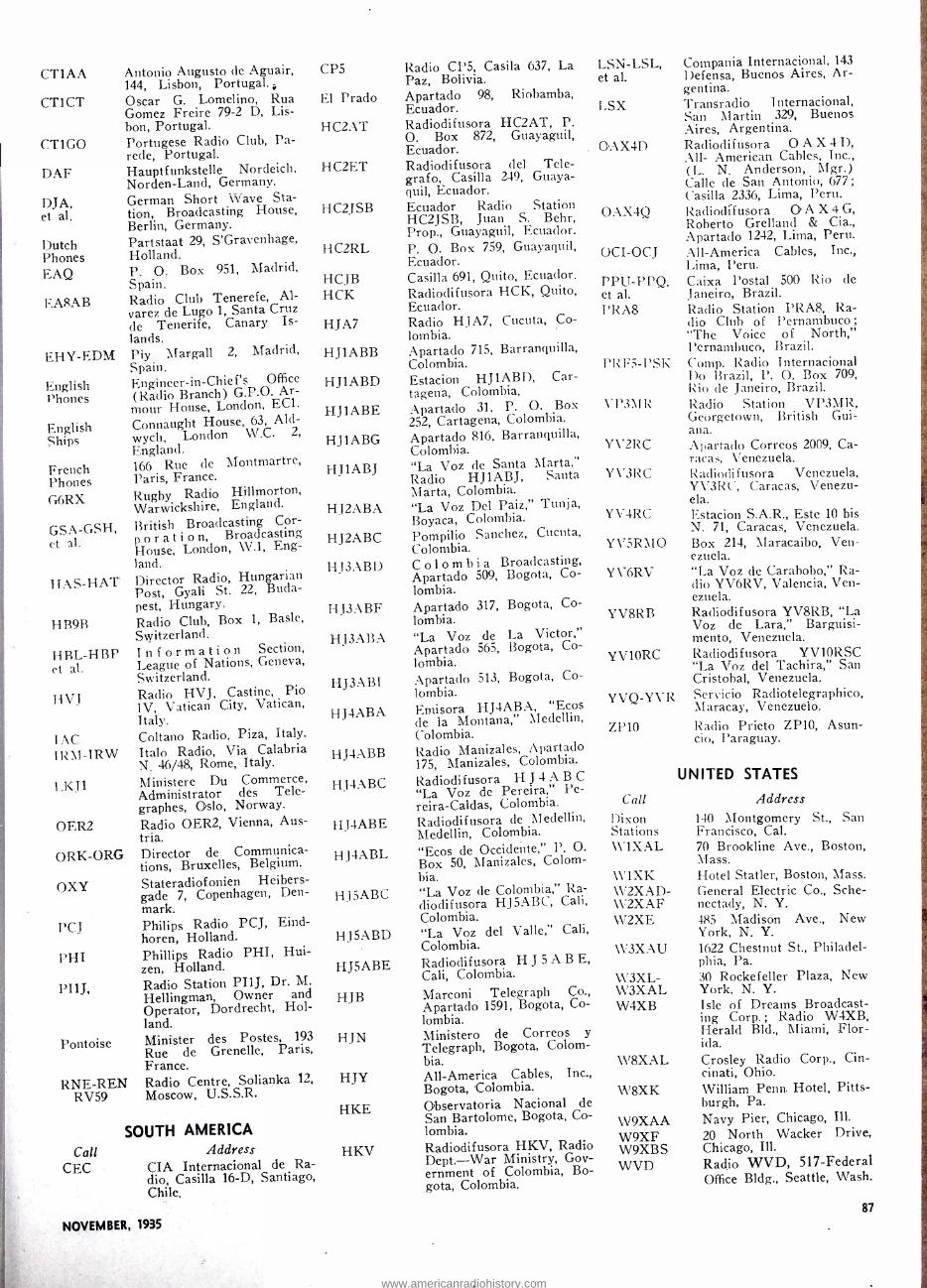
CT1AA
CT1CT
CT1GO
DAF
DJA, et al.
Dutch Phones EAQ
EA8AB
EHY-EDM
English Phones
English Ships
French Phones G6RX
GSA -GSH, et al.
HAS -HAT
HB9B
HBL-HBP et al.
HVJ
1AC Il:\I-IRW
1.KJ 1
OER2
ORK-ORG
OXY
Antonio Augusto de Aguair, 144, Lisbon, Portugal. Oscar G. Lomelino, Rua Gomez Freire 79 -2 D, Lis- bon, Portugal. Portugese Radio Club, Pa- rede, Portugal. Hauptfunkstelle Nordeich, Norden -Land, Germany. German Short Wave Sta- tion, Broadcasting House, Berlin, Germany. Partstaat 29, S'Gravenhage, Holland. P. O. Box 951, Madrid, Spain. Radio Club Tenerefe, Al- varez de Lugo 1, Santa Cruz de Tenerife, Canary Is- lands. Piy Margall Spain. Engineer -in- Chief's Office (Radio Branch) G.P.O. Ar- mour House, London, EC1.
Connaught House, 63, Ald- wych, London W.C. 2,
England. 166 Rue de Montmartre, Paris, France. Rugby Radio Hillmorton, Warwickshire, England.
British Broadcasting Cor- p o r a t i o n, Broadcasting House, London, W.1, Eng- land. Director Radio, Hungarian Post, Gyali St. 22, Buda- pest, Hungary. Radio Club, Box 1, Basle, Switzerland. Information Section, League of Nations, Geneva, Switzerland. Radio HVJ, Castine, Pio IV, Vatican City, Vatican, Italy. Coltano Radio, Piza, Italy.
Italo Radio, Via Calabria N. 46/48, Rome, Italy.
Ministere Du Commerce, Administrator des Tele- graphes, Oslo, Norway.
Radio OER2, Vienna, Aus- tria. Director de Communica- tions, Bruxelles, Belgium.
Stateradiofonien Heibers- gade 7, Copenhagen, Den- mark.
PCJ Philips Radio PCJ, Eind- horen, Holland. Phillips Radio PHI, Hui - zen, Holland. Radio Station PI1J, Dr. M. Hellingman, Owner and Operator, Dordrecht, Hol- land. Minister des Postes, 193
Rue de Grenelle, Paris, France. Radio Centre, Solianka 12,
Moscow, U.S.S.R.
2, Madrid,
PHI
PI1J,
Pontoise
RNE-REN RV59
Call CEC
SOUTH AMERICA Address
CIA Internacional de Ra- dio, Casilla 16 -D, Santiago, Chile.
NOVEMBER, 1935
CP5
El Prado
HC2AT
HC2ET
HC2JSB
HC2RL
HCJB HCK
HJA7
HJ1ABB
HJ1ABD
HJ1ABE
HJ1ABG
HJ1ABJ
HJ2ABA
HJ2ABC
HJ3ABD
H J3 ABF
HJ3ABA
HJ3ABI
HJ4ABA
HJ4ABB
HJ4ABC
HJ4ABE
Radio CP5, Casila 637, La Paz, Bolivia. Apartado 98, Riobamba, Ecuador. Radiodifusora HC2AT, P. O. Box 872, Guayaguil, Ecuador. Radiodifusora del Tele - grafo, Casilla 249, Guaya- quil, Ecuador. Ecuador Radio Station HC2JSB, Juan S. Behr, Prop., Guayaguil, Ecuador. P. O. Box 759, Guayaquil, Ecuador. Casilla 691, Quito, Ecuador. Radiodifusora HCK, Quito, Ecuador. Radio HJA7, Cucuta, Co- lombia. Apartado 715, Barranquilla, Colombia. Estacion HJ1ABD, Car- tagena, Colombia. Apartado 31, P. O. Box 252, Cartagena, Colombia. Apartado 816, Barranquilla, Colombia. "La Voz de Santa Marta," Radio HJ1ABJ, Santa Marta, Colombia. "La Voz Del Paiz," Tunja, Boyaca, Colombia. Pompilio Sanchez, Cucuta, Colombia. Colombia Broadcasting, Apartado 509, Bogota, Co- lombia. Apartado 317, Bogota, Co- lombia. "La Voz de La Victor," Apartado 565, Bogota, Co- lombia. Apartado 513, Bogota, Co- lombia. Emisora HJ4ABA, "Ecos de la Montana," Medellin, Colombia. Radio Manizales, Apartado 175, Manizales, Colombia.
Radiodifusora H J 4 A B C
"La Voz de Pereira," Pe- reira- Caldas, Colombia. Radiodifusora de Medellin, Medellin, Colombia.
HJ4ABL "Ecos de Occidente," P. O.
Box 50, Manizales, Colom- bia.
HJ5ABC "La Voz de Colombia," Ra- diodifusora HJ5ABC, Cali, Colombia.
HJ5ABD "La Voz del Valle," Cali, Colombia.
HJ5ABE Radiodifusora H J 5 A B E, Cali, Colombia.
HJB Marconi Telegraph Co., Apartado 1591, Bogota, Co- lombia. Ministero de Correos y
Telegraph, Bogota, Colom- bia. All- America Cables, Inc., Bogota, Colombia. Observatoria Nacional de San Bartolome, Bogota, Co- lombia. Radiodifusora HKV, Radio Dept. -War Ministry, Gov- ernment of Colombia, Bo- gota, Colombia.
HJN
HJY
EIKE
HKV
LSN-LSL, et al.
LSX
Compania Internacional, 143
Defensa, Buenos Aires, Ar- gentina. Transradio Internacional, San Martin 329, Buenos Aires, Argentina.
OAX4D Radiodifusora O A X 4 D, All- American Cables, Inc., (L. N. Anderson, Mgr.) Calle de San Antonio, 677; Casilla 2336, Lima, Peru.
OAX4Q Radiodifusora O. A X 4 G, Roberto Grelland & Apartado 1242, Lima, Peru.
OCI-OCJ All- America Cables, Inc., Lima, Peru.
PPU -PPQ, Caixa Postal 500 Rio de et al. Janeiro, Brazil. PRA8 Radio Station PRA8, Ra-
dio Club of Pernambuco ;
"The Voice of North," Pernambuco, Brazil. Comp. Radio Internacional Do Brazil, P. O. Box 709, Rio de Janeiro, Brazil. Radio Station VP3MR, Georgetown, British Gui- ana. Apartado Correos 2009, Ca- racas, Venezuela. Radiodifusora Venezuela, YV3RC, Caracas, Venezu- ela. Estacion S.A.R., Este 10 bis N. 71, Caracas, Venezuela. Box 214, Maracaibo, Ven- ezuela. "La Voz de Carabobo," Ra- dio YV6RV, Valencia, Ven- ezuela.
YV8RB Radiodifusora YV8RB, "La Voz de Lara," Barguisi- mento, Venezuela.
YV1ORC Radiodifusora YV1ORSC "La Voz del Tachira," San Cristobal, Venezuela.
YVQ -YVR
PRF5-PSK
\'P3\IR
YV2RC
Y\'3RC
YV4RC
YV5RMO
YV6RV
Servicio Radiotelegraphico, Maracay, Venezuelo.
ZP10 Radio Prieto ZP10, Asun- cio, Paraguay.
Call Dixon Stations \V'1XAL
\V1XK W2XAD- W 2XAF W2XE
W3XAU
W3XL- W3XAL W4XB
W8XAL
W8XK
W9XAA W9XF W9XBS WVD
UNITED STATES
Address 140 Montgomery St., San Francisco, Cal. 70 Brookline Ave., Boston, Mass. Hotel Statler, Boston, Mass. General Electric Co., Sche- nectady, N. Y. 485 Madison Ave., New York, N. Y. 1622 Chestnut St., Philadel- phia, Pa. 30 Rockefeller Plaza, New York, N. Y. Isle of Dreams Broadcast- ing Corp. ; Radio W4XB, Herald Bld., Miami, Flor- ida. Crosley Radio Corp., Cin- cinati, Ohio. William Penn. Hotel, Pitts- burgh, Pa. Navy Pier, Chicago, Ill.
20 North Wacker Drive, Chicago, Ill. Radio WVD, 517- Federal Office Bldg., Seattle, Wash.
87
www.americanradiohistory.com

SHORT -WAVE STATION LIST STAR BROADCASTERS INDICATED BY BOLD TYPE; PHONE (P) ; EXPERIMENTAL (E).
KC Meters Call 21540 13.92 W8XK 21530 1:3.9:3 CSJ 21500 13.95 NAA
21420 14.01 WKK
21160 14.19 LSL
21080 14.23 PSA
21060 14.25 KWN
21020 14.29 LSN
20860 14.38 EH Y
20860 14.38 ED NI
20380 14.72 GAA
20040 14.97 OPI.
20020 14.99 DHO
19980 15.02 KAX
19820 15.14 WKN
19720 15.21 EAQ
19680 15.24 CEC
19600 15.31 LSF
19530 15.36 EDR2
19530 15.36 EDS
19520 15.37 I R W
19500 15.40 LSQ
19355 15.50 FTM
19345 15.52 PMA
19260 15.58 PP], 19235 15.60 DFA
19220 15.61 WKF
19200 15.62 ORG
19140 15.68 LSM
18970 15.81 GAQ
18960 15.82 WQD
]8950 15.83 I13F
1^910 15.86 JVA
14890 15.88 ZSS
18860 15.91 WKM
18830 15.93 PLE
18740 16.01 PCP
18680 16.06 OCT
18620 16.11 GAU
18480 16.23 HBH
18440 16.25 HJY
18405 16.30 PCK
18350 16.35 FZS
18340 16.36 WLA
18310 16.38 GAS
18295 16.39 YVR
18250 16.43 FTO
18200 16.48 GAW
18190 16.49 JVB
Location Pittsburgh, Pa. Daventry, England Washington, D. C.
Lawrenceville, N. J.
Buenos Aires, Arg.
Itiu .le Janerio, Brazil
Dixon, Calif.
Buenos Aires, Arg.
:1ladrid, Spain
Madrid, Spain
Rugby, England
l.eopoldsville, Belg.
Nauen, Germany
9lanila, P. I.
Lawrenceville, N. J.
Madrid, Spain
Santiago, Chile
Buenos Aires, Arg.
Madrid, Spain
Madrid, Spain
Rome, Italy
Buenos Aires, Ár1;.
St. Assise, France
Bandoeng, Java
Rio de Janerio, Brazil
Nauen, Germany
Lawrenceville, N. J.
Brussells, Belgium
Buenos Aires, Arg.
Rugby, England
Rocky Point, N. Y.
Geneva. Switzerland
Nazaki, Japan
Klipkewvel, So. Africa l
Rocky Point, N. Y.
7imr 7 -9 1.N. (r -13 :4 i .1.111. (E) Time signals regu-
larly (P) Phones LSN -PSA
daytime (P) Phones GAA morn -
inzs; DFB. and EH 1" irregular
Phones WKK -WLK daytime
( P) Phones afternoon ir- regular
(P) Phones WKK -WLK daily; EIIY, FTM irregular
(P1 Phones LSM -PP (1- LSY mornings
(P) Phones LSM -PPU- I.SY mornings
Phones I.SL Tuortt- inrs: LSY -LSM -
PP[1 irregular Congo Africa Tests
with ORG morn- ings
(P) Phones I'PU -T.SM- YVR mornings
(P) Phones KWU eve -
nings (Pl Phones GAIT morn-
ings (P) Relays and tests in
A.M. (P) Phones OCT -IIJY
afternoons (P) Phones and tests ir-
regularly (P) Phones LSM -PPU-
YVR mornings (P) Phones I.SM -PPU-
l'VR mornings ( P) Phones I.SM -P.P[I
mornings ( P) Phones daytime ir-
regularly ( P ) Phones LSM -PPU-
YVR mornings (P) Phones PCK -PDK
early mornings (P) Phones DFB -EITY-
FTM mornings (P) Phones HSP -KAX
early mornings (P) Phones GAS -GA U
mornings (1') Phones OPT, morn-
ings (P) Phones DFB -FTM-
GAA-GAB morn- ings
(PI Phones ZSS morn- ings
( E) Tests !LSY irregu- larly
(E) Phones So. America mornings
(P) Phones and tests ir- regular
P) Phones GAO -GA [J mornings
(1 Tests and relays ir- regularly; Phones PCV mornings early
(P) KW LT evenings; music at times
(P) Relays and phones mornings irregular
(P) Phones CEC -HI \' days; \VKK -WOP noon
(P) Phones VWY -ZSS early A.M.: l.aw- renceville, da,-time
(E) Relays to N. Y. mornings irreg.
(P) Phones CEC -OCI noon; music at times
Phones PLE-PMC early A.M.
Phones FTK early mornings
Phones GAS morn- ins Phonges WLA -WMN
mornings Phones DFB -EHY-
FTM mornings Phones LSM -LSY-
mornings Relays and phones
N. Y. irreg. Phones Java early
mornings
(P)
( P)
(P)
Bandoeng, Java
Kootwijk, Holland
Lima, Peru
Rugby, England
Geneva, Switzerland
Bogota, Colombia
Kootwijk, Holland
Saigon, Indo -China
Lawrenceville, N. J.
Rugby, England
Maracay, Venezuela
St. Assise, France
Rugby, England
Nazaki, Japan
(P)
(P)
(P)
(P)
(P)
(P)
(P)
(P)
KC Meters Call 18170 16.51 CGA
18135 16.54 PMC 18115 16.56 LSY3 18040 16.63 GAB 17980 16.69 KQZ
17940 16.72 WQB 17900 16.76 WLL
17850 16.81 LSN 17830 16.82 PCV 17790 16.86 GSG
17780 16.87 W3XAL
17775 16.88 Pill
17760 16.119 DJE 17750 16.91 IAC
17740 16.91 HSP
17699 16.95 IAC
17545 17.10 VWY 17520 17.12 DFB
17480
17260
17120
17120
17080
16305
16300
17.16 VWY
17.37 DAF
17.52 WOO
17.52 WOY
17.56 GBC
18.39 PCL
18.44 WLK
16240 18.47 KGO
16214 18.50 FZR
16050 18.69 JVC
16030 18.71 KKP
15930 18.83 FYC
15880 18.89 FTK
15860 18.90 JVD
15860 18.90 CEC
15810 19.02 LSI.
15760 19.04 JYT
15740 19.06 JIA 15670 19.15 WAE 15660 19.16 JVE
15625 19.20 OCJ
15620 19.21 JVF 15595 19.24 DFR
15430 19.44 KWE 15415 19.46 KWO
15410 19.47 Prado 15370 19.52 1-14`
15355 19.54 KWU
15330 19.56 W2XAD
15280 19.63 DJQ 15270 19.64 W2XE 15260 19.66 (SI 15252 19.67 RIM 15243 19.68 15220 19.71 PCJ
Location Drummondville, Que. Bandoeng, Java Buenos Aires, Arg. Rugby, England Bolinas, Calif.
Rocky Point, N. Y.
Rocky Point, N. Y.
Buenos Aires, Arg. Kootwijk, Holland
Daventry, England
Bound Brook, N. J.
Ilittzen, Holland
Zeesen, Germany Piza, Italy
Itankok, Siam
Piza, Italy
Poona, India
Nauen, Germany
Poona, India
Nordenland, Germany
Ocean Gate, N. J.
Lawrenceville, N. J.
Rugby, England
Kootwijk, Holland
Lawrenceville, N.
Manila, P. I.
Saigon, Indo -China
Nazaki, Japan
J.
Kankuku, Hawaii
Pontoise, France
St. Assise, France
Nazaki, Japan
Santiago, Chile
Buenos Aires, Arg.
Kemikawa -Cho, Japan
Chureki, Japan
Brentwood, N. Y. Nazaki, Japan
Lima, Peru
Nazaki, Japan
Nauen, Germany
Bolinas, Calif.
Dixon, Calif.
Riobamba, Ecuador Budapest. Hungary Dixon, Calif.
Schenectady, N. Y.
Zeesen, Germany Wayne, N. J. Daventry, England Tashkent, U.S.S.R.
Pontoise, France Eindhoven, Holland
Time (P) Phones GBB morn-
ings (P) Phones PCK -PCV
early mornings (E) Phones DFD-FTM-
GAA-PPU A. M. (P) Phones LSM noon (E) Tests and relays to LSY irreg.
(E) Tests with LS mornings
(E) Relays to Geneva and Germany mornings
(P) Phones S. A. stations (P) Phones PLE early
mornings 6 -8:45 A.M. 9 :00 Á.M.-
1.2:00 noon 9 A.M. -1 P.M. daily ex- cept Sunday Mon. Thurs. Fri. 7 :30- 9:30 A.M. Sat. & Sun- day 7 :30 -10:00 A.M. 7:00 -11:30 A.M. (P) Phones and Tests to
ships A.M. (P) Phones DFA -DGH-
KAY early morn- ings
(P) Phones and tests to ships A.M.
(P) Phones GAU -GBC- GB'U mornings
(P) Phones PPU -YVR- KAY mornings
(P) Pitones GAU -GBC- GBU daytime
(P) Phones ships morn- ings
(P) Phones ships day- time
(P) ones England ir- reg.
(P) Phones ships d ay- time
(P) Special relays and phones irreg.
(P) Phones England ir-
(P) Phones JVE -KWU evenings
(P) Phones FTA -FKT early A.M.
(P) Phones Hong Kong early A.M.; Phones JVF -KGO- PLE early A.M. (P) KWU afternoons and evenings
(P) Phones 9:00 A.M. and irreg.
(P) FZR-FZS- LSM -PPU- YVR mornings
(P) Phones Shanghai early A.M.
(P) Phones OCJ morn- ings
(P) Phones GAA morn- ings
(E) Tests KKW -KWE KWU evenings
(P) Phones Nazaki early A.M.
(E) Tests afternoons (P) Phones PLE early
KTO eve -
nings. (P) Phones CEC day-
time (P) Phones KWO -KWU
after 4 P.M. (E) Tests and relays
mornings irreg. (P) Tests JYK -JYT-
s evenings (P) Phones JVF eve -
nings 5:00 -7:00 P.M. Sunday Sunday
nings
8 -9 A.M. (P) Phones Japan, Ma- nila and Java eve-
2.3 P.M. Weekdays -Sun- day 10:30 A.M. -4 P.M.
8 -11:40 A.M. 10 A.M. -5 P.M. 1 9 1 ç P.M. -4 P.M. (P) Phones RKI early
mornings 6-10 A.M. Sunday 7:30.10:00 A.M.
Tues. 3 -6 A.M. Wed. 7- 11 A.M.
ALL WAVE RADIO
www.americanradiohistory.com

KC Meters CsR 15220 19.71 W8KX 15200 19.74 DJB
15140 19.82 GSF
15121 19.84 HVJ 15055 19.92 WNC 15040 19.95 RKI
15040 19.95 HIR
14980 20.03 KAY
14940 20.06 HJB
14920 20.11 KQH 14845 20.19 OCJ2
14800 20.27 WQV
14710 20.39 IRG
14690 20.42 PSS
14653 20.47 GBL
14620 20.52 EHY
14620 20.52 EDM
14600 20.55 JVH
14600 20.55 J V I1
14590 20.56
14550 20.60
14530 20.65
14485 20.71
14485 20.71
14470 20.73
14440 20.78
14200 21.20
WMN
IIBJ
LSN
TIR
TIU
WMF
GBW
W%IOXFBe
14100 21.25 HJ5ABE
13900 21.58 WQP 13820 21.70 SUZ
13738 21.82 RIS
13690 21.91 KKZ
13667
13610 13585
13545
13415
13390
13345
13340
13285
13180
21.98
22.04 22.08
22.15
22.36
22.40
22.48
22.49
22.58
22.76
HJY
JYK CBB
PFG
GCJ
WMA
YVQ
KBJ
CGA3
DGG
13075 22.95 VPD
13000 23.08 FYC
12985 23.11 DFC
12865 23.32 TAC
12840 23.36 WOO 12830 23.37 HJC
12825 23.38 rNR 12825 23.38 CNR
1,2800 23.44 TAC
12780 23.47 GBC
12396 24.20 CT1GO
12394 24.21 DAN'
12300 24.39 VIM
12295 24.40 ZLU
1290 24.41 GBU
12280 24.43 KUV
NOVEMBER, 1935
Location Time Pittsburgh, Pa. 9 A.M. -7 P.M. Zeesen, Germany 3:45 -7:15 A.M.
8:00 -11:30 A.M. Daventry, England 6 -8:45 A.M. 9 A.M. -12
noon 4:15 -5:45 P.M. Vatican City, Vatican 10:30 -10:45 A.M. Hialeah, Fla. (P) Phones daytime Moscow, U.S.S.R. (P) Phones RIM early
A.M. Santo Domingo, R. D. (P) Phones WNC day-
time Manila, P. I. (P) Phones DFC -DFD-
GCJ early A.M.; KWU evenings
Bogota. Colombia (P) Phones WNC -PPI- YVQ days
Kahuku, Hawaii (P) Tests irregularly Lima, Peru (P) Phones HJY and
others daytime Rocky Point, N. Y. (E) Tests Europe ir-
reg. Nassua. Eritrea, Africa (P) Phones and tests
with JVH 5:00 to 7:00 A.M.
Rio de Janerio, Brazil (P) Phones LSL -WLK- WOK daytime
Rugby, England (P) Phones Nazaki, early A.M.
Madrid, Spain (P) Phones LSM morn- ings irreg.
Madrid. Spain (P) Phones PPU -PSA- PSE mornings
Nazaki, Japan (E) Phones DFB -GTJ- PCJ -TYB early mornings and B.C. music
12 A.M. -1 A.M. Daily; 4 -5 P.M. Mon. and Tues.
(P) Phones England day- time
(E) Relays to Riverhead daytime
(P) Phones PSF -WLK- WOK irreg.
(P) Phones WNC day- time
(P) Phones WNC clay - time
(P) Phones England daytime
(P) Phones Lawrence- ville daytime
(E) Irregular
:Nerzaki, Japan
Lawrenceville, N. J.
Geneva, Switzerland
Buenos Aires, Arg.
Cartago, Costa Rica
Cartago, Costa Rica
Lawrenceville, N. J.
Rugby, England
The Schooner "Morrissey"
Medillin, Colombia
Rocky Point, N. Y. Cairo, Egypt
Tiflis. U.S.S.R.
Bolinas. Calif.
11:00 A.M. -12 noon daily ex. Sun. 6:00 -10:30 P.M.
(E) Test daytime (P) Phones DFC -DGU-
GBB daytime (P) Tests with Moscow
irregular (F) Tests Japan and
Java early A.M.; days Honolulu
Bogota. Colombia (P) Phones ECE after- noons
Kemikawa -Cho, Japan (E) Tests irregular A.M. Rugby, England (P) Phones CGA3 -SUV-
SUZ daytime Kootwijk, Holland (P) Tests mornings ir-
regular Rugby, England (P) Tests with JVH af-
ternoons Lawrenceville, N. J. (P) Phones GAS -GBS-
GBU -GBW daily Maracay, Venezuela (P) Phones WNC -HJB
days Manila, P. I. (P) Phones nights and
early A.M. Drummondville, Que. (P) Phones England
days Nauen, Germany (P) Relays to Riverhead
days Suva, Fiji Islands Mon. to Sat. 12 :30.1 :30
A.M. Paris, France (P) Phones CNR morn-
ings Nauen, Germany (P) Phones KAY -SUV-
SUZ early A. M. Piza, Italy (P) Phones ships irregu-
lar Ocean Gate. N. J. (P) Phones ships days Barranquilla, Cólombia (P) Phones HJB-HPF-
WNC days Rabat, Morocco Sunday 7:30 -9:00 A.M. Rabat, Morocco (P) Phones FYB -TYB-
FTA irreg. Piza, Italy (P) Phones ships and
tests Tripoli, ir- reg.
Rugby, England (P) Phones VWY early A.M.
Parede. Portugal Sun. 11 :30 A.M. -1 P.M.; 7:15 -8:30 P.M. Tues. to Fri. 7:15 -8:30 P.M.
Nordenland, Germany (P) Phones ships irreg. mornings
Bandoeng, Java (P) Phones 2ME near 6:30 A.M.
Willmigton, N. Z. (P) Phones JLJ early A.M.
Rugby, England (P) Phones Lawrence- ville days
Manila, P. I. (P) Phones early A.M.
KC Meters Cal! 12250 24.49 TYB
12240 24.51
12220 24.55
12215 24.56
12060 24.88
12035 24.93
12020 24.95
12010 24.97
TFJ FLJ TYA
PDV
IIBO
VIY
CJA6
12000 25.00 RNE
11991 25.02 FZS
11950 25.11 KKQ
11940 25.13 FTA
11935 25.14 YNA
11885 25.23
11870 25.26 W8XK 11860 25.29 GSE 11830 25.36 W2XE 11811 25.40 2R0
11800 25.42 CO9WR 11790 25.43 W1XAL
11770 2549 DJD
11750 25.53 GSD
11720 25.60 CJRX
11713 25.62
11710 25.63 HJ4ABA
11680 25.68 KIO
11670 25.71 PPQ
11660 25.73 IVI.
11570 25.93 HH2T 11538 26.00 XGR 11500 26.09 XAM
11495 26.10 VIZ3
11405 26.26 CJA4
11385 26.35 HBO
11275 26.61 ZAM
11000 27.27 ZLT
11000 27.27 PLP
10975 27.35 OCI
10975 27.35 OCP
10910 27.50 KTR
10850 27.63 DFL
10840 27.68 KWV
10790 27.80 YNA
10770 27.86 GBP
10740 27.93 JVM 10675 28.10 WNB 10670 28.12 CEC
10670 28.12 CEC
10660 28.14 JVN
10660 :28.1-1 JVN
Location Paris, France
Reykjavik, Iceland Paris, France Paris, France
Kootwijk, Holland
Geneva, Switzerland
Rockbank, Australia
Drummondville, Que.
Moscow, U.S.S.R
Saigon. Indo -China
Bolinas Calif.
St. Assise, France
Managua Nicaragua
Pontoise, France
Pittsburgh, Pa. Daventry, England Wayne, N. J. Rome, Italy
Sancti -Spiritus, Cuba Boston, Mass.
Zeesen, Germany
Daventry, England
Winnipeg, Manitoba
Pontoise, France
Medillin, Colombia
Kaukuku, Hawaii
Rio de Janerio, Brazil
Nazaki, Japan
Port -au- Prince, Haiti Shanghai. China Merida, Mexico
Rockbank, Australia
Drummondville, Que.
Geneva, Switzerland
Merida, Mexico
Wellington, N. Z.
Bandoeng, Java
Lima, Peru
Lima, Peru
Manila, P. I.
Nauen, Germany
Dixon, Calif.
Managua, Nicaragua
Rugby, England
Nazaki, Japan Lawrenceville, N. J. Santiago, Chile
Santiago, Chile
Nazaki, Japan
Nazaki. Japan
Time' (P) Phones JVII -XGR.
and ships irreg. (P) Phones England days (P) Phones ships irreg. (P) Algeria, days- -- "In-
verted Speech" (P) PLE - PLV - PMC
early mornings (E) Relays programs &
phones irreg. (P) Tests CJA6 early
A.M. and evenings (P) Tests VIY early
A.M. and evenings Daily 3 -6 P.M. Wed. 6 -7
A.M. Sun. 6 -7 A.M. 10- 11 A.M.
(P) Phones FTA -F'l'K early A.M.
(P) Relays programs to I- Iawaii eve.
(P) Phones FZS -FZR early A.M.
(P) Cent. and S. A. stations, days
10:15 A.M. -1 :15 P.M. 2-5 P. M.
5 -9 P.M. 9 A.M. -12 noon 5 -7 P.M. 8:15 -9 A.M. 9:15 -10:15
A.M. 12 noon -1 P.M.- 1:45-5 P.M.
4 -6:30 P.M. 9 -11 P.M. Tues. and Thurs. 6 -9 P.M.
Sunday 5 -7 P.M. 12 noon -4 :30 P.M. -5 :05-
10:45 P.M. 1:15.3:20 A.M. 12:15 -4
P.M. 4 :15-5 :45 P.M. 6:00 -8:05 P.M. 10- 11 :05 P.M.
Week days 7 :30 P.M.-11 midnight; Sunday 3 -10 P.M.
3-4 A.M. -6 -9 P.M. 10 P.M. -12 A.M.
11 :30 A.M. -1 P.M. 6- 10:30 P.M.
(P)
(P)
(P)
Phones early
Phones LSX
Phones
Far -East A.M. WCG-W ET-
evenings Taiwan eve-
pings (P) Evenings -irregular (P') Tests irregularly (P) Phones XDF -XDM-
XDR irreg. (P) Tests CJA4 early
A.M. (P) Phones VIZ3 early
A.M. (E) Phones and relays
irregular (P) Phones XDR -XDM
irregular (P) Phones VLZ early
mornings (P) Phones early A.M.;
broadcasts 10 -10:30 A.M.
(P)
(P)
(P)
(P)
(P)
Phones CEC -HJY days
Phones HKB early evenings
Phones DFC early A.M. irreg.
Relays programs af- ternoons irreg.
Phones Japan. Ma- nila, Hawaii. morn- ings
(P) Phones So. America days, irreg.
(P) JYS and XGR ir- reg.; Phones VLK early A.M. and eve.
4-7 :30 A.M. irregular (P) Phones ZFB daytime (P) Phones H.JY -OCI
daytime 8 :30-9 :00 P.M. Thurs.
and Sun. (P) Phones JIB early
A.M.: Relays JOAK irreg.
4 -7:30 A.M. Irregular
www.americanradiohistory.com

KC Meters Call Location Time 10630 28.22 WED Rocky Point. N. 1.. Relays program service ir-
reg. 10620 28.25 EHX Madrid, Spain (P) Phones CEC and
EHZ afternoons 10610 28.28 WEA Rocky Point, N. Y. (E) Tests Europe irreg. 10550 28.44 WOK Lawrenceville, N. J. (P) Phones LSN -PSF-
PSH-PSK eve- nings
10535 28.48 JIB Tawian, Japan (P) Phones JBL -JVN early mornings
10520 28.52 VK2ME Sydney, Australia (P) Phones GBP -HVJ early A.M.
10520 28.52 VLK Sydney, Australia (P) Phones GBP -HVJ early A.M.
10440 28.74 DG II Nauen, Germany (P) Phones HSG -HSJ- HSP early A.M.
10430 28.80 YBG Medan, Sumatra (P) Phones PLV -P'LP early A.M.
10420 28.79 XGR Shanghai, China (P) Tests GBP-KAY early A.M.
10420 28.79 PDK Kootwijk, Holland (P) Phones PLV A.M. and special pro- grams irreg.
10410 28.82 KES Bolinas, Calif. (P) Phones S. A. and Far East irreg.
10400 28.85 KEZ Bolinas, Calif. (P) Phones Hawaii and Far East irreg.
10380 28.90 WCG Rocky Point, N. Y. (E) Special program serv- ice irreg.
10375 28.92 JVO Nazaki, Japan (P) Manchuria and Dairen early A.M.
10370 28.93 l:l I L Madrid, Spain (P) Phones Elf day- time
10350 28.98 I.SX Buenos Aires. Arg. Near 10 P.M. irregular. 6- 7:15 P.M. daily
( P) Phones afternoons 1:30 -3:00 P.M. (P) Tests New York and
Buenos Aires eve- nings.
(P) Phones GCA -HJY- PSH afternoons
( P) Phones GCA -H.TY- PSH afternoons
(E) Phone and pgm. service irreg.
Zeesen. Germany l'sed irregularly. Panama City, Panama ( P) Phones C. A. and
S. Am. daytime Bandoeng, Java (P) Tests VLSI early
A.M. Buenos Aires, Arg. (P) "Inverted Speech"
afternoons Rio de Tanerio, Brazil (PI Phones I.SL -WOK
evenings ; special pgm. service irreg.
(P) Phones RIR -RNE early A.M.
(I') Phones DGH early A.M. irreg.
Leopoldsville, Belg -Congo (P) Phones OPK after- noons
Leopoldsville. llelg -Congo Occasional S a t u r d a y s 3:30 -4:10 P.M.
(P) Phones RIO -RNE early A.M.
Phones YVR after- noons
Phones WNB day- time
Phones DFC -DGU- GCA and GCB. daytime
Barranquilla, Colombia (P) Tests early eve- nings irreg.
(P) Phones JVQ -KWX- PLV early A.M.
(P) Tests irregularly (P) Phones WNA eve -
nings (P) Phones CEC-OCP
PSH -PSK after- noons
(P) Phones LSO after- noons
(P) Phones WOK -WLK evenings and nights
4 -7 A.M. irregular Saturday 1 -3 P.M. Daily
5:15 -7 P.M. often to 9 :30 P.M.
Kenukawa -Cho, Japan (1E) Tests irregular Rome, Italy
10335 29.03 ZED 10330 29.01 ORK 10310 29.10 PPM
10300 29.13 T.SQ
10300 29.13 LST.
10290 29.15 DIQ
10290 29.15 DIO 10290 29.15 HPC
10260 29.24 PMN
10250 29.27 LSK3
10220 29.35 PSI!
111170 29.50 RIO
10169 29.50 USC
10140 29.59 OPM
10140 29.59 OPM
10080 29.76 RI R
10070 29.79 ETI1'
10055 29.84 ZFB
10055 29.84 SUV
10040 29.88 HJA3
9990 30.01 KAZ
9966 30.08 IRS 9950 30.13 GBU
9930 30.21 HKB
9930 30.21 HJY
9890 30.33 LSN
9870 30.40 JYS 9860 30.43 EAQ
9840 30.47 JYS 9830 30.50 IRM
Iamilton, Bermuda Brussels, Belgium Rio de Janerio, Brazil
Buenos Aires, Arg.
Buenos Aires, Arg.
Zeesen, Germany
Bakou, U.S.S.R.
Bankok, Siam
Tiflis, U.S.S.R.
Madrid, Spain
Hamilton, Bermuda
Cairo, Egypt
(P)
(P)
(P)
Manila, P. I.
Rome, Italy Rugby, England
Bogota, Colombia
Bogota, Colombia
Buenos Aires, Arg.
Kennkawa -Cho, Japan Madrid, Spain
9810 30.58 DFE Nauen, Germany
9800 30.59 GCW Rugby, England
90
(P) Phones JVP -JZT- LSX -WEL morn- ings
(P) Relays and tests afternoons irreg.
(P) Phones Lawrence- ville eve. and nights
KC Meters C all 9800 30.59 LSI 9760 30.74 VI.J
9760 30.74 VLZ
9750 30.77 WOF 9710 30.88 GCA
9700 30.93 LOA
9635 31.13 2R0
9620 31.17 DGU
9620 31.17 FZR
9600 31.25 CT1AA
9595 31.27 HBL 9590 31.28 W3XAU
9590 31.28 VK2ME
9590
9580
9580
31.28 HPSJ
31.31 GSC
31.31 VK3LR
9570 31.34 LKJ1 9570 31.33 WIXK
9565 31.36 VUT
9560 31.38 DJA
9540 31.45 DJN
Location Buenos Aires, Arg. Sydney. Australia
Sydney, Australia
Lawrenceville, N. J. Rugby, England
Buenos Aires, Arg.
Rome, Italy
Nauen, Germany
Saigon, Indo -China
Lisbon, Portugal
Geneva, Switzerland Philadelphia, Pa.
Sydney, Australia
Panama City, Panama
Daventry, England
Melbourne, Australia
Jeloy, Norway Boston, Mass.
Bombay, India
Zeesen, Germany
Zeesen, Germany
9530 31.48 W2XAF Schenectady, N. Y.
9510 31.55 GSB
9510 31.55 VK3ME
9501 31.56 PRFS
9480 31.65 PLW
94.80 31.65 KET
9470 31.68 WET
9460 31.71
9430 31.80 YVR 9428 31.81 COCII
e 9415 31.86 PLV
9400 31.92 XDR
9330 32.15 CGA4
9280 32.33 GCB
9180 32.68 ZSR
9170 32.72 WNA
9147 32.79 YVR
9120 32.88 HATO 9110 32.93 KUW
9020 33.26 GCS
9010 33.30 KEJ
8975 33.43 VWY
8950 33.52 WEL
8950 33.52 W2XI3J 8900 33.71 ZLS
Daventry. England
Melbourne. Australia
Rio De Janeiro. Brazil
Bandoeng, Java
Bolinas, Calif.
Rocky Point, N. Y.
Tripoli, Africa
Maracay, Venezuela Havana. Cuba
Bandoeng, Java
Mexico City, Mexico
Drummondville, Que.
Rugby, England
Kliphewvel, S. Africa
Lawrenceville, N. J.
Maracay, Venezuela
Budapest. Hungary Manila, P. I.
Rugby, England
Bolinas. Calif.
Poona, Ind.
Rocky Point, N. Y.
Rocky Point, N. Y. Wellington, N. Z.
8830 33.98 LSD Buenos Aires, Arg.
Time (P) Rela' s very irreg. (P) Phones PLV -ZLT
early A.M. (P) Phones PLV -ZLT
early A.M. (P) Phones GCU irreg. (P) Phones LSL after-
noons (P) Tests and relays
early evening Mon. Wed. Fri. 6.9:00
A.M. (P) Phones SUV A.M.
Tests and relays irreg.
(P) Phones Paris early A.M.
Tues. Thurs. Sat. 4 :30 -7 P.M.
Saturday 5 :30 -6 :15 P.M. 11 A.M. -7 P.M.
12 :30-2 :30 A.M. Sundays 4 :30-8 :30 A.M.
9:30 -11 :30 A.M.
11 :45 A.M. -1 P.M. 7 :30- 10 P.M.
4:15 -5:45 P.M. 6 -8:05 P.M. 10 -11:05 P.M.
Mon. Tues. Wed. Thurs. 3:15 -7:30 A.M. Fri. 10:30 P.M. -2 A.M. Sat. 5 -7:30 A.M.
5 -8 A.M. 10 A.M -6 P.M. Week days 6 A.M. -12 mid-
night Sunday 7 A.M. -12 midnight
11:30 A.M. -12:30 P.M. Wed. & Sat. Sunday 7:30.8:30 A.M.
12:30 -2:15 A.M. 8.11:30 A.M. 5:05 -9:15 P.M.
12:30 -2:15 A.M. 3:45- 7:15 A.M. 5:05 -10:45 P.M.
Week days 6:30 P.M. -12 A.M. Sundays 4 :15 P.M. -12 A.M.
1:15 -3:20 A.M. 9 A.M -12 noon 12:15 -4 P.M. 4:15 -5:45 P.M. 6:00- 8:05 P.M.
Wed. to Sat. Inc. 5 -7 A.M.
-1:45 -5:45 P.M. daily 9. 10:45 P.M. irreg.
(P) Phones Australia early A.M.
(P) Phones WEL eve- nings & nights
(E) Tests LSX -PPM- ZFD evenings
(P) Phones Italy morn- ings.
(P) Tests mornings 10 A.M. -12 noon. 4 :00-
6:30 P.M. 8:00 -10:00 P.M.
(P) Phones PCV -PCK- PDK -VLZ -KWX and KWV early mornings
(P) Phones XAM irreg. days
(P) Phones GCB -GDB- GBB afternoons
(P) Phones Canada af- ternoons
((P) Phones Rugby af- ternoons seasonally
(P) Phones GBS -GCU- GCS afternoons
(P) Phones EHY after- noons
6 :00.7:00 P.M. Sundays (P) Tests and phones
early A.M. (P) Phones Lawrence-
ville afternoons (P) Relays programs to
Hawaii eve. (P) Phones GBC -GBU
mornings (E) Tests with Europe
irreg. (E) Tests irregularly (P) Phones VLZ early
mornings (P) Relays to N. Y
early evenings
ALL WAVE RADIO
www.americanradiohistory.com

KC Meters Call 8790 34.13 HRV
8790 34.13 TIR
8790 34.13 HKV
8775 34.19 PNI
8760 34.35 GCQ
8750 34.29 ZBW
8740 34.35 WXV 8730 34.36 GCI
8680 34.56 GBC
8665 34.62 CO9JQ
8650 34.68 WVD 8560 35.05 WOO
8470 35.39 DAF
8404 35.69 HC2AT
8380 35.80 IAC
8214 36.50 HCJB
8185 36.65 PSK
8140 36.86 LSC
8120 36.95 KTP
8110 37.00 ZP1O 8035 37.33 CNR 7970 37.64 XGL 7968 37.65 HSJ
7960 37.69 VLZ
7920 37.88 GCP 7900 37.97 LSL
7880 38.05 JYR
7860 38.17 SIX
7855 38.19 LQP 7797 38.47 HBP 7790 38.49 YNA
Location Bogota, Colombia
Cartago, Costa Rica
Bogota, Colombia Makasser, D. E. I.
Rugby, England
Hong Kong. China
Fairbanks, Alaska Rugby, England
Rugby, England
Camagney. Cuba
Seattle, Wash. Ocean Gate, N. J.
Nordenland, Germany
Guayaguil. Ecuador
Piza, Italy
Quito, Ecuador
Rio de Janerio, Brazil
Buenos Aires, Arg.
Manila, P. I.
Ascunsion. Paraguay Rabat, Morocco Shanghai, China Bankok, Siam
Sydney, Australia
Rugby, England Buenos Aires, Arg.
Kemikawa -Cho, Japan
Cairo, Egypt
Buenos Aires, Arg. Geneva, Switzerland Managna, Nicaragua
7790 3839 FFC2JSB Guayaguil, Ecuador
7780 38.56 PSZ
7765 38.63 PDM
7715 38.89 KEE
7669 39.11 Tt:F
7626 39.31 RIM
7610 39.42 KWX
7565 39.66 KWY
7520 39.89 KKH
7518 39.90 RKI
7510 39.95 JVP.
7470 40.16 JVQ
7470 40.16 HJP
7445 40.30 HBQ
7430 40.38 ZLR
7400 40.54 WEM
7390 40.55 HJ3ABD
7385 40.62 OEK
7380 40.65 XECR
7370 40.71 KEQ
NOVEMBER, 1935
Rio de Janerio, Brazil
Kootwijk, Holland
Bolinas, Calif.
Guatemala City. Guate- mala
Tashkent, U.S.S.R.
Dixon, Calif.
Dixon, Calif.
Kanhuku, Hawaii
Moscow, U.S.S.R.
Nazaki, Japan
Nazaki, Japan
Bogota, Colombia
Geneva, Switzerland
Wellington, N. Z.
Rocky Point, N. Y.
Bogota, Colombia
Wein, Austria
Mexico City, Mexico
Kankuku, Hawaii
Time KC Meters Call Location (E) Tests early evenings 7280 41.20 HJ1ABD Cartagena, Colombia
and nights (P) Phones Central
America daytime 7210 41.60 EA8AB 6:00 -11 :00 P.M. irregul - 7177 41.80 CR6AA (P) Phones PLV early
mornings 7118 42.13 HB9B (P) Phones ZSR after-
noons 7100 42.25 HKE 4:00 -10:00 A.M. 11:311
P.M. -1:15 A.M. 7080 42.37 PI1J (P) Phones WXH nights (P) Phones VWY after- 7080 12.37 VP3MB
noons (P) Phones ships and
New York daily 11:30 A.M. -12:30 P.M.
8:00 -9:09 P.M. (P) Tests irregularly (P) Phones ships day-
time (P) Phones ships irregu-
larly 8:00 -11:00 P.M. ex. Sun-
day (P) Phones ships irregu-
larly 12:30 -2:15 P.M. 7:15-
11:15 P.M. daily ex. Monday
(P) Phones LSL -WOK evenings and spe- cial programs
(P) Tests evenings and nights irreg.
(P) Phones KWX -KWV- PLV-JVQ morn- ings
8:00 -10:00 P.M. Sunday 2:00 -5:00 P.M. (P) Tests early mornings (P) Tests and phones
early A.M. (P) Phones ZLT early
A.M. (P) Phones VLK irreg. (P) Phones PSK -PSH
evenings (E) Tests and relays ir-
regularly (P) Phones GCB after-
noons (P) Tests evening irreg. 5 :30 -6 :15 P.M. Saturdv- (P) Phones Cent. & So.
America daytime 9:15 A.M. -2 :15 P.M.
7:15 -11:15 P.M. (P) Tests LSX early
evenings (P) Special relays to
Dutch Indies (P) Relays programs to 6520 46.01 YV6RV Valencia, Venezuela
Hawaii seasonally (P) Phones TIU -HPF
daytime 6503 46.10 HIL (P) Phones RKI early
mornings (P) Phones KKH nights;
KAZ - KTP - PLV- JVT-JVM morn- 6447 46.51 tugs
(P) Phones Shanghai, early mornings 6425 46.69 VE9AS Fredericton, N.B.
(P) Tests KEE evenings; Phones KWX - 6425 46.69 W9XBS Chicago, III. KWV nights
(P) Phones RIM early mornings 6420 46.70 W3XL Bound Brook, N. J.
Tests Point Reyes early A.M. 6415 46.77 HJA3
(P) Relays and phones early A. M. 6400 46.88 YNIGG Managua, Nicaragua
(P) Phones HJA3 -YVQ early evenings
(E) Relays Special B.C. evenings irreg.
(P) Phones VLJ early mornings
(E) Special relays eve- nings.
12 noon -2 P.M. 8:00- 11 :00 P.M.
(P) Tests early evenings very irreg.
Sundays 6 -7 P.M. Occa- sionally later
(P) Relays nings
programs eve-
6990 42.92 JVS
6935 43.25 WEB
6905 43.45 GLS
6900 43.48 I-1I3C
6860 43.73 KEL
6840 43.86 KEN 6811 4 -1.12 H1H
6755 44.41 WOA
6750 44.44 JVT
6750 44.44 JVT 6740 44.51 WEJ
6733 44.53 WDA 6725 44.60 WQO 6720 -11.96 YVQ 6701 44.71 'FIEP 6680 44.91 DGK
6672 44.96 YVQ
6650 45.11 IAC
6635 45.00 HC2RL Guayaguil, Ecuador
Time II :15 A. \1. -1 :15 P
Sunda y. Weekday-. 7:15 -9:15 P.M.
Santa Cruz, Canary Is. 5 -7:30 P.M. irregular Labito, Angela, Africa 2 :30-4 :30 P.M. Wed. &
Sat.
Basle, Switzerland Mon.. Flturs.. Fri. 4 -6 P.M.
Bogota, Colombia Monday 6 -7 P.M. Tues. and Friday 8 -9 P.M.
Dordrecht, Holland Saturday 10:10 -11:10
Georgetown, Br. Guiana Sun 7 :15 -10:15 A.M. Mon 3 15 -4 :45 P.M. 6 -15 -7 :15 P.M. Wed. Thurs. Sat. 5 -7 :45 P.M.
Nazaki, Japan (P) Phones China morn- ings early
Rocky Point, N. Y. (E) Relays programs eve- nings
Rugby, England (P) Phones WOA -WNA- \VGN evenings
LaRomana, R. D. Daily 12:15 -2 P.M. 6- 7:30 P.M. Sat. 12 mid- night-2 :00 A.M.
Bolinas, Calif. (P) Tests KAZ -PLV early A.M.
Bolinas, Calif. (P) Used irregularly San Pedro de Macoris,R.D.Sunday 3 -4 A.M. 12:30-
2 P.M. 4 -6 P.M. Mon. to Sat. inc. 12 :30-2 P.M. 7 -9 P.M.
(P) Phones GDW -GDS- GCS evenings
(P) Phones JOAK irregu lar; Phones Point Reyes at times
Nazaki, Japan 2 :00-8 :00 A.M. irregular Rocky Point, N. Y. (E) Commercial program
service evenings Rocky Point, N. Y. (E) Tests evenings irreg. Rocky Point, N. Y. (E) Tests evenings irreg. Maracay, Venezuela 8 :00-9 :00 P.M. Saturdays San Jose. Costa Rica 7:00 -10:00 P.M. daily Nauen, Germany (P) Relays to Riverhead
evenings irreg. Maracay, Venezuela (P) Phones and relays
N. Y. evenings I'iza, Italy (P) Phones ships irregu-
larly 5:45 -7:45 P.M. Sunday.
9:15 -11:15 P.M. Tues- day
Riobamba, Ecuador Thursday 9:00 -11 :15 P.M. Moscow, U.S.S.R. 1 :00-5 :00 P.M. irregular Santo Domingo. R.D. 12:15 -2:00 P.M. 5:00-
8:00 P.M. except Sun- day
San Jose, Costa Rica Sunday 11:00 A.M.-1 :00 P.M. 6:00 -7:00 P.M. 8 :00-9 :00 P.M. Week- days 6:00 -9:00 P.M. and later
11:30 A.M. -12:30 P.M. 5:30 -10:00 P.M. ex- cept Sunday
Santo Domingo, R.D. Mon. to Sat. inc. 12:15- 1:45 P.M. Sat. 7:45- 9:45 P.M.
7 :00-10 :00 P.M. ex. Sun- day
HJ1ABB Barranquilla, Colombia 11 :45 A.M.-1 :00 P.M. 5:30 -10:00 P.M. ex. Sunday
Occasional broadcasts - not regular
Not regular. Usually Tuesday and Thursday 1:00 -5:00 P.M.
No regular schedule main- tained
Barranquilla, Colombia (P) Phones HJA2 eve- nings
Daily 1 :00-2 :30 P.M. 7:00 -10 :00 P.M.
San Jose, Costa Rica 8:30 -11:00 P.M. Caracas, Venezuela 4:30 -10:30 P.M. Nazaki, Japan 5:00 -7:00 A.M. irregular Santo Domingo. R.D. 4:45.5:45 P.M. daily.
10:45 P.M:12:45 A.M. Sat.
(P) Phones afternoons 7 :00-11 :30 P.M. ex. Sun-
day Parede. Portugal Sunday 11 :30-1 :00 P.M.
7:15 -8:30 P.M. Tues. to Fri. inc. 7:15- 8:30 P.M.
Santiago de Caballeros. 11 :45 A.M.-1 :45 P.M. R.D. 7:45 -9:45 P.M. ex Sun-
day
Lawrenceville, N. J.
Nazaki, Japan
6620 45.31 Prado 6610 45.38 REN 6590 45.50 HI4D
6550 45.81 TIRCC
6490 46.30 HJ5ABD Cali. Colombia
6385 46.99 TI2GP 6375 47.10 YV4RC 6350 47.39 JZG 6315 47.50 HIZ
6235 48.10 OCM Lima, Peru 6230 48.00 OAX4G Limp, Peru
6198 48.40 CT1GO
6185 48.50 HI1A
91
www.americanradiohistory.com

AC Meters Call '6170 48.62 11J3ABF
6165 48.66 YV3RC
6150 48.78 11J5ABC
-6150 48.78 IIJ2AB.3.
6150 48.78 CJRO
6150 48.78 CQ9GC
'6150 48.78 CSL
6140 48.86 W8XK 6130 48 .92 ZGE
6130 48.92 COC D
6130 48.92 LKJ1
6120 49.02 W2XE 6120 49.02 YHA
6115 4').06 IUJIADE
Location Bogota, Colombia
Caracas, Venezuela
Cali, Colombia
Tunja, Colombia
Winnipeg, Manitoba
Santiago, Cuba
Lisbon, Portugal
Pittsburgh, Pa. Kuala Lam pur, S.S.
Havana. Cuba
Jeloy, Norway
Wayne, N. J. Bandoeng, Java
Cartagena, Colombia
Time 6:00 -11:00 P.M. ex. Sun-
day 10:30 A.M. -1:30 P.M.
4:30 -10:00 P.M. ex- cept Sunday
Daily 11 :00 AM. -12 noon; 7:00 P.M. -10:00 P.M.
1 :00-2 :00 P.M. & 7:00- 10:00 P.M.
Weekdays 7:30 P.M. -12 noon. Sundays 3:00- 10:00 P.M.
12:00 A.M. Sat. -2:00 A.M. Sunday
7:30 -8:30 A.M. 2:30- 7:00 P.M.
9 :00 P.M. -1:00 AM. daily Sun. Tues. Fri. 6 :40 -8 :40
A.M. Sunday 12:00 -2:00 P.M.
8:00 -10:30 Y.M. Week- days 11:30 A.M. 4:00 P.M. 6:00 P.M. -12 A.M.
10:00 A.M. -6:00 P.M. daily
7:00 -10:00 P.M. daily 5:30 -11:00 P.M. 5:45-
6:45 P.M. 10:30 P.M.- 1 A.M.
Sun. 10 A.M. -2 P.M. Mon. 7 :30 -9 :.,0 P.M. Mon.
KC Meters Coll 6010 49.92 ZHI
6010 49.92 COCO
6006 49.95 HJIABJ 6005 49.96 VE9DR 6005 49.96 VE9DN 6000 50.00 XEBT
5980 50.17 HIX
5980 50.17 XECW
5969 50.26 HVJ 5960 50.30 YNLF 5930 50.60 11J4ABE
5900 50.85 HJ2ABC
5900 50.85 HCK 5890 50.93 TGX
(TG2X) 5880 51.02 YV8RB 5853 51.20 WOB
5850 51.28 YV5RMO
Locution Singapore, S.S.
Havana, Cuba
Santa Marta, Colombia Montreal, Que. Montreal, Que. Mexico City, Mexico
Santo Domingo, R.D.
Mexico City, Mexico
Vatican City, Vatican Managua, Nicaragua Medillin, Colombia
Cucuta, Colombia
Quito, Ecuador Guatemala City, Guate-
mala Barguisimeto, Venezuela Lawrenceville, N. J.
Maracaibo, Venezuela
6112 4.9.118 YV_it1; Caracas, Venezuela
6110 49.10 IIJ4ABB Manizales, Colombia
6110 49.10 VUC
6110 49.10 VE9HX
6110 49.10 GSr.
6100 49.18 W9XF
11:30 P.M.- 1.2:30 A.M. Sat. 6:00 -8:00 P.M. Tues. to Fri. inc. 7:30- 9:30 P.M.
Daily 11:00 A.M. -1:30 P.M. 4:00 -9:30 Y.M. Sunday 8:30 A.M. to 10:30 P.M.
11:00 A.M. -1:00 P.M.
5845 51.30 KRO 5825 51.50 HJA2
5820 51.50 TIGPH 5800 51.72 KZGT
5790 51.81 JVU
Kaukuku, Hawaii Bogota, Colombia
San Jose, Costa Rira Manila, P. I.
Nazaki, Japan
Calcutta, India
llalifax, Nova Scotia
1)aventry, England
Chicago, Illinois
5:00 -8:00 P.M. Daily 9:30 A.M.-11 :00
A.M. 5:00 -10:00 P.M. 11:30 A.M. -2:00 P.M.
6:00 P.M. -1 A.M. 12:15 -4:00 P.M. 10-
11:05 P.M. Daily 12 :00 M-1 :00 A.M.
Tues. Thurs. Fri. Sun. 8:00 -9:00 P.M.
5780 51.90 HJ1J San Pedro de Maroris. R.D.
5780 51.90 OAX4D Lima, Peru
5750 52.17 XAM Merida, Mexico
5730 52.36 JVV Nazaki, Japan
5720 52.45 YVIORCS Santo Cristobal, Vene- 6100 49.13 WSXAL Bound Brook, N. J.
6095 49.22 CRCX Bowmanville, Ont.
6090 4.9.26 VE9BJ St. John, N.B. 6090 49.26 ZTJ Johannesburg, S. Afriea
6080 49.34 W9XAA Chicago, Ill.
6080 49.34 ZHJ 6080 49.34 CP5 6070 49.42 VE9CS
6070 49.42 11112S
6070 49.42 0E112
Penang. S.S. LaPaz, Bolivia Vancouver, B.C.
Port- Au- Prinee, Haiti Vienna, Austria
6070 49.42 HJN Bogota, Colombia 6065 49.45 IIJ4ABL Manizales, Colombia
606(1 49.50 W8XAL Cincinnati. Ohio
6060 49.50 W3XAU Philadelphia, Pa. 6060 49.50 VQ71.O Nairobi. Kenya Colony,
Africa 6060 49.50 OXY Skpmlebaek, Denmark
6050 49.59 GSA Daventry, England 6043 49.65 HJIABG Barranquilla, Colombia
6040 49.67 HJ4ABC Pereira, Colombia 6040 49.67 PRA8 Pernambuco, Brazil
6040 49.67 W4X8 Miami, Florida
6040 49.67 W I XAL Bo,ton. Mass.
6030 49.75 18P5B
(1020 49.83 DJC
6020 49.83 CQN
6012 49.85 1IJ3ABH
Panama City, Panama
Zeesen, Germany
Macon, China
Bogota. Colombia
Mon. Wed. Sat. 5 :00 P.M.- 12:00 A.M.
Thurs. Fri. Sat. 7 :00 -4 :00 P.M. Sun. 12 noon -8 P.M.
5:00 -11 :00 P.M. 11:45 P.M. -12:30 A.M.
3:30 -7:00 A.M. 9 A.M. - 4:45 P.M.
Daily 10:00 A.M. -6:00 P.M.
6:40 -8:40 A.M. 7:00 -9:00 P.M. daily 6 :00 -7 :00 P.M. Sunday.
1 :45 P.M.-1 :00 A.M. Evenings -irregular 9:00 A.M. -5:00 P.M. Sat-
urdays until 6:00 P.M. 6:00 -10:45 P.M. 11:00 A.M -12 noon Sat.
to 5 :30. 7 :30 P.M.- 10:30 P.M.
5:30 A.I. -7 :00 P 10:00 P.M. -1:00 A.M.
7:00 P.M. -10:00 P.M. 5 :45 -6 :15 A.M. 11 A.M. -
2 P.M. 1 -6:30 P.M. Sunday 11
A.M. -6:30 P.M. 6.8:05 P.M. 12 .'non -1 P.M. 6 -10:30
P.M. 9:30 -11 A.M. 7 -9 P.M. 9:30 -11:30 A.M. 2:30-
8:30 P.M. Weekdays 12 -2 P.M. 5:30
P.M. -12 A.M. Sunday 11.30 A.M. -3 P. M. 5 P.M. -12 A.M.
Tuesday & Thurs. 6 -9 :00 P.M. Sundays 5-7 :00 P.M.
12 noon -1 P.M. 8.10:35 P.M.
12 noon -4.30 P.M. 9 :30. 10:45 P.M.
Monday & Friday 3 -5:00 A.M.
11:30 A.M. -2 P.M. 6.11 P.M. Sunday 4.9 P.M.
5712 52.54 CFU
5670 52.91 DAN 5435 55.20 LSH
5400 55.56 HJA7
5400 55.56 HJA7 5265 57.00 KEC
5170 58.50 PMY
5080 59.08 WCN
5025 59.76 ZFA
4975 60.30 GBC
4905 61.15 CGA8
4820 6120 GDW
4752 63.13 WOY 4752 63.13 WOO 4600 65.22 HC2ET
4555 65.95 WDN
4510 66.52 ZFS
4348 69.00 CGA9
4320 69.40 GDB
4295 69.90 WTDV
4295 69.90 WTDW
4295 69.90 WTDX
4272 70.20 WOO
4272 70.20 WOY
4250 70.65 RV15 3770 79.60 HB9B
zuela Rossland, Canada
Nordenland, Germany Buenos Aires, Arg.
Cucuta, Colombia
Cucuta, Colombia Bolinas, Calif.
Bandoeng, Java
Lawrenceville, N. J.
Hamilton, Bermuda
Rugby, England
Drummondville, Que.
Rugby, England
Lawrenceville, N. J. Ocean Gate, N. J. Guayaquil, Ecuador
Rocky Point, N. Y.
Nassau, Bahamas
Drummondville, Que.
Rugby, England
St. Thomas, Virgin Is.
St. Croix, Virgin Is.
St. John, Virgin Is.
Ocean Gate, N. J.
Lawrenceville, N. J.
Khabarovsk, U.S.S.R. Basle, Switserland
Tinge Mon. Wed. There. 5:40-
8:10 A.M. Sat. 10:45 P.M. -1:10 A.M.
Sun. 8 -10 P.M. Weekdays 10:30 A.M. -1:00 P.M. 4 -8:00 P.M.
11 A.M. -1 P.M. 7 -9 P.M. Used very irregular Used very irregular 10 A.M. -12 midnight and
later at times Daily 11:40 A.M. -1 P.M.
Tues. & Fri. 8:10- 10:00 P.M. Sunday 7:15 A.M. -10:30 A.M.
4-4:45 P.M. 10 -12 mid- night
2 -2:15 P.M. 6 -11 P.M. 11 A.M. -12 noon. 6 -10 :30
P.M. 11 A.M. -12 noon. 6:30-
9 P.M. 8:00 -11:30 P.M. 11 A.M. -2 P.M. 6 -10
P.M. irregular 6 -11 P.M. (P) Phones ZFA after-
noons 11:30 A.M. -1 P.M. 5:45-
10 P.M. (P) Tests early mornings (P) Phones HJA3 after-
noons irreg. 7 -10 P.M. (P') Tests mornings ir-
regularly (P) Phones JZC early
mornings 3 -9:30 P.M.
9 -11:30 P.M. Wed. and Sat.
(P) Phones XDR -XDir early evenings
(P) Phones JCZ early A. M.
8:00 -11:00 P.M.
(P) Phones CFO and CFN. evenings
(P) Phones ships irreg. (P) Relays LR4 and tests
evenings Phones irregularly. Broad-
casts music in evening at times
Monday 4 -8 P.M. (P) Phones Honolulu ir-
regularly (E) Phones and relays
programs early mornings
(P) Phones GDW eve- nings seasonally
(P) Phones WOB eve- nings
(P) Phones ships after- noon and nights
(P) Phones GDB -GCB afternoons
(P) Phones WCN -WOA evenings
(P) Tests very irregular (P) Phones ships irreg. 9:15 -10:45 P.M. Wed.
and Sat. (P) Tests Rome and
Berlin evenings (P) Phones WND daily;
Tests GYD -ZSV irregular
(P) Phones ships and Rugby evenings
(P) Phones CGA8 and tests evenings
(E) Weather reports 2 -3 P.M.
(E) Weather reports 2 -3 P.M.
(E) Weather reports 2 -3 P.M.
(P) Phones ships after- noons and eve.
(P) Tests and phones ships evenings
1:30 -9:00 A.M. Mon. Thurs. rel. 4.6 P.M.
92 ALL WAVE RADIO
www.americanradiohistory.com

BOSCH MODEL 575 (Continued from page 83)
should be reduced -at the input of the
receiver. No doubt this unit accounts
for the rather good sensitivity of the re-
ceiver. Results of Tests
Atmospherics were too strong to pick
up KFI in the broadcast band, but the
rest of the country was pretty well ac-
counted for. Stations in Canada and
Mexico were also brought in. All bands were tested for dead spots
and image reception. None. The auto- matic volume control took hold well on
most signals and, unlike the avc systems
in some sets, held strong signals within bounds.
On the short -wave bands, Italy and
Rio came in, in fine fashion, but London on three bands and Berlin on two bands
didn't show up well until later in the
week. VK2ME was hauled in with moderate signal strength on a Sunday morning. The 49- meter band brought up almost the entire flock of Central and South- American stations, and also
Portugal. Conditions on the 20 -meter amateur
band were reported as being rather poor, so we took a fling in that band to see
what the Bosch set could do under ad-
verse conditions. A load of 4's, 5's and 9's were hauled
in; also a few 2's and the following 6's
and 7's: W6AXT, W6DDA, W6QQG, W7AOF, and W7BCI.
The following foreign amateur phone stations were logged: XIG, XIAG and
X1 H H, Mexico ; CO2SB, CO2AM, 2LL and 8YB, Cuba; HH5PA and
HI7G, Haiti and Dominica; VP5PZ, Jamaica; PY1GK, Brazil; TI2RC, Costa Rica; CX2HK, Uraguay, and F8DR, France.
JNB and JNJ -both code stations - were picked up slightly off the 20 -meter amateur band.
South Norwalk, Conn. Sept. 15th.
BROADCASTING MOVES AHEAD
(Continued from page 55)
equipment because sets were not capable of reproducing the , highest broadcast quality, are now erecting new trans- mitters, to keep in step with reception advances.
With many brilliant new radio fea- tures in prospect and with better listen- ing available, a banner radio season is
anticipated. Improved conditions and greater public buying power lead the manufacturers to predict a boom season in radio set sales. Those who replace sets used for several years may expect a
surprise when they experience the new perfection of quality which many of the new sets feature.
NOVEMBER. 1935
RADIO PHYSICS COURSE
by A. A. Ghirardi 972 pages. Over .500 illus- trations. 856 Review Ques- tions. Price $4.00.
MODERN RADIO SERVICING
by A. A. Ghirardi 1300 pages. 706 illustrations. 723 Review Questions. Price
$4.00
RADIO FIELD SERVICE DATA
by A. A. Ghirardi and B. M. Freed
240 pages. 41 illustrations. Flexible binding. Price $1.50.
Introductory Combination Offer
Modern Radio Servicing and Radio Field Service Data
$5 Only if Purchased
Together
SHORT WAVE RADIO HANDBOOK
by Clifford E. Denton Denton has done it I Into
a handy well -illustrated book filled to the brim with data, he has condensed all his years of short wave experience to give you the really important dope that will help you most. The receivers and oscillators described here were built specially for this book. His construction details are truly invaluable. Here are just a few of the many features:
Complete coil -winding data for all size forms and con- densers; wire table for both solid and litz; dope on A -F amplifiers; R -F systems; band spreading, superhets, single - signal receivers, electron - coupled oscillators, etc., etc.
More dope on earphones, magnetic speakers, dynamic speakers, baffles and horns, loud- speaker coupling sys- tems, power sensitivity of out -put tubes, detector cir- cuits, antenna circuits, reflex circuits, power supply units, etc. 728 pages. Over 150 Was.
$1.00.
Everything you need to know 1. These three Ghirardi books are so important for you
that you should not go another day without seeing them. Together they give in clearly understandable form every particle of radio knowledge and data that you will need for a long time to come. No matter whether you are -tudent. .amateur. technician or engineer -if you have any interest in radio these books are the foundation of your library.
2. Ghirardi's RADIO PHYSICS COURSE, now in its 2nd revised edition, has long been the best -selling general text on radio all over the world. It is absolutely complete - everything from fundamental electrical theory right down to the latest applications in television and the talkies.
3. Ghirardi's MODERN RADIO SERVICING, although out only a few months. has called forth so much unsolicited praise from practical service men that we are conservative when we say it is not only the best book in this field, but the only practical book that covers it thoroughly and gives so much essential information. You'll find described here every kind of testing instrument and method -all the latest dope on Cathode -Ray Oscilloscopes, etc. Everything connected with servicing is here -alignment of receivers, eli,nination of noise and interference, auto radio, etc., etc. -even to a long chapter on how to sell and advertise your service.
4. Ghirardi and Freed's RADIO FIELD SERVICE DATA AND ANSWER BOOK is the Supplement to MODERN RADIO SERVICING to take with you out on your servicing Jobs. It has tabulated data of all kinds arranged for immediate reference -trouble symptoms and remedies for over 750 receivers, a complete table of intermediate frequencies for all superhets (2,790 in all!) and 25 other useful tables and charts.
5. You need all three of these books right now. The day you get them you'll be able to do your radio work quicker and better -and to do many things you never could before. They'll put hundreds of new ideas into your head and new money into your pocket! Get your copies now
"The Gadget" .11most every wide -awake service man in the country has one of Ghirardi and Freed's handy little Trouble -Shooting Gadgets that gives you 275 remedies for every type of symptom. Get yours today and keep it with you all the time. It's only a quarter!
/ / To
/Radio & Technical
Publishing Co., , ' 45 Astor Place,
New York. Dept. AW -II
Please send free circulars mentioned
in ALL - WAVE RADIO. .
Please send copies of RADIO PHYSICS
/COURSE, at $4. each postpaid. Please send copies of
MODERN RADIO SERVICING, // at $4. each postpaid. Please send copies of RADIO
FIELD SERVICE DATA, at $1.50 each postpaid. Please send your Combination Offer of
the above two books. at $5. postpaid. C7 Please send . of your Trouble- Shooting Gadgets" at 25c each postpaid.
Please send . . copies of Denton's SHORT - WAVE HANDBOOK, at $1. each. postpaid. / Name / Address / Occupation
93,
www.americanradiohistory.com

£bià;e«e PROFESSIONAL
1/9,t
Communication Receiver Now every amateur can afford an up- to -the- minute receiver that incorporates every modern feature which contributes to better performance. The low price of this remarkable receiver is due solely to the fact that the amateur is required to }mild part of the job himself thus saving labor cost. Yet, despite the fact that Lafayette engineers have designed a pre- cision instrument, it is nevertheless very simple to assemble. This is because the coil switching assembly comes from the factory already wired and tracked. Five separate wave bands are provided in- eluding the 10 meter band. Thus, not only are amateur broadcasts available but also all other short wave broadcasting bands and the American broadcast band. The Lafayette Proftssional "9" tube amateur superheterodyne kit comprises all parts in- cluding speaker but less tubes and cabinet. For use on 50 -60 cycles, 110 -125 volts. Com- plete instructions and diagrams are furnished. Our low price $37.75 For kit of 9 matched tubes, add $.1.51; for metal cabinet as illustrated. add $7.50. If wanted completely wired add $7.50.
FREE! 1936 Catalog
of 1íN6 pages lists every last minute de- velopment in radio. The largest and most all inclusive array of radio merchandise ever offered by one com- pany. Lists all wave and short wave re- ceivers, kits. tubes. parts and accessories as well as X'mitting equipment and public address equipment .. all at lowest WHOLE - SALE Prices. Get your eopy today.
NOTE THESE FEATURES
* Includes 5 Amateur Banda Within Its Range. * Stage of Radio Fri). quency Amplification on ALL Bands. * Coil -Switch Unit Com- pletely Assembled. Wired. Tracked. * Beat Frequency Oscil- lator For C. W. Code Reception. * Automatic or Manual Volume Control at Will. * New Oscillator Using Power Pentode Tube. * Continuous Mechanical Band Spreading Feature. * Dual Speed Airplane Tuning Dial with Sec - t,nd Hand. * Complete Detailed In- structions Make It Easy to Build. * Demountable Power - Speaker Unit. * Black Crystalline Fin- ished Cabinet Available.
Wholesale Radio Service Co. 100 Sixth Avenue. Dept. AR -115 New York, N. Y.
I enclose $ for order described in attached letter. Send me your new 1936 Catalog :59.
Nance
:Address
City State
WHOLESALE RADIO SERVI(((o 100 SIXTH AVE.
CHICAGO, ILL. ATLANTA, GA. 901 Vi JACKSON BLVD. 439W PEACHTREE ST NW
94
CHANNEL ECHOES
(Continued from page 85)
It should only be necessary to point Out to these Senators that May Day is the first of May -an anniversary of in- ternational significance, celebrated in every country of the world by the Com- munists as their Fourth of July. Con- gress will immediately sense the sinister workings of the Kremlin, the undercur- rent of Stalin's machinations that resulted in this phrase being accorded world -wide publicity -under the very noses of the representatives of non -communistic na- tions, at the Madrid conference! A new conference will be instigated. "M'adier" will he changed to something less crim- son -such as, "Oh yoohoo" -and we shall have cleared up short -wave broad- casting allocations- maybe.
SPY CHASER (Continued from page 82)
and had to explain who they were and why they had a car full of radio equip- ment. One over -zealous chief of police refused to take any credence at all in their story. He said he had heard and read about how these smart German spies worked and they could not fool him, no sir.
"How did you get out of that one ?" we asked Sayres.
"We didn't," was the reply. "That low- comedy cop absolutely wouldn't be- lieve our credentials. He had been warned about spies with a radio set in their car and now that he caught 'em, he was going to keep them. And he did. He put us in separate cells, took all our papers away from us and refused to let us telephone headquarters. Hours later, he sent one of his cops to bring us before him and from the way he had raved it wouldn't have surprised me a bit to have had him announce that he had decided to have us shot at sunrise.
"Well, when we were lined up before his desk, he started apologizing and we knew that he had come to his senses and called the Navy Yard in New York. We found out later that he had gone around telling all his friends that he had made a big spy haul, and I'll bet he expected some medals for his detective work. But you know, even though I was sure we would get out of there all right, I had a mighty uncomfortable feeling being shoved in the hoosegow the way we were."
"But how about the spies ?" we re- minded Sayres. "Did you finally catch up with them? And were they really spies ?"
"Yes, we got them and they were in- deed German spies. They had mounted their transmitter in a small, fast de- livery truck with no name on the side
panels. It was as sweet an outfit as I had ever seen and those boys sure did know their stuff, when it came to dodg- ing us. We never found out much about them, but they all spoke perfect Eng- lish and when once we had them cor- nered they never put up a bit of a scrap. They came along quietly with us and I heard were sent to an internment camp for the duration of the war."
"Spy hunting certainly doesn't sound as exciting as some novelists would have us believe," we remarked. "Didn't you have any gun -fights or anything like that ?"
Sayres shook his head. "Sorry to disappoint you, but we didn't.
Most of the cases I looked up were re- ported to us because the person had a German flame or because some neighbor had a grudge against him or for some other equally simple reason. Of course, as far as we knew any one of the hun- dreds of cases I investigated might have been a spy and we just couldn't take a chance that it was another false alarm.
"When a country is at war," he went on, "the people as a whole are in a strange state of mind. They are ap- parently only too ready to believe the worst about a person, and often quite wrongly. I remember one case in par- ticular that was really quite sad. A family, whose son was a radio operator on board a freighter that had been tor- pedoed by the Germans, had a Dutch name and so was checked up by the In- telligence. I got in on the case through checking up on the son, who was one of the very few that had been saved from the freighter before she sank. The whole family was eventually given a clean bill and the case dropped. However, about ten years later I met that boy, who told me that he and his family had had to move away from that small town in which they had lived for years, because their neighbors refused to have anything to do with them, after they had been investigated.
"Certainly all cruelty in war times isn't confined to the war zone, is it ?"
MODERN RADIO SERVICING
By Alfred A. Ghirardi, published by the Radio and Technical Publishing Co., 45 Astor Place, New York City, N. Y.. 1300 pages, 706 illustrations, price $4.00.
Modern Radio Servicing is really a
second edition of Radio Servicing Course, but a rather large one, for the new edi- tion contains 1300 pages in comparison to 182 pages for the preceding book. In planning this new volume the general style of the first issue was retained, and many additional chapters covering new topics were added.
This book has been divided into four parts. Part I has seventeen chapters de-
ALL WAVE RADIO
www.americanradiohistory.com

Everywhere, radio enthusiasts are praising this a mazingly beautiful, bigger, better ,
more powerful, super selective, 18 -tube 6 tuning range radio. This super Midwest will out- perform $200 to $300 sets on a Point-for-point comparison. Before you buy any radio. write for FREE 40 -page 1936 catalog.
80 Advanced 1936 Features Scores of marvelous features, many exclusive, explain Midwest super perform- ance and thrilling world- wide all -wave reception . enable Midwest to bring 'in weak distant foreign stations, with full loud speaker volume, on channels adjacent to locals. Thrill to Full Scope Iligh Fidelity and brilliant concert tone. Every type of broadcast from North and South America, Europe. Asia. Africa and Australia is now yours. Send today V -Fron* Dsagn for money - saving f a cts. (Pfint Pnding)
Deal Direct With Laboratories No middleman's prof-
TO its to pay-you buy at wholesale price direct
501 from laboratories . saving 30% to 50%. Increasing costs mean higher prices soon. Take advantage of Midwest's sensational values. As little as $5.00 down puts a Midwest in your home on 30 days free trial. You are triply protected with: Foreign Reception Guarantee, Parts Guarantee, Money -Back Guarantee!
voted to the theory and construction of modern radio test equipment. The nine chapters of the second part are given over to the practical servicing of radio receivers. The third section of the book contains six chapters on specialized servic- ing problems, while the last part deals with vacuum -tube charts.
Part I begins with a four -page intro - duction and follows it with chapters on the theory of "Milliammeters, Am- meters, and Voltmeters" and "Methods and Instruments for Measuring Resist- ance." The remaining pages of this sec- tion are concerned with ohmmeters, con- denser testers, capacity meters, output meters, vacuum -tube voltmeters, tube checkers, voltage -current set analyzers, point -to -point testing, and test oscillators. Data is included on commercial types as well as the types which may be built up by the Service Man.
Chapter titles of Part 1I are as fol- lows: "Preliminary Tests for Trouble," "Peculiarities of avc and qavc circuits," "Receiver Analysis by Voltage- Current Tests," "Receiver Analysis by Resistance Tests," "Testing Individual Radio Com- ponents," "Obscure Troubles Not Re- vealed by Analyzers," "Aligning and Neutralizing t -r -f Receivers," "Align- ing and Neutralizing Superheterodyne Receivers," and "Repairing Individual Radio Components."
The third section covers the installa- tion and servicing of auto -radio and ma- rine receivers, and the servicing of all - wave receivers. The remaining chapters are entitled: "Reducing Electrical Inter- ference," "High- Fidelity Receiver Prob- lems," and "How to Sell Your Service,"
Review questions are given at the end of nearly all the chapters, the total num- ber being 723. Also, a complete, cross - referenced index has been included.
Modern Radio Servicing is a practical text on the theory, construction, and use of modern radio service equipment, and the rapid and systematic methods of radio servicing.
LAFAYETTE NINE (Continued from page 68)
and the picture layout diagram, in an ef- fort to make absolutely sure that you have everything in its proper place, and properly connected into the circuit. Af- ter you are sure that this is the case, the receiver should be air tested, and the in- termediate - frequency transformers aligned, using a broadcast signal for this purpose, if a calibrated oscillator is not available. The intermediate frequency employed is 470 kilocycles.
Mounting Chassis
The appearance of the front panel, which is equipped with two brackets will make it quite apparent how the chassis is
to he mounted. Of course, it will be nec-
NOVEMBER, 1935
essary to remove all of the knobs from the controls, as well as one washer, and one nut from the headphone jack. It is
now only necessary to slide the chassis in between the two brackets, until the holes in the brackets line up with the holes in the bottom of the chassis. The 6/32 screws provided should then be employed to fasten the chassis in this position.
Additional Hints The grid leads of the first r -f and first
detector tubes, are taken from the stator lugs of the variable condenser above the chassis, and at almost the same height as the grid caps of the tubes will be, while the return wiring is taken from the other side of the condenser, from the other stator terminal.
Make all leads as short and direct as possible, with the exception of the leads mentioned in the text, that are to be kept away from the chassis.
The beat -frequency oscillator coupling condenser should be left almost all the way open, or at its minimum capacity setting, until you have the rest of the receiver properly aligned and are obtaining satisfactory per- formance. Upon throwing the switch to the beat -frequency oscillator position, the BFO tuning lever should be adjusted for maximum hiss or rush, which is usu- ally quite noticeable. If, upon tuning into a ew signal or some other carrier, the beat produced is not loud enough, the coupling condenser may then be adjusted for additional BFO signals.
Do not attempt to wire the receiver from the schematic diagram only, for as mentioned above, the various ground points and the location of several leads is very important, and in view of this, the picture diagram should be adhered to closely.
There are only two shielded leads em- ployed in the entire receiver, one being the audio grid lead to the 6D6 first audio stage, and the other, the plate lead of the first detector.
When mounting the loudspeaker, the speaker should be fastened to the panel first, and then the chassis slid forward towards the panel, until the holes in the brackets and the chassis line up. It is
also advisable to mount the dial es- cutcheon plate along with the loud speaker.
(Results of the tests made on this re- ceiver will appear in the "Radio Proving Post" next month. -Ed.)
SHORT -WAVE UNIVERSITY
SHORT -WAVE listeners with a thirst for education may tune in on a wide variety of courses offered by the International University of the Air, over W1XAL, Boston, (6040 or 11,790 kc) every Tuesday and Thursday, 7:15 to 9:15 P. M., E.S.T.
,4mazinq New 1936 Super Deluxe
MMTALTUBEM 1 D W-( S T
ONLYR ADIO
6 TÚÑING RANGES
3 ONE- YEAR
GUARANTEES
s
50 W /TH NEW
GIANT TRJEATR-1 SONIC
5P -[AK-{R LESS TUBES
FOR FREE 30-DAY TRIAL OFFER and 40- PAGE FOUR -COLOR FREE CATALOG
MIDWEST RADIO CORP., Dept. I28N, Cincinnati, Ohio Without obligation on my part, send me your new FREE catalog. complete de- tails of your liberal 30 -day FREE trial offer, and FREE Miniature Rotating 18 -tube Dial. This is NOT an order.
Name
U ser -Agents Make Easy Extra Money Check Here for 0 details
Address
Town..._._....._._.....__....._. .._...._....._ .............._.. State....._._._...__. Y.._ Check D. if interested in an All -Wave Battery Radi
FRANKLIN STUDIOS offers a complete
Advertising Display Service -Re- style and Coordinate
your
Boxes, Cartons, Counter Displays, Car Cards, etc.
FRANKLIN STUDIOS 135 W. 25th Street
New York City
95
www.americanradiohistory.com
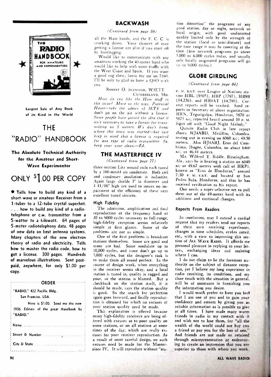
THE
RADIO HANDBOOK
FOR AMATEURS AND EXPERIMENTERS
Largest Sale of Any Book
of its Kind in the World
THE
"RADIO" HANDBOOK
The Absolute Technical Authority for the Amateur and Short -
Wave Experimenter
ONLY 9.00 PER COPY
Tells how to build any kind of a
short -wave or amateur Receiver from a
1 -tuber to a 12 -tube crystal superhet. ... how to build any kind of a radio- telephone or c.w. transmitter from a
5- watter to a kilowatt. 64 pages of 5 -meter radiotelephony data. 48 pages
of new data on best antenna systems. Many chapters of the new electron theory of radio and electricity. Tells how to master the radio code, how to get a license. 300 pages. Hundreds of marvelous illustrations. Sent post- paid, anywhere, for only $1.00 per copy.
ORDER
"RADIO," 422 Pacific Bldg.,
San Franciso, USA.
Here is $1.00. Send me the new
1936 Edition of the great Handbook by
"RADIO."
Name
Street & Number
City & State
96
BACKWASH (Continued from page 86)
all the Ham bands, and the F. C. C. is cracking down. Your chances of ever getting a license are slim if you start off by bootlegging.
Would like to communicate with any amateurs working the 40 -meter band who would like to help with some traffic with the West Coast and Spain. If you want a good rag chew, listen for me on 7160. I'll be only to glad to have a QSO with you.
RORERT O. SLEMMER, W3ETE CUMBERLAND, DID.
How do you like the Ham stuff in this issue? More on the way. Potential Hans -take the advice of 3ETE and don't go on the air without a license. Some people have gained the idea that it isn't necessary to have a license for trans- mitting on 5 meters. We don't know where this story was started -but just keep in mind that a license is required for any type of radio transmitter. So. keep your nose clean. -Ed.
THE MASTERPIECE IV (Continued from page 77)
three -section Litz wound coils each tuned by a 100 -mmfd air condenser. Both coil and condenser insulation is isolantite. Again large shields 3" in diameter and 4 11/16" high are used to insure no im- pairment of the efficiency of these very excellent tuned circuits.
High Fidelity 'I'he admission, amplification and final
reproduction of the frequency band of 30 to 9000 cycles necessary to full -range, high -fidelity reception seems relatively simple at first glance. Some of the problems are not as simple.
One of the first problems is broadcast stations themselves. Some are good and many are bad. Some modulate up to 10,000 cycles, and some don't go up to 5,000 cycles, but the designer's task is to make them all sound perfect. In the course of design work, when everything in the receiver seems okay, and a local station is tuned in, quality is ragged and poor, so the station is blamed. But a checkback on the station itself, if it should be made, says the station quality is good. So the search for perfection again goes forward, and finally reproduc- tion is obtained for which no excuses of poor station quality need be made.
This explanation is offered because many high -fidelity receivers are being of- fered with excuses as to poor quality on some stations, or on all stations at some times of the day, which are really ex- cuses for poor receiver reproduction. As a result of most careful design, no such excuses need be made for the Master- piece IV. It will reproduce without "sta-
tion distortion" the programs of any good station, day or night, network or local origin. with good undistorted quality limited only by the strength of the station (local or semi- distant) and the tone range it may be covering at the time (few network programs go above 5,000 to 6,000 cycles today, and usually only locally originated programs will go up to 9,000 cycles.)
GLOBE GIRDLING (Continued from page 64)
P. M. E.S.T. over League of Nations sta- tion HBL (9505), HBP (7797), HB9B (14,236), and HB9AT (14,290). Cor- rect reports will be verified. Send re- ports to Secretary of above organization. HRN, Tegucigalpa, Honduras, 5870 or 5875 KC, reported heard around 10 P. M. Signs off with "Good Night Melody."
Quixite Radio Club in late report shows H J4ABD, Medillin, Colombia. testing out in evening on 6060 Kc; 49.50 meters. Also HJ4ABJ, Ecos del Corn- brima, Ibagne, Colombia, on about 6460 KC, or 46.44 meters.
Mr. Wilfred T. Siddle, Birmingham, Ala., says he is hearing a station on 6040 KC or 49.67 meters with call of HRP1, known as "Ecos de Honduras," around 7:30 P. M. E.S.T. and located at San Pedro Sula, Honduras, and that he has received verification to his report.
One needs a super -selective set to pull them out of the 49 -meter band with its additions and continual changes.
Reports From Readers
In conclusion, may I extend a cordial request that my readers send me reports of their own receiving experiences, changes in time schedules, errors noted. etc., with a view to improving this sec- tion of ALL WAVE RADIO. It affords me personal pleasure in replying to your let- ters, exchanging ideas and assisting where I can.
I do not claim to be the foremost au- thority on the subject of distance recep- tion, yet I believe my long experience in radio receiving, its conditions, and my close touch with the situation in general,. will be of assistance in furnishing you the information you desire.
I would much prefer to have you feel that I am one of you and to gain your confidence and esteem by giving you as. reliable information as is possible to give at all times. I have made many warm .
friends in radio in my contact with it and wish not to lose them, for "all the wealth of the world could not buy you a friend or pay you for the loss of one. "' And friends are not made or retained' through misrepresentation or endeavor- ing to create an impression that you are superior to those with whom you work..
www.americanradiohistory.com

Weve made o
and
Wëi1adyou liked our first issue
You!11 want toreceive every issue early
1Z MONTIS Subsci4pboii
ALL -WAVE RADIO 200 FIFTH AVE. NEW YORK CITY
GENTLEMEN: Enclosed please find
for 12 Monlhs subscription }_s( 2.00 inCanada
I
I I I
I
M . O, SOCASH
CHECK
www.americanradiohistory.com

Don't Let a Poor Aerial Spoil Otherwise Excellent Reception The BEST Costs No More! Why Be Satisfied with Imitations?
As a result of LYNCH pioneering in the Aerial Field, many hundreds of thousands of antennas have been sold. But LYNCH HI -FI Antennas still maintain their superiority- technically, mechanically and electrically. There's a Reason! Competitors have copied the fundamentals of noise -free aerials, but they cannot duplicate LYNCH PERFORMANCE.
LYNCH HI -FI Antennas are Patented and Guaranteed.
NOISE- REDUCING TWINS LYNCH HI -FI ASSEMBLED ANTENNA
All ready to hang. Saves 90% of installation time. Any novice can install it- quickly, easily, correctly. Makes every set perform better on ALL waves. Results are 6.755 amazing.
The ONLY Two Companion Devices For Reducing Noise on ALL Waves!
LYNCH FILTERADIO Cuts out objectionable noise from the light line, consumes no current. Makes interference from circuit breakers, motor generators, etc., practically negligible. Easy to install; simple to adjust. One type 00 serves all purposes. List
A 40% discount is allowed to members of the I. S. W. C.TT if local jobber or dealer cannot supply you, order direct.
List
H. LYNCH, Inc., Dept A W., 227 Fulton St New York, N Y.
PIONEER OF NOISE- REDUCING AERIALS
Printed In the B. S. A.
www.americanradiohistory.com