); Use Cases for Operation in White Space Frequency … · Use Cases for Operation in White Space...
66
ETSI TR 102 907 V1.2.1 (2012-11) Reconfigurable Radio Systems (RRS); Use Cases for Operation in White Space Frequency Bands Technical Report
Transcript of ); Use Cases for Operation in White Space Frequency … · Use Cases for Operation in White Space...

ETSI TR 102 907 V1.2.1 (2012-11)
Reconfigurable Radio Systems (RRS); Use Cases for Operation in White Space Frequency Bands
Technical Report

ETSI
ETSI TR 102 907 V1.2.1 (2012-11) 2
Reference RTR/RRS-01015
Keywords M2M, radio, use case, white space
ETSI
650 Route des Lucioles F-06921 Sophia Antipolis Cedex - FRANCE
Tel.: +33 4 92 94 42 00 Fax: +33 4 93 65 47 16
Siret N° 348 623 562 00017 - NAF 742 C
Association à but non lucratif enregistrée à la Sous-Préfecture de Grasse (06) N° 7803/88
Important notice
Individual copies of the present document can be downloaded from: http://www.etsi.org
The present document may be made available in more than one electronic version or in print. In any case of existing or perceived difference in contents between such versions, the reference version is the Portable Document Format (PDF).
In case of dispute, the reference shall be the printing on ETSI printers of the PDF version kept on a specific network drive within ETSI Secretariat.
Users of the present document should be aware that the document may be subject to revision or change of status. Information on the current status of this and other ETSI documents is available at
http://portal.etsi.org/tb/status/status.asp
If you find errors in the present document, please send your comment to one of the following services: http://portal.etsi.org/chaircor/ETSI_support.asp
Copyright Notification
No part may be reproduced except as authorized by written permission. The copyright and the foregoing restriction extend to reproduction in all media.
© European Telecommunications Standards Institute 2012.
All rights reserved.
DECTTM, PLUGTESTSTM, UMTSTM and the ETSI logo are Trade Marks of ETSI registered for the benefit of its Members. 3GPPTM and LTE™ are Trade Marks of ETSI registered for the benefit of its Members and
of the 3GPP Organizational Partners. GSM® and the GSM logo are Trade Marks registered and owned by the GSM Association.
ETSI
ETSI TR 102 907 V1.2.1 (2012-11) 3
Contents
Intellectual Property Rights ................................................................................................................................ 5
Foreword ............................................................................................................................................................. 5
Introduction ........................................................................................................................................................ 5
1 Scope ........................................................................................................................................................ 6
2 References ................................................................................................................................................ 6
2.1 Normative references ......................................................................................................................................... 6
2.2 Informative references ........................................................................................................................................ 6
3 Definitions and abbreviations ................................................................................................................... 7
3.1 Definitions .......................................................................................................................................................... 7
3.2 Abbreviations ..................................................................................................................................................... 8
4 Motivation, goals ...................................................................................................................................... 9
5 Use Cases ................................................................................................................................................. 9
5.1 Overview ............................................................................................................................................................ 9
5.2 Mid-/long range wireless access over white space frequency bands ................................................................ 10
5.2.1 General Use Case Description .................................................................................................................... 10
5.2.2 Stakeholders ................................................................................................................................................ 12
5.2.3 Scenarios ..................................................................................................................................................... 13
5.2.3.1 Mid-/long range, no mobility ................................................................................................................ 13
5.2.3.2 Mid-/long range, low mobility .............................................................................................................. 13
5.2.3.3 Mid-/long range, high mobility ............................................................................................................. 14
5.2.4 Information Flow ........................................................................................................................................ 14
5.2.4.1 Spectrum allocation when base station powers on ................................................................................ 16
5.2.4.2 Incumbent protection (Switch from TVWS frequency band to licensed TD-LTE frequency band or candidate TVWS frequency band) .................................................................................................... 17
5.2.4.3 Radio Resource Optimization (Switch from licensed TD-LTE frequency band to TVWS frequency band) ..................................................................................................................................... 18
5.2.5 Derived potential System Requirements ..................................................................................................... 19
5.3 Short range wireless access over white space frequency bands ....................................................................... 20
5.3.1 General Use Case Description .................................................................................................................... 20
5.3.2 Stakeholders ................................................................................................................................................ 21
5.3.3 Scenarios ..................................................................................................................................................... 21
5.3.3.1 Networks without coexistence management ......................................................................................... 21
5.3.3.2 Networks with distributed coexistence management ............................................................................ 21
5.3.3.3 Networks with centralized coexistence management ............................................................................ 22
5.3.3.4 Hybrid of networks with distributed and centralized coexistence management ................................... 23
5.3.4 Information Flow ........................................................................................................................................ 24
5.3.5 Derived potential System Requirements ..................................................................................................... 28
5.4 Ad-hoc networking over white space frequency bands .................................................................................... 29
5.4.1 General Use Case Description .................................................................................................................... 29
5.4.2 Stakeholders ................................................................................................................................................ 29
5.4.3 Scenarios ..................................................................................................................................................... 30
5.4.3.1 Device-to-device connectivity............................................................................................................... 30
5.4.3.2 Ad-hoc networking................................................................................................................................ 30
5.4.3.3 Infrastructure supported ad-hoc networking ......................................................................................... 31
5.4.4 Information Flow ........................................................................................................................................ 31
5.4.5 Derived potential System Requirements ..................................................................................................... 32
5.5 Combined Ad-hoc networking and wireless access over white space frequency bands ................................... 32
5.5.1 General Use Case Description .................................................................................................................... 32
5.5.2 Stakeholders ................................................................................................................................................ 33
5.5.3 Scenarios ..................................................................................................................................................... 33
5.5.3.1 Expanding the coverage of the infrastructure ........................................................................................ 34
5.5.3.2 Resolving cases of congested access to the infrastructure .................................................................... 34
5.5.3.3 Direct device-to-device links in TVWS managed by access points or femto cells ............................... 34

ETSI
ETSI TR 102 907 V1.2.1 (2012-11) 4
5.5.4 Information Flow ........................................................................................................................................ 35
5.5.5 Derived potential System Requirements ..................................................................................................... 36
5.6 Sporadic use of TV white space frequency bands ............................................................................................ 37
5.6.1 General Use Case Description .................................................................................................................... 37
5.6.2 Stakeholders ................................................................................................................................................ 37
5.6.3 Scenario Case Description .......................................................................................................................... 38
5.6.3.1 Lighter infrastructure deployment through larger cell sizes .................................................................. 38
5.6.3.2 Increased spectral efficiency through reduced propagation loss ........................................................... 38
5.6.3.3 Increased spectral efficiency through extended macro diversity ........................................................... 39
5.6.3.4 TVWS Band-Switch in case that incumbent user re-enters .................................................................. 40
5.6.3.5 Carrier Aggregation between IMT bands and TV WS band ................................................................. 40
5.6.4 Information Flow ........................................................................................................................................ 43
5.6.4.1 Adding a New RAT Component Carrier into UHF TVWS Band ......................................................... 43
5.6.4.2 UHF TVWS Band Component Carrier Reconfiguration ...................................................................... 44
5.6.4.3 Incumbent protection ............................................................................................................................ 45
5.6.5 Derived potential system requirements ....................................................................................................... 46
5.7 Backhaul link using TV white space frequency bands ..................................................................................... 46
5.7.1 General Use Case Description .................................................................................................................... 46
5.7.2 Stakeholders ................................................................................................................................................ 47
5.7.3 Scenarios ..................................................................................................................................................... 47
5.7.3.1 Relay node backhaul link ...................................................................................................................... 47
5.7.4 Information Flow ........................................................................................................................................ 48
5.7.4.1 Information Flow for Backhaul Link Initial Work Procedure ............................................................... 48
5.7.4.2 Information Flow for Incumbent Protection on Backhaul Link ............................................................ 49
5.7.5 Derived potential System Requirements ..................................................................................................... 50
5.8 MBMS operating in TV white space frequency bands ..................................................................................... 50
5.8.1 General Use Case Description .................................................................................................................... 50
5.8.2 Stakeholders ................................................................................................................................................ 50
5.8.3 Scenarios ..................................................................................................................................................... 51
5.8.3.1 LTE MBMS in TV white space frequency bands ................................................................................. 51
5.8.4 Information Flow ........................................................................................................................................ 52
5.9 Machine communications (M2M) systems operating in white space TV bands .............................................. 53
5.9.1 General use case description ....................................................................................................................... 53
5.9.2 Stakeholders ................................................................................................................................................ 53
5.9.3 Scenarios ..................................................................................................................................................... 53
5.9.4 Information flow ......................................................................................................................................... 54
5.9.5 Derived potential System Requirements ..................................................................................................... 55
6 Potential System Requirements .............................................................................................................. 55
7 Technical challenges .............................................................................................................................. 57
7.1 Coexistence ...................................................................................................................................................... 58
7.2 The role of sensing ........................................................................................................................................... 59
7.3 Challenges derived from TVWS propagation characteristics ........................................................................... 59
7.4 Challenges in regard to co-existence with RF Cable Systems .......................................................................... 59
Annex A: Summary of current regulatory status................................................................................ 61
A.1 FCC regulation on White Space in the UHF TV bands ......................................................................... 61
A.2 Current activities in CEPT on White Space Usage in the UHF TV bands ............................................. 61
Annex B: Using white space frequency bands through temporary exclusive access rights ............ 63
B.1 Concept of temporary exclusive access rights ........................................................................................ 63
B.2 Information Flow .................................................................................................................................... 64
History .............................................................................................................................................................. 66

ETSI
ETSI TR 102 907 V1.2.1 (2012-11) 5
Intellectual Property Rights IPRs essential or potentially essential to the present document may have been declared to ETSI. The information pertaining to these essential IPRs, if any, is publicly available for ETSI members and non-members, and can be found in ETSI SR 000 314: "Intellectual Property Rights (IPRs); Essential, or potentially Essential, IPRs notified to ETSI in respect of ETSI standards", which is available from the ETSI Secretariat. Latest updates are available on the ETSI Web server (http://ipr.etsi.org).
Pursuant to the ETSI IPR Policy, no investigation, including IPR searches, has been carried out by ETSI. No guarantee can be given as to the existence of other IPRs not referenced in ETSI SR 000 314 (or the updates on the ETSI Web server) which are, or may be, or may become, essential to the present document.
Foreword This Technical Report (TR) has been produced by ETSI Technical Committee Reconfigurable Radio Systems (RRS).
Introduction The present document describes how radio networks can operate, on a secondary basis, in frequency bands assigned/licensed to one (or several) incumbent user(s).

ETSI
ETSI TR 102 907 V1.2.1 (2012-11) 6
1 Scope The present document describes Use Cases for the Operation of Reconfigurable Radio Systems within White Spaces in the UHF 470 MHz to 790 MHz frequency band and gives an overview on methods for protecting the primary/incumbent users like TV broadcasts and wireless microphones.
2 References References are either specific (identified by date of publication and/or edition number or version number) or non-specific. For specific references, only the cited version applies. For non-specific references, the latest version of the reference document (including any amendments) applies.
Referenced documents which are not found to be publicly available in the expected location might be found at http://docbox.etsi.org/Reference.
NOTE: While any hyperlinks included in this clause were valid at the time of publication, ETSI cannot guarantee their long term validity.
2.1 Normative references The following referenced documents are necessary for the application of the present document.
Not applicable.
2.2 Informative references The following referenced documents are not necessary for the application of the present document but they assist the user with regard to a particular subject area.
[i.1] CEPT Report 24: "A preliminary assessment of the feasibility of fitting new/future applications/services into non-harmonised spectrum of the digital dividend (namely the so-called 'white spaces' between allotments)", July 2008.
[i.2] CEPT ECC Report 159: "Technical and operational requirements for the possible operation of cognitive radio systems in the 'White spaces' of the frequency band 470-790 MHz", January 2011.
[i.3] FCC Report 10-174: "Second memorandum opinion and order - in the matter of unlicensed operation in the TV Broadcast bands - additional spectrum for unlicensed devices below 900 MHz and in the 3 GHz band", 23. Sept. 2010.
[i.4] FCC Erratum: "Corrections to FCC Report 10-174", DOC-302279A1, 19. Oct. 2010.
NOTE: See http://hraunfoss.fcc.gov/edocs_public/attachmatch/DOC-302279A1.pdf.
[i.5] "Implementing Geolocation", Ofcom UK, 9. Nov. 2010.
NOTE: See http://stakeholders.ofcom.org.uk/consultations/geolocation/.
[i.6] "Combination of Centralized & Decentralized Database and Terminal-based Spectrum Sensing for Secondary Spectrum Access, Markus Mueck, Marco Di Renzo, Mérouane Debbah and Tobias Renk", IEEE International Conference on Wireless Information Technology and Systems (ICWITS), Hawaii, USA, 2010.
[i.7] "Opportunistic relaying for Cognitive Radio enhanced cellular networks: Infrastructure and initial results", Mueck, Markus Dominik; Di Renzo, Marco; Debbah, Merouane; Wireless Pervasive Computing (ISWPC), 2010 5th IEEE International Symposium on, 2010, Page(s): 556 - 561.
[i.8] IEEE 802: "Standard for Local and Metropolitan Area Networks: overview and architecture".

ETSI
ETSI TR 102 907 V1.2.1 (2012-11) 7
3 Definitions and abbreviations
3.1 Definitions For the purposes of the present document, the following terms and definitions apply:
cognitive radio: radio, which has the following capabilities:
• to obtain the knowledge of radio operational environment and established policies and to monitor usage patterns and users' needs;
• to dynamically and autonomously adjust its operational parameters and protocols according to this knowledge in order to achieve predefined objectives, e.g. more efficient utilization of spectrum; and
• to learn from the results of its actions in order to further improve its performance.
incumbent radio service: radio service authorized for operation on a given frequency band with a regulatory priority
NOTE: In the frequency band 470 MHz to 790 MHz, the following radio services are considered as incumbent radio services:
� Terrestrial Broadcasting Service (BS) including DVB-T in particular.
� Program Making and Special Event (PMSE) services including radio microphones in particular.
� Radio Astronomy Service (RAS) in the 608 MHz to 614 MHz band.
� Aeronautical Radio Navigation Service (ARNS) in the 645 MHz to 790 MHz band.
Program Making and Special Events: general term to describe equipment used in program making
NOTE: Within the 470 MHz to 790 MHz band the use is mainly Radio microphones, In Ear Monitors (IEM) and Audio links. Radio microphones may be single channel or in excess of 100 channels, IEM are fixed transmitters (at the audio desk) and a receiver carried by the artist or presenter and will move around the site, they are stereo transmissions, there can be up to 30 IEM in some productions ranging up to many hundreds for events such as the Olympics. Audio links can be considered higher power radio microphones but often using a stereo mode.
radio system: system capable to communicate some user information by using electromagnetic waves
NOTE: Radio system is typically designed to use certain radio frequency band(s) and it includes agreed schemes for multiple access, modulation, channel and data coding as well as control protocols for all radio layers needed to maintain user data links between adjacent radio devices.
reconfigurable radio systems: generic term for radio systems encompassing Software Defined and/or Cognitive Radio Systems
use case: description of a system's behaviour as it responds to a request that originates from outside of that system
NOTE: In other words, a use case describes "who" can do "what" with the system in question. The use case technique is used to capture a system's behavioural requirements by detailing scenario-driven threads through the functional requirements.
White Space (WS): part of the spectrum, which is available for a radiocommunication application (service, system) at a given time in a given geographical area on a non-interfering/nonprotected basis with regard to primary services and other services with a higher priority on a national basis

ETSI
ETSI TR 102 907 V1.2.1 (2012-11) 8
3.2 Abbreviations For the purposes of the present document, the following abbreviations apply:
3GPP 3rd Generation Partnership Project AP Access Point ARNS Aeronautical Radio Navigation Service BCCH Broadcast Control Channel BS Base Station BS Broadcasting Service CA Carrier Aggregation CAPEX Capital expenditures CC Component Carrier CCC Cognitive Control Channel CCP Central Control Point CCR Cognitive Control Radio CEPT Conférence Européenne des Administrations des Postes et des Télécommunications CPC Cognitive Pilot Channel CR Cognitive Radio CSMA Carrier Sense Multiple Access DL Downlink DTV Digital TeleVision DVB-T Digital Video Broadcasting - Terrestrial EIRP Equivalent Isotropically Radiated Power eNB evolved Node B FCC Federal Communications Commission FDD Frequency Division Duplex GNSS Global Navigation Satellite System GPS Global Positioning System GSM Global System for Mobile Communication HO Handover HSPA High Speed Packet Access IEM In Ear Monitor IMT International Mobile Telecommunications ISM Industrial, Scientific and Medical LTE Long Term Evolution MBMS Multimedia Broadcast Multicast Service MBR Maximum Bit Rate MBSFN Multimedia Broadcast multicast service Single Frequency Network MCCH MBMS point-to-multipoint Control Channel MCE Multi-cell/multicast Coordination Entity MME Mobility Management Entitiy MNO Mobile Network Operator MTCH MBMS point-to-multipoint Traffic Channel NW Network OAM Operations, Administration and Maintenance OPEX Operational expenditure PMSE Program Making and Special Events QoS Quality of Service RAS Radio Astronomy Service RAT Radio Access Technology REQ Requirement RF Radio Frequency RRM Radio Resource Management RRS Reconfigurable Radio System SDR Software Defined Radio TDD Time Division Duplex TD-LTE Time Division Duplex - Long Term Evolution TR Technical Report TV Television TVBD Television Band Device

ETSI
ETSI TR 102 907 V1.2.1 (2012-11) 9
TVWS TV White Space UE User Equipment UHF Ultra High Frequency
NOTE: Within the context of the present document: 470 MHz to 862 MHz.
UL Uplink UMTS Universal Mobile Telecommunication System WLAN Wireless Local Area Network WRC World Radio Conference WS White Space
4 Motivation, goals As a result of the transition from analogue to digital TV transmission in the 470 MHz to 862 MHz UHF frequency band, certain parts of the spectrum are no longer used for TV transmission in some regions. Moreover, bands used for TV transmissions are geographically interleaved to avoid causing interference to co-channel or adjacent channel DTV transmitters - forming the so called TV white spaces. These characteristics of spectrum usage in the UHF band provide an opportunity for deploying new wireless services.
These opportunities comprise:
• Reallocated bands which are made available for other services. In Europe for example, the 800 MHz band, i.e. the 790 MHz to 862 MHz sub-band, has been reserved for mobile services to be allocated for IMT services from the year 2015.
• Geographically interleaved bands (TV White Spaces - TVWS) available in the 470 MHz to 790 MHz sub-band. Based on CEPT definition: these are frequencies available for a radiocommunication application (service, system) at a given time in a given geographical area on a non-interfering/nonprotected basis with regard to incumbent services and other services with a higher priority on a national basis.
The present document focuses on the second case, namely on use cases for operation in white space frequency bands. The use cases assume a regulatory environment where the TV White Spaces can be used for free (spectrum commons). A different potential future regulatory environment allowing e.g. secondary spectrum trading (paid with some sort of exclusivity) is described in annex B.
5 Use Cases
5.1 Overview Use Cases according to definition in clause 3.1 will describe a system from the user point of view, describing what the actor achieves interacting with the system. Use Cases are used for deriving requirements on the system. For this purpose each Use Case described in the following clause is documented in the same way by using the same structure:
1) General Use Case Description
2) Stakeholders
3) Scenario
4) Information Flow
5) Derived potential System Requirements
Below is the list of use cases, which are described in detail in the next clauses:
• Mid-/long range wireless access over white space frequency bands:
- Mid-/long range, no mobility

ETSI
ETSI TR 102 907 V1.2.1 (2012-11) 10
- Mid-/long range, low mobility
- Mid-/long range, high mobility
• Short range wireless access over white space frequency bands:
- Networks without coexistence management
- Networks with distributed coexistence management
- Networks with centralized coexistence management
- Hybrid of networks with distributed and centralized coexistence management
• Ad-hoc networking over white space frequency bands:
- Device-to-device connectivity
- Ad-hoc networking
- Infrastructure supported ad-hoc networking
• Combined Ad-hoc networking and wireless access over white space frequency bands:
- Expanding the coverage of the infrastructure
- Resolving cases of congested access to the infrastructure
- Direct device-to-device links in TVWS managed by access points or femto cells
• Sporadic use of TV white space frequency bands:
- Lighter infrastructure deployment through larger cell sizes
- Increased spectral efficiency through reduced propagation loss
- Increased spectral efficiency extended macro diversity
- TVWS Band-Switch in case that incumbent user re-enters
- Carrier Aggregation between IMT and TVWS bands
• Backhaul link using TV white space frequency bands:
- Relay node backhaul link
• Multimedia Broadcast Multicast Service (MBMS) operating in TV white space frequency bands:
- LTE MBMS in TV white space frequency bands
• Machine communications systems operating in white space TV bands
5.2 Mid-/long range wireless access over white space frequency bands
5.2.1 General Use Case Description
Internet access is provided from a base station to the end users by utilizing white space frequency bands over ranges similar to today's cellular systems, e.g. in the range of 0 km to 10 km.
This use case can be divided into three scenarios dependent on the mobility of the end-user devices:
• no mobility, e.g. the end-user device is fixed mounted at a wall;
• low mobility, e.g. the end-user can walk around with his device;

ETSI
ETSI TR 102 907 V1.2.1 (2012-11) 11
• high mobility, e.g. the end-user is travelling by car or a train.
This differentiation is made because the constraints for detecting incumbent users or other secondary users as well as on retrieving the geographical position may differ dependent on the mobility of the users.
Communication in White Space Frequency Bands
Communication in White Space Frequency Bands
Figure 1: Mid-/long range wireless access over white space frequency bands
In this use case, multimode user terminals (i.e. terminals that support multi-RAT in licensed spectrums for instance HSPA and LTE) are also provided with the capability of accessing TV White Space spectrum bands in order to provide wireless broadband access (e.g. TD-LTE) for instance in rural areas where high data rate connections are commonly not available. This use case takes the benefit of the excellent propagation performance of a radio network operating in TV White Space frequency bands i.e. 470 MHz to 790 MHz in Europe/Region 1.
TDD can be considered more suitable for a secondary/overlay spectrum access compared with FDD for the following reasons:
1) TDD only needs one frequency band, so it is simpler to find one single suitable white space frequency band. For FDD a pair of separated frequency bands (UL/DL) is required with strict separation bandwidth requirements that makes candidates frequency bands more difficult to find.
2) With two frequency bands used by FDD, there are more chances to interfere with incumbent users on any of the 2 bands than TDD in its single band - furthermore interference on any of the 2 frequency bands will result in a handover or a break of the link both DL and UL.
3) It appears to be simpler to detect incumbent users on one single frequency band (TDD) than on a pair of frequency bands (FDD).
4) TDD - allowing asymmetric DL/UL data connection on a single frequency band may fit well a dynamic spectrum assignment with optimized/dynamic channel bandwidth.

ETSI
ETSI TR 102 907 V1.2.1 (2012-11) 12
On f1
On f2
DL:
UL:
On f1UL
FDD
TDDDL
RF BB
RF
IMT Tx/Rx:
Sensing Rx:Data
Sensing Results
The detector needs to detect two frequency bands.
The detector needs to detect only one frequency band.
Detector
Quiet Period
Quiet Period
On f1
On f2
DL:
UL:
On f1UL
FDD
TDDDL
RF BB
RF
IMT Tx/Rx:
Sensing Rx:Data
Sensing Results
The detector needs to detect two frequency bands.
The detector needs to detect only one frequency band.
Detector
Quiet Period
Quiet Period
Figure 2: Architecture Illustration of the Incumbent Signal Detector
NOTE 1: The traditional drawback for a TDD system, i.e. network synchronization, is now shared with the FDD system which also needs to be network synchronized because of the need to schedule quiet periods for incumbent signal sensing e.g. synchronized with all neighbour cells.
NOTE 2: The increased interference level at the DL/UL switchover, especially in over-reach conditions may be another concern of the TDD system. In order to solve this issue, the frequency band of the impacted neighbour cells can be pre-configured in such a manner that it is different from the cell which may lead to over-reach problem - this behaviour is inherent to TDD system and solutions used in current TDD wide area such as TD-SCDMA and WIMAX deployment can be re-used.
NOTE 3: The present use case i.e. TD-LTE operating in TV White Space focuses primarily on low/no mobility scenarios with larger cells (radius up to tens of kilometres) but high mobility scenarios are not excluded and remain for further study.
5.2.2 Stakeholders
• End users: the users of the devices accessing internet and other similar mobile data services.
• (White Space) Operator: operates and maintains the required infrastructure; may operate other networks in other frequency bands.
• White Space database service provider: in case frequency utilization of frequency bands is available in geo-location databases as e.g. described in [i.5], this entity provides up-to-date information on incumbent frequency usage.
• External entities: e.g. Internet service provider, in case (White Space) Operator only provides the radio access on white space.

ETSI
ETSI TR 102 907 V1.2.1 (2012-11) 13
5.2.3 Scenarios
5.2.3.1 Mid-/long range, no mobility
In this scenario, wireless access is provided from a base station towards fixed devices, e.g. a fixed mounted home base station/access point. The geo-location from both the base station as well as from the fixed device are well-known.
Range (order of magnitude): 0 km to 10 km
Mobility: None (0 km/h)
Geo-Location methods: e.g. GNSS (GPS) or professional installation
e.g. WifiCommunication in WhiteSpace Frequency Bands
e.g. WifiCommunication in WhiteSpace Frequency Bands
Figure 3: Mid-/long range wireless access, no mobility
5.2.3.2 Mid-/long range, low mobility
In this scenario, wireless access is provided from a base station towards mobile devices where the users have low mobility, e.g. they are staying at their location or walking. In that respect, sensing results for incumbent users retrieved for the current location are not getting invalid due to the mobility of the user.
The geo-location from the base station is well-known. The geo-location from the mobile device has to be determined during operation, e.g. via GPS or cellular positioning systems.
Range (order of magnitude): 0 km to 10 km
Mobility: 0 km/h to 20 km/h
Geo-Location methods: e.g. GPS or cellular positioning systems
Communication in WhiteSpace Frequency BandsCommunication in WhiteSpace Frequency Bands
Figure 4: Mid-/long range wireless access, low mobility

ETSI
ETSI TR 102 907 V1.2.1 (2012-11) 14
5.2.3.3 Mid-/long range, high mobility
In this scenario, wireless access is provided from a base station towards mobile devices and the mobile devices may move fast, e.g. because a user is in a car or a train. In that respect, sensing results for incumbent users retrieved for the current location may get invalid quickly due to the mobility of the user. Thus, this use case sets high constraints for the detection of incumbent users.
The geo-location from the base station is well-known. The geo-location from the mobile device has to be determined during operation, e.g. via GPS or cellular positioning systems.
Range (order of magnitude): 0 km to 10 km
Mobility: 0 km/h to 250 km/h
Geo-Location methods: e.g. GPS
Communication in WhiteSpace Frequency Bands
Communication in WhiteSpace Frequency Bands
Figure 5: Mid-/long range wireless access, high mobility
5.2.4 Information Flow
The available TVWS frequency band is considered based on location rather than in time, it is assumed that TVWS would be largely available in rural area and in time. However dynamic change in the availability of the bands can not be excluded and thus has to be taken into account by the system.
In the case of a Network Centric solution, the terminal can get the required information from its current connectivity and its current RAT i.e. TD-LTE operating in TVWS, or from another RAT e.g. HSPA in 3G bands.
Once the terminal accesses the network it can be left under the control of the network, higher layer signalling can be used for this purpose e.g. handover command to hand-off to a new frequency or system broadcast messages can be used to notify terminals about change of the frequency.
A terminal centric solution i.e. where the terminal is able of detecting then accessing suitable TVWS frequencies with or without the help of the network or a third party e.g. CPC and/or geolocation Database, is possible but not elaborated in this scenario.
The dynamic spectrum access to the TVWS spectrum frequency band could be achieved by a centralized mode.

ETSI
ETSI TR 102 907 V1.2.1 (2012-11) 15
Figure 6: Access to TVWS, centralized mode
As shown in Figure 6, a central control point is deployed to manage the access of the TD-LTE system to the TV White Space. It can be either an enhanced base station or a standalone node. The central control point may connect to a geo-location database to get the information of TVWS spectrum usage status. The geo-location database contains the information on the secondary user as well as the incumbent user. Alternatively, it may be able to collect the sensing results from base stations and then produce a radio environment map. It manages the spectrum allocation of the TVWS resource to the base stations. No negotiation is needed between the base stations in this case. When the base station switches on, it inquires from the central control point whether there are available TVWS frequencies. If allocated, the base station can reconfigure itself with the new allocated frequency bands, otherwise, the base station should operate in the TD-LTE frequency band instead. The base station may be enhanced with the capability of sensing TVWS spectrums and reports the sensing result to the central control point.
ETSI
ETSI TR 102 907 V1.2.1 (2012-11) 16
5.2.4.1 Spectrum allocation when base station powers on
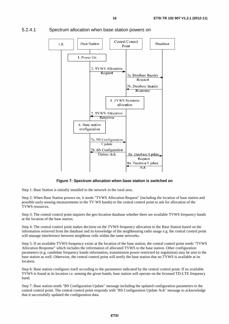
Figure 7: Spectrum allocation when base station is switched on
Step 1: Base Station is initially installed to the network in the rural area.
Step 2: When Base Station powers on, it sends "TVWS Allocation Request" (including the location of base station and possible early sensing measurements in the TV WS bands) to the central control point to ask for allocation of the TVWS resources.
Step 3: The central control point inquires the geo-location database whether there are available TVWS frequency bands at the location of the base station.
Step 4: The central control point makes decision on the TVWS frequency allocation to the Base Station based on the information retrieved from the database and its knowledge of the neighbouring radio usage e.g. the central control point will manage interference between neighbour cells within the same networks.
Step 5: If an available TVWS frequency exists at the location of the base station, the central control point sends "TVWS Allocation Response" which includes the information of allocated TVWS to the base station. Other configuration parameters (e.g. candidate frequency bands information, transmission power restricted by regulation) may be sent to the base station as well. Otherwise, the central control point will notify the base station that no TVWS is available at its location.
Step 6: Base station configures itself according to the parameters indicated by the central control point. If no available TVWS is found at its location i.e. sensing the given bands, base station will operate on the licensed TD-LTE frequency band.
Step 7: Base station sends "BS Configuration Update" message including the updated configuration parameters to the central control point. The central control point responds with "BS Configuration Update Ack" message to acknowledge that it successfully updated the configuration data.
ETSI
ETSI TR 102 907 V1.2.1 (2012-11) 17
Step 8: The central control point sends "Database Update Request" message including the updated configuration parameters to the geo-location database. The database responds with "Database Update Ack" message to acknowledge that it successfully updated the configuration data.
NOTE: The network may have some mechanisms to notify the UE about the current operating frequency of the base station. For example, in-band CPC on another RAT can be utilized. In this case, the UE under the coverage of the base station connects to the other RAT to obtain the operating TVWS frequency information and accesses to the TVWS frequency band.
5.2.4.2 Incumbent protection (Switch from TVWS frequency band to licensed TD-LTE frequency band or candidate TVWS frequency band)
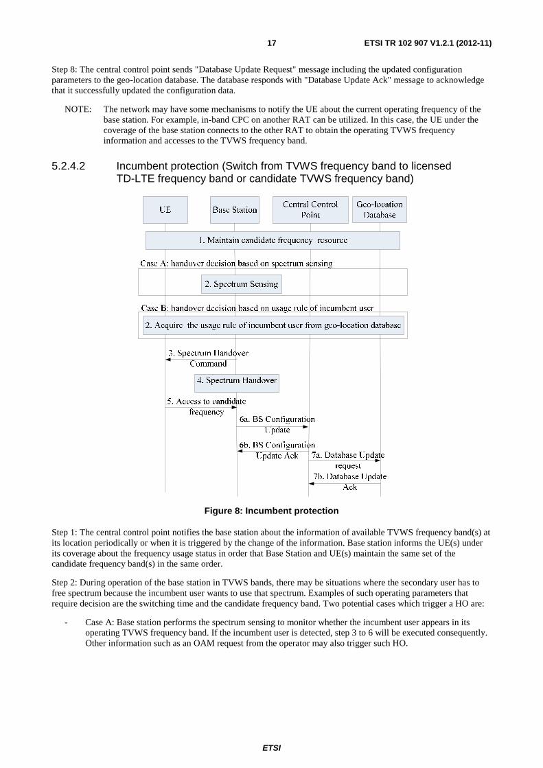
Figure 8: Incumbent protection
Step 1: The central control point notifies the base station about the information of available TVWS frequency band(s) at its location periodically or when it is triggered by the change of the information. Base station informs the UE(s) under its coverage about the frequency usage status in order that Base Station and UE(s) maintain the same set of the candidate frequency band(s) in the same order.
Step 2: During operation of the base station in TVWS bands, there may be situations where the secondary user has to free spectrum because the incumbent user wants to use that spectrum. Examples of such operating parameters that require decision are the switching time and the candidate frequency band. Two potential cases which trigger a HO are:
- Case A: Base station performs the spectrum sensing to monitor whether the incumbent user appears in its operating TVWS frequency band. If the incumbent user is detected, step 3 to 6 will be executed consequently. Other information such as an OAM request from the operator may also trigger such HO.

ETSI
ETSI TR 102 907 V1.2.1 (2012-11) 18
- Case B: The base station performs handover process based on the usage rule of incumbent user and frees the spectrum before the incumbent user appears. The base station acquires the usage rule of incumbent user from the geo-location database, i.e. information of available TVWS frequency band(s) with appearance time, duration time at its location periodically or when it is triggered by the change of the information. For this case, the usage rule is utilized to determine the switching time and candidate frequency band by the base station in step 3.
Step 3: Base station decides to switch the operating frequency to candidate frequency band in second highest priority and the switching time, and then notify UE(s) about the change of the frequency. For case B, the handover command is transmitted without the interference of incumbent user.
Step 4: Base station buffers the downlink transmitting packets of the connected mode UE(s) and then switches to the candidate frequency at the switching time.
Step 5: The related UE(s) will switch to the frequency accordingly at the occasion indicated by the base station at the switching time. The buffered downlink packets in base station are sent to UE(s) in order to ensure the service continuity.
Step 6: Base station sends "BS Configuration Update" message including the updated configuration parameters to the central control point. The central control point responds with "BS Configuration Update Ack" message to acknowledge that it successfully updated the configuration data.
NOTE: Step 6a can be performed before Step 5.
Step 7: The central control point sends Database Update Request message including the updated configuration parameters to the geo-location database. The database responds with Database Update Ack message to acknowledge that it successfully updated the configuration data.
5.2.4.3 Radio Resource Optimization (Switch from licensed TD-LTE frequency band to TVWS frequency band)
Figure 9: Radio Resource Optimization
Step 1: Base station operating on the licensed TD-LTE frequency sends "TVWS Allocation Request" to the central control point periodically.

ETSI
ETSI TR 102 907 V1.2.1 (2012-11) 19
Step 2: The central control point inquires the geo-location database if there are any available TVWS frequency bands at the location of the base station.
Step 3: If available TVWS frequency existing at the location of base station, the central control point sends "TVWS Allocation Response" which includes the information of allocated TVWS to the base station. Other configuration parameters (e.g. candidate frequency bands information, transmission power restricted by regulation) may be sent to base station as well. Otherwise, the central control point will notify base station that no TVWS is available at its location.
Step 4: Base station decides to switch the operating frequency to allocated TVWS frequency band and notify UE(s) about the change of the frequency.
Step 5: Base station buffers the downlink transmitting packets of the connected mode UE(s) and then switches to the allocated TVWS frequency after all the UE(s) have been informed.
Step 6: The related UE(s) will switch to the frequency accordingly at the occasion indicated by the base station. The buffered downlink packets in base station are sent to UE(s) in order to ensure the service continuity.
Step 7: Base station sends "BS Configuration Update" message including the updated configuration parameters to the central control point. The central control point responds with "BS Configuration Update Ack" message to acknowledge that it successfully updated the configuration data.
NOTE: Step 7a can be performed before Step 6.
Step 8: The central control point sends "Database Update Request" message including the updated configuration parameters to the database. The geo-location database responds with "Database Update Ack" message to acknowledge that it successfully updated the configuration data.
5.2.5 Derived potential System Requirements
In order to achieve the aim of the scenarios describe above, several system functionalities can be considered further for standardization:
REQ_01: Incumbent user protection
The impacts on TV receiving signal should be managed below an acceptable level. How well the incumbent user is protected determines the possibility whether the spectrum owners are willing to share their white space or not.
There are two phases for incumbent user protection:
1) secondary user has the capability to discover TVWS which is not occupied by incumbent user;
2) secondary user has to free the spectrum to incumbent user in a reasonable time after it appears.
REQ_02: Geo-location Database management
It should be possible to get information on incumbent user(s) and optionally also on secondary user(s) of the TVWS frequency bands from a reliable and secure geo-location database. The usage of TVWS frequency bands may need to be registered with the geo-location database. The operation of the geo-location database can be done by a third party service provider as e.g. described in [i.5].
REQ_03: Base Station based sensing
The market may be sensitive to the terminal price, so it would be beneficial that using white space would not add too much complexity on terminals. Terminals may not even support cognitive capability but while being SDR capable e.g. terminals can adapt and operate on new frequency bands and thus operate in TVWS. Cognitive capabilities may not be required for terminals; in this case the base stations are able to detect the incumbent signal (geo-location database plus sensing) without assistance from mobiles.
ETSI
ETSI TR 102 907 V1.2.1 (2012-11) 20
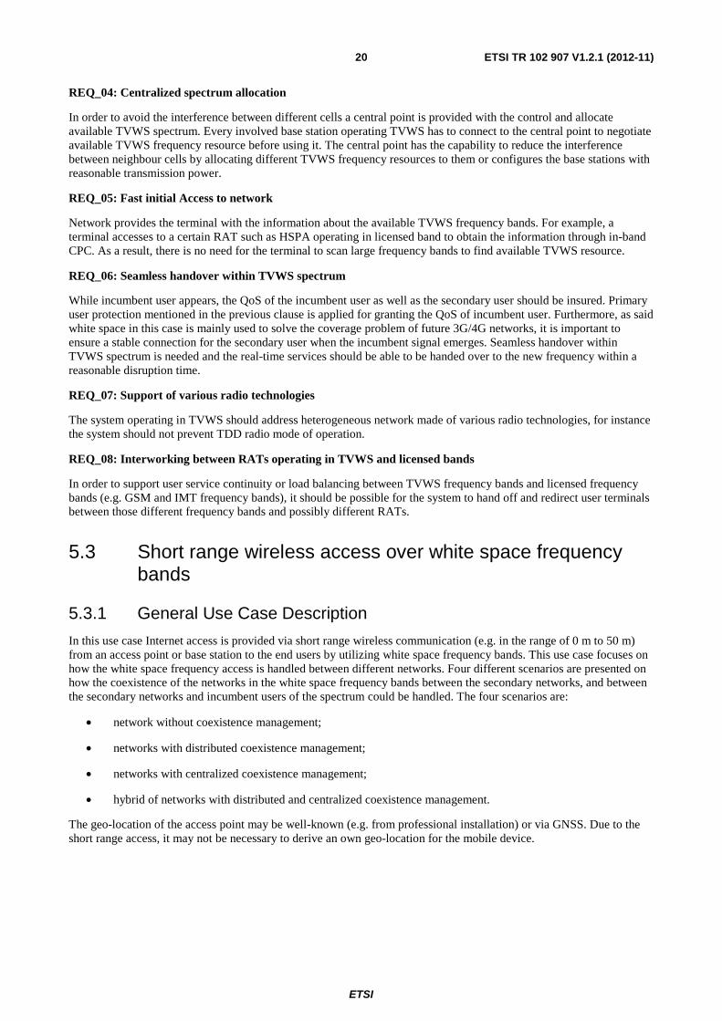
REQ_04: Centralized spectrum allocation
In order to avoid the interference between different cells a central point is provided with the control and allocate available TVWS spectrum. Every involved base station operating TVWS has to connect to the central point to negotiate available TVWS frequency resource before using it. The central point has the capability to reduce the interference between neighbour cells by allocating different TVWS frequency resources to them or configures the base stations with reasonable transmission power.
REQ_05: Fast initial Access to network
Network provides the terminal with the information about the available TVWS frequency bands. For example, a terminal accesses to a certain RAT such as HSPA operating in licensed band to obtain the information through in-band CPC. As a result, there is no need for the terminal to scan large frequency bands to find available TVWS resource.
REQ_06: Seamless handover within TVWS spectrum
While incumbent user appears, the QoS of the incumbent user as well as the secondary user should be insured. Primary user protection mentioned in the previous clause is applied for granting the QoS of incumbent user. Furthermore, as said white space in this case is mainly used to solve the coverage problem of future 3G/4G networks, it is important to ensure a stable connection for the secondary user when the incumbent signal emerges. Seamless handover within TVWS spectrum is needed and the real-time services should be able to be handed over to the new frequency within a reasonable disruption time.
REQ_07: Support of various radio technologies
The system operating in TVWS should address heterogeneous network made of various radio technologies, for instance the system should not prevent TDD radio mode of operation.
REQ_08: Interworking between RATs operating in TVWS and licensed bands
In order to support user service continuity or load balancing between TVWS frequency bands and licensed frequency bands (e.g. GSM and IMT frequency bands), it should be possible for the system to hand off and redirect user terminals between those different frequency bands and possibly different RATs.
5.3 Short range wireless access over white space frequency bands
5.3.1 General Use Case Description
In this use case Internet access is provided via short range wireless communication (e.g. in the range of 0 m to 50 m) from an access point or base station to the end users by utilizing white space frequency bands. This use case focuses on how the white space frequency access is handled between different networks. Four different scenarios are presented on how the coexistence of the networks in the white space frequency bands between the secondary networks, and between the secondary networks and incumbent users of the spectrum could be handled. The four scenarios are:
• network without coexistence management;
• networks with distributed coexistence management;
• networks with centralized coexistence management;
• hybrid of networks with distributed and centralized coexistence management.
The geo-location of the access point may be well-known (e.g. from professional installation) or via GNSS. Due to the short range access, it may not be necessary to derive an own geo-location for the mobile device.

ETSI
ETSI TR 102 907 V1.2.1 (2012-11) 21
Communication in WhiteSpace Frequency Bands
e.g. Fixed Access …
Communication in WhiteSpace Frequency Bands
e.g. Fixed Access …
Figure 10: Short range wireless access over white space frequency bands
5.3.2 Stakeholders
• End users: the users of the devices accessing internet and other similar mobile data services.
• (White Space) Operator: operates and maintains the required infrastructure; may operate other networks in other frequency bands.
• White Space geo-location database service provider: in case frequency utilization of frequency bands is available in databases, this entity provides up-to-date information on incumbent frequency usage.
• External entities: e.g. Internet service provider, in case (White Space) Operator only provides the radio access on white space.
5.3.3 Scenarios
5.3.3.1 Networks without coexistence management
In this scenario one or more independent networks access white space frequency bands. The access points has to have knowledge on the incumbent users of the spectrum (e.g. via white space incumbent geo-location database).
However, in this first scenario, the different networks are uncoordinated and thus they have no knowledge on other secondary networks and users operating in the white space bands.
5.3.3.2 Networks with distributed coexistence management
In this scenario multiple networks access white space frequency bands. The different networks are independent and the backbone connectivity is provided by different network operators. This kind of scenario can happen e.g. in an apartment house, where residents independently acquire their own local area access points operating in white space frequency band. These access points can be operated and maintained e.g. by the residents themselves or the Internet Service Providers.
In order to work properly, this scenario requires effective coexistence mechanisms for white space frequency access. As the networks are set up in an independent manner, there needs to be means by which the access points find out i) the incumbent users of the spectrum, and ii) the other networks and users operating on UHF white space bands in the neighbourhood. Information on the incumbent users can be made available via white space incumbent user geo-location database, accessible by a white space operator. Information on the other networks requires cooperative actions by the white space access points and their operators. A functionality called coexistence service provider is introduced here to facilitate the coexistence of the neighbouring white space networks, by helping them to exchange information, to negotiate and to agree on secondary usage of white space frequency bands. Due to the independent nature of the networks, in this scenario the coexistence service provider functionality is distributed.
ETSI
ETSI TR 102 907 V1.2.1 (2012-11) 22
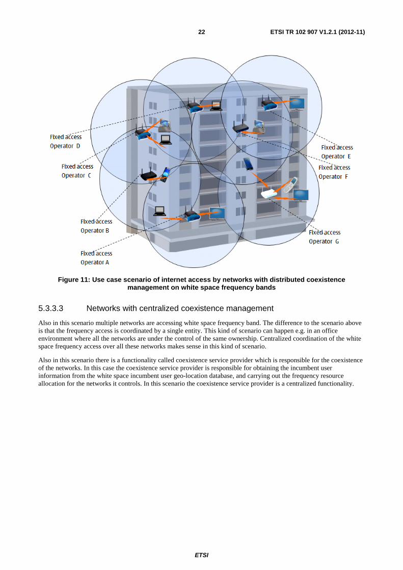
Figure 11: Use case scenario of internet access by networks with distributed coexistence management on white space frequency bands
5.3.3.3 Networks with centralized coexistence management
Also in this scenario multiple networks are accessing white space frequency band. The difference to the scenario above is that the frequency access is coordinated by a single entity. This kind of scenario can happen e.g. in an office environment where all the networks are under the control of the same ownership. Centralized coordination of the white space frequency access over all these networks makes sense in this kind of scenario.
Also in this scenario there is a functionality called coexistence service provider which is responsible for the coexistence of the networks. In this case the coexistence service provider is responsible for obtaining the incumbent user information from the white space incumbent user geo-location database, and carrying out the frequency resource allocation for the networks it controls. In this scenario the coexistence service provider is a centralized functionality.

ETSI
ETSI TR 102 907 V1.2.1 (2012-11) 23
Figure 12: Use case scenario of internet access by networks with centralized coexistence management on white space frequency bands
5.3.3.4 Hybrid of networks with distributed and centralized coexistence management
This scenario combines the above two scenarios, i.e. in the same neighbourhood there are both networks leveraging centralized coexistence management and networks leveraging distributed coexistence management. Examples of where this kind of scenario can happen are combinations of public and private places, like campus areas and shopping malls, where e.g. the "official" local area networks, operating under centralized coexistence management, are complemented by independent access points set up independently by some individuals.
The overall coexistence management in this scenario is distributed, due to the existence of the independent networks. Therefore the coexistence service provider is a distributed functionality in this scenario. The networks with centralized coexistence management will manage their own share of resources in centralized fashion, but they need to cooperate with the other neighbouring networks in order to facilitate overall successful utilization of the white space frequency bands.

ETSI
ETSI TR 102 907 V1.2.1 (2012-11) 24
NOTE: The coverage area of networks with centralized coexistence management is shown in blue, the coverage area of networks with distributed coexistence management is shown in red.
Figure 13: Use case scenario of internet access by hybrid of networks with distributed and
centralized coexistence managements on white space frequency bands
5.3.4 Information Flow
This clause presents information flows for the different alternatives of coexistence management of networks operating on white space frequency bands. As an example these information flows are depicting the case where a new network is set up, or an existing network changes its use of frequency resources (due to changes in interference, evacuation of the band when incumbent user is detected, etc.). The information flows are depicted graphically and described briefly. The information flows have generic actors:
• Non-coexistence enabled node: a node in a network, which does not have coexistence capabilities by itself. An example of such a node is an ordinary end user terminal.
• Coexistence enabled system: a system capable for coexisting with other systems in white spaces, e.g. through commonly agreeing on spectrum usage, through avoiding interference or other similar means. Coexistence enabled system includes a coexistence service provider, and one or more coexistence enabled nodes.
• Coexistence enabled node: a node which has coexistence capabilities, e.g. has access to a coexistence service provider, is able to provide coexistence related information on radio environment to coexistence service provider, and get coexistence configuration information from coexistence service provider. Examples of coexistence enabled nodes in these scenarios are access points and base stations.
• Coexistence service provider: an entity (logical or physical) facilitating an efficient secondary usage of the white space frequency band. It has an access to white space geo-location database service provider to obtain incumbent user information and to coexistence enabled node(s) to obtain information on the radio environment. It has also access and can negotiate with other coexistence service providers of other coexistence enabled systems, which are using the white space spectrum resources in the same area, and can thus interfere with each other. Based on the negotiations the coexistence service provider makes decisions on spectrum use and configures the coexistence enabled nodes accordingly.
ETSI
ETSI TR 102 907 V1.2.1 (2012-11) 25
• White space geo-location database service provider: provides localized information on the incumbent users of the white space frequency bands (spectrum usage etc.).
Networks with distributed coexistence management:
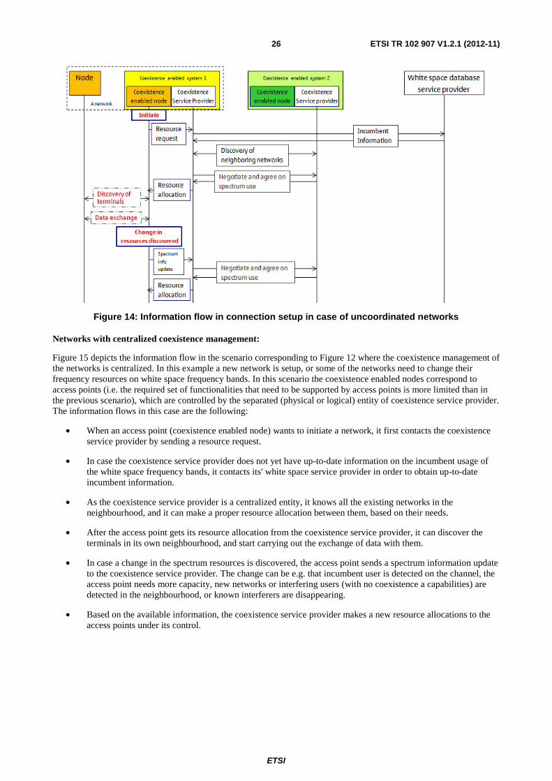
Figure 14 depicts the information flows in the scenario corresponding to Figure 11 where all the networks are independent of each other. In this example a new network is setup, or some of the networks need to change their frequency resources on white space frequency bands. In this scenario, a coexistence enabled system corresponds to an access point (or base station), which supports the functionalities of a coexistence enabled node and coexistence service provider. The information flows are the following:
• An access point (coexistence enabled system 1) is initiating a new network. The first step in the process is that the coexistence enabled node contacts its coexistence service provider with a resource request. Coexistence service provider finds out the incumbent user information in the geographical area of interest. This information is obtained from the white space service provider to which this coexistence enables system is associated with.
• After the localized incumbent information is clarified, the secondary usage of the white space frequency bands in the surroundings needs to be clarified. This discovery process is done by the coexistence service provider.
• After the neighbouring networks have been identified, the associated coexistence service provider(s) will negotiate and agree on the use of the white space spectrum, available for secondary usage in the neighbourhood.
• Based on the negotiation results, the coexistence service provider informs the coexistence enabled node about its resource allocations.
• After the coexistence enabled node obtains its resource allocation information, it can start carrying out its mission using radio access technology it supports, i.e. discover terminals that are in the neighbourhood and carry out the information exchange between mobile terminals and access point on an assigned part of the white space frequency band.
• In the case that some changes related to spectrum resources are discovered, the coexistence enabled node informs its coexistence service provider of the situation. The resource changes can include e.g. that a incumbent user is detected in the utilized channels, the access point needs more capacity, new networks or interfering users are detected in the neighbourhood (these may be only in the neighbourhood of the discovering access point, and thus not part of the coexistence negotiation), or interfering users are disappearing. The coexistence service providers in the neighbourhood re-negotiate the spectrum use based on the updated information, and the coexistence service provider updates the resource allocation of the coexistence enabled node.
ETSI
ETSI TR 102 907 V1.2.1 (2012-11) 26
Figure 14: Information flow in connection setup in case of uncoordinated networks
Networks with centralized coexistence management:
Figure 15 depicts the information flow in the scenario corresponding to Figure 12 where the coexistence management of the networks is centralized. In this example a new network is setup, or some of the networks need to change their frequency resources on white space frequency bands. In this scenario the coexistence enabled nodes correspond to access points (i.e. the required set of functionalities that need to be supported by access points is more limited than in the previous scenario), which are controlled by the separated (physical or logical) entity of coexistence service provider. The information flows in this case are the following:
• When an access point (coexistence enabled node) wants to initiate a network, it first contacts the coexistence service provider by sending a resource request.
• In case the coexistence service provider does not yet have up-to-date information on the incumbent usage of the white space frequency bands, it contacts its' white space service provider in order to obtain up-to-date incumbent information.
• As the coexistence service provider is a centralized entity, it knows all the existing networks in the neighbourhood, and it can make a proper resource allocation between them, based on their needs.
• After the access point gets its resource allocation from the coexistence service provider, it can discover the terminals in its own neighbourhood, and start carrying out the exchange of data with them.
• In case a change in the spectrum resources is discovered, the access point sends a spectrum information update to the coexistence service provider. The change can be e.g. that incumbent user is detected on the channel, the access point needs more capacity, new networks or interfering users (with no coexistence a capabilities) are detected in the neighbourhood, or known interferers are disappearing.
• Based on the available information, the coexistence service provider makes a new resource allocations to the access points under its control.

ETSI
ETSI TR 102 907 V1.2.1 (2012-11) 27
Figure 15: Information flow in connection setup in case of coordinated networks
Hybrid of networks with distributed and centralized coexistence management:
Figure 16 depicts the information flows in the scenario corresponding to Figure 13 where there are both distributed and centralized coexistence management utilized in different networks. In this example a new network (with distributed coexistence management) is setup, or some of the networks need to change their frequency resources on white space frequency bands. The resulting information flows are obviously a combination of the information flows for networks with distributed and centralized coexistence management. The centrally managed networks operate internally as above, but need to cooperate with all the other networks in the neighbourhood. This cooperation happens in distributed fashion, in a similar way as between networks with distributed coexistence management. The information flows in this case are the following:
• All the coexistence enabled systems, irrespective of how many coexistence enables nodes (i.e. access points) they have under their control, are represented by respective coexistence service providers.
• The coexistence service providers take care of all network discoveries and negotiations related activities in order to provide successful coexistence of the systems on white space frequency bands.
• When an access point initiates a network, it activates its coexistence service provider with a resource request to obtain the incumbent user information, which obtains it from its white space geo-location database service provider.
• Next, the coexistence service provider of the initiating coexistence enabled system needs to find out information on the secondary usage of the white space frequency bands. This information is found by discovering the other coexistence service providers in the neighbourhood, which provide the information on the networks under their control.
• After the neighbouring networks have been discovered, the coexistence service providers negotiate and agree on the spectrum use.

ETSI
ETSI TR 102 907 V1.2.1 (2012-11) 28
• After agreeing on the spectrum usage, the access point can discover the terminals in its proximity, and start the data exchange.
• In case a change in the spectrum resources is discovered (the access point needs more capacity, new networks or interfering users are detected in the neighbourhood etc.), the spectrum allocations between networks need to be re-negotiated.
Figure 16: Information flow in connection setup in case of hybrid of uncoordinated and coordinated networks
5.3.5 Derived potential System Requirements
The following system requirements can be drawn from the use case scenarios presented above:
REQ_09: Support of coexistence management
Support coexistence management decision making for different coexistence topologies:
• Distributed
• Centralized
• Hybrid of distributed and centralized
REQ_10: Availability of incumbent information
Reliable incumbent information needs to be available in a straight-forward manner.
REQ_11: Co-existence capabilities
A network operating in the white space frequency bands needs to have capabilities to co-exist with other networks/users in these bands. These capabilities include:
• Capability to discover other secondary users of the spectrum including networks and nodes.
• Capability to negotiate and agree on spectrum usage:
- Includes configuration of the network operation parameters.
• Capability to identify changes in the resources:
- Include configuring network to perform measurements.

ETSI
ETSI TR 102 907 V1.2.1 (2012-11) 29
5.4 Ad-hoc networking over white space frequency bands
5.4.1 General Use Case Description
In this use case the devices (user devices and other devices like access points) communicate with each other to share information, to run joint applications or services, or to execute other similar tasks. The communication happens by forming an ad hoc network operating on white space frequency band. There can be two or more devices in the ad hoc network formed.
This use case can be divided into two scenarios:
• device-to-device connectivity;
• ad-hoc networking.
Communication in White
Space Frequency Bands
Communication in White
Space Frequency Bands
Figure 17: Ad-hoc networking over white space frequency bands
The geo-location from at least one node should be known while for the other devices being in close distance to that node, it may not be necessary to derive an own geo-location. The connection with the White Space geo-location database service provider has to be provided by at least one node and may use other techniques than communication over white space frequency bands.
5.4.2 Stakeholders
• End users: the users of the devices having the need to communicate with other devices.
• White Space geo-location database service provider: in case frequency utilization of frequency bands is available in geo-location databases, this entity provides up-to-date information on incumbent frequency usage.
• Service provider: Provider of a service or application the end users are (possibly) utilizing in the ad hoc networking.

ETSI
ETSI TR 102 907 V1.2.1 (2012-11) 30
5.4.3 Scenarios
5.4.3.1 Device-to-device connectivity
In this case two devices connect in peer-to-peer manner to exchange information between each other. The devices can be similar, e.g. mobile terminals, or different, e.g. a mobile device and an external display or a printer etc. The information communicated between the devices can be e.g. multimedia content, or control information like measurement results shared between the devices. In case the devices have similar capabilities (like two mobile devices), the communication is typically two-way. In case the devices have different capabilities (like a mobile device and a printer), the communication is typically one-way.
In order to ensure the coexistence properties in the white space frequency bands, the pair of devices need to carry out similar operations as in the case of short range wireless access, presented above. These operations include that the white space geo-location database service provider needs to be contacted in order to find out information regarding the incumbent users, and the secondary usage of the white space frequency bands needs to be discovered so that suitable frequency bands can be identified. In practice this requires that at least one of the devices resumes the role of a coexistence service provider, capable of carrying out these coexistence management responsibilities.
Figure 18: Use case on device-to-device connectivity
5.4.3.2 Ad-hoc networking
In this case multiple devices form an ad hoc network to communicate and collaborate with devices in the neighbourhood. As an example the devices can be operating a localized social networking service, which can be maintained by an external service provider.
Setting up the ad hoc network is started in the same way as a device-to-device connection. The difference then is that also other nodes can join in to form the ad-hoc network. Also in this case at least one of the devices has to resume the role of coexistence service provider, responsible for obtaining the incumbent information and secondary spectrum usage information, and negotiating with other networks on the resource allocation.
Figure 19: Ad-hoc networking

ETSI
ETSI TR 102 907 V1.2.1 (2012-11) 31
5.4.3.3 Infrastructure supported ad-hoc networking
In this scenario, the infrastructure supports the creation of ad-hoc networks by providing information and knowledge about policies, available resources, context and profiles. As shown in Figure 20, the users receive information about e.g. the proximity of other users and the available resources (including available white space frequencies) in the neighbourhood from the infrastructure via the base station and thus an ad-hoc network can be created using white space frequency bands. The link between the base station and the terminals can be realized over licensed, unlicensed or white space frequency bands.
Communication in White
Space Frequency Bands
Policies, context, profiles
Policies, context, p
rofiles
Communication in White
Space Frequency Bands
Policies, context, profiles
Policies, context, p
rofiles
Figure 20: Infrastructure supported ad-hoc networking
5.4.4 Information Flow
The information flows for ad hoc networking are similar to those presented for short range wireless access in clause 5.3. All the three coexistence management alternatives, i.e. distributed, centralized, and their hybrid, are possible also in the case of ad hoc networks. The distributed coexistence management is though the most natural management approach. Interpretations of the presented information flows in the case of ad hoc networking are the following:
• In case of distributed coexistence management, in each ad hoc network a mobile node carries out the responsibilities of the coexistence service provider, and is thus responsible for obtaining the incumbent information and agreeing on the spectrum use with other networks. Information flow in Figure 14 is valid in this case. The main difference in the case of ad hoc networking is that due to mobility, the spectrum usage perceived by the network is changing, and therefore the update interval of the spectrum usage information needs to be much higher.
• In case of centralized coexistence management, a node serves as the coexistence service provider for several ad hoc networks in the neighbourhood. This node can mobile or stationary device, e.g. an access point can assume the role of centralized coexistence provider for several ad hoc networks. Information flow in Figure 15 is valid in this case.
• In hybrid case, there exists a mix of the above mentioned deployments in the neighbourhood. Mobile nodes (or stationary nodes for ad hoc networks with centralized coexistence management) serve as the coexistence service providers in the participating coexistence enabled systems. Information flow in Figure 16 is valid in this case.

ETSI
ETSI TR 102 907 V1.2.1 (2012-11) 32
5.4.5 Derived potential System Requirements
The system requirements for this use case includes all the system requirements from clause 5.3.5, namely the requirements REQ_09, REQ_10 and REQ_11.
A further requirement is:
REQ_12: Mobility
Dependent on the specific service case, seamless or lossless mobility needs to be supported. Further on, mobility of an entire ad-hoc network needs also to be supported.
5.5 Combined Ad-hoc networking and wireless access over white space frequency bands
5.5.1 General Use Case Description
This use case presents a combination of the ad-hoc networking use case as described in clause 5.4 with the short range and/or mid-long range wireless access use cases as described in clauses 5.3 and 5.2. Figure 21 shows the combination of an ad-hoc network where one node of the network has also access to a base station. Both the communication inside the ad-hoc network as well as towards the base station is over white space frequency bands. The ad-hoc network may use other radio channels than the radio link towards the base station. Further on, the ad-hoc network may use other radio access technologies than the base station.
Ad-hoc network using whitespace frequency bands
Wireless accessover white space frequency bands BS
Node actingas gateway
Ad-hoc network using whitespace frequency bands
Wireless accessover white space frequency bands BS
Node actingas gateway
Figure 21: Ad-hoc networking combined with mid-/long range wireless access over white space frequency bands
A quite similar scenario is the case of the combination of the ad-hoc network with the short range wireless access as shown in Figure 22.

ETSI
ETSI TR 102 907 V1.2.1 (2012-11) 33
Communication in White
Space Frequency Bands
e.g. Fixed Access …
Communication in White
Space Frequency Bands
e.g. Fixed Access …
Figure 22: Ad-hoc networking combined with short range wireless access over white space frequency bands
These scenarios are characterised by the fact that different wireless links use white space frequency bands and should thus be coordinated. Further on, at least one node has access to infrastructure networks. Thus, assistance information like policies and context information can be provided by the infrastructure.
5.5.2 Stakeholders
• End users: the users of the devices communicating with each other as well as accessing the internet and other similar mobile data services.
• (White Space) Operator: operates and maintains the required infrastructure. It may operate other networks in other frequency bands.
• White Space geo-location database service provider: in case frequency utilization of frequency bands is available in geo-location databases, this entity provides up-to-date information on incumbent frequency usage.
• Service provider: Provider of a service or application the end users are (possibly) utilizing.
5.5.3 Scenarios
For the combination of ad-hoc networking with the short range and/or mid/long ranges wireless access, two scenarios are considered:
• Expanding the coverage of the infrastructure.
• Resolving cases of congested access to the infrastructure.

ETSI
ETSI TR 102 907 V1.2.1 (2012-11) 34
Access Point 2Access Point 1
User 2
User 3
User 1
Access Point 2Access Point 1
User 2
User 3
User 1
Figure 23: Ad-hoc networking combined with wireless access for (a) coverage extensions and (b) resolving cases of congested access to the infrastructure
5.5.3.1 Expanding the coverage of the infrastructure
In this scenario, a device is out of coverage of the infrastructure. An ad-hoc network is created with other devices where at least one of the other devices has access to the infrastructure. The other devices have relaying/forwarding functions in order to route the traffic from the first device towards the internet and vice versa. An example of such a scenario is shown in Figure 23 where the terminal from user 1 is out of coverage of the infrastructure. However, user 1 can create an opportunistic ad-hoc network with user 3 where user 3 relays the traffic from user 1 to the network.
5.5.3.2 Resolving cases of congested access to the infrastructure
In this scenario, one part of the network is congested. As an example, the access point 1 in Figure 23 is congested and thus user 2 will have a very bad QoS when being connected with the access point 1. While user 2 is not able to connect directly to another access point, the situation can however be improved when an opportunistic ad-hoc network is created with user 3 where user 3 relays the traffic from user 2 to the network.
5.5.3.3 Direct device-to-device links in TVWS managed by access points or femto cells
In this scenario, several wireless devices are connected to the internet through an infrastructure device such as an access point or a femtocell. The infrastructure device may have wireless or fixed access to the internet. The wireless devices can, for example, be communicating to an access point over the unlicensed ISM bands, thus representing a standard home or office network setup. They could also be operating in the TVWS bands. Under the management of the access point or femtocell, certain devices may start a direct device-to-device link or point-to-point communication over TVWS frequencies.
In each case, the access point or femtocell will provide bandwidth management for the direct link(s) by querying the geo-location database and by providing TVWS bandwidth management in the case where multiple direct device-to-device links may exist.

ETSI
ETSI TR 102 907 V1.2.1 (2012-11) 35
Access Point
Non-TVWS Communication
Direct Device-to-Device Link Communication over TVWS Frequency
e.g. Fixed Access
Figure 24: Example of a scenario for Managed Direct Device-to-Device Links over TVWS Frequency bands
5.5.4 Information Flow
Figure 25 shows the information flow involved in establishing a direct link between two devices in TVWS.
Step 1: Each device associating or registering with the infrastructure device will send a list of direct link services it offers.
Step 2: The infrastructure device (e.g. base station or access point) will compile the list of services available in the network and periodically broadcast these services to all of the devices in the network.
Step 3a: Based on the service broadcast, device 1 wishes to set up a direct link with device 2 to obtain access to a service offered by device 2 (e.g. Video streaming). It sends a direct link setup request to the infrastructure device.
Step 3b: Alternatively, the infrastructure device determines that device 1 and device 2 would be best suited to communicate through a direct link. It sends a direct link indication to device 1 and waits for direct link acknowledge from this device.
Step 4 and 5: The infrastructure device sends an inquiry to the geo-location database to determine the channels that are currently free of any incumbents and usable for the direct link service being set up.
Step 6: The infrastructure device performs allocation of the TVWS frequency to be used for the direct link. If other ongoing direct links are active, the infrastructure device ensures allocation of the frequency in such a way to ensure interference is properly managed.
Step 7: A direct link indication message is sent to device 2 to inform it of the request for a direct link with device 1, and the TVWS frequency where the direct link will take place.

ETSI
ETSI TR 102 907 V1.2.1 (2012-11) 36
Device 2Infrastructure
Device
Geo-location
DatabaseDevice 1
1. Device Service Announcements
2. Periodic Service
Broadcasts
.
.
.
3a. Direct Link Request
4. Database Inquiry Request
5. Database Inquiry Response
6. TVWS Resource
Allocation
7. Direct Link Indication
9. Direct Link Response
10. Direct Link Communication
8. Direct Link Acknowledge
3b. Direct Link Indication/Acknowledge
Figure 25: Information Flow for managed Direct Device-to-Device Links over TVWS
Step 8: Device 2 will respond with an acknowledgement message if it is able to set up the requested direct link.
Step 9: The infrastructure device sends a direct link response message to device 1 to indicate that the direct link has been established on a specific TVWS frequency. This step corresponds to the start of the direct link.
Step 10: Direct communication between device 1 and device 2 can now take place on the TVWS frequency selected by the infrastructure device.
5.5.5 Derived potential System Requirements
The system requirements for this use case include all the system requirements from clauses 5.2, 5.3 and 5.4 because this use case is a combination of the use cases from those clauses.

ETSI
ETSI TR 102 907 V1.2.1 (2012-11) 37
5.6 Sporadic use of TV white space frequency bands
5.6.1 General Use Case Description
In this use case, TVWS slots are only available sporadically for secondary users, such as for example multi-mode user terminals being able to operate, among other systems, cellular systems in licensed and unlicensed spectrum. The supported unlicensed spectrum is assumed to include TVW, i.e. the 470 MHz to 790 MHz range in Europe/Region 1.
The time-limited switch of a Base Station to operate in unlicensed spectrum (in particular TVWS) is leading to a number of advantages which are further detailed in the scenario descriptions detailed in the subsequent clauses.
NOTE: Similar approaches are discussed for opportunistic relaying in [i.6] and [i.7]).
For the convenience of the reader, an overview of the detailed scenarios presented in the sequel is given here:
• Scenario "Lighter infrastructure deployment through larger cell sizes": If we assume that the probability of a white space in the TV band being available for opportunistic operation of cellular systems, the lower propagation losses experienced by the wireless signals over the TV band allow to increase the cell size of the cellular system. This results in a less dense infrastructure deployment of macro BSs, which reduces CAPEX and OPEX of cellular operators. The system design has to take into account that the TVWS bands are eventually only available for a limited period.
• Scenario "Increased spectral efficiency through reduced propagation loss": Instead of increasing the cell size while keeping the same spectral efficiency, the reduced propagation losses over the TV band can be exploited to switch the link parameters of the communication protocol to a less robust setting, thus yielding a higher spectral efficiency and a higher data throughput. Alternative, the output power of BS/UEs can be reduced thus leading to an increased overall power efficiency.
• Scenario "Increased spectral efficiency through extended macro diversity": Instead of increasing the cell size or modifying the modulation and coding parameters at the physical layer, we can consider a third option where the cellular network opportunistically exploits the TVWS by keeping all link parameters as in a licensed-band deployment at a higher frequency range. In such a case, due to the reduced propagation losses over the TVWS band, the signal emitted by the UE (or optionally by a Relay Node) can be overheard by more distant macro/micro/pico BS and exploited in a cooperative setting to get further macro-diversity gains. This allows the system to improve the performance via cooperative diversity protocols. For the DL, BS cooperation can be exploited for achieving higher QoS.
• Scenario "TVWS Band-Switch in case that incumbent user re-enters": In case that an incumbent user re-enters a band that is currently occupied by a secondary system, a band-switch is performed in case that an alternative TVWS band is available. If such a band is not available, a switch to licensed spectrum is an alternative.
• Scenario "Carrier Aggregation between IMT and TVWS bands": where the TVWS radio resources are used as a Component Carrier (CC) pool and can offer temporary extra radio resources to e.g. LTE systems operating primarily in the IMT bands.
5.6.2 Stakeholders
• User: A user/person living in a rural area or roaming to a rural area where he can be provided with a high data rate wireless connection from TVWS spectrum.
• User terminal: Multi-mode terminal operating both in licensed and TVWS spectrums.

ETSI
ETSI TR 102 907 V1.2.1 (2012-11) 38
• Mobile Network Operator (MNO): This is an operator who provides mobile services e.g. voice and data to its users e.g. when the user terminal is operating in operator licensed spectrums or when operating in TVWS spectrum as secondary/unlicensed usage. In this use case the MNO provides the NW infrastructure in both cases.
5.6.3 Scenario Case Description
5.6.3.1 Lighter infrastructure deployment through larger cell sizes
Due to the improved propagation characteristics in the TVWS bands compared to typical licensed bands, a large cell size is chosen which will lead to a lighter infrastructure deployment and thus to an overall reduced CAPEX/OPEX, as illustrated by Figure 26.
NOTE: The symbols �, �,� indicate decreasing throughput levels, QoS, etc.
Figure 26: Reduced propagation loss in TVWS and thus improved coverage
In the analysis given in [i.7] for a typical example using also the deployment of a relay node, it is observed that for hs = hs = hr = hd = 6,5 m (various combinations of heights (hs, hr, hd) of S (Source), R (Relay), and D (Destination) are used) it is possible to transmit over a wireless link at 470 MHz with d = 200 m by getting the same performance as a legacy wireless link at 2 GHz with d = 100 m. In this setup, the communication distance can be increased twofold by keeping the same QoS.
In case that the incumbent user reappears, the BS accessing to TVWS typically need to switch to a different TVWS frequency band (if available) or switch to the licensed spectrum (for example in the 2 GHz band). In the latter case, the coverage is reduced - in order to still maintain the coverage of the cell, either a lower QoS needs to be tolerated at the cell-edges or relay nodes may be deployed in order to attenuate the corresponding effects.
5.6.3.2 Increased spectral efficiency through reduced propagation loss
Due to the improved propagation characteristics in the TVWS bands compared to typical other licensed bands, a possible deployment choice is to keep a cell size as it is the case for the licensed band deployment. The following advantages are observed:
1) Due to the improved propagation characteristics in the TVWS bands, a higher QoS is achieved within the given cell (see Figure 27). However, those propagation characteristics may also increase interference issues which require an adequate handling (e.g. suitable frequency reuse-factor for TVWS, power management, etc.).
2) Due to the improved propagation characteristics in the TVWS bands, an identical QoS is achieved within the given cell at a lower BS/UE output power level. The inherent power consumption can be reduced.
3) A hybrid solution of item #1 and #2 is possible, i.e. a moderate reduction of the BS output power levels combined with a moderate improvement of the QoS.
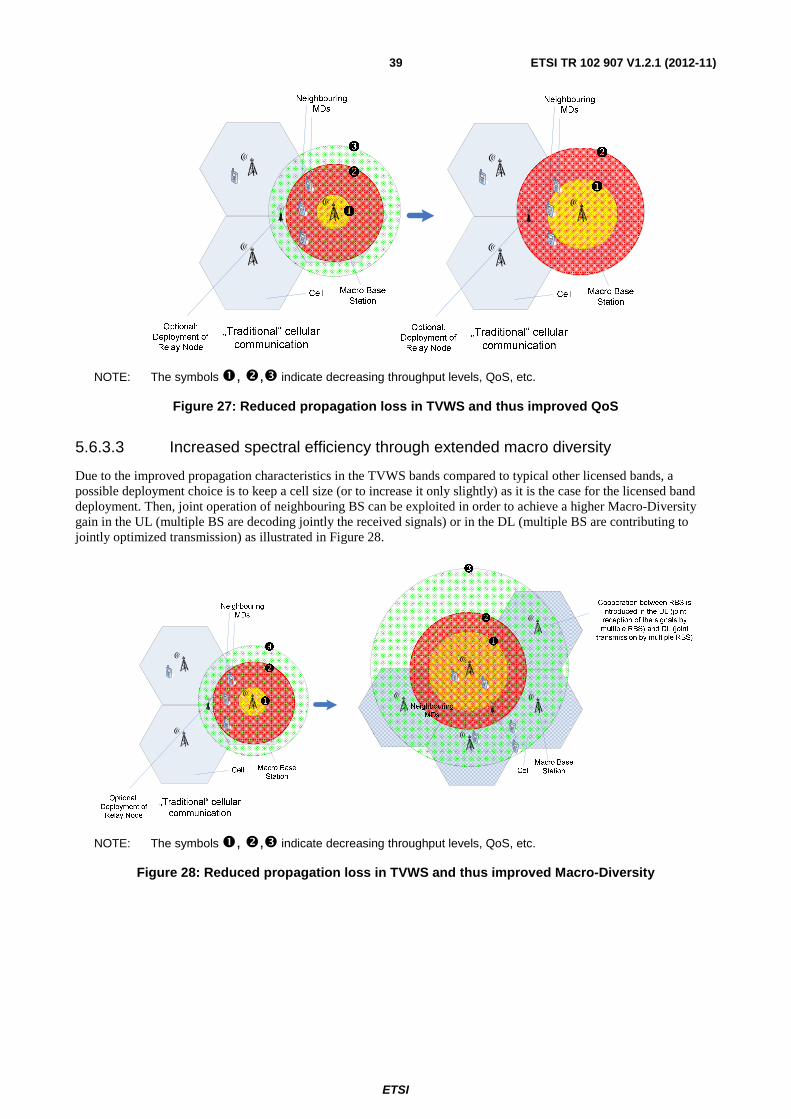
ETSI
ETSI TR 102 907 V1.2.1 (2012-11) 39
NOTE: The symbols �, �,� indicate decreasing throughput levels, QoS, etc.
Figure 27: Reduced propagation loss in TVWS and thus improved QoS
5.6.3.3 Increased spectral efficiency through extended macro diversity
Due to the improved propagation characteristics in the TVWS bands compared to typical other licensed bands, a possible deployment choice is to keep a cell size (or to increase it only slightly) as it is the case for the licensed band deployment. Then, joint operation of neighbouring BS can be exploited in order to achieve a higher Macro-Diversity gain in the UL (multiple BS are decoding jointly the received signals) or in the DL (multiple BS are contributing to jointly optimized transmission) as illustrated in Figure 28.
NOTE: The symbols �, �,� indicate decreasing throughput levels, QoS, etc.
Figure 28: Reduced propagation loss in TVWS and thus improved Macro-Diversity

ETSI
ETSI TR 102 907 V1.2.1 (2012-11) 40
5.6.3.4 TVWS Band-Switch in case that incumbent user re-enters
The TVWS usage rules vary over the geographical regions. Typically, when an incumbent system arrives, the corresponding band is no longer available for opportunistic spectrum access by secondary systems. Also, a guard band is introduced as it is illustrated in Figure 29 for the example of an FCC TVWS usage context.
Figure 29: Arrival of Primary user in TV White Space Framework, Example given in alignment to FCC ruling (the Guard Band insertion follows FCC rules, see [i.3])
In this scenario, it is suggested that the secondary user switches to another TVWS channel that is still available for opportunistic access - if such a channel is available. Otherwise, the secondary user is assumed to switch to operate in a suitable licensed band.
5.6.3.5 Carrier Aggregation between IMT bands and TV WS band
Carrier Aggregation is one of the most distinct features of 4G systems such as LTE Advanced, which is being standardized in 3GPP as part of LTE Release 10. It allows the support of wider transmission bandwidths: up to 100 MHz by aggregating two or more component carriers (CC), up to 5 CCs. An LTE advanced terminal may simultaneously receive and transmit signals on one or multiple Component Carriers depending on its capabilities and it is possible to aggregate a different number of component carriers of possibly different bandwidths in the UL and the DL.
3GPP is currently considering the 3 spectrum scenarios (refer to Figure 30):
• Intra-band contiguous Carrier aggregation: This is the case where multiple available CCs are adjacent to each other and allows aggregating contiguous bandwidth wider than 20 MHz.
• Intra-band non-contiguous carrier Aggregation: This is the case where multiple CCs belong to the same bands and are used in a non-contiguous manner.
• Inter-band non-contiguous carrier aggregation: This is the case where multiple CCs belong to different bands.
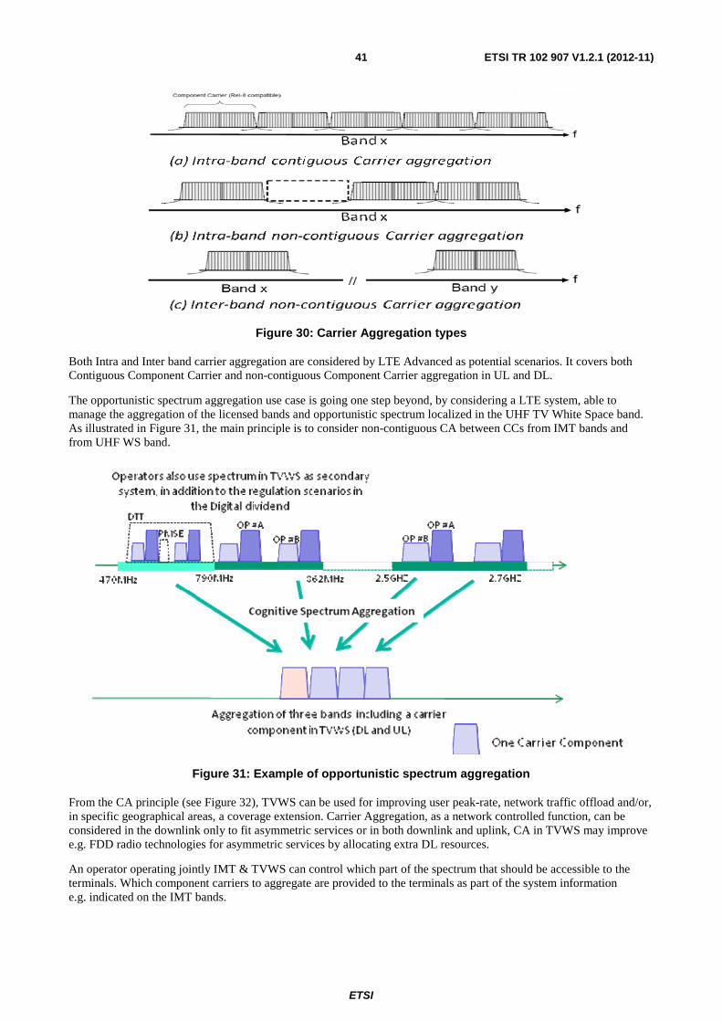
ETSI
ETSI TR 102 907 V1.2.1 (2012-11) 41
Figure 30: Carrier Aggregation types
Both Intra and Inter band carrier aggregation are considered by LTE Advanced as potential scenarios. It covers both Contiguous Component Carrier and non-contiguous Component Carrier aggregation in UL and DL.
The opportunistic spectrum aggregation use case is going one step beyond, by considering a LTE system, able to manage the aggregation of the licensed bands and opportunistic spectrum localized in the UHF TV White Space band. As illustrated in Figure 31, the main principle is to consider non-contiguous CA between CCs from IMT bands and from UHF WS band.
Figure 31: Example of opportunistic spectrum aggregation
From the CA principle (see Figure 32), TVWS can be used for improving user peak-rate, network traffic offload and/or, in specific geographical areas, a coverage extension. Carrier Aggregation, as a network controlled function, can be considered in the downlink only to fit asymmetric services or in both downlink and uplink, CA in TVWS may improve e.g. FDD radio technologies for asymmetric services by allocating extra DL resources.
An operator operating jointly IMT & TVWS can control which part of the spectrum that should be accessible to the terminals. Which component carriers to aggregate are provided to the terminals as part of the system information e.g. indicated on the IMT bands.
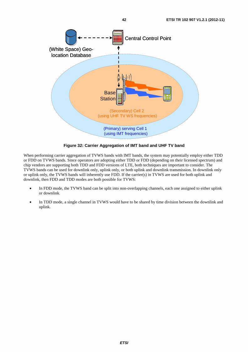
ETSI
ETSI TR 102 907 V1.2.1 (2012-11) 42
(Primary) serving Cell 1 (using IMT frequencies)
(Secondary) Cell 2 (using UHF TV WS frequencies)
Central Control Point
(White Space) Geo-location Database
BaseStation
(Primary) serving Cell 1 (using IMT frequencies)
(Secondary) Cell 2 (using UHF TV WS frequencies)
Central Control Point
(White Space) Geo-location Database
BaseStation
Figure 32: Carrier Aggregation of IMT band and UHF TV band
When performing carrier aggregation of TVWS bands with IMT bands, the system may potentially employ either TDD or FDD on TVWS bands. Since operators are adopting either TDD or FDD (depending on their licensed spectrum) and chip vendors are supporting both TDD and FDD versions of LTE, both techniques are important to consider. The TVWS bands can be used for downlink only, uplink only, or both uplink and downlink transmission. In downlink only or uplink only, the TVWS bands will inherently use FDD. If the carrier(s) in TVWS are used for both uplink and downlink, then FDD and TDD modes are both possible for TVWS:
• In FDD mode, the TVWS band can be split into non-overlapping channels, each one assigned to either uplink or downlink.
• In TDD mode, a single channel in TVWS would have to be shared by time division between the downlink and uplink.

ETSI
ETSI TR 102 907 V1.2.1 (2012-11) 43
5.6.4 Information Flow
5.6.4.1 Adding a New RAT Component Carrier into UHF TVWS Band
Figure 33: Adding a new RAT component carrier into the UHF TVWS band
Step 1: The Base Station sends TVWS Allocation Request (including the location of base station and possible early sensing measurements in the TV WS bands) to the central control point to ask for allocation of the TVWS resources.
Step 2: The central control point inquires the geo-location database whether there are available TVWS frequency bands at the location of the base station.
Step 3: The central control point makes a decision on the TVWS frequency allocation to the Base Station based on the information retrieved from the database and its knowledge of the neighbouring radio usage e.g. the central control point will manage interference between neighbour cells within the same Network.
Step 4: If there is available TVWS frequency existing at the location of Base Station, the Central Control Point sends TVWS Allocation Response which includes the information of allocated TVWS to the base station. Other configuration parameters (e.g. candidate frequency bands information, transmission power restricted by regulation) may be sent to base station as well. Otherwise, the central control point will notify the Base Station that no TVWS is available at its location.
Step 5: The Base Station makes decision on the TV band spectrum used as component carrier(s) to perform carrier aggregation according to the unoccupied TVWS indicated by the Central Control Point. Base station configures itself correspondingly.
Step 6: The Base Station sends BS Configuration Update message including the updated configuration parameters to the Central Control Point. The Central Control Point responds with BS Configuration Update Ack message to acknowledge that it successfully updated the configuration data.
Step 7: The Base Station notifies the UE about the carrier aggregation status, e.g. through the system information in IMT band. For the connected mode UE, the Base Station may redirect it to the additional TV band to offload the traffic from IMT band.
NOTE: In order to avoid frequent handover, a component carrier in UHF TV band is not suitable to be chosen as primary cell since TVWS may become unavailable when the primary user appears. In other words, it is better for the Base Station to select a component carrier in IMT band as the primary cell.
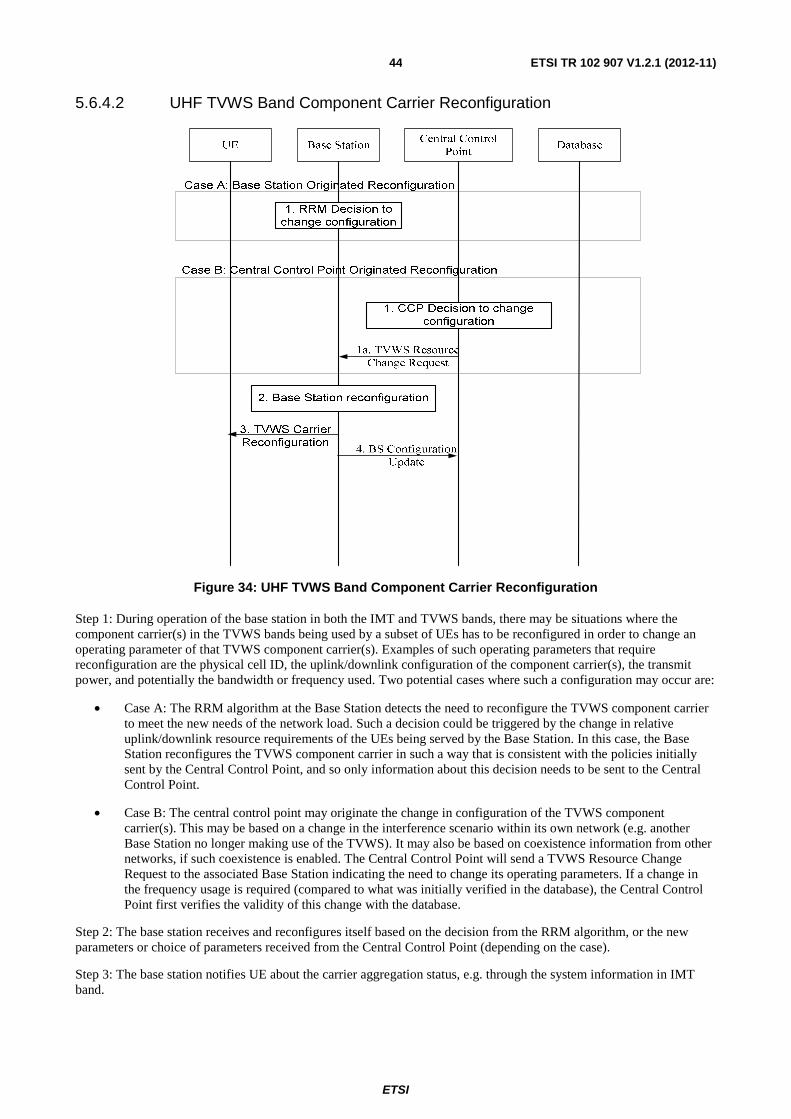
ETSI
ETSI TR 102 907 V1.2.1 (2012-11) 44
5.6.4.2 UHF TVWS Band Component Carrier Reconfiguration
Figure 34: UHF TVWS Band Component Carrier Reconfiguration
Step 1: During operation of the base station in both the IMT and TVWS bands, there may be situations where the component carrier(s) in the TVWS bands being used by a subset of UEs has to be reconfigured in order to change an operating parameter of that TVWS component carrier(s). Examples of such operating parameters that require reconfiguration are the physical cell ID, the uplink/downlink configuration of the component carrier(s), the transmit power, and potentially the bandwidth or frequency used. Two potential cases where such a configuration may occur are:
• Case A: The RRM algorithm at the Base Station detects the need to reconfigure the TVWS component carrier to meet the new needs of the network load. Such a decision could be triggered by the change in relative uplink/downlink resource requirements of the UEs being served by the Base Station. In this case, the Base Station reconfigures the TVWS component carrier in such a way that is consistent with the policies initially sent by the Central Control Point, and so only information about this decision needs to be sent to the Central Control Point.
• Case B: The central control point may originate the change in configuration of the TVWS component carrier(s). This may be based on a change in the interference scenario within its own network (e.g. another Base Station no longer making use of the TVWS). It may also be based on coexistence information from other networks, if such coexistence is enabled. The Central Control Point will send a TVWS Resource Change Request to the associated Base Station indicating the need to change its operating parameters. If a change in the frequency usage is required (compared to what was initially verified in the database), the Central Control Point first verifies the validity of this change with the database.
Step 2: The base station receives and reconfigures itself based on the decision from the RRM algorithm, or the new parameters or choice of parameters received from the Central Control Point (depending on the case).
Step 3: The base station notifies UE about the carrier aggregation status, e.g. through the system information in IMT band.

ETSI
ETSI TR 102 907 V1.2.1 (2012-11) 45
Step 4: The base station notifies the Central Control Point of the reconfiguration (or the final choice of configuration made) so that the Central Control Point can use this information to continue to provide proper operation and interference avoidance within its own network.
NOTE: Step 4 can be performed before Step 3.
5.6.4.3 Incumbent protection
Figure 35: Incumbent protection
Step 1: Incumbent user (e.g. TV tower, wireless microphone) registers to the database at a certain period such as one day or several hours in advance of using the UHF TV band. The location of the incumbent user at an acceptable accuracy (e.g. ≤ 50 meters) and occupied TV channels should be informed to the database at this step.
Step 2: Database re-calculates the available TVWS at the location of the incumbent user. Normally, there are two ways for central control point to acquire updated spectrum usage status information. 1) Database notifies the central control point about the change of the available TVWS at those areas directly. 2) Central control point accesses to database to obtain the latest information periodically, e.g. less than one day.
Step 3: The central control point makes decision on the TVWS frequency usage modification to the base station based on the information retrieved from the database and its knowledge of the neighbouring radio usage e.g. the central control point will manage interference between neighbour cells within the same Networks. Then the central control point notifies the related base stations to release corresponding TVWS resources.
Step 4: Base station has to stop allocating resources and cancel the secondary cell in the current TV WS carrier component. Base Station notifies UE about the carrier aggregation status, e.g. through the system information in IMT band.
Step 5: Base station makes decision on the TV band spectrum used as carrier component(s) BS configures itself to stop transmission in the carrier component of TV band spectrum for incumbent protection.

ETSI
ETSI TR 102 907 V1.2.1 (2012-11) 46
Step 6: Base station sends BS Configuration Update message including the updated configuration parameters to the central control point. The central control point responds with BS Configuration Update Ack message to acknowledge that it successfully updated the configuration data.
NOTE 1: Information flows given here only address what happens while the UE is in RRC_Connected mode of operation (where carrier aggregation can actually take place).
NOTE 2: In carrier aggregation scenario, HO is performed under condition that primary cell has been changed. As mentioned in the previous clause, primary cell is always selected from the IMT band. In other words, frequent HO will not occur even if the incumbent user appears at the UHF TV band. Therefore, Base Station only needs to inform related UE about the updated carrier aggregation status. For connected mode UE, base station will inform it to delete secondary cell of the releasing TV band. For IDLE mode, UE has only to camp on a cell in the IMT band.
5.6.5 Derived potential system requirements
The system requirements REQ_02, REQ_03, REQ_04, REQ_05 and REQ_06 are also applicable for this use case.
A further derived requirement to be considered is:
REQ_13: Base station based management of TVWS access
It is assumed that a BS accessing TVWS will apply a combination of (distributed/centralized) sensing and geolocation data-base access (containing information of actual/intended spectrum usage by incumbent users) in order to determine available and suitable TVWS bands for the operation of cellular systems. A corresponding "TVWS Access Management" function will deal with the acquisition of the required information and the corresponding configuration of the concerned UEs.
5.7 Backhaul link using TV white space frequency bands
5.7.1 General Use Case Description
In current mobile networks, there are many access points which have different capabilities, e.g. they can support different coverage. These access points can be connected with wireless backhaul link. In 3GPP LTE for example, the backhaul link between the base station and relay is wireless. These access points have the following features:
• directed antenna configuration;
• location fixed;
• do not limit to Power consumption;
• Soft and Hardware are scalable with lower cost.
The wireless backhaul link operated on the TVWS can obtain the following advantages:
• improve the access link capacity;
• supporting the existing commercial terminals;
• providing a simple wireless environment;
• providing a better channel quality because of the good propagation performance of the TVWS bands;
• improve the capacity of the backhaul link;
• supporting the sensing capability and scalable spectrum bands with lower cost.
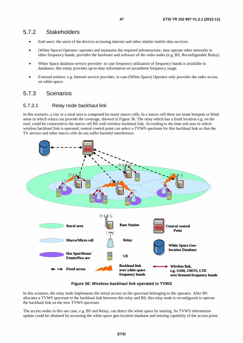
ETSI
ETSI TR 102 907 V1.2.1 (2012-11) 47
5.7.2 Stakeholders
• End users: the users of the devices accessing internet and other similar mobile data services.
• (White Space) Operator: operates and maintains the required infrastructure; may operate other networks in other frequency bands; provides the hardware and software of the radio nodes (e.g. BS, Reconfigurable Relay).
• White Space database service provider: in case frequency utilization of frequency bands is available in databases, this entity provides up-to-date information on incumbent frequency usage.
• External entities: e.g. Internet service provider, in case (White Space) Operator only provides the radio access on white space.
5.7.3 Scenarios
5.7.3.1 Relay node backhaul link
In this scenario, a city or a rural area is composed by many macro cells. In a macro cell there are some hotspots or blind areas in which relays can provide the coverage, showed in Figure 36. The relay which has a fixed location e.g. on the roof, could be connected to the macro cell BS with wireless backhaul link. According to the time and area in which wireless backhaul link is operated, central control point can select a TVWS spectrum for this backhaul link so that the TV service and other macro cells do not suffer harmful interference.
Rural area
Marco/Micro cell
Base Station
Relay
Backhaul linkover white spacefrequency bands
Central control Point
White Space Geo-location Database
Hot Spot/Home/Femto/Pico are
Fixed accessWireless link, e.g. GSM, UMTS, LTEover licensed frequency bands
UE
Rural area
Marco/Micro cell
Base Station
Relay
Backhaul linkover white spacefrequency bands
Central control Point
White Space Geo-location Database
Hot Spot/Home/Femto/Pico are
Fixed accessWireless link, e.g. GSM, UMTS, LTEover licensed frequency bands
UE
Figure 36: Wireless backhaul link operated in TVWS
In this scenario, the relay node implements the initial access on the spectrum belonging to the operator. After BS allocates a TVWS spectrum to the backhaul link between this relay and BS, this relay node is reconfigured to operate the backhaul link on the new TVWS spectrum.
The access nodes in this use case, e.g. BS and Relay, can detect the white space by sensing. So TVWS information update could be obtained by accessing the white space geo-location database and sensing capability of the access point.

ETSI
ETSI TR 102 907 V1.2.1 (2012-11) 48
5.7.4 Information Flow
5.7.4.1 Information Flow for Backhaul Link Initial Work Procedure
Relay BSCentral
Control PointTV Database
2.Power on
4. TVWS Resource
Request
5.TVWS Resource
allocation Decision
6. TVWS Allocation
Response
7. Backhaul link resource allocation
9a. Reconfiguration
Information Update
9b. Reconfiguration
Information Update Ack
10. Update the
Information of
TVWS
1. Obtain and Maintain the TVWS information
3a. Capability
Report
8. Backhaul link Reconfiguration
3b. Capability
Report ACK
Figure 37: Procedure of TVWS resource allocation for initial backhaul link
Step 1: The Central Control Point (CCP) can obtain the TVWS information from the white space geo-location database periodically or triggered by the change of the information. CCP can also update the TVWS information when it receives the spectrum sensing results from BS. CCP can exchange the TVWS information with BS.
Step 2: Relay node is power on.
Step 3: Relay node reports its capability information to BS on the spectrum belonging to the operator and BS responds with Capability Report Ack message to acknowledge that it has received the relay's capability information successfully.
Step 4: BS sends a TVWS resource request to CCP for the Backhaul link.
Step 5: According to the TVWS information which CCP obtains, CCP determines the policy of resource allocation including the TVWS allocation. The CCP may need to coordinate the resource between different BSs.
Step 6: CCP sends the policy of resource allocation to the BSs which need to change the spectrum resource for the backhaul link.
Step 7: BS allocates the resource including TVWS resource based on the policy from CCP to the backhaul link which need new spectrum resource or change the spectrum resource due to resource coordination decision.
Step 8: The BS and the Relay connected by the backhaul link which is operated on a new spectrum are reconfigured.
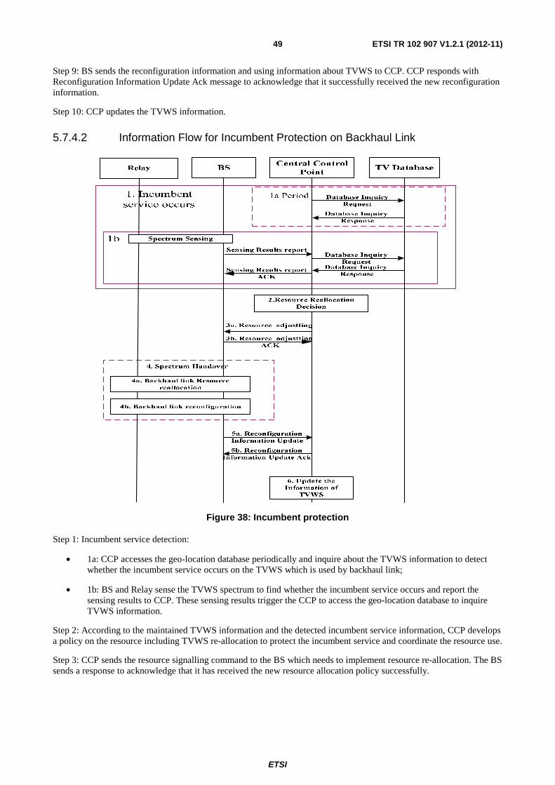
ETSI
ETSI TR 102 907 V1.2.1 (2012-11) 49
Step 9: BS sends the reconfiguration information and using information about TVWS to CCP. CCP responds with Reconfiguration Information Update Ack message to acknowledge that it successfully received the new reconfiguration information.
Step 10: CCP updates the TVWS information.
5.7.4.2 Information Flow for Incumbent Protection on Backhaul Link
Figure 38: Incumbent protection
Step 1: Incumbent service detection:
• 1a: CCP accesses the geo-location database periodically and inquire about the TVWS information to detect whether the incumbent service occurs on the TVWS which is used by backhaul link;
• 1b: BS and Relay sense the TVWS spectrum to find whether the incumbent service occurs and report the sensing results to CCP. These sensing results trigger the CCP to access the geo-location database to inquire TVWS information.
Step 2: According to the maintained TVWS information and the detected incumbent service information, CCP develops a policy on the resource including TVWS re-allocation to protect the incumbent service and coordinate the resource use.
Step 3: CCP sends the resource signalling command to the BS which needs to implement resource re-allocation. The BS sends a response to acknowledge that it has received the new resource allocation policy successfully.

ETSI
ETSI TR 102 907 V1.2.1 (2012-11) 50
Step 4: The BS and the Relay connected by the backhaul link which is operated on a new spectrum perform the spectrum handover:
• 4a: BS allocates the resource including TVWS resource based on the policy from CCP to the backhaul link which need new spectrum resource or change the spectrum resource due to resource coordination decision;
• 4b: The BS and the Relay connected by the backhaul link which is operated on a new spectrum are reconfigured.
Step 5: BS sends the reconfiguration information and using information about TVWS to CCP. CCP responds with Reconfiguration Information Update Ack message to acknowledge that it has received the new reconfiguration information successfully.
Step 6: CCP updates the TVWS information.
5.7.5 Derived potential System Requirements
The system requirements REQ_01, REQ_02, REQ_03, REQ_04, REQ_05, REQ_06, REQ_07, REQ_08 and REQ_13 are also applicable for this use case.
Further derived requirement to be considered are:
REQ_14: Reconfigurable relay
In a scenario with a relay at a fixed location providing connectivity between the base station and the end user, which can operate in licensed and TVWS spectrums, the relay as well as the base station should have the capability of detecting the incumbent signal. Further on, the relay node should support radio technology reconfiguration.
REQ_15: Initialize the backhaul link
In a scenario with a relay backhaul link, the backhaul link initially operates on the spectrum belonging to the operator. After the base station allocates a TVWS spectrum to the backhaul link, the relay should be reconfigured to operate on the new TVWS spectrum.
REQ_16: Backhaul link protection
It is important to ensure a stable connection for the backhaul link when the incumbent signal emerges.
5.8 MBMS operating in TV white space frequency bands
5.8.1 General Use Case Description
Broadcasting services are widely used when transmitting the same content to a group of users at the same time in many telecommunication systems (e.g. UMTS/LTE). When performing broadcasting services, specific radio resources need to be reserved. Moreover, with the increased categories of the applications, especially some broadband applications, e.g. live TV program broadcasting, the radio resources will become quite insufficient. Therefore, the utilization of TVWS to transmit broadcasting services could meet the requirements for more radio resources. To be simplified, this use case takes the 3GPP LTE Multimedia Broadcast Multicast Service (MBMS) for example. However, other broadcasting services (e.g. UMTS) are not excluded.
5.8.2 Stakeholders
• Users: the users of multi-mode terminals operating both in licensed and TVWS spectrums.
• Mobile Network Operator (MNO): this is an operator who provides mobile services to its users e.g. when the user terminal is operating in operator licensed spectrums or when operating in TVWS spectrum as secondary/unlicensed usage.
• White Space database service provider: in case frequency utilization of frequency bands is available in databases, this entity provides up-to-date information on incumbent frequency usage.

ETSI
ETSI TR 102 907 V1.2.1 (2012-11) 51
• MBMS content provider: operator or third party companies which provide broadcasting services content, e.g. live TV program broadcasting, to the User terminals.
5.8.3 Scenarios
5.8.3.1 LTE MBMS in TV white space frequency bands
In LTE, the MBSFN (Multimedia Broadcast multicast service Single Frequency Network) mode is realised in the manner that a group cells transmit identical waveforms with the same frequency at the same time in order to promote the frequency efficiency. Those group cells constitute an MBSFN area. A central control entity called MCE (Multi-cell/multicast Coordination Entity) is used for admission control and allocation of the radio resource used by all the eNBs in the same MBSFN area to ensure the MBSFN transmission. Figure 39 illustrates the scenario broadcasting services operating in TVWS frequency bands.
Figure 39: Broadcasting services over white space frequency bands
This scenario is quite similar to network centric management of TV White Space described in clause 5.2. The MCE acts as a central control point and manage TVWS resources allocation to the whole MBSFN area. Since MCE has the admission control as well, it is aware of the load condition of the whole MBSFN area. Without applying TVWS frequency bands for broadcasting services, MCE will refuse to establish the MBMS radio bearers if the radio resources are not sufficient in the MBSFN area it controls. Otherwise, as the central control point, MCE connects to a database to get the information of TVWS spectrum usage status and decides whether suitable TVWS frequency bands can be used for transmitting broadcasting services in the whole MBSFN area. Since all the eNBs in the same MBSFN area share the same frequency resource, no negotiation is needed within MBSFN area. However, MCE may control the interference between different MBSFN areas under its control. The base station in this scenario may be enhanced with the capability of sensing TVWS spectrums and reporting the sensing result to the MCE. In this scenario, TVWS frequency bands are only used to transmit MBMS service data; MBMS signalling (e.g. MBMS service announcement) is still carried by LTE bands.

ETSI
ETSI TR 102 907 V1.2.1 (2012-11) 52
5.8.4 Information Flow
Figure 40: LTE MBMS in TV white space frequency bands
Step 1: MME sends MBMS session start request message to the MCE(s) controlling eNBs in the targeted MBSFN area. The message includes QoS parameters of the MBMS session.
Step 2: According to the QoS parameters (e.g. MBR) received in the step 1, MCE checks whether the radio resources are sufficient for the establishment of new MBMS service(s) in the area it controls. If not, MCE decides to access to TVWS frequency bands in the following steps.
Step 3: MCE inquires database whether there are available TVWS frequency bands at the location of the MBSFN Area.
Step 4: MCE makes decision on the TVWS radio resource allocation according to the information retrieved in step 3. The MBMS service can be transmitted on TVWS only if the same unoccupied TVWS frequency bands are available in the whole MBSFN Area, otherwise, MCE does not forward any message to the involved eNBs at later stage and MCE notifies MME about the unsuccessful establishment of the MBMS session by sending MBMS Session Start Response message. If MCE controls multiple MBSFN Areas, the interference between adjacent MBSFN Areas should be considered when determining the allocation of TVWS radio resource. TVWS radio resource applies only for the MBMS data transmission (MTCH), MBMS signalling (BCCH & MCCH) still uses IMT bands in order to align with the legacy LTE network.
Step 5: If available TVWS frequency existing at the location of the MBSFN Area, MME sends MBSFN Area Configuration Command which includes the information of allocated TVWS to the corresponding eNBs in the MBSFN Area. Other configuration parameters (e.g. candidate frequency bands information, transmission power restricted by regulation) may be sent to MBSFN area as well.
Step 6: eNBs in MBSFN area configure themselves according to the parameters indicated in MBSFN Area Configuration Command.
Step 7: eNBs in MBSFN area sends MBSFN Area Configuration Response to MCE.
Step 8: MCE sends MBMS Session Start Response to MME. This message can be sent after Step 4.
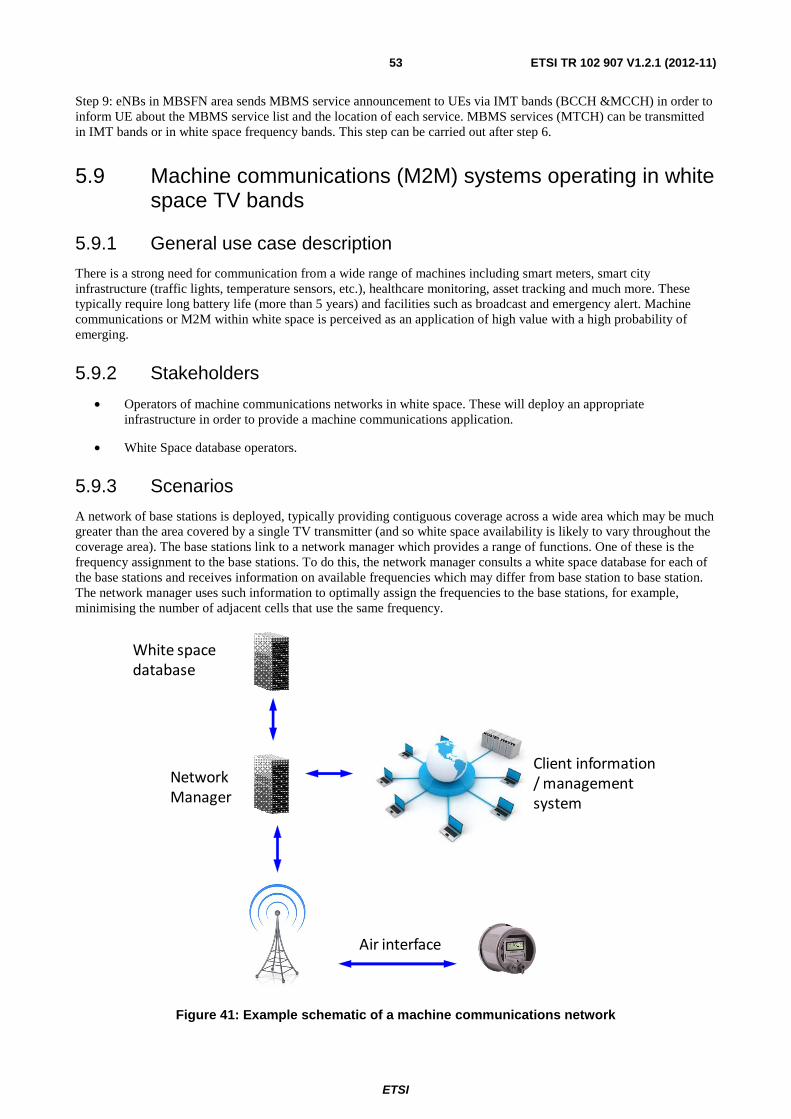
ETSI
ETSI TR 102 907 V1.2.1 (2012-11) 53
Step 9: eNBs in MBSFN area sends MBMS service announcement to UEs via IMT bands (BCCH &MCCH) in order to inform UE about the MBMS service list and the location of each service. MBMS services (MTCH) can be transmitted in IMT bands or in white space frequency bands. This step can be carried out after step 6.
5.9 Machine communications (M2M) systems operating in white space TV bands
5.9.1 General use case description
There is a strong need for communication from a wide range of machines including smart meters, smart city infrastructure (traffic lights, temperature sensors, etc.), healthcare monitoring, asset tracking and much more. These typically require long battery life (more than 5 years) and facilities such as broadcast and emergency alert. Machine communications or M2M within white space is perceived as an application of high value with a high probability of emerging.
5.9.2 Stakeholders
• Operators of machine communications networks in white space. These will deploy an appropriate infrastructure in order to provide a machine communications application.
• White Space database operators.
5.9.3 Scenarios
A network of base stations is deployed, typically providing contiguous coverage across a wide area which may be much greater than the area covered by a single TV transmitter (and so white space availability is likely to vary throughout the coverage area). The base stations link to a network manager which provides a range of functions. One of these is the frequency assignment to the base stations. To do this, the network manager consults a white space database for each of the base stations and receives information on available frequencies which may differ from base station to base station. The network manager uses such information to optimally assign the frequencies to the base stations, for example, minimising the number of adjacent cells that use the same frequency.
Network
Manager
Air interface
White space
database
Client information
/ management
system
Figure 41: Example schematic of a machine communications network

ETSI
ETSI TR 102 907 V1.2.1 (2012-11) 54
In Figure 41 terminals, for example embedded within smart meters, send messages such as current meter readings over the machine communications air interface to base stations nearby. These base stations connect to a network manager which in turn accesses a white space database to obtain frequency availability. The network manager connects also to client information/management systems run by end customers (e.g. electricity providers or automotive manufacturers) to enable information exchange between them and the terminals.
Base stations transmit only on frequencies within the white space bands that they have been authorised to use. Terminals scan across the white space band to discover transmissions from the base stations, decode these transmissions and act in accordance with instructions received from them. The terminals behave as "slaves" with regard to white space spectrum allocations.
Sensing is not used to determine which channels are free for use - this is based solely on information provided by the white space database. However, the network manager may conclude that certain frequencies in certain locations lead to higher than expected error rates and may therefore prefer not to use these frequencies.
5.9.4 Information flow
The information flow is shown below.
Figure 42: Example information flow
• The network manager consults the white space database to obtain frequency availability for each base station. This may be repeated periodically, for example when allocations time-expire.
• The white space database returns a list of available frequencies at each base station.
• The network manager processes this information and assign the appropriate frequencies to each base station.
• The base station transmits on these frequencies and this transmission is detected by the terminals which respond according to instructions received from the base station.
Terminal White space database
Request white space availability
Provide white space availability
Base station Network Manager
Frequency allocation
Broadcast channel availability
Exchange of data

ETSI
ETSI TR 102 907 V1.2.1 (2012-11) 55
5.9.5 Derived potential System Requirements
The system requirements REQ_01, REQ_02, REQ_04, REQ_05 and REQ_11 are also applicable for this use case.
Further derived requirement to be considered is:
REQ_17: Low power operation
It should be possible for terminal devices to operate with extended sleep modes but be able to quickly and easily re-acquire the network on awakening.
6 Potential System Requirements This clause summarises the possible system requirements, which have been derived from the use cases as described above.
REQ_01: Incumbent user protection
The impacts on TV receiving signal should be managed below an acceptable level. How well the incumbent user is protected determines the possibility whether the spectrum owners are willing to share their white space or not.
There are two phases for incumbent user protection:
1) secondary user has the capability to discover TVWS which is not occupied by incumbent user;
2) secondary user has to free the spectrum to incumbent user in a reasonable time after it appears.
REQ_02: Geo-location Database management
It should be possible to get information on incumbent user(s) and optionally also on secondary user(s) of the TVWS frequency bands from a reliable and secure geo-location database. The usage of TVWS frequency bands may need to be registered with the geo-location database. The operation of the geo-location database can be done by a third party service provider as e.g. described in [i.5].
REQ_03: Base Station based sensing
The market may be sensitive to the terminal price, so it would be beneficial that using white space would not add too much complexity on terminals. Terminals may not even support cognitive capability but while being SDR capable e.g. terminals can adapt and operate on new frequency bands and thus operate in TVWS. Cognitive capabilities may not be required for terminals; in this case the base stations are able to detect the incumbent signal (geo-location database plus sensing) without assistance from mobiles.
REQ_04: Centralized spectrum allocation
In order to avoid the interference between different cells a central point is provided with the control and allocate available TVWS spectrum. Every involved base stations operating TVWS have to connect to the central point to negotiate available TVWS frequency resource before using it. The central point has the capability to reduce the interference between neighbour cells by allocating different TVWS frequency resources to them or configures the base stations with reasonable transmission power.
REQ_05: Fast initial Access to network
Network provides the terminal with the information about the available TVWS frequency bands. For example, a terminal accesses to a certain RAT such as HSPA operating in licensed band to obtain the information through in-band CPC. As a result, there is no need for the terminal to scan large frequency bands to find available TVWS resource.
REQ_06: Seamless handover within TVWS spectrum
While incumbent user appears, the QoS of the incumbent user as well as the secondary user should be insured. Primary user protection mentioned in the previous clause is applied for granting the QoS of incumbent user. Furthermore, as said white space in this case is mainly used to solve the coverage problem of future 3G/4G networks, it is important to ensure a stable connection for the secondary user when the incumbent signal emerges. Seamless handover within TVWS spectrum is needed and the real-time services should be able to be handed over to the new frequency within a reasonable disruption time.

ETSI
ETSI TR 102 907 V1.2.1 (2012-11) 56
REQ_07: Support of various radio technologies
The system operating in TVWS should address heterogeneous network made of various radio technologies, for instance the system should not prevent TDD radio mode of operation.
REQ_08: Interworking between RATs operating in TVWS and licensed bands
In order to support user service continuity or load balancing between TVWS frequency bands and licensed frequency bands (e.g. GSM and IMT frequency bands), it should be possible for the system to hand off and redirect user terminals between those different frequency bands and possibly different RATs.
REQ_09: Support of coexistence management
Support coexistence management decision making for different coexistence topologies:
• Distributed
• Centralized
• Hybrid of distributed and centralized
REQ_10: Availability of incumbent information
Reliable incumbent information needs to be available in a straight-forward manner.
REQ_11: Co-existence capabilities
A network operating in the white space frequency bands needs to have capabilities to co-exist with other networks/users in these bands. These capabilities include
• Capability to discover other secondary users of the spectrum including networks and nodes:
• Capability to negotiate and agree on spectrum usage:
- Includes configuration of the network operation parameters.
• Capability to identify changes in the resources:
- Include configuring network to perform measurements.
REQ_12: Mobility
Dependent on the specific service case, seamless or lossless mobility needs to be supported. Further on, mobility of an entire ad-hoc network needs also to be supported.
REQ_13: Base station based management of TVWS access
It is assumed that a BS accessing TVWS will apply a combination of (distributed/centralized) sensing and geolocation data-base access (containing information of actual/intended spectrum usage by incumbent users) in order to determine available and suitable TVWS bands for the operation of cellular systems. A corresponding "TVWS Access Management" function will deal with the acquisition of the required information and the corresponding configuration of the concerned UEs.
REQ_14: Reconfigurable relay
In a scenario with a relay at a fixed location providing connectivity between the base station and the end user, which can operate in licensed and TVWS spectrums, the relay as well as the base station should have the capability of detecting the incumbent signal. Further on, the relay node should support radio technology reconfiguration.
REQ_15: Initialize the backhaul link
In a scenario with a relay backhaul link, the backhaul link initially operates on the spectrum belonging to the operator. After the base station allocates a TVWS spectrum to the backhaul link, the relay should be reconfigured to operate on the new TVWS spectrum.

ETSI
ETSI TR 102 907 V1.2.1 (2012-11) 57
REQ_16: Backhaul link protection
It is important to ensure a stable connection for the backhaul link when the incumbent signal emerges.
REQ_17: Low power operation
It should be possible for terminal devices to operate with extended sleep modes but be able to quickly and easily re-acquire the network on awakening.
7 Technical challenges In clause 5, several Use Cases and Scenarios related to the opportunistic use of available White Spaces in the 470 MHz to 790 MHz band have been reported. Such White Spaces can be then available for the operations of a radiocommunication application (service, system) at a given time in a given geographical area on a non-interfering/non protected basis with regard to incumbent services and other services with a higher priority.
According to such Use Cases, an efficient exploitation of White Spaces is generally based on the obtaining knowledge of the environment by the involved devices/systems (e.g. sensing techniques, deployment of Control Channels, geo-location database, etc.) as well as on the methodology used for taking the decisions (e.g. centralized, distributed). On this basis, the following technical challenges can be identified:
• Harmful interference to incumbent services and other services with a higher priority needs to be avoided.
• In the sensing approach, the "hidden node" problem needs to be managed.
• Sensing mechanisms studied for a particular technology exploited by the incumbent system will not necessarily work in the case the incumbent system will be upgraded adding a new technology.
• Reliability of the results provided by sensing needs to be guaranteed.
• Balance among reliability of sensing results and the complexity of the implementation solutions for different sensing mechanisms (e.g. cooperative sensing) has to be taken into account.
• The bandwidth to be sensed has implication on the devices complexity related to high sensitivity, sampling rate, resolution of analogue to digital (A/D) converters with large dynamic range, high speed signal processors and RF performances.
• Different implementation solutions of the Control Channels (e.g. CPC in-band, CPC out-band and device-to-device approaches such as CCR/CCC) and related protocols definitions have to be elaborated according to the intended applications.
• The information delivered by the Control Channels should strictly satisfy the timing requirements coming from the opportunistic use of the White Spaces and its content needs be updated in a proper timeframe.
• Efficient access methods to the database should be elaborated as well as database information update rates.
• In general, sharing the information among nodes consumes band and energy resources, and thus the importance and the amount of shared information has to be carefully considered.
• Such information should answer to the requirements of being reliable, accurate and trusted.
• Centralized decision making may lead to scalability issues, significant delays in the resource management decisions being conveyed and difficulties to collect dynamic information from all involved devices when their number increase.
• Distributed decision making may imply issues with the overall system stability (especially when entities act independently without coordination) and may not guarantee an efficient decision at a system level (only locally).

ETSI
ETSI TR 102 907 V1.2.1 (2012-11) 58
Moreover, the exploitation of White Spaces has embedded also all the problematic related to the coexistence among different systems on the same band (e.g. spectrum sharing):
• Efficient White Spaces contention-resolving mechanisms in order to avoid collisions and additional delays in the operations of the system needs to be elaborated.
• Secondary systems should be able to identify the presence of incumbent services and vacate the band as required within a certain time depending on the requirements of the specific incumbent system.
• Appropriate mechanisms to guarantee the seamless mobility of an user and the related connection performances have to be defined.
• Difficulties to exploit efficiently the White Spaces by secondary systems having similar traffic patterns, and hence same spectrum needs, have to be considered carefully.
• Complexity of the system due to different requirements in terms of guard-bands and frequency reuse for each RATs that could be used in White Space has to be taken into account, considering also possible aggregate harmful interference to the incumbent systems.
• Appropriate mechanisms to avoid harmful interference among secondary systems and QoS degradation for each of such secondary systems need to be elaborated.
• Complexity of the system and interference management issues due to different duplex techniques (e.g. FDD versus TDD) to access the White Spaces needs to be addressed.
• Definition of efficient real-time coordination mechanisms among entities providing updated spectrum usage status should be elaborated in order to avoid signalling overheads, delays, information no more valid, etc.
7.1 Coexistence Coexistence of networks and/or devices using the same frequency channels in UHF white space frequency bands is an important technical challenge that is common to the realization of the use cases presented in the present document. The need for coexistence is already pointed out in the discussion of the short range wireless access over white space frequency bands use case of clause 5. However, it is also pertinent to several other use cases. A large number of wireless technologies today are likely to encounter difficulties coexisting with each other and with other technologies when they begin operating in the UHF white space bands. While some technologies have a form of built-in self-coexistence (e.g. WLAN uses Carrier Sense Multiple Access (CSMA) to co-exist with other WLAN systems in the unlicensed bands), others were not developed to self-coexist in the presence of another independently operated network. Notably, the later is the case with cellular technologies, which were meant to operate in licensed bands operated by a single operator. Operation of different Radio Access Technologies (RATs) together in the same band poses an even greater coexistence challenge.
In the use case on short range wireless access over white space frequency bands, it is envisioned that there will be multiple WLAN access points and/or cellular femtocells whose coverage area will overlap. In the general case, these devices will be deployed by different individuals or operators. In the case where these access points and femtocells are in close proximity and are likely to significantly overlap in coverage, reduction of power is not a sufficient or even preferred mechanism to ensure proper sharing of the UHF WS bandwidth. In particular, reduction of power would decrease the coverage area of access points and femtocells and thus limit their operation and ability to serve all clients reliably. A coexistence management scheme, whether distributed or centralized, is required to ensure that multiple users or operators can use different technologies (e.g. WLAN, LTE) while operating fairly in the same band. Defining coexistence rules/decisions, and communicating these rules/decisions is also a major part of the challenge. The architecture for coexistence functionality and more detailed specifications stemming from that architecture are crucial for realizing the required coexistence mechanisms.
The IEEE 802.19.1 task group is currently active in specifying radio technology independent methods for coexistence among dissimilar or independently operated TV band networks and devices. The purpose of the planned 802.19.1 standard is to enable the family of IEEE 802 [i.8] Wireless Standards to most effectively use UHF WS. The defined solutions may be useful also for non IEEE 802 network and devices. As the fair spectrum sharing is a concern to all the networks and devices operating in the same white space frequency band, ETSI TC RRS activities related to UHF WS and coexistence, and IEEE 802.19.1 work should complement each other. ETSI TC RRS is in better position to provide input for coexistence solutions for operated and cellular networks. In addition, ETSI TC RRS will elaborate coexistence solutions which are broader than those in IEEE 802.19.1.

ETSI
ETSI TR 102 907 V1.2.1 (2012-11) 59
7.2 The role of sensing Sensing is known to be a more challenging technique for incumbent detection than the use of a whitespace database. This is due to the low detection thresholds that result in order to ensure reliable detection in the presence of multipath and shadowing effects and can make stand-alone sensing challenging in many cases. However, given that sensing can provide a greater amount of granularity of the time/frequency utilization of the spectrum, considering sensing as an additional input to geo-location would be advantageous. In this respect, the rules to be applied to determine when and how sensing should be used to complement geo-location is itself a challenging problem that has to be addressed.
In addition to the challenges already mentioned related to sensing (reliability, implementation and sensitivity tradeoffs, etc.), the challenge of sensing coordination has also to be addressed. Reliable sensing for the detection of incumbent users requires the presence of a localized or global silent period within a given network so that any communication generated by that network does not interfere with its sensing of the medium. Silent periods that are sufficiently long to satisfy sensitivity requirements need to be scheduled at appropriate times, and without any significant impacts on throughput. The occurrence of these silent periods needs to be communicated and coordinated with a number of devices in the network so that these devices abstain from communicating during these periods.
Finally, determining the area in which sensing results are valid poses an important challenge. Sensing operations may only be done at certain strategic locations (e.g. the eNB or the AP), and determining the area where the sensing results are valid depends on many factors, including the nature of the incumbent signal being detected.
7.3 Challenges derived from TVWS propagation characteristics The frequency spectrum between 470 MHz to 790 MHz has inherently different propagation characteristics compared to higher frequency bands (whether licensed or unlicensed). For instance, the propagation distance in the lower range may be 4 times to 10 times greater than those in the higher range. Indoor penetration characteristics may also differ significantly. These varying propagation characteristics create several problems which need to be addressed before the use cases described in the present document are realized:
• In the short-range wireless use cases, good penetration characteristics of signals in the 470 MHz to 790 MHz bands makes it difficult to localize signals. This makes static network planning and deployment for Wi-Fi-like networks much more challenging because more access points will interfere with each other, and because this interference behaviour will vary significantly from one end of the band (470 MHz) to the other (790 MHz). In addition, obtaining location information needed for specific use cases (e.g. setting up strategic direct links) is also difficult.
• Propagation characteristics of signals need to be considered in conjunction with the maximum power that devices will be allowed to transmit in the 470 MHz to 790 MHz (from regulatory bodies). For example, the use case on increased spectral efficiency through reduced propagation losses may only be feasible or provide gains for certain pico or femto cell deployments, since the maximum power that can be transmitted by a device in these bands may be well below typical eNB or femto transmit powers.
7.4 Challenges in regard to co-existence with RF Cable Systems
Cable headend receivers of RF Cable Systems are also users of the RF spectrum between 470 MHz and 790 MHz in the reception of terrestrial broadcast TV channels. Cable headend receivers are facilities that acquire video service signals in order to distribute them over a cable television system. In many cases, the Cable headend will use an antenna with a high gain. This antenna is typically mounted high on a tower to receive TV station signals well beyond the station's service area. Therefore, the geographic locations of those installations should be taken into account when populating geo-location databases for the protection of incumbent users.
Further on, frequency usage in the wired network may not be detectable by the methods currently envisaged to determine the usage scenario in a specific geographic and temporal environment:
• In a sensing based approach proposed mainly for the protection of incumbent users, RF Cable Systems may generally not be detectable as their electromagnetic emissions are limited to a minimum by standardized requirements and regulations.

ETSI
ETSI TR 102 907 V1.2.1 (2012-11) 60
• In a geolocation-database based approach proposed mainly for the protection of incumbent users, information on frequency usage and location of RF cable networks may have also to be provided.
Mechanisms may be required that are appropriate to recognize the presence of RF Cable Services in the targeted White Space frequencies and to adapt the technical and operational parameters of the White Space Device in a way that allow co-existence taking into account the standardized system parameters of the RF Cable Network.

ETSI
ETSI TR 102 907 V1.2.1 (2012-11) 61
Annex A: Summary of current regulatory status
A.1 FCC regulation on White Space in the UHF TV bands
The FCC has released a Second Memorandum Opinion and Order on the use of unlicensed devices in unused TV channels (TV White Spaces) [i.3] as well as some correction to it [i.4]. The Order resolves several issues that were raised in response to the FCC's 2008 Order in this matter.
The Order permits the use of any unlicensed TV Band Device (TVBD) in channels 21 to 36 (512 MHz to 608 MHz) and channels 38 to 51 (614 MHz to 698 MHz), subject to interference requirements listed in Part 15 of the FCC's Rules.
Only fixed TVBDs (not portable devices) are permitted in channel 2, channel 5, channels 7 to 13, and channels 14 to 20. The Order reserves the use of channels 36 and 38 for wireless microphones; channel 37 is allocated for medical telemetry.
The Order reaffirms the requirement that TVBDs be able to identify working TV stations through a geo-location capability and access to a geo-location database that contains TV station location information. Importantly, the Order removes a previous requirement that TVBDs support spectrum sensing that would indicate the presence of a TV station or wireless microphone. However, the Commission does note the importance of this (spectrum sensing) technology and encourages its continued development as a means to improve spectrum utilization.
Power limits are set at:
• 4 W EIRP for fixed devices;
• 100 mW EIRP for portable devices when there is no TV station in an adjacent channel; and
• 40 mW EIRP for portable devices when the adjacent channel is occupied;
• 50 mW EIRP for portable devices which rely on spectrum sensing only (without geo-location database).
Out-of-band emission limits are set at 73 dB below the total power in the 6 MHz band in which the TVBD is operating.
A.2 Current activities in CEPT on White Space Usage in the UHF TV bands
CEPT investigated preliminarily the practicability of implementation of new/future applications within the white space spectrum in the band 470 MHz to 862 MHz in CEPT Report 24 [i.1] (Report C in response to the 1st Mandate on Digital Dividend).
The findings of this CEPT Report 24 are:
• CEPT identified white space as a part of the spectrum, which is available for a radiocommunication application (service, system) at a given time in a given geographical area on a non-interfering/nonprotected basis with regard to primary services and other services with a higher priority on a national basis.
• The spectrum capacity offered by white spaces in the UHF band to other services will depend upon the use of the band by primary services.
• Based on the decisions of the RRC06 and WRC-07 related to the UHF band, white space spectrum availability is being gradually reduced.

ETSI
ETSI TR 102 907 V1.2.1 (2012-11) 62
• The controlled access of PMSE services to white space spectrum is expected to continue in the foreseeable future, taking into account the development of digital broadcasting in the frequency band 470 MHz to 862 MHz.
• The feasibility of cognitive sharing schemes has not yet been conclusively demonstrated. It is too early in the development cycle to judge the final capabilities of cognitive radio technology for white space devices.
• The current CEPT view is that any new white space applications should be used on a non protected non interfering basis.
• Further studies are required into the framework needed to enable the use of CR devices within white space spectrum.
Further investigations are described in the CEPT ECC Report 159 [i.2] "Technical and operational requirements for the possible operation of cognitive radio systems in the 'White spaces' of the frequency band 470 MHz to 790 MHz".
Whilst three cognitive techniques (sensing, geo-location database and beacon) were considered at the start of the study, most of the efforts were devoted to the assessment of the appropriateness of the sensing and geo-location techniques to provide protection to the incumbent radio services.

ETSI
ETSI TR 102 907 V1.2.1 (2012-11) 63
Annex B: Using white space frequency bands through temporary exclusive access rights
B.1 Concept of temporary exclusive access rights In the main part of the present document, the assumption is on a regulatory environment where the TV White Spaces can be used for free (spectrum commons). This assumption is based on currently existing regulation e.g. by FCC as described in clause A.1 as well as based on ongoing studies in CEPT as described in clause A.2.
This clause presents an alternative to the free usage of TV white spaces which is based on the concept of allowing secondary spectrum trading (paid with some sort of exclusivity).
In this concept, access to the white space frequency bands is acquired as temporary exclusive rights where the white space frequency bands are managed by an intermediary (for example a "broker") that issues these temporary exclusive rights to access the white spaces. The broker operates to ensure the availability in order to support the QoS of systems. Figure B.1 shows the high level concept diagram for using temporary exclusive access rights for TV white space frequency bands.
In principle, most of the use cases as presented in the present document under the commons model can be modified to operate with temporary exclusive rights through the broker.
Scenarios
Geo-Location Databases
Region 3
Region 2
Broker
Internal Spectrum
Context Database
Trading
& Auction Server
TVWS
Resource
Management
Registration &
Validation
Region 1
Fire
Brigade Police etc
Public Safety
Long-Range WiFi
Provider
Long-Range WiFi
Hot-Spot
Cellular
OperatorsSpectrum regulatory
BSUE
Figure B.1: High level depiction of scenarios for temporary exclusive rights usage of the WS frequency bands
As Figure B.1 shows, the broker is a centralized intermediary that orchestrates the exploitation of the white space frequency bands through secondary trading, offering temporary exclusive rights to a variety of users. The broker may, for example, control the amount of bandwidth, power and duration, etc., assigned to each white space system user. This ensures that the desired QoS is achieved, and interference among the users is kept below stipulated limits.
The functioning of the broker can be supported by a payment system which allows the spectrum broker to deliver and check out bills (either repeatedly or only once) from the TVWS users to pay them.

ETSI
ETSI TR 102 907 V1.2.1 (2012-11) 64
B.2 Information Flow This clause presents an example information flow for using temporary exclusive rights. This information flow is based on the scenario for mid/long-range wireless access as presented in clause 5.2 and modifies the information flow presented in Figure 7 on spectrum allocation when a base station is switched on in order to use temporary exclusive access rights.
It has to be noted that most of the use cases can also be modified in a similar way.
3a. Database inquiry
request
3b. Database inquiry
response
2. Place TVWS
order or bid
4. Inform on
available TVWS
5. Buy/bid
available TVWS
7a. Payment request
7b. Payment transaction
successful8. Allocate
temporary
exclusive
rights
UEBase
Station
Central
Control Point BrokerGeo-Location
Database
Payment
System
1. TVWS allocation
request
10. TVWS allocation
response
9a. Database update
request
9b. Database update
response
11a. BS configuration
update
11b. BS configuration
update ACK
12. Communication in acquired TVWS
6. Process the
TVWS order
Figure B.2: An instance example of a possible information flow for using temporary exclusive rights by modifying the mid/range wireless access use case presented in clause 5.2
Figure B.2 shows the high level information flow of allocating temporary exclusive rights to white space users.
• Step 1: The Base Station sends TVWS Allocation Request to the Central Control Point to ask for allocation of the TVWS resources.
• Step 2: The Central Control Point places an order for TVWS to the Broker with information on the location of the Base Station.

ETSI
ETSI TR 102 907 V1.2.1 (2012-11) 65
• Step 3: The Broker inquires for the availability of TVWS to the Geo-Location Database. Accordingly, the Geo-Location Database responses to the Broker with a list of available bands.
• Step 4: The Broker informs the Central Control Point on the TVWS bands available on the location where the Base Station will be operating.
• Step 5: The Central Control Point buys or bids for the available TVWS bands.
• Step 6: The Broker process the received order/bid. If there is more than one order, then the Broker processes them on first come first serve, or through an auction iteration to find the winner.
• Step 7: Having decided the transaction terms (including power levels, time duration, price, the winning Central Control Point); the Broker sends a payment request to the Payment System. The Payment System processes the transaction and gives feedback on successful payment transaction to the Broker.
• Step 8: The Broker allocates the temporary exclusive rights to the Central Control Point for using the TVWS.
• Step 9: The Broker sends a Database update request to the Geo-location Database. After updating the TVWS Database, the Geo-Location Database notifies the Broker on completed operation.
• Step 10: The Central Control Point responds to the request of the Base Station (Step 1) with the allocation of the TVWS to operate within given temporary exclusive rights.
• Step 11: After receiving the TVWS resources as requested, the Base Station configures itself accordingly; and sends an update message to the Central Control Point. The Central Control Point sends an ACK to the Base Station configuration status update message.
• Step 12: Data transmission can take place in the acquired TVWS with QoS guarantee.

ETSI
ETSI TR 102 907 V1.2.1 (2012-11) 66
History
Document history
V1.1.1 October 2011 Publication
V1.2.1 November 2012 Publication