main · ts could similarly b ene t from formation tactics, rob otics researc ... Robot. = + :: : =...
15
Transcript of main · ts could similarly b ene t from formation tactics, rob otics researc ... Robot. = + :: : =...

IEEE TRANSACTIONS ON ROBOTICS AND AUTOMATION, VOL. XX, NO. Y, MONTH 1999 1
Behavior-based Formation Control for
Multi-robot Teams
Tucker Balch, Member, IEEE, Ronald C. Arkin Senior Member, IEEE
Abstract|New reactive behaviors that implement forma-tions in multi-robot teams are presented and evaluated.The formation behaviors are integrated with other navi-gational behaviors to enable a robotic team to reach nav-
igational goals, avoid hazards and simultaneously remainin formation. The behaviors are implemented in simula-tion, on robots in the laboratory and aboard DARPA'sHMMWV-based Unmanned Ground Vehicles. The tech-nique has been integrated with the Autonomous Robot Ar-
chitecture (AuRA) and the UGV Demo II architecture. Theresults demonstrate the value of various types of formationsin autonomous, human-led and communications-restrictedapplications, and their appropriateness in di�erent types oftask environments.
Keywords| Autonomous robots, robot formation,behavior-based control.
I. Introduction
THIS ARTICLE presents a behavior-based approach torobot formation-keeping. Since behavior-based sys-
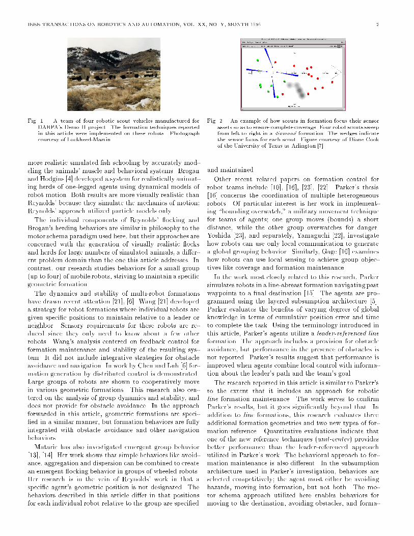
tems integrate several goal oriented behaviors simultane-ously, systems using this technique are able to navigateto waypoints, avoid hazards and keep formation at thesame time. The initial target for this work is a team ofrobotic vehicles intended to be �elded as a scout unit by theU.S. Army (Figure 1). Formation is important in this andother military applications where sensor assets are limited.Formations allow individual team members to concentratetheir sensors across a portion of the environment, whiletheir partners cover the rest. Air Force �ghter pilots forinstance, direct their visual and radar search responsibili-ties depending on their position in a formation [9]. Roboticscouts also bene�t by directing their sensors in di�erentareas to ensure full coverage (Figure 2 [7]). The approachis potentially applicable in many other domains such assearch and rescue, agricultural coverage tasks and securitypatrols.
The robots in this research are mechanically similar, orin the case of simulation, identical. Nevertheless, they areconsidered heterogeneous since each robot's position in for-mation depends on a unique identi�cation number (ID),i.e., heterogeneity arises from functional rather than phys-ical di�erences. This is important in applications whereone or more of the agents are dissimilar. In Army scout
This work was conducted at the Mobile Robot Laboratory, GeorgiaInstitute of Technology and was supported by ONR/DARPA Grant# N00014-94-1-0215.
T. Balch is with the Computer Science Department, CarnegieMellon University, Pittsburgh, PA 15213-3891 USA (e-mail:[email protected]).
R. Arkin is Director of the Mobile Robot Laboratory, College ofComputing, Georgia Institute of Technology, 801 Atlantic Drive, At-lanta, GA 30332-0280 (e-mail: [email protected]).
platoons for instance, the leader is not usually at the frontof the formation, but in the middle, or to one side.The formation behaviors were implemented as mo-
tor schemas, within the Autonomous Robot Architecture(AuRA) architecture, and as steering and speed behav-iors within the Unmanned Ground Vehicle (UGV) DemoII architecture. In both cases, the individual behaviors runas concurrent asynchronous processes with each behaviorrepresenting a high-level behavioral intention of the agent.Perceptions are directly translated into a response vector inAuRA, or as turning or speed votes on the UGV. Readersare referred to [2] and [18] for more information on schema-based reactive control and the DAMN Arbiter used withinthe UGV Demo II architecture.
A. Background
Formation behaviors in nature, like ocking and school-ing, bene�t the animals that use them in various ways.Each animal in a herd, for instance, bene�ts by minimiz-ing its encounters with predators [20]. By grouping, ani-mals also combine their sensors to maximize the chance ofdetecting predators or to more e�ciently forage for food.Studies of ocking and schooling show that these behav-iors emerge as a combination of a desire to stay in thegroup and yet simultaneously keep a separation distancefrom other members of the group [8]. Since groups of arti-�cial agents could similarly bene�t from formation tactics,robotics researchers and those in the arti�cial life commu-nity have drawn from these biological studies to developformation behaviors for both simulated agents and robots.Approaches to formation generation in robots may be dis-tinguished by their sensing requirements, their method ofbehavioral integration, and their commitment to preplan-ning. A brief review of a few of these e�orts follows.An early application of arti�cial formation behavior was
the behavioral simulation of ocks of birds and schoolsof �sh for computer graphics. Important results in thisarea originated in Craig Reynolds pioneering work [17]. Hedeveloped a simple egocentric behavioral model for ock-ing which is instantiated in each member of the simulatedgroup of birds (or \boids"). The behavior consists of sev-eral separate components, including: inter-agent collisionavoidance, velocity matching and ock centering. Each ofthe components is computed separately, then combined formovement. An important contribution of Reynold's workis the generation of successful overall group behavior whileindividual agents only sense their local environment andclose neighbors. Improvements to this approach have re-cently been made by Tu and Terzopoulos and separately byBrogan and Hodgins. Tu and Terzopoulos [19] developed
IEEE TRANSACTIONS ON ROBOTICS AND AUTOMATION, VOL. XX, NO. Y, MONTH 1999 2
Fig. 1. A team of four robotic scout vehicles manufactured forDARPA's Demo II project. The formation techniques reportedin this article were implemented on these robots. Photographcourtesy of Lockheed-Martin.
more realistic simulated �sh schooling by accurately mod-eling the animals' muscle and behavioral systems. Broganand Hodgins [4] developed a system for realistically animat-ing herds of one-legged agents using dynamical models ofrobot motion. Both results are more visually realistic thanReynolds' because they simulate the mechanics of motion;Reynolds' approach utilized particle models only.
The individual components of Reynolds' ocking andBrogan's herding behaviors are similar in philosophy to themotor schema paradigmused here, but their approaches areconcerned with the generation of visually realistic ocksand herds for large numbers of simulated animals, a di�er-ent problem domain than the one this article addresses. Incontrast, our research studies behaviors for a small group(up to four) of mobile robots, striving to maintain a speci�cgeometric formation.
The dynamics and stability of multi-robot formationshave drawn recent attention [21], [6]. Wang [21] developeda strategy for robot formations where individual robots aregiven speci�c positions to maintain relative to a leader orneighbor. Sensory requirements for these robots are re-duced since they only need to know about a few otherrobots. Wang's analysis centered on feedback control forformation maintenance and stability of the resulting sys-tem. It did not include integrative strategies for obstacleavoidance and navigation. In work by Chen and Luh [6] for-mation generation by distributed control is demonstrated.Large groups of robots are shown to cooperatively movein various geometric formations. This research also cen-tered on the analysis of group dynamics and stability, anddoes not provide for obstacle avoidance. In the approachforwarded in this article, geometric formations are speci-�ed in a similar manner, but formation behaviors are fullyintegrated with obstacle avoidance and other navigationbehaviors.
Mataric has also investigated emergent group behavior[13], [14]. Her work shows that simple behaviors like avoid-ance, aggregation and dispersion can be combined to createan emergent ocking behavior in groups of wheeled robots.Her research is in the vein of Reynolds' work in that aspeci�c agent's geometric position is not designated. Thebehaviors described in this article di�er in that positionsfor each individual robot relative to the group are speci�ed
Fig. 2. An example of how scouts in formation focus their sensorassets so as to ensure complete coverage. Four robot scouts sweepfrom left to right in a diamond formation. The wedges indicatethe sensor focus for each scout. Figure courtesy of Diane Cookof the University of Texas at Arlington [7].
and maintained.
Other recent related papers on formation control forrobot teams include [10], [16], [23], [22]. Parker's thesis[16] concerns the coordination of multiple heterogeneousrobots. Of particular interest is her work in implement-ing \bounding overwatch," a military movement techniquefor teams of agents; one group moves (bounds) a shortdistance, while the other group overwatches for danger.Yoshida [23], and separately, Yamaguchi [22], investigatehow robots can use only local communication to generatea global grouping behavior. Similarly, Gage [10] examineshow robots can use local sensing to achieve group objec-tives like coverage and formation maintenance.
In the work most closely related to this research, Parkersimulates robots in a line-abreast formation navigating pastwaypoints to a �nal destination [15]. The agents are pro-grammed using the layered subsumption architecture [5].Parker evaluates the bene�ts of varying degrees of globalknowledge in terms of cumulative position error and timeto complete the task. Using the terminology introduced inthis article, Parker's agents utilize a leader-referenced line
formation. The approach includes a provision for obstacleavoidance, but performance in the presence of obstacles isnot reported. Parker's results suggest that performance isimproved when agents combine local control with informa-tion about the leader's path and the team's goal.
The research reported in this article is similar to Parker'sto the extent that it includes an approach for roboticline formation maintenance. The work serves to con�rmParker's results, but it goes signi�cantly beyond that. Inaddition to line formations, this research evaluates threeadditional formation geometries and two new types of for-mation reference. Quantitative evaluations indicate thatone of the new reference techniques (unit-center) providesbetter performance than the leader-referenced approachutilized in Parker's work. The behavioral approach to for-mation maintenance is also di�erent. In the subsumptionarchitecture used in Parker's investigation, behaviors areselected competitively; the agent must either be avoidinghazards, moving into formation, but not both. The mo-tor schema approach utilized here enables behaviors formoving to the destination, avoiding obstacles, and forma-

IEEE TRANSACTIONS ON ROBOTICS AND AUTOMATION, VOL. XX, NO. Y, MONTH 1999 3
3 1 24
1
3
4
2
1
2
4
3
3 1
24
Fig. 3. Formations for four robots. From left to right: line, column, diamond, wedge. Each robot has a speci�c position to maintain in theformation, as indicated by its identi�cation number (ID).
tion keeping to be simultaneously active and cooperativelycombined. Additionally, as well as running in simulation,our approach is validated on two di�erent types of mobilerobot platform.
II. Approach
Several formations for a team of four robots are consid-ered (Figure 3):
� line - where the robots travel line-abreast.� column - where the robots travel one after the other.� diamond - where the robots travel in a diamond.� wedge - where the robots travel in a \V".
These formations are used by U.S. Army mechanizedscout platoons on the battle�eld [3]. For each formation,each robot has a speci�c position based on its identi�cationnumber (ID). Figure 3 shows the formations and robots'positions within them. Active behaviors for each of thefour robots are identical, except in the case of Robot 1 inleader-referenced formations (see below). The task for eachrobot is to simultaneously move to a goal location, avoidobstacles, avoid colliding with other robots and maintain aformation position, typically in the context of a higher-levelmission scenario.
Formation maintenance is accomplished in two steps:�rst, a perceptual process, detect-formation-position,determines the robot's proper position in formation basedon current environmental data; second, the motor processmaintain-formation, generates motor commands to di-rect the robot toward the correct location. In the case ofAuRA's motor schema control, the command is a move-ment vector towards the desired location. For the UGVDemo II Architecture, separate votes are cast for steeringand speed corrections towards the formation position. Mo-tor commands for each architecture are covered in moredetail below.
Each robot computes its proper position in the forma-tion based on the locations of the other robots. Threetechniques for formation position determination have beenidenti�ed:
� Unit-center-referenced: a unit-center is computedindependently by each robot by averaging the x and ypositions of all the robots involved in the formation.Each robot determines its own formation position rel-ative to that center.
� Leader-referenced: each robot determines its for-mation position in relation to the lead robot (Robot1). The leader does not attempt to maintain forma-tion; the other robots are responsible for formationmaintenance.
� Neighbor-referenced: each robot maintains a posi-tion relative to one other predetermined robot.
The orientation of the formation is de�ned by a line fromthe unit center to the next navigational waypoint. To-gether, the unit-center and the formation orientation de�nea local coordinate system in which the formation positionsare described. This local coordinate system is re-computedat each movement step. The formation relationships aredepicted in Figure 4. Arrows show how the formation po-sitions are determined. Each arrow points from a robot tothe associated reference. The perceptual schema detect-formation-position uses one of these references to deter-mine the position for the robot. Spacing between robotsis determined by the desired spacing parameter of detect-formation-position.
Each robot determines the positions of its peers by directperception of the other robots, by transmission of world co-ordinates obtained from global positioning systems (GPS)or by dead reckoning. When inter-robot communicationis required, the robots transmit their current position inworld coordinates with updates as rapidly as required forthe given formation speed and environmental conditions.Position errors and latency in the transmission of positionalinformation can negatively impact performance. In simu-lation runs there was no position error or communicationlatency. In experimental laboratory runs Nomad 150s ex-perienced less than 10 centimeters position error; commu-nication latency was approximately one second. Positionerror for the current UGV implementation was less thanone meter due to the use of DGPS; communication laten-cies were sometimes as great as seven seconds.
The remainder of this article describes the implementa-tion of these formation behaviors in simulation and on twotypes of mobile robot. The next section covers a motorschema implementation. It includes a performance analy-sis of the motor schema-based system in turns and acrossobstacle �elds. The behaviors are demonstrated on No-madic Technologies Nomad 150 robots. Comparisons be-tween mobile robot and simulation runs support the signif-icance of the data gathered in simulation experiments.

IEEE TRANSACTIONS ON ROBOTICS AND AUTOMATION, VOL. XX, NO. Y, MONTH 1999 4
1
4
3
2
1
4 2
3 1
4 2
3
Fig. 4. Formation position determined by various referencing techniques (from left to right: unit-center, leader, neighbor)
Section 4 covers the implementation of this approach onthe UGV Demo II Architecture. The UGV platform re-quires a decoupling of motor control into separate steeringand speed behaviors. In spite of this di�erence, the UGVimplementationutilizes the same perceptual mechanisms asthe motor schema approach for determining a robot's po-sition in formation. Both implementations \push" a robotback into position with a variable strength depending onhow far it is out of position. Implementation of the sameapproach on these two very di�erent platforms illustratesits portability and e�ectiveness.
III. Motor Schema-based Formation Control
Several motor schemas, move-to-goal, avoid-static-obstacle, avoid-robot and maintain-formation imple-ment the overall behavior for a robot to move to a goal loca-tion while avoiding obstacles, collisions with other robotsand remaining in formation. An additional backgroundschema, noise, serves as a form of reactive \grease", deal-ing with some of the problems endemic to purely reactivenavigational methods such as local maxima, minima andcyclic behavior [1]. Each schema generates a vector rep-resenting the desired behavioral response (direction andmagnitude of movement) given the current sensory stimuliprovided by the environment. A gain value is used to in-dicate the relative importance of the individual behaviors.The high-level combined behavior is generated by multi-plying the outputs of each primitive behavior by its gain,then summing and normalizing the results. The gains andother schema parameters used for the experimental simu-lations reported in this article are listed in Table I. TheAppendix contains information on the speci�c computationof the individual schemas used in this research. See [1] fora complete discussion of the computational basis of motorschema-based navigation.
Once the desired formation position is known, themaintain-formation motor schema generates a move-ment vector towards it. The vector is always in the di-rection of the desired formation position, but the magni-tude depends on how far the robot is away from it. Figure5 illustrates three zones, de�ned by distance from the de-sired position, used for magnitude computation. The radiiof these zones are parameters of the maintain-formation
schema. In the �gure, Robot 3 attempts to maintain a po-sition to the left of and abeam Robot 1. Robot 3 is in the
Parameter Value Units
avoid-static-obstaclegain 1.5sphere of in uence 50 metersminimum range 5 meters
avoid-robotgain 2.0sphere of in uence 20 metersminimum range 5 meters
move-to-goalgain 0.8
noisegain 0.1persistence 6 time steps
maintain-formationgain 1.0desired spacing 50 meterscontrolled zone radius 25 metersdead zone radius 0 meters
TABLE I
Motor schema parameters for formation navigation
experiments in simulation.
1
3
Ballistic Zone
Controlled Zone
Dead Zone
Fig. 5. Zones for the computation of maintain-formation magni-tude
controlled zone, so a moderate force towards the desiredposition (forward and right) is generated by maintain-
formation. In general, the magnitude of the vector iscomputed as follows:
� Ballistic zone: the magnitude is set at its maximum,which equates to the schema's gain value.
� Controlled zone: the magnitude varies linearly froma maximum at the farthest edge of the zone to zero atthe inner edge.
� Dead zone: in the dead zone vector magnitude isalways zero.
The role of the dead zone is to minimize the problems as-sociated with position reporting errors and untimely com-
IEEE TRANSACTIONS ON ROBOTICS AND AUTOMATION, VOL. XX, NO. Y, MONTH 1999 5
munication. The dead zone provides a stable target area(as opposed to a point) that provides high tolerance to po-sitional uncertainty. It is assumed that the dead zone isgreater than or equal to the errors associated with theseuncertainties.
In simulation, no dead zone was required for stable per-formance (dead zone radius is set to 0), but mobile robotsrequire a small dead zone to avoid oscillations about theformation position due to latency in communication or er-rors in position determination. These factors are negligiblein the simulation studies.
Recall that the orientation of the formation is de�ned bya line from the unit center to the next navigational way-point. Together, the unit-center and the formation orien-tation de�ne a local coordinate system in which the forma-tion positions are described. This local coordinate systemis re-computed at each movement step. The motion of theformation as a whole also arises from the impetus providedby the other active behaviors, primarilymove-to-goal.
The formation behavior is only one component of therobots' overt actions. In extreme conditions, for example,if a barrier signi�cantly larger than the entire formation isencountered, then the formation will either move as a unitaround the barrier or will divide into subgroups with someproceeding around each side. The resultant action dependsupon the relative strength of the formation behavior tothe other goal-oriented behaviors (e.g.,move-to-goal). Ifthe goal attraction is very much stronger, the individualrobot's needs will take precedence. On the other hand if theformation behavior has a high gain and is thus a dominantfactor, the formation will act more or less like a single unitand not be allowed to divide. The level of \obedience" toremain in formation is controllable through the setting ofthe relative gain values of these behaviors during missionspeci�cation. This same discussion applies to when thereare multiple corridors in front of the robots or other similarconditions.
A. Motor Schema Results in Simulation
Results were generated using Georgia Tech's MissionLab
robot simulation environment [12]. MissionLab1 runs onUnix machines (SunOS and Linux) using the X11 graph-ical windowing system. The simulation environment is a1000 by 1000 meter two dimensional �eld upon which vari-ous sizes and distributions of circular obstacles can be scat-tered. Each simulated robot is a separately running C pro-gram that interacts with the simulation environment viaa Unix socket. The simulation displays the environmentgraphically and maintains world state information which ittransmits to the robots as they request it. Figure 6 showsfour typical simulation runs. The robots are displayed as�ve-sided polygons, while the obstacles are black circles.The robots' paths are depicted with solid lines.
Sensors allow a robot to distinguish between three per-ceptual classes: robots, obstacles and goals. When one of
1MissionLab software is available on the World Wide Web athttp://www.cc.gatech.edu/aimosaic/robot-lab/research
the robot's perceptual processes requires obstacle informa-tion a request for that data is sent via a socket to the simu-lation process. A list comprised of angle and range data foreach obstacle in sensor range is returned. Robot and goalsensor information is similarly provided. A robot moves bytransmitting its desired velocity to the simulation processwhich automatically maintains the position and heading ofeach robot.
The line, column, wedge and diamond formations wereimplemented using both the unit-center-referenced andleader-referenced approaches. Figure 6 illustrates robotsmoving in each of the basic formations with the leader-referenced approach. In each of these simulation runs therobots were �rst initialized on the left side of the simu-lation environment, then directed to proceed to the lowercenter of the frame. After the formation was established,a 90o turn to the left was initiated. Results were similarlyobtained for the unit-center-referenced formations.
Qualitative di�erences between the two approaches canbe seen as the formation of robots moves around obstaclesand through turns (Figure 7). For leader-referenced for-mations any turn by the leader causes the entire formationto shift accordingly, but when a \follower" robot turns,the others in formation are not a�ected. In unit-center-referenced formations any robot move or turn impacts theentire formation. In turns for leader-referenced formations,the leader simply heads in the new direction; the otherrobots must adjust to move into position. In unit-center-referenced turns, the entire formation initially appears tospin about a central point, as the robots align with a newheading.
To investigate quantitative di�erences in performancebetween the various formation types and references, twoexperiments were conducted in simulation: the �rst eval-uates performance in turns, and the second evaluates per-formance across an obstacle �eld.
B. Motor Schema Performance in Turns
To evaluate performance in turns, the robots are com-manded to travel 250 meters, turn right, then travel an-other 250 meters. The robots attempt to maintain forma-tion throughout the test. A turn of 90 degrees was se-lected for this initial study, but performance likely variesfor di�erent angles. In this evaluation, no obstacles arepresent. For statistical signi�cance, 10 simulations wererun for each formation type and reference. To ensure therobots are in correct formation at the start of the evalua-tion, they travel 100 meters to align themselves before theevaluation starts. This initial 100 meters is not included inthe 500 meter course evaluation. A run is complete whenthe unit-center of the formation is within 10 meters of thegoal location. Even though a unit-center computation isused to determine task completion, it is not required forleader-referenced formation maintenance.
Three performance metrics are employed: path lengthratio, average position error, and percent of time out of for-mation. Path length ratio is the average distance traveledby the four robots divided by the straight-line distance of

IEEE TRANSACTIONS ON ROBOTICS AND AUTOMATION, VOL. XX, NO. Y, MONTH 1999 6
Fig. 6. Four robots in leader-referenced diamond, wedge, line and column formations.
Fig. 7. Comparison of leader-referenced (left) and unit-center-referenced (right) diamond formations.
the course. A lower value for this ratio indicates better per-formance. A ratio of 1.02, for example, means the robotshad to travel an average of 2% further because they were information. Position error is the average displacement fromthe correct formation position throughout the run. Robotsoccasionally fall out of position due to turns, etc.; this is re- ected in the percent of time out of formation data. To be\in position" a robot must be within 5 meters of its correctposition. 5 meters was selected arbitrarily, but amountsto 10% of the overall formation spacing. Results for theturn experiments are summarized in Table 2; the standarddeviation for each quantity is listed in parentheses.
For turns in a unit-center-referenced formation, diamondformations perform best. The diamond formation mini-mizes path ratio (1.03), position error (6.8 meters) and timeout of formation (20.1 %). Unit-center-referenced forma-tions appear to turn by rotating about their unit-center, sorobots on the outside edge of the formation have to travelfurther in turns. The improved performance in diamond
formations may re ect the smaller \moment of inertia" ascompared to other formations. In the diamond formation,no robot is further than 50 meters from the unit-center.In contrast, the anking robots in wedge, line, and column
formations are 75 meters from the unit center.
For turns in a leader-referenced formation, wedge andline formations perform about equally. The line for-mation minimizes position error (8.2 meters), while thewedge formation minimizes time out of formation (17.3%). Leader-referenced formations pivot about the leaderin sharp turns. Robots signi�cantly behind the leader willbe pushed through a large arc during the turn. line andwedge formations work well because fore and aft di�erencesbetween the lead robot and other robots (0 and 50 metersrespectively) are less than diamond and column formations
(100 and 150 meters). Performance for column formationsis signi�cantly worse than that for line, wedge and diamondformations because the trail robot is 150 meters back.
C. Motor Schema Performance in an Obstacle Field
Performance was also measured for four robots navigat-ing across a �eld of obstacles in formation. In this eval-uation, the robots are commanded to travel between twopoints 500 meters apart. Obstacles are placed randomly sothat 2% of the total area is covered with obstacles 10 to15 meters in diameter. As in the turn evaluation above,path length ratio, average position error, and percent outof formation is reported for each run. Data from runs on10 random scenarios were averaged for each datapoint, thestandard deviation of each factor is also recorded. Resultsfor this experiment are summarized in Table 3.
For travel across an obstacle �eld, the best performanceis found using column formations. column formations min-imize position error and percent time out of formation forunit-center- and leader-referenced formations. This resultre ects the fact that column formations present the small-est cross-section as they traverse the �eld. Once the leadrobot shifts laterally to avoid an obstacle, the others canfollow in its \footsteps."
In most instances, unit-center-referenced formations farebetter than leader-referenced formations. A possible ex-planation is an apparent emergent property of unit-center-referenced formations; the robots appear to work togetherto minimize formation error. For instance, if one robot getsstuck behind an obstacle the others \wait" for it. The unit-center is anchored by the stuck robot so the maintain-
formation schema instantiated in the other robots holdsthem back until the stuck robot navigates around the ob-stacle. This does not occur in leader-referenced formations.

IEEE TRANSACTIONS ON ROBOTICS AND AUTOMATION, VOL. XX, NO. Y, MONTH 1999 7
Path Ratio Position Error Time out of FormationFormation Type Unit Leader Unit Leader Unit Leader
diamond 1.03 (0.08) 1.06 (0.08) 6.8 (0.2) m 11.4 (5.9) m 20.8 (0.3) % 21.6 (10.8) %wedge 1.04 (0.09) 1.06 (0.09) 9.4 (4.5) m 9.1 (6.2) m 25.6 (6.0) % 17.3 (9.6) %column 1.04 (0.06) 1.16 (0.02) 8.4 (5.6) m 21.1 (17.3) m 22.4 (8.1) % 32.4 (22.8) %line 1.04 (0.10) 1.05 (0.06) 8.5 (5.5) m 8.2 (5.1) m 25.7 (7.4) % 18.9 (10.8) %
TABLE II
Performance for a 90 degree turn for both unit-center and leader-referenced formations, smaller numbers are better.
The standard deviation is indicated within parentheses.
Path Ratio Position Error Time out of FormationFormation Type Unit Leader Unit Leader Unit Leader
diamond 1.05 (0.04) 1.08 (0.05) 5.2 (1.9) m 7.1 (5.0) m 38.9 (15.0) % 34.8 (21.8) %wedge 1.04 (0.04) 1.08 (0.05) 5.2 (1.4) m 9.5 (8.4) m 37.9 (9.4) % 37.2 (24.3) %column 1.05 (0.04) 1.08 (0.04) 3.4 (1.6) m 6.4 (5.2) m 23.2 (11.8) % 28.5 (20.2) %Line 1.05 (0.05) 1.05 (0.04) 5.3 (1.5) m 9.4 (8.5) m 36.1 (10.5) % 35.6 (23.8) %
TABLE III
Performance for navigation across an obstacle field.
Overall path length for robots in a leader-referenced for-mation is generally longer than in unit-center-referencedformations. This may be because any turn or detour bythe lead robot is followed by all four robots, even if theirpath is not obstructed by the obstacle the leader is avoid-ing. A detour by the lead robot in a unit-center-referencedformation a�ects the entire formation, but the impact is75% less than that found in leader-referenced formationssince in the unit-center case an individual robot must shift4 meters to move the formation's unit-center 1 meter.
D. Motor Schema Results on Mobile Robots
Fig. 8. Shannon and Sally, the two Nomad 150 robots used in for-mation experiments.
Experiments were conducted in the Mobile Robot Lab-oratory to demonstrate formation performance on mobilerobots and to validate the quantitative results from simu-lation experiments. MissionLab is designed so that at run-time a researcher may choose between a simulated run, or arun on physical robots. The same behavioral control codeis used both in simulation and to control the robots. Cur-rently, the system can command Denning MRV-3, MRV-2and DRV robots, as well as Nomadic Technologies Nomad150 robots and a Hummer 4-wheel drive vehicle instru-mented for robotic use at Georgia Tech.
The experimental platform for the results reported hereis a two-robot team of Nomad 150 robots: Shannon and
Sally (Figure 8). Nomad 150s are three-wheeled holonomicrobots equipped with a separately steerable turret and 16ultrasonic range sensors for hazard detection. The Nomad150s are controlled using on-board laptop computers run-ning Linux. They communicate over a wireless networksupporting Unix sockets via TCP/IP.Experimental runs were conducted in a test area mea-
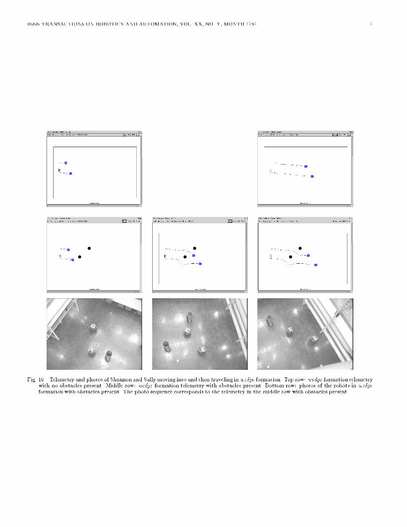
suring approximately 10 by 5 meters. The robots weredirected to navigate from West to East across the room(left to right in Figures 9 through 11). Runs were con-ducted for line, wedge, and column unit-center referencedformations. Separate runs were conducted for each type offormation with and without obstacles. The robots estimatetheir position using shaft encoders. In order to communi-cate the formation's unit-center each robot communicatesits position to the other over a wireless network.
Parameter Value Units
avoid-static-obstaclegain 1.5sphere of in uence 2.0 metersminimum range 0.5 meters
avoid-robotgain 1.0sphere of in uence 1.2 metersminimum range 0.6 meters
move-to-goalgain 1.0
maintain-formationgain 2.0desired spacing 1.5 meterscontrolled zone radius 0.75 metersdead zone radius 0.1 meters
TABLE IV
Motor schema parameters for formation navigation on
Nomad 150 robots.
The behavioral con�guration of the robots was the sameas that used in simulation runs, except that parameter val-ues were adjusted to account for the use of smaller robots(Nomad 150s versus HMMWVs) and a smaller test area.

IEEE TRANSACTIONS ON ROBOTICS AND AUTOMATION, VOL. XX, NO. Y, MONTH 1999 8
Fig. 9. Telemetry and photos of Shannon and Sally moving into and then traveling in column formation. Top row: column formationtelemetry with no obstacles present. Middle row: column formation telemetry with obstacles present. Bottom row: photos of the robotsin column formationwith obstacles present. The photo sequence corresponds to telemetry in the middle row with obstacles (wastebaskets)present. This experiment was recorded in the foyer of the Georgia Tech Manufacturing Research Center, looking down on the robotsfrom twenty feet above so that formation positions are more easily observed
IEEE TRANSACTIONS ON ROBOTICS AND AUTOMATION, VOL. XX, NO. Y, MONTH 1999 9
Fig. 10. Telemetry and photos of Shannon and Sally moving into and then traveling in wedge formation. Top row: wedge formation telemetrywith no obstacles present. Middle row: wedge formation telemetry with obstacles present. Bottom row: photos of the robots in wedge
formation with obstacles present. The photo sequence corresponds to the telemetry in the middle row with obstacles present.

IEEE TRANSACTIONS ON ROBOTICS AND AUTOMATION, VOL. XX, NO. Y, MONTH 1999 10
Fig. 11. Telemetry and photos of Shannon and Sally moving into and then traveling in line formation. Top row: line formation telemetrywith no obstacles present. Middle row: line formation telemetry with obstacles present. Bottom row: photos of the robots in line
formation with obstacles present. The photo sequence corresponds to the telemetry in the middle row with obstacles present.
Fig. 12. A comparison of telemetry from actual robot formation runs (top row) and runs in in simulation (bottom row). From left to right:line, wedge and column formations.

IEEE TRANSACTIONS ON ROBOTICS AND AUTOMATION, VOL. XX, NO. Y, MONTH 1999 11
Table IV lists the motor schema parameter values usedon the mobile robots. The noisemotor schema was not ac-tivated in these experiments because sensor noise providesa su�cient random input to help robots around shallowlocal minima.
Figures 9 through 11 show Shannon and Sally travers-ing the test area in column, wedge, and line formationswith and without obstacles present. For comparison, theruns with and without obstacles for each formation typeare reproduced on the top and middle of each page, whilesnapshots of the robots during the run with obstacles areshown at the bottom.During the runs, the robots remained in their appropri-
ate formation position, except for short periods while ne-gotiating obstacles. In the case of obstacles, it was evidentthat one robot would \wait" for the other robot if it gotdelayed behind an obstacle.
To further validate the accuracy of the simulation data,an additional set of simulation runs matching the exper-imental setup were conducted. The simulations used thesame parameter values and obstacle locations as in the mo-bile robot tests. Results for these tests are shown in Figure12. Di�erences between the simulation and real runs areprimarily due to sensor noise and positional inaccuracies.
IV. Formation Control for the UGV Demo II
Architecture
UGV Demo II is an ARPA-funded project aimed at �eld-ing a robotic scout platoon for the Army. Each UnmannedGround Vehicle (UGV) is a High Mobility MultipurposeWheeled Vehicle (HMMWV) equipped with position, vi-sion and hazard sensors, control computers and actuationdevices for steering and speed control. Four UGVs werebuilt by Lockheed Martin, and up to three have been oper-ated simultaneously in formation (Figure 1). This sectionshows how formation behaviors were adapted for use onthese autonomous robots.
The UGV Demo II Architecture di�ers from the motorschema method where behaviors generate both a directionand magnitude. Instead, in the UGV Demo II Architec-ture, separate motor behaviors are developed for the speedand turning components of a behavior. The behaviors arecoordinated by speed and turn arbiters. Each arbiter runsconcurrently and accepts votes from the various active mo-tor behaviors. For turning, behaviors vote for one of 30discrete egocentric steering angles; the angle with the mostvotes wins. A behavior may actually cast several votesfor separate headings at once, where the votes are spreadabout a central angle with a Gaussian distribution. Inspeed voting, the lowest speed vote always wins. Details onthe mathematical formation of the arbitration process areavailable in [11]. One strength of the formation behaviorslies in their ability to be easily reformulated for this andother alternate behavior-based coordination methods.
As in the case of motor schema-based robots, the UGVsmust simultaneously navigate to a goal position, avoid colli-sions with hazards and remain in formation. This is accom-plished by concurrent activation of independent behaviors
for each. Here we will deal only with the formation behav-iors.
For the UGV, formations and formation positions weredetermined in the same way as described in Section II. Theapproach described here for maintaining a given formationposition is equally applicable to unit-center, leader, andneighbor referenced formations, but only unit-center wasimplemented. We now focus on the control strategies formoving a robot into formation, given the desired positionis known.
Car-like non-holonomic constraints on UGV movementcall for a revision of the formation motor behavior. In thenon-holonomic case the robot's heading during formationcorrections signi�cantly impacts its ability to remain in po-sition. Not only should the vehicle be in the right location,but its heading should be aligned with the axis of the for-mation. If it is very far o� heading, the robot will quicklyfall out of position either laterally, fore-aft or both. A tech-nique used by pilots for aircraft formation [9] is well suitedfor this task: positioning is decomposed into fore-aft andside-side corrections. Fore-aft corrections are made by ad-justing speed only, while lateral corrections are made byadjusting heading only. Each correction is applied inde-pendently. A consequence of the approach is that when arobot is ahead of its position it will not attempt to turnaround, but just slow down. The following observationssummarize the approach:
For speed selection:
� If the robot is in formation, the best speed for main-taining that formation is the current speed.
� If the vehicle is behind its position, it should speed up.� If the vehicle is in front of its position, it should slowdown.
� The selected change in speed should depend on howfar out of position the robot is.
� Since the speed arbiter implemented in the Demo IIArchitecture selects the lowest speed vote of all theactive behaviors for output to the vehicle, formationspeed control is only possible by slowing down.
For steering:
� If the robot is in formation, the best heading for posi-tion maintenance is the formation axis.
� If the robot is out of position laterally and the forma-tion is moving, it should turn towards the formationaxis with an angle that depends on how far out ofposition it is.
� If the robot is out of position and the formation hasstopped moving, the robot should head directly to-wards its position.
A. UGV Behaviors for Formation
While the motor schema approach combines the lateraland fore-aft components of position correction into one be-havior, the Demo II Architecture requires a decompositionof control into separate steering and speed control compo-nents. Two behaviors, maintain-formation-speed andmaintain-formation-steer run concurrently to keep the

IEEE TRANSACTIONS ON ROBOTICS AND AUTOMATION, VOL. XX, NO. Y, MONTH 1999 12
Robot
Formation AxisF
Formation Position
pos Fdir
R Rpos dir
Fig. 13. Illustration of terms used in describing formation behaviorsfor UGVs. In this diagram the robot is behind and to the rightof the desired position in formation. The robot's position anddirection are indicated by Rpos and Rdir. The desired formationposition is Fpos. The formation is moving in the direction Fdir .
vehicle in position. The outputs of these two behaviorsroughly correspond to the orthogonal components of thesingle-vector output motor schema. Each UGV behaviordetermines an appropriate value at each movement stepand votes accordingly. The votes, along with those fromother behaviors are tallied and acted upon by the speedand steering arbiters.To facilitate the discussion that follows, the following
formation terms are introduced (see Figure 13):� Rpos; Rdir the robot's present position and heading.� Rmag , the robot's present speed.� Fpos, the robot's proper position in formation.� Fdir, the direction of the formation's movement; to-wards the next navigational waypoint.
� Faxis, the formation's axis, a ray passing through Fposin the Fdir direction.
� Hdesired, desired heading, a computed heading thatwill move the robot into formation.
� �heading , the computed heading correction.� �speed, the computed speed correction.� Vsteer, steer vote, representing the directional outputof the motor behavior, sent to the steering arbiter.
� Vspeed, speed vote, the speed output of the motor be-havior, sent to the speed arbiter.
The maintain-formation-speed behavior �rst deter-mines the magnitude of the required speed correction, thencasts its vote by adding the correction to the current speed:
Vspeed = Rmag +K � �speed
K is a parameter set before runtime to adjust the rateof correction. �speed is the correction computed by theformation speed behavior. It varies from �1:0 (slow down)to 1:0 (speed up) depending on how far fore or aft the robotis of the desired position. Three zones, perpendicular to theformation axis and de�ned by distance fore or aft of Fposdetermine �speed (Figure 14). The size of these zones are
parameters of the formation behavior. �speed is set negativeif the robot is in front of Fpos and positive otherwise. Ina manner similar to the motor schema-based approach themagnitude is computed as follows:� Ballistic zone : 1.0� Controlled zone : the magnitude varies linearly froma maximum of 1.0 at the farthest edge of the zone tozero at the inner edge.
� Dead zone : in the dead zone the magnitude is alwayszero.
Themaintain-formation-steer behavior follows a sim-ilar sequence of steps to determine an egocentric steeringdirection, (the angle for the front wheels with respect tothe vehicle body. The behavior computes the magnitudeof correction necessary, the desired heading for that correc-tion, then �nally, it votes for an appropriate steering angle.The magnitude of correction is determined based on howfar laterally the robot is from its formation position. Themaximum correction is for the robot to head directly to-
wards the formation axis, the minimum is for the robotto head directly along the formation axis. The magnitudeof �heading computed by the formation heading behavior isdetermined as follows (Figure 14):� Ballistic zone: 90o, i.e. head directly towards theaxis.
� Controlled zone: the turn varies linearly from amaximum of 90o at the farthest edge of the zone to0o at the inner edge.
� Dead zone: 0o, i.e. head parallel to the axis.The sign of the correction is set according whether the
robot is left or right of the formation axis. If the robot isleft of the axis, calling for a right turn, the sign is positive, itis set negative otherwise. Hdesired can now be determinedwith reference to the formation axis:
Hdesired = Fdir � �heading
As the robot moves forward, this heading will simultane-ously bring it to and properly align it with the formationaxis. In the special case where the formation has stoppedmoving, Hdesired is instead set to take the robot directlyto its position:
Hdesired = Fpos � Rpos
Finally, Hdesired is translated into an egocentric angle forthe vehicle's front wheels:
Vsteer = Hdesired � Rdir
Positive angles indicate a right turn and negative ones a leftturn. If the result is either greater than 180o or less than�180o, 360o is added or subtracted to ensure the result iswithin bounds. Finally the angle is clipped to the physicallimits of the vehicle.
V. Results for UGV Demo II Mobile Robots
The behaviors were initially implemented and evaluatedat Georgia Tech using a single-robot simulator provided by

IEEE TRANSACTIONS ON ROBOTICS AND AUTOMATION, VOL. XX, NO. Y, MONTH 1999 13
Con
trol
led
Zon
e
Bal
list
ic Z
one
Con
trol
led
Zon
e
Dea
d Z
one
Bal
list
ic Z
one
R
Formation AxisF F
R
Dead Zone
Controlled Zone
Controlled Zone
Ballistic Zone
Ballistic Zone
Fig. 14. Zones centered on Fpos, the desired formation position. The zones on the left are used for computing speed, corrections, while thoseon the right are for heading corrections.
Fig. 15. Simulation of two DARPA UGVs in formation. The robotsare moving from left to right in a line formation. The robot atthe top of the �gure follows a �xed path, while the other robotutilizes behaviors described in the text to maintain a unit-center-referenced line formation.
Lockheed Martin. The behaviors were debugged by gen-erating an arti�cial �xed trajectory for one vehicle, thenobserving a simulated robot's attempt to maintain positionwith the �xed trajectory. Final integration with HMMWVswas completed by Lockheed Martin in Denver, Colorado.Positional information on the HMMWVs was reported viaDi�erential Global Positioning System (DGPS) receivers.
Figure 15 shows a sample run using this simulation. Thenotional robot follows a straight-line track from west toeast (left to right), while the simulated robot attempts tomaintain a line-abreast formation on the south. Initiallythe robot is pointed north, so it must turn to the southto get into position. Note that for the robot to get intoposition it must initially move away from the formationaxis, until it is turned around.
The unit-center referenced approach was used on theHMMWVs because the UGV Demo II Architecture onlyprovides the ability for a robot to slow down to keep for-mation. It was felt that since the leader would never slowdown to keep formation and a trailer could never speed upif it fell behind due to architectural limitations, a leader-referenced approach would be unsuccessful.
Formation played a key role in the success of UGV Demo
C in the Summer of 1995. At a technology demonstrationtwo HMMWVs ran through a series of tests including a se-quence of formations (Figures 17 and 16). The HMMWVsfollowed a one-kilometer course across open undulating ter-rain while smoothly shifting from column to wedge to line
then back to column formation.
Fig. 16. Reconstruction of the ground track of DARPA UGVs de-picted in Figure 17. The pair of robots are shown at three pointsin time as theymove from right to left. They transition from col-
umn (right) to wedge (center) to line formations as they traversethe �eld.
A formation expert software tool was developed and inte-grated into the UGV Demo II architecture which providesthe operator a graphical user-interface for the selection offormation types and parameters. This rule-based systemdrew both on the recommendations of military personneland doctrine as presented in U.S. Army manuals [3]. Theoperator uses this tool to determine what formations �t thetask confronting him.
Performance in these tests was limited by a communi-cations system that induced up to 7 seconds of latency inrobot to robot position reports. This problem points tothe utility of using a passive approach for locating teammembers, versus the explicit exchange of location based onDGPS readings.

IEEE TRANSACTIONS ON ROBOTICS AND AUTOMATION, VOL. XX, NO. Y, MONTH 1999 14
Fig. 17. Two DARPA UGVs in formation (from left to right: line, wedge, column)
VI. Summary and Conclusions
Reactive behaviors for four formations and three for-mation reference types were presented. The behaviorswere demonstrated successfully in the laboratory on mo-bile robots, and outdoors on non-holonomic 4-wheel-driveHMMWVs. In the course of these evaluations, the ap-proach was implemented on two reactive robotic architec-tures, AuRA and the UGV Demo II Architecture. TheAuRA implementation is conceptually simpler and appli-cable to holonomic robots, while the UGV implementationaddresses the additional complexity of non-holonomic ve-hicle control.
Separate experiments in simulation evaluated the utilityof the various formation types and references in turns andacross obstacle �elds. For 90o turns, the diamond forma-tion performs best when the unit-center-reference for for-mation position is used, while wedge and line formationswork best when the leader-reference is used. For travelacross an obstacle �eld, the column formation works bestfor both unit-center- and leader-referenced formations. Inmost cases, unit-center-referenced formations perform bet-ter than leader-referenced formations. Even so, some appli-cations probably rule out the use of unit-center-referencedformations:
� Human leader: A human serving as team leader can-not be reasonably expected to compute a formation'sunit-center on the y, especially while simultaneouslyavoiding obstacles. A leader-referenced formation ismost appropriate for this application.
� Communications restricted applications: Theunit-center approach requires a transmitter and re-ceiver for each robot and a protocol for exchanging po-sition information. Conversely, the leader-referencedapproach only requires one transmitter for the leader,and one receiver for each following robot. Bandwidthrequirements are cut by 75% in a four robot formation.
� Passive sensors for formation maintenance:
Unit-center-referenced formations place a great de-mand on passive sensor systems (e.g. vision). In a fourrobot visual formation for instance, each robot wouldhave to track three other robots which may spreadacross a 180o �eld of view. Leader- and neighbor-referenced formations only call for tracking one otherrobot.
VII. Acknowledgments
Doug MacKenzie and Jonathan Cameron wrote the sim-ulation software and helped debug the motor schema-basedformation behaviors. Doug MacKenzie also developed theCNL language and compiler in which the formation be-haviors are implemented in AuRA. Khaled Ali assisted inporting the implementation to the UGV Demo II Architec-ture. The authors are indebted to Betty Glass and MattMorgenthaler of Lockheed Martin for completing the in-tegration of the behaviors on DARPA's UGVs. We alsothank John Pani and Khaled Ali for their help in gather-ing the experimental data on Nomad 150 robots.
Appendix
I. Motor Schema Formulae
This appendix contains the methods by which each of theindividual primitive schemas used in this research computetheir component vectors. The results of all active schemasare summed and normalized prior to transmission to therobot for execution.
� Move-to-goal: Attract to goal with variable gain. Sethigh when heading for a goal.
Vmagnitude = adjustable gain valueVdirection = in direction towards perceived
goal
� Avoid-static-obstacle: Repel from object with vari-able gain and sphere of in uence. Used for collisionavoidance.Omagnitude =
0 for d > SS�dS�R
�Gfor R < d � S
1 for d � R
where:S = Adjustable Sphere of In uence
(radial extent of force fromthe center of the obstacle)
R = Radius of obstacleG = Adjustable Gaind = Distance of robot to center of obstacle
Odirection = along a line from robot to centerof obstacle moving away from obstacle
� Avoid-robot: is a special case of avoid-static-
obstacle where the robot to be avoided is treated as

IEEE TRANSACTIONS ON ROBOTICS AND AUTOMATION, VOL. XX, NO. Y, MONTH 1999 15
an obstacle using the formula above, but has a di�er-ent parameter set (See table IV).
� Noise: Random wander with variable gain and per-sistence. Used to overcome local maxima, minima,cycles, and for exploration.
Nmagnitude = Adjustable gain valueNdirection = Random direction that persists
for Npersistence steps(Npersistence is adjustable)
References
[1] R.C. Arkin. Motor schema based mobile robot navigation. In-ternational Journal of Robotics Research, 8(4):92{112, 1989.
[2] R.C. Arkin and T.R. Balch. Aura: principles and practice inreview. Journal of Experimental and Theoretical Arti�cial In-telligence, 9(2), 1997.
[3] Army. Field Manual No 7-7J. Department of the Army, Wash-ington, D.C., 1986.
[4] D.C. Brogan and J.K. Hodgins. Group behaviors for systemswith signi�cant dynamics. Autonomous Robots, 4(1):137{53,March 1997.
[5] R. Brooks. A robust layered control system for a mobile robot.IEEE Jour. of Robotics and Auto., RA-2(1):14, 1986.
[6] Q. Chen and J. Y. S. Luh. Coordination and control of a groupof small mobile robots. In Proceedings of the 1994 IEEE Inter-
national Conference on Robotics and Automation, pages 2315{2320, San Diego, CA, USA, 1994.
[7] D. J. Cook, P. Gmytrasiewicz, and L.B. Holder. Decision-theoretic cooperative sensor planning. IEEE Transactions on
Pattern Analysis and Machine Intelligence, 18(10):1013{23,1996.
[8] J.M. Cullen, E. Shaw, and H.A. Baldwin. Methods for measuringthe three-dimensionalstructure of �sh schools. Animal Behavior,13:534{543, 1965.
[9] U.S. Air Force. Air Combat Command Manual 3-3. Departmentof the Air Force, Washington, D.C., 1992.
[10] D.W. Gage. Command control for many-robot systems. Un-
manned Systems Magazine, 10(4):28{34, 1992.
[11] D. Langer, J. Rosenblatt, and M. Hebert. A behavior-basedsystem for o�-road navigation. IEEE Transactions on Robotics
and Automation, 10(6):776{783, December 1994.
[12] D. MacKenzie, R. Arkin, and J. Cameron. Multiagent missionspeci�cation and execution. Autonomous Robots, 4(1):29{52,1997.
[13] M. Mataric. Designing emergent behaviors: From local inter-actions to collective intelligence. In Proceedings of the Interna-
tional Conference on Simulation of Adaptive Behavior: FromAnimals to Animats 2, pages 432{441, 1992.
[14] M. Mataric. Minimizing complexity in controlling a mobilerobot population. In Proceedings of the 1992 IEEE Interna-
tional Conference on Robotics and Automation, pages 830{835,Nice, France, May 1992.
[15] L. Parker. Designing control laws for cooperative agent teams.In Proceedings of the 1993 IEEE International Conference onRobotics and Automation, pages 582{587. IEEE, 1993.
[16] Lynne E. Parker. Heterogeneous Multi-Robot Cooperation. PhDthesis, M.I.T. Department of Electrical Engineering and Com-puter Science, 1994.
[17] C Reynolds. Flocks, herds and schools: A distributed behavioralmodel. Computer Graphics, 21(4):25{34, 1987.
[18] J. Rosenblatt. Damn: A distributed architecture for mobilenavigation. In Working Notes AAAI 1995 Spring Symposiumon Lessons Learned for Implemented Software Architectures for
Physical Agents, Palo Alto, CA, March 1995. AAAI.[19] X. Tu and D. Terzopoulos. Arti�cial �shes: physics, locomotion,
perception, behavior. In SIGGRAPH 94 Conference Proceed-
ings, pages 43{50, Orlando, FL, USA, July 1994. ACM.[20] S. L. Veherencamp. Individual, kin, and group selection. In
P. Marler and J.G. Vandenbergh, editors, Handbook of Behav-
ioral Neurobiology, Volume 3: Social Behavior and Communi-cation, pages 354{382. Plenum Press, New York, 1987.
[21] P.K.C. Wang. Navigation strategies for multiple autonomousrobots moving in formation. Journal of Robotic Systems,8(2):177:195, 1991.
[22] H. Yamaguchi. Adaptive formation control for distributed au-tonomousmobile robot groups. In Proceedings of the 1997 IEEEConference on Robotics and Automation, April 1997. Albu-querque, NM.
[23] E. Yoshida, T. Arai, J. Ota, and T. Miki. E�ect of groupingin local communication system of multiple mobile robots. InProceedings of the 1994 IEEE International Conference on In-telligent Robots and Systems, pages 808{815, Munich, Germany,1994.
Tucker Balch received the B.S. degree fromGeorgia Tech and the M.S. degree from U.C.Davis, both in computer science. He will re-ceive the Ph.D. degree in computer sciencefrom Georgia Tech in 1998.In 1984 he joinedLawrence LivermoreNationalLaboratory as a Computer Scientist. He leftLivermore in 1988 to join the US Air Force,where he ew F-15 Eagles until 1995. He holdsthe rank of Captain, Air Force Reserve. In1996 he was a member of the Robotic Vehicles
Group at the Jet Propulsion Laboratory.He is currently a Postdoctoral Fellow in the Computer Science De-partment at Carnegie Mellon University. His recent work focuses onbehavioral diversity and learning in multiagent societies. He is alsointerested in the integrationof deliberativeplanning and reactive con-trol, communication in multi-robot societies, and parallel algorithmsfor robot navigation.
Ronald C. Arkin received the B.S. Degreefrom the University of Michigan, the M.S. De-gree from Stevens Institute of Technology, anda Ph.D. in Computer Science from the Univer-sity of Massachusetts, Amherst in 1987. Hethen assumed the position of Assistant Profes-sor in the College of Computing at the GeorgiaInstitute of Technology where he now holds therank of Professor and is the Director of the Mo-bile Robot Laboratory.Dr. Arkin's research interests include reactive
control and action-oriented perception for the navigation of mobilerobots and unmanned aerial vehicles, robot survivability, multiagentrobotic systems, and learning in autonomous systems. He has over80 technical publications in these areas.Prof. Arkin has recently completeda new textbook entitledBehavior-Based Robotics published by MIT Press in May 1998 and has co-edited (with G. Bekey) a book entitled Robot Colonies published byKluwer in the Spring of 1997. Funding sources have included theNational Science Foundation, DARPA, U.S. Army, Savannah RiverTechnology Center, and the O�ce of Naval Research. Dr. Arkinserves/served as an Associate Editor for IEEE Expert and the Jour-nal of EnvironmentallyConscious Manufacturing, as a member of theEditorial Boards of Autonomous Robots and the Journal of AppliedIntelligenceand is the Series Editor for the new MIT Press book seriesIntelligentRobotics and Autonomous Agents. He is a Senior Memberof the IEEE, and a member of AAAI and ACM.