EPA Method 8015C (SW-846): Nonhalogenated Organics Using GC ...
SUPER
SUPERSERVER 8015C-T
®
USER’S MANUAL
Revision 1.0
Manual Revision 1.0
Release Date: September 12, 2007
The information in this User’s Manual has been carefully reviewed and is believed to be accurate. The vendor assumes no responsibility for any inaccuracies that may be contained in this document, makes no commitment to update or to keep current the information in this manual, or to notify any person or organization of the updates. Please Note: For the most up-to-date version of this manual, please see our web site at www.supermicro.com.
SUPER MICRO COMPUTER reserves the right to make changes to the product described in this manual at any time and without notice. This product, including software, if any, and documenta-tion may not, in whole or in part, be copied, photocopied, reproduced, translated or reduced to any medium or machine without prior written consent.
IN NO EVENT WILL SUPER MICRO COMPUTER BE LIABLE FOR DIRECT, INDIRECT, SPECIAL, INCIDENTAL, SPECULATIVE OR CONSEQUENTIAL DAMAGES ARISING FROM THE USE OR INABILITY TO USE THIS PRODUCT OR DOCUMENTATION, EVEN IF ADVISED OF THE POSSIBILITY OF SUCH DAMAGES. IN PARTICULAR, SUPER MICRO SHALL NOT HAVE LIABILITY FOR ANY HARDWARE, SOFTWARE, OR DATA STORED OR USED WITH THE PRODUCT, INCLUDING THE COSTS OF REPAIRING, REPLACING, INTEGRATING, INSTALLING OR RECOVERING SUCH HARDWARE, SOFTWARE, OR DATA. Any disputes arising between manufacturer and customer shall be governed by the laws of Santa Clara County in the State of California, USA. The State of California, County of Santa Clara shall be the exclusive venue for the resolution of any such disputes. Super Micro's total liability for all claims will not exceed the price paid for the hardware product. FCC Statement: This equipment has been tested and found to comply with the limits for a Class A digital device pursuant to Part 15 of the FCC Rules. These limits are designed to provide reasonable protection against harmful interference when the equipment is operated in a commercial environment. This equipment generates, uses, and can radiate radio frequency energy and, if not installed and used in accordance with the manufacturer’s instruction manual, may cause harmful interference with radio communications. Operation of this equipment in a residential area is likely to cause harmful interference, in which case you will be required to correct the interference at your own expense.
WARNING: Handling of lead solder materials used in this product may expose you to lead, a chemical known to the State of California to cause birth defects and other reproductive harm.
Unless you request and receive written permission from Super Micro Computer, Inc., you may not copy any part of this document.
Information in this document is subject to change without notice. Other products and companies referred to herein are trademarks or registered trademarks of their respective companies or mark holders.
Copyright © 2007 by Super Micro Computer, Inc.All rights reserved.Printed in the United States of America
Preface
About This Manual
This manual is written for professional system integrators and PC technicians. It provides information for the installation and use of the SuperServer 8015C-T. Instal-lation and maintenance should be performed by experienced technicians only.
The SuperServer 8015C-T is a high-end quad processor server based on the SC818TQ-1000 1U rackmount server chassis and the Super X7QCE serverboard. The X7QCE supports four Intel® Xeon MP processors - please refer to our web site for an up-to-date list of supported processors.
Manual Organization
Chapter 1: Introduction
The fi rst chapter provides a checklist of the main components included with the server system and describes the main features of the Super X7QCE serverboard and the SC818TQ-1000 chassis.
Chapter 2: Server Installation
This chapter describes the steps necessary to install the SuperServer 8015C-T into a rack and check out the server confi guration prior to powering up the system. If your server was ordered without the processor and memory components, this chapter will refer you to the appropriate sections of the manual for their installation.
Chapter 3: System Interface
Refer to this chapter for details on the system interface, which includes the functions and information provided by the control panel on the chassis as well as other LEDs located throughout the system.
Chapter 4: System Safety
You should thoroughly familiarize yourself with this chapter for a general overview of safety precautions that should be followed when installing and servicing the SuperServer 8015C-T.
Chapter 5: Advanced Serverboard Setup
iii
Preface
SUPERSERVER 8015C-T User's Manual
iv
Chapter 5 provides detailed information on the X7QCE serverboard, including the locations and functions of connectors, headers and jumpers. Refer to this chapter when adding or removing processors or main memory and when reconfi guring the serverboard.
Chapter 6: Advanced Chassis Setup
Refer to Chapter 6 for detailed information on the SC818TQ-1000 1U rackmount server chassis. You should follow the procedures given in this chapter when install-ing, removing or reconfi guring Serial ATA or peripheral drives and when replacing system power supply units and cooling fans.
Chapter 7: BIOS
The BIOS chapter includes an introduction to BIOS and provides detailed informa-tion on running the CMOS Setup Utility.
Appendix A: BIOS POST Messages
Appendix B: BIOS POST Codes
Appendix C: HostRAID Setup Guidelines
Appendix D: System Specifi cations

v
Preface
Notes
vi
SUPERSERVER 8015C-T User's Manual
Table of Contents
Chapter 1 Introduction1-1 Overview ......................................................................................................... 1-11-2 Serverboard Features ..................................................................................... 1-2
Processors ...................................................................................................... 1-2Memory ........................................................................................................... 1-2Serial ATA ....................................................................................................... 1-2PCI Expansion Slots ....................................................................................... 1-2Onboard Controllers/Ports .............................................................................. 1-2ATI Graphics Controller ................................................................................... 1-2IPMI ................................................................................................................. 1-3Other Features ................................................................................................ 1-3
1-3 Server Chassis Features ................................................................................ 1-4System Power ................................................................................................. 1-4SATA Subsystem ............................................................................................. 1-4Front Control Panel ......................................................................................... 1-4I/O Backplane .................................................................................................. 1-4Cooling System ............................................................................................... 1-4
1-4 Contacting Supermicro .................................................................................... 1-6
Chapter 2 Server Installation2-1 Overview ............................................................................................................. 2-12-2 Unpacking the System .................................................................................... 2-12-3 Preparing for Setup ......................................................................................... 2-1
Choosing a Setup Location ............................................................................. 2-2Rack Precautions ............................................................................................ 2-2Server Precautions .......................................................................................... 2-2Rack Mounting Considerations ....................................................................... 2-3
Ambient Operating Temperature ................................................................ 2-3Reduced Airfl ow ......................................................................................... 2-3Mechanical Loading ................................................................................... 2-3Circuit Overloading ..................................................................................... 2-3Reliable Ground ......................................................................................... 2-3
2-4 Installing the System into a Rack ................................................................... 2-4Identifying the Sections of the Rack Rails ...................................................... 2-4Installing the Inner Rails ................................................................................. 2-4Installing the Outer Rails ................................................................................. 2-5
Locking Tabs .............................................................................................. 2-5
vii
Table of Contents
Installing the Server into the Rack .................................................................. 2-62-5 Checking the Serverboard Setup .................................................................... 2-72-6 Preparing to Power On ................................................................................... 2-9
Chapter 3 System Interface3-1 Overview ......................................................................................................... 3-13-2 Control Panel Buttons ..................................................................................... 3-1
Reset ............................................................................................................... 3-1Power .............................................................................................................. 3-1
3-3 Control Panel LEDs ........................................................................................ 3-2Overheat/Fan Fail ........................................................................................... 3-2NIC2 ................................................................................................................ 3-2NIC1 ................................................................................................................ 3-2HDD ................................................................................................................. 3-2Power .............................................................................................................. 3-3
3-4 SATA Drive Carrier LEDs ................................................................................ 3-3
Chapter 4 System Safety4-1 Electrical Safety Precautions .......................................................................... 4-14-2 General Safety Precautions ............................................................................ 4-24-3 ESD Precautions ............................................................................................. 4-34-4 Operating Precautions .................................................................................... 4-4
Chapter 5 Advanced Serverboard Setup5-1 Handling the Serverboard ............................................................................... 5-1
Precautions ..................................................................................................... 5-1Unpacking ....................................................................................................... 5-2
5-2 Serverboard Installation .................................................................................. 5-25-3 Connecting Cables .......................................................................................... 5-3
Connecting Data Cables ................................................................................. 5-3Connecting Power Cables .............................................................................. 5-3Connecting the Control Panel ......................................................................... 5-3
5-4 I/O Ports .......................................................................................................... 5-45-5 Installing the Processor and Heatsink ............................................................ 5-5
Memory Support .............................................................................................. 5-85-7 Adding PCI Add-On Cards .............................................................................. 5-95-8 Serverboard Details ...................................................................................... 5-10
X7QCE Quick Reference ...............................................................................5-115-9 Connector Defi nitions ................................................................................... 5-125-10 Jumper Settings ............................................................................................ 5-185-11 Onboard Indicators ........................................................................................ 5-22
viii
SUPERSERVER 8015C-T User's Manual
5-12 Floppy, IDE, and SATA Ports ........................................................................ 5-23
Chapter 6 Advanced Chassis Setup6-1 Static-Sensitive Devices .................................................................................. 6-1
Precautions ..................................................................................................... 6-16-2 Control Panel .................................................................................................. 6-26-3 System Fans ................................................................................................... 6-3
System Fan Failure ......................................................................................... 6-3Replacing System Fans .................................................................................. 6-3
Removing a fan .......................................................................................... 6-3Installing a new fan .................................................................................... 6-3
6-4 Drive Bay Installation ...................................................................................... 6-4Removing the Front Bezel .............................................................................. 6-4Accessing the Drive Bays ............................................................................... 6-5SATA Drive Installation .................................................................................... 6-6
Mounting a SATA drive in a drive carrier ................................................... 6-6Installing/removing hot-swap SATA drives ................................................. 6-7SATA Backplane ......................................................................................... 6-7
DVD-ROM and Floppy Drive Installation ........................................................ 6-86-5 Power Supply .................................................................................................. 6-9
Power Supply Failure ...................................................................................... 6-9Removing the Power Supply .......................................................................... 6-9Installing a new Power Supply ........................................................................ 6-9
Chapter 7 BIOS7-1 Introduction ...................................................................................................... 7-1
Starting BIOS Setup Utility .............................................................................. 7-17-2 Main Setup ...................................................................................................... 7-27-3 Advanced Settings .......................................................................................... 7-3
7-5 Security Settings ........................................................................................... 7-23
7-6 Exit Options ................................................................................................... 7-24
Appendix A BIOS POST MessagesAppendix B BIOS POST CodesAppendix C HostRAID Setup GuidelinesAppendix D System Specifi cations
Chapter 1
Introduction
1-1 Overview
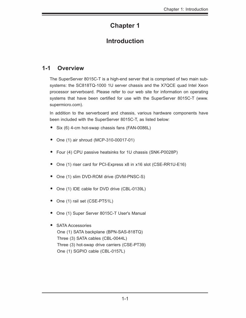
The SuperServer 8015C-T is a high-end server that is comprised of two main sub-systems: the SC818TQ-1000 1U server chassis and the X7QCE quad Intel Xeon processor serverboard. Please refer to our web site for information on operating systems that have been certifi ed for use with the SuperServer 8015C-T (www.supermicro.com).
In addition to the serverboard and chassis, various hardware components have been included with the SuperServer 8015C-T, as listed below:
Six (6) 4-cm hot-swap chassis fans (FAN-0086L)
One (1) air shroud (MCP-310-00017-01)
Four (4) CPU passive heatsinks for 1U chassis (SNK-P0028P)
One (1) riser card for PCI-Express x8 in x16 slot (CSE-RR1U-E16)
One (1) slim DVD-ROM drive (DVM-PNSC-S)
One (1) IDE cable for DVD drive (CBL-0139L)
One (1) rail set (CSE-PT51L)
One (1) Super Server 8015C-T User's Manual
SATA Accessories One (1) SATA backplane (BPN-SAS-818TQ) Three (3) SATA cables (CBL-0044L) Three (3) hot-swap drive carriers (CSE-PT39) One (1) SGPIO cable (CBL-0157L)
•
•
•
•
•
•
•
•
•
Chapter 1: Introduction
1-1
1-2
SUPERSERVER 8015C-T User's Manual
1-2 Serverboard Features
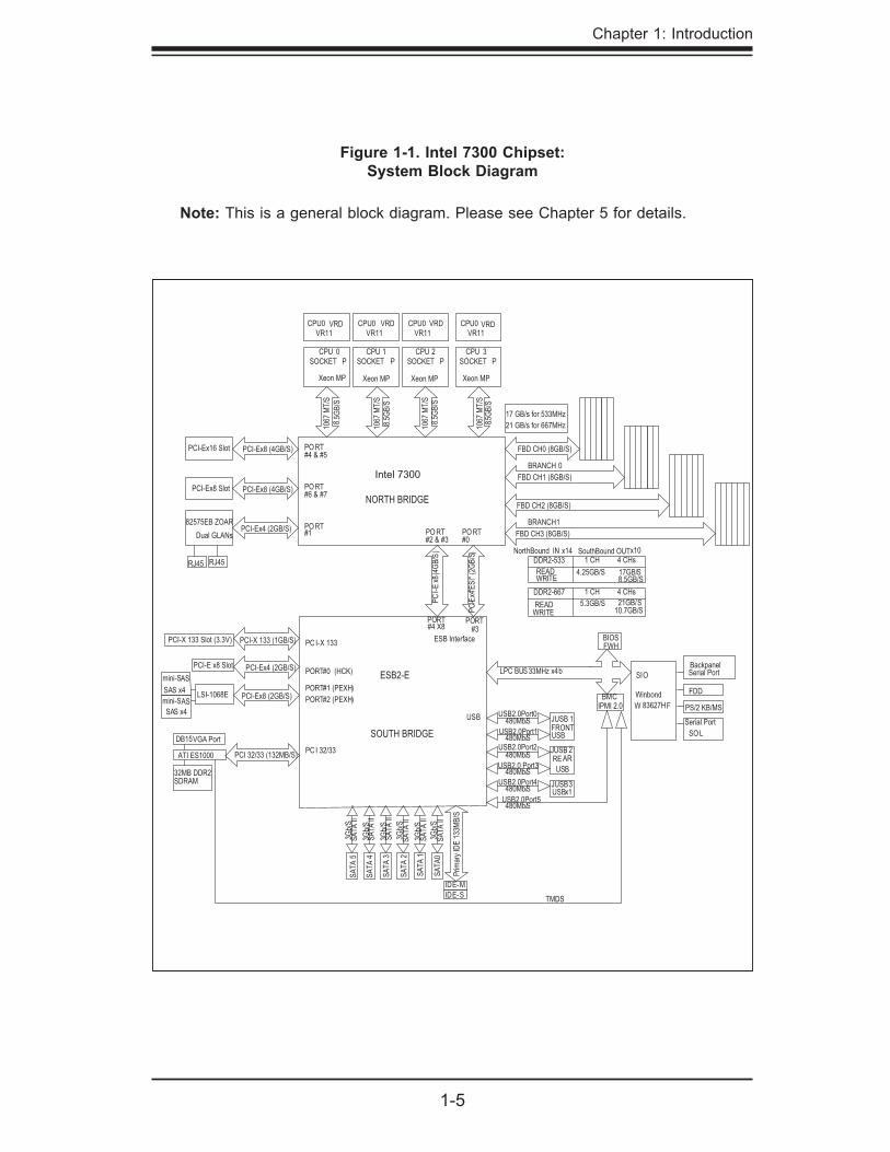
At the heart of the SuperServer 8015C-T lies the X7QCE, a quad processor serverboard based on the Intel 7300 chipset. Below are the main features of the X7QCE. (See Figure 1-1 for a block diagram of the 7300 chipset).
ProcessorsThe X7QCE supports four Intel Xeon MP 7300/7200 sequence processors of the same type (it does not support 130W processors). Please refer to the serverboard description pages on our web site for a complete listing of supported processors (www.supermicro.com).
MemoryThe X7QCE has 24 240-pin DIMM slots that can support up to 192 GB of ECC FBD (Fully Buffered DIMM) DDR2-667/533 SDRAM. Single channel, two-channel interleaved and four-channel interleaved memory all all supported. Modules of the same size and speed should be used. See Chapter 5 Section 5 for details.
Serial ATA A SATA controller is integrated into the South Bridge (ESB2) section of the chipset to provide a six-port Serial ATA subsystem, which is RAID 0, 1, 10 and 5 supported. The Serial ATA drives are hot-swappable units.
Note: The operating system you use must have RAID support to enable the hot-swap capability and RAID function of the Serial ATA drives.
PCI Expansion SlotsThe X7QCE has two PCI-Express x8 slots, one PCI-Express x4 slot and one PCI-X 133 MHz slot.
Onboard Controllers/PortsOne fl oppy drive controller and two onboard ATA/100 controllers are provided to support up to two IDE hard drives or ATAPI devices (one IDE connection is reserved for a Compact Flash card). The color-coded I/O ports include one COM port (an additional COM header is located on the serverboard), a VGA (monitor) port, two USB 2.0 ports, PS/2 mouse and keyboard ports and two Gb Ethernet ports.
ATI Graphics Controller
1-3
Chapter 1: Introduction
The X7QCE features an integrated ATI video controller based on the ES1000 graph-ics chip. The ES1000 was designed specifi cally for servers, featuring low power consumption, high reliability and superior longevity.
IPMIIPMI (Intelligent Platform Management Interface) is a hardware-level interface speci-fi cation that provides remote access, monitoring and administration for Supermicro server platforms. IPMI allows server administrators to view a server’s hardware status remotely, receive an alarm automatically if a failure occurs, and power cycle a system that is non-responsive.
Other FeaturesOther onboard features that promote system health include onboard voltage moni-tors, a chassis intrusion header, auto-switching voltage regulators, chassis and CPU overheat sensors, virus protection and BIOS rescue.
1-4
SUPERSERVER 8015C-T User's Manual
1-3 Server Chassis Features
The following is a general outline of the main features of the SC818TQ-1000 server chassis.
System PowerThe SC818TQ-1000 features a 1000W high-effi ciency power supply with I2C. Power must be removed from the system before servicing or replacing the power supply.
SATA SubsystemThe SC818TQ-1000 chassis was designed to support three SATA hard drives, which are hot-swappable units.
Front Control PanelThe control panel on the SuperServer 8015C-T provides you with system monitor-ing and control. LEDs indicate system power, HDD activity, network activity, system overheat and power supply failure. A main power button and a system reset button are also included. In addition, two USB ports and a COM port have been incorpo-rated into the front of the chassis for convenient access.
I/O BackplaneThe SC818TQ-1000 is an ATX form factor chassis designed to be used in a 1U rackmount confi guration. The I/O backplane includes one COM port, a VGA port, two USB 2.0 ports, PS/2 mouse and keyboard ports and two gigabit Ethernet ports. One standard size PCI expansion card may be added to the system.
Cooling SystemThe SC818TQ-1000 chassis chassis has an innovative cooling design that includes six 4-cm counter-rotating fans located in the middle section of the chassis. The power supply module also includes a cooling fan. All chassis and power supply fans operate continuously. An air shroud channels the airfl ow from the system fans to effi ciently cool the processors and memory.
1-5
Chapter 1: Introduction
Figure 1-1. Intel 7300 Chipset: System Block Diagram
Note: This is a general block diagram. Please see Chapter 5 for details.
SOCKET P SOCKET P SOCKET PCPU 3
SOCKET P
Xeon MP
CPU 2CPU 1CPU 0
NORTH BRIDGE
ESB2-E
SOUTH BRIDGE
1067
MT
/S
1067
MT
/S
1067
MT
/S
1067
MT
/S
CPU0VR11
VRD CPU0VR11
VRD CPU0VR11
VRD CPU0VR11
VRD
PO RT#4 & #5
PO RT
PO RT
#6 & #7
#1 PO RT#2 & #3
PO RT#0
PCI
-E x4
"ES
I" (
2GB
/S)
PC
I-E
x8
(4G
B/S
)
RJ45
FRONT USB
RE AR USB
JUSB3
JUSB 1
PORT
JUSB 2
USB x1
#3PORT#4 X8
USB2.0Port0
USB2.0Port1
USB2.0Port2
USB2.0 Port3
USB2.0Port4
USB2.0Port5
FBD CH0 (8GB/S)
FBD CH1 (8GB/S)
FBD CH2 (8GB/S)
FBD CH3 (8GB/S)
BRANCH 0
BRANCH 1
PORT#0 (HCK)
PORT#1 (PEXH)
PC I-X 133
PC I 32/33
USB
LSI-1068E
ATI ES1000
32MB DDR2SDRAM
DB15VGA Port
480Mb/S
480Mb/S
480Mb/S
480Mb/S
480Mb/S
480Mb/S
IDE-S
IDE-M
17 GB/s for 533MHz
21 GB/s for 667MHz
NorthBound IN x14 SouthBound OUT x10
4.25GB/S 17GB/S
4 CHs1 CH
READWRITE 8.5GB/S
DDR2-533
5.3GB/S 21GB/S
4 CHs1 CH
READWRITE 10.7GB/S
DDR2-667
LPC BUS
BIOS
33MHz x4bSIO
Winbond
W 83627HF
Serial Port
FDD
PS/2 KB/MS
Serial Port
SO L
BMCIPMI 2.0
PCI-X 133 Slot (3.3V)
PORT#2 (PEXH)
PCI-E x8 Slot
mini-SAS
mini-SAS
SAS x4
SAS x4
8.5G
B/S
8.5G
B/S
8.5G
B/S
8 .5G
B/S
PCI-X 133 (1GB/S)
PCI-Ex4 (2GB/S)
PCI-Ex8 (2GB/S)
PCI 32/33 (132MB/S)
PCI-Ex4 (2GB/S)
PCI-Ex8 (4GB/S)
PCI-Ex8 (4GB/S)PCI-Ex16 Slot
PCI-Ex8 Slot
82575EB ZOAR
Dual GLANs
FWHESB Interface
RJ45
Backpanel
Xeon MPXeon MPXeon MP
SA
TA
II3G
b/S
3Gb/
S
3Gb/
S
3Gb/
S
3Gb/
S
3Gb/
S
SA
TA
II
SA
TA
II
SA
TA
II
SA
TA
II
SA
TA
II
SA
TA
0
SA
TA
1
SA
TA
2
SA
TA
3
SA
TA
4
SA
TA
5
Prim
ary
IDE
133
MB
/S
TMDS
Intel 7300
1-6
SUPERSERVER 8015C-T User's Manual
1-4 Contacting Supermicro
HeadquartersAddress: Super Micro Computer, Inc.
980 Rock Ave.
San Jose, CA 95131 U.S.A.
Tel: +1 (408) 503-8000
Fax: +1 (408) 503-8008
Email: [email protected] (General Information)
[email protected] (Technical Support)
Web Site: www.supermicro.com
EuropeAddress: Super Micro Computer B.V.
Het Sterrenbeeld 28, 5215 ML
's-Hertogenbosch, The Netherlands
Tel: +31 (0) 73-6400390
Fax: +31 (0) 73-6416525
Email: [email protected] (General Information)
[email protected] (Technical Support)
[email protected] (Customer Support)
Asia-Pacifi c Address: Super Micro, Taiwan
4F, No. 232-1, Liancheng Rd.
Chung-Ho 235, Taipei County
Taiwan, R.O.C.
Tel: +886-(2) 8226-3990
Fax: +886-(2) 8226-3991
Web Site: www.supermicro.com.tw
Technical Support:
Email: [email protected]
Tel: 886-2-8228-1366, ext.132 or 139
Chapter 2: Server Installation
2-1
Chapter 2
Server Installation
2-1 Overview
This chapter provides a quick setup checklist to get your 8015C-T up and running. Following these steps in the order given should enable you to have the system operational within a minimum amount of time. This quick setup assumes that your system has come to you with the processors and memory preinstalled. If your system is not already fully integrated with a serverboard, processors, system memory etc., please turn to the chapter or section noted in each step for details on installing specifi c components.
2-2 Unpacking the System
You should inspect the box the 8015C-T was shipped in and note if it was damaged in any way. If the server itself shows damage you should fi le a damage claim with the carrier who delivered it.
Decide on a suitable location for the rack unit that will hold the 8015C-T. It should be situated in a clean, dust-free area that is well ventilated. Avoid areas where heat, electrical noise and electromagnetic fi elds are generated. You will also need it placed near a grounded power outlet. Be sure to read the Rack and Server Precautions in the next section.
2-3 Preparing for Setup
The box the 8015C-T was shipped in should include two sets of rail assemblies, two rail mounting brackets and the mounting screws you will need to install the system into the rack. Follow the steps in the order given to complete the installation process in a minimum amount of time. Please read this section in its entirety before you begin the installation procedure outlined in the sections that follow.
2-2
SUPERSERVER 8015C-T User's Manual
Warnings and Precautions!
Rack PrecautionsEnsure that the leveling jacks on the bottom of the rack are fully extended to the fl oor with the full weight of the rack resting on them.
In single rack installation, stabilizers should be attached to the rack. In multiple rack installations, the racks should be coupled together.
Always make sure the rack is stable before extending a component from the rack.
You should extend only one component at a time - extending two or more si-multaneously may cause the rack to become unstable.
Server PrecautionsReview the electrical and general safety precautions in Chapter 4.
Determine the placement of each component in the rack before you install the rails.
Install the heaviest server components on the bottom of the rack fi rst, and then work up.
Use a regulating uninterruptible power supply (UPS) to protect the server from power surges, voltage spikes and to keep your system operating in case of a power failure.
•
•
•
•
•
•
•
•
Choosing a Setup LocationLeave enough clearance in front of the rack to enable you to open the front door completely (~25 inches) and approximately 30 inches of clearance in the back of the rack to allow for suffi cient airfl ow and ease in servicing.
This product is for installation only in a Restricted Access Location (dedicated equipment rooms, service closets and the like).
This product is not suitable for use with visual display work place devices acccording to §2 of the the German Ordinance for Work with Visual Display Units.
•
•
•
! !
Chapter 2: Server Installation
2-3
Allow the hot plug SATA drives and power supply modules to cool before touch-ing them.
Always keep the rack's front door and all panels and components on the servers closed when not servicing to maintain proper cooling.
Rack Mounting Considerations
Ambient Operating TemperatureIf installed in a closed or multi-unit rack assembly, the ambient operating tempera-ture of the rack environment may be greater than the ambient temperature of the room. Therefore, consideration should be given to installing the equipment in an environment compatible with the manufacturer’s maximum rated ambient tempera-ture (Tmra).
Reduced Airfl owEquipment should be mounted into a rack so that the amount of airfl ow required for safe operation is not compromised.
Mechanical LoadingEquipment should be mounted into a rack so that a hazardous condition does not arise due to uneven mechanical loading.
Circuit OverloadingConsideration should be given to the connection of the equipment to the power supply circuitry and the effect that any possible overloading of circuits might have on overcurrent protection and power supply wiring. Appropriate consideration of equipment nameplate ratings should be used when addressing this concern.
Reliable GroundA reliable ground must be maintained at all times. To ensure this, the rack itself should be grounded. Particular attention should be given to power supply connec-tions other than the direct connections to the branch circuit (i.e. the use of power strips, etc.).
•
•

2-4
SUPERSERVER 8015C-T User's Manual
2-4 Installing the System into a Rack
This section provides information on installing the 8015C-T into a rack unit with the rack rails provided. If the system has already been mounted into a rack, you can skip ahead to Sections 2-5 and 2-6. There are a variety of rack units on the market, which may mean the assembly procedure will differ slightly. You should also refer to the installation instructions that came with the rack unit you are using.
Identifying the Sections of the Rack RailsYou should have received two rack rail assemblies in the rack mounting kit. Each assembly consists of two sections: an inner fi xed chassis rail that secures directly to the server chassis and an outer fi xed rack rail that secures directly to the rack itself (see Figure 2-1). Two pairs of short brackets to be used on the front side of the outer rails are also included.
Installing the Inner RailsBoth the left and right side inner rails have been pre-attached to the chassis. Pro-ceed to the next step.
Figure 2-1. Identifying the Sections of the Rack Rails (right side rail shown)
Chapter 2: Server Installation
2-5
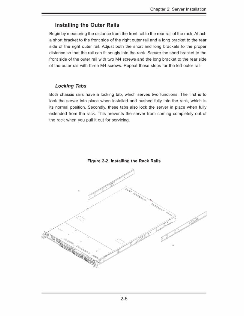
Installing the Outer RailsBegin by measuring the distance from the front rail to the rear rail of the rack. Attach a short bracket to the front side of the right outer rail and a long bracket to the rear side of the right outer rail. Adjust both the short and long brackets to the proper distance so that the rail can fi t snugly into the rack. Secure the short bracket to the front side of the outer rail with two M4 screws and the long bracket to the rear side of the outer rail with three M4 screws. Repeat these steps for the left outer rail.
Locking TabsBoth chassis rails have a locking tab, which serves two functions. The fi rst is to lock the server into place when installed and pushed fully into the rack, which is its normal position. Secondly, these tabs also lock the server in place when fully extended from the rack. This prevents the server from coming completely out of the rack when you pull it out for servicing.
Figure 2-2. Installing the Rack Rails
2-6
SUPERSERVER 8015C-T User's Manual
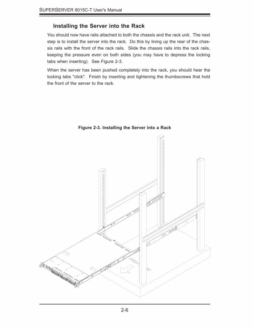
Figure 2-3. Installing the Server into a Rack
Installing the Server into the RackYou should now have rails attached to both the chassis and the rack unit. The next step is to install the server into the rack. Do this by lining up the rear of the chas-sis rails with the front of the rack rails. Slide the chassis rails into the rack rails, keeping the pressure even on both sides (you may have to depress the locking tabs when inserting). See Figure 2-3.
When the server has been pushed completely into the rack, you should hear the locking tabs "click". Finish by inserting and tightening the thumbscrews that hold the front of the server to the rack.
Chapter 2: Server Installation
2-7
2-5 Checking the Serverboard Setup
After you install the 8015C-T in the rack, you will need to open the top cover to make sure the serverboard is properly installed and all the connections have been made.
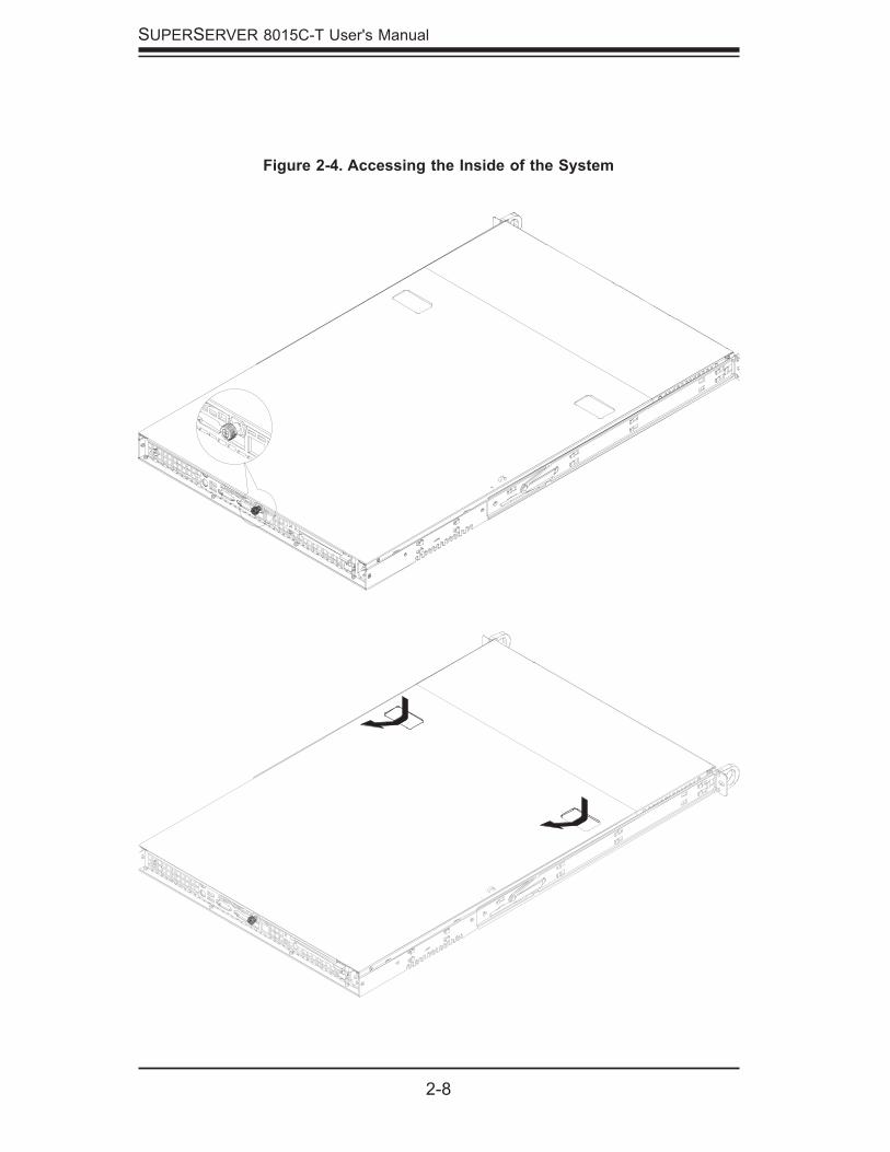
Accessing the inside of the System (see Figure 2-4)
First, release the retention screws that secure the system to the rack.
Grasp the two handles on either side and pull the system straight out until it locks (you will hear a "click").
Next, release the thumbscrew at the middle rear of the top cover. Then de-press the two buttons on the top of the chassis to release the top cover.
Push the cover away from you (toward the rear of the chassis) until it stops. You can then lift the top cover from the chassis to gain full access to the inside of the server.
To remove the system from the rack completely, depress the locking tabs in the chassis rails (push the right-side tab down and the left-side tab up) to continue to pull the system out past the locked position.
Checking the Components and Setup
You may up to four processors already installed in the serverboard. Each processor needs its own heatsink. See Chapter 5 for instructions on proces-sor and heatsink installation.
Your server system may have come with system memory already installed. Make sure all DIMMs are fully seated in their slots. For details on adding system memory, refer to Chapter 5.
If desired, you can install an add-on card to the system. See Chapter 5 for details on installing PCI add-on cards.
Make sure all power and data cables are properly connected and not blocking the chassis airfl ow. See Chapter 5 for details on cable connections.
1.
2.
3.
4.
5.
1.
2.
3.
4.
2-8
SUPERSERVER 8015C-T User's Manual
Figure 2-4. Accessing the Inside of the System
Chapter 2: Server Installation
2-9
2-6 Preparing to Power On
Next, you should check to make sure the peripheral drives and the SATA drives and SATA backplane have been properly installed and all connections have been made.
Checking the Drives
All drives are accessable from the front of the server. For servicing the DVD-ROM and fl oppy drives, you will need to remove the top chassis cover. The SATA disk drives can be installed and removed from the front of the chassis without removing the top chassis cover.
A slim DVD-ROM and fl oppy drive should be preinstalled in your server. Refer to Chapter 6 if you need to reinstall a DVD-ROM and/or fl oppy disk drive to the system.
Depending upon your system's confi guration, your system may have one or more drives already installed. If you need to install SATA drives, please refer to Chapter 6.
Checking the Airfl ow
Airfl ow is provided by six sets of 4-cm fans (each set of fans consists of two fans that are mounted back to back) and an air shroud. The system compo-nent layout was carefully designed to direct suffi cient cooling airfl ow to the components that generate the most heat.
Note that all power and data cables have been routed in such a way that they do not block the airfl ow generated by the fans.
Providing Power
Plug the power cords from the power supplies unit into a high-quality power strip that offers protection from electrical noise and power surges.
It is recommended that you use an uninterruptible power supply (UPS).
Finally, depress the power on button on the front of the chassis.
1.
2.
3.
1.
2.
1.
2.
3.

2-10
SUPERSERVER 8015C-T User's Manual
Notes
Chapter 3: System Interface
3-1
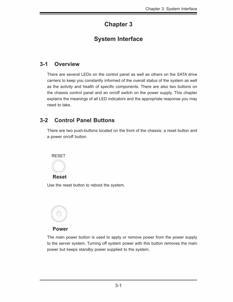
PowerThe main power button is used to apply or remove power from the power supply to the server system. Turning off system power with this button removes the main power but keeps standby power supplied to the system.
Chapter 3
System Interface
3-1 Overview
There are several LEDs on the control panel as well as others on the SATA drive carriers to keep you constantly informed of the overall status of the system as well as the activity and health of specifi c components. There are also two buttons on the chassis control panel and an on/off switch on the power supply. This chapter explains the meanings of all LED indicators and the appropriate response you may need to take.
3-2 Control Panel Buttons
There are two push-buttons located on the front of the chassis: a reset button and a power on/off button.
ResetUse the reset button to reboot the system.
3-2
SUPERSERVER 8015C-T User's Manual
2
1
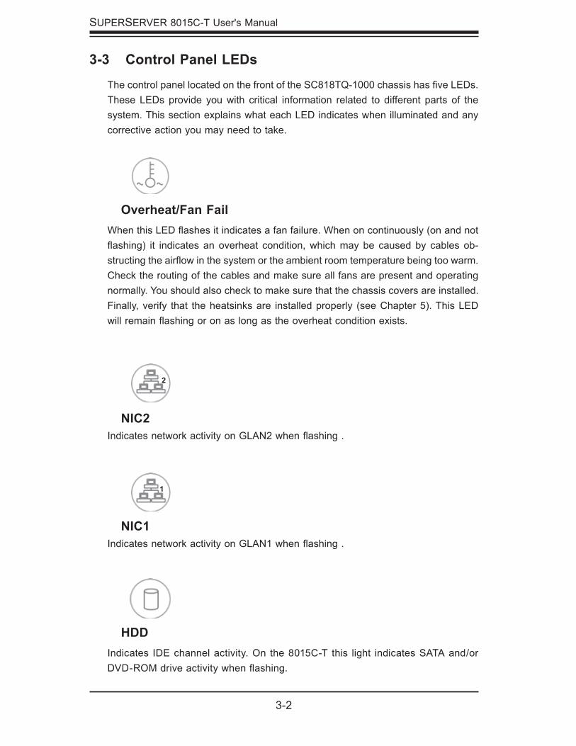
NIC2Indicates network activity on GLAN2 when fl ashing .
3-3 Control Panel LEDs
The control panel located on the front of the SC818TQ-1000 chassis has fi ve LEDs. These LEDs provide you with critical information related to different parts of the system. This section explains what each LED indicates when illuminated and any corrective action you may need to take.
Overheat/Fan FailWhen this LED fl ashes it indicates a fan failure. When on continuously (on and not fl ashing) it indicates an overheat condition, which may be caused by cables ob-structing the airfl ow in the system or the ambient room temperature being too warm. Check the routing of the cables and make sure all fans are present and operating normally. You should also check to make sure that the chassis covers are installed. Finally, verify that the heatsinks are installed properly (see Chapter 5). This LED will remain fl ashing or on as long as the overheat condition exists.
NIC1Indicates network activity on GLAN1 when fl ashing .
HDDIndicates IDE channel activity. On the 8015C-T this light indicates SATA and/or DVD-ROM drive activity when fl ashing.
Chapter 3: System Interface
3-3
3-4 SATA Drive Carrier LEDs
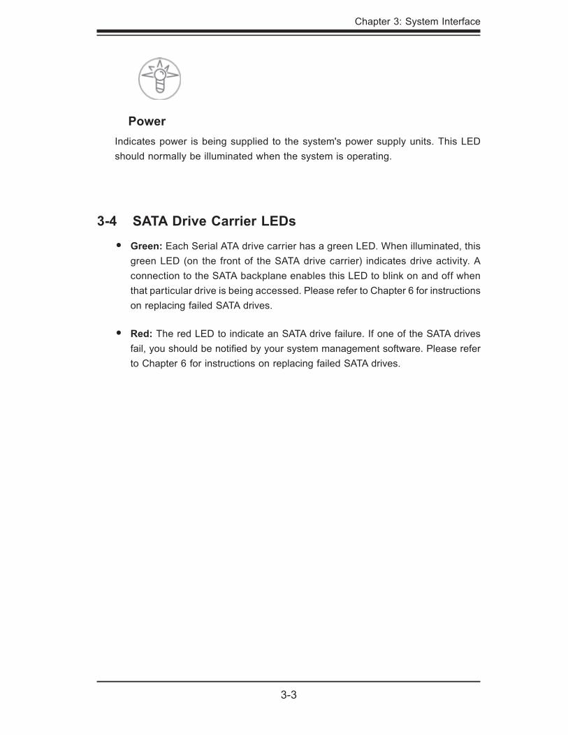
Green: Each Serial ATA drive carrier has a green LED. When illuminated, this green LED (on the front of the SATA drive carrier) indicates drive activity. A connection to the SATA backplane enables this LED to blink on and off when that particular drive is being accessed. Please refer to Chapter 6 for instructions on replacing failed SATA drives.
Red: The red LED to indicate an SATA drive failure. If one of the SATA drives fail, you should be notifi ed by your system management software. Please refer to Chapter 6 for instructions on replacing failed SATA drives.
•
•
PowerIndicates power is being supplied to the system's power supply units. This LED should normally be illuminated when the system is operating.

3-4
SUPERSERVER 8015C-T User's Manual
Notes
Chapter 4: System Safety
4-1
Chapter 4
System Safety
4-1 Electrical Safety Precautions
!
Basic electrical safety precautions should be followed to protect yourself from harm and the SuperServer 8015C-T from damage:
Be aware of the locations of the power on/off switch on the chassis as well as the room's emergency power-off switch, disconnection switch or electrical outlet. If an electrical accident occurs, you can then quickly remove power from the system.
Do not work alone when working with high voltage components.
Power should always be disconnected from the system when removing or in-stalling main system components, such as the serverboard, memory modules and fl oppy drive. When disconnecting power, you should fi rst power down the system with the operating system fi rst and then unplug the power cords of all the power supply units in the system.
When working around exposed electrical circuits, another person who is familiar with the power-off controls should be nearby to switch off the power if neces-sary.
Use only one hand when working with powered-on electrical equipment. This is to avoid making a complete circuit, which will cause electrical shock. Use extreme caution when using metal tools, which can easily damage any electrical components or circuit boards they come into contact with.
Do not use mats designed to decrease static electrical discharge as protection from electrical shock. Instead, use rubber mats that have been specifi cally designed as electrical insulators.
The power supply power cords must include a grounding plug and must be plugged into grounded electrical outlets.
•
•
•
•
•
•
•
SUPERSERVER 8015C-T User's Manual
4-2
4-2 General Safety Precautions
Follow these rules to ensure general safety:
Keep the area around the SuperServer 8015C-T clean and free of clutter.
The SuperServer 8015C-T weighs approximately 43 lbs. (19.5 kg) when fully loaded. When lifting the system, two people at either end should lift slowly with their feet spread out to distribute the weight. Always keep your back straight and lift with your legs.
Place the chassis top cover and any system components that have been re-moved away from the system or on a table so that they won't accidentally be stepped on.
While working on the system, do not wear loose clothing such as neckties and unbuttoned shirt sleeves, which can come into contact with electrical circuits or be pulled into a cooling fan.
Remove any jewelry or metal objects from your body, which are excellent metal conductors that can create short circuits and harm you if they come into contact with printed circuit boards or areas where power is present.
•
•
•
•
•
!
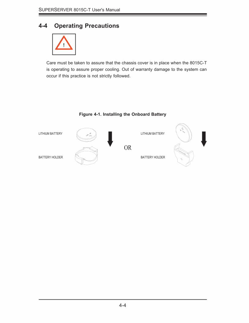
Serverboard Battery: CAUTION - There is a danger of explosion if the onboard battery is installed upside down, which will reverse its polarites (see Figure 4-1). This battery must be replaced only with the same or an equivalent type recommended by the manufacturer. Dispose of used batteries according to the manufacturer's instructions.
CD-ROM Laser: CAUTION - this server may have come equipped with a CD-ROM drive. To prevent direct exposure to the laser beam and hazardous radia-tion exposure, do not open the enclosure or use the unit in any unconventional way.
Mainboard replaceable soldered-in fuses: Self-resetting PTC (Positive Tempera-ture Coeffi cient) fuses on the mainboard must be replaced by trained service technicians only. The new fuse must be the same or equivalent as the one replaced. Contact technical support for details and support.
•
•
•
Chapter 4: System Safety
4-3
4-3 ESD Precautions
Electrostatic discharge (ESD) is generated by two objects with different electrical charges coming into contact with each other. An electrical discharge is created to neutralize this difference, which can damage electronic com ponents and printed circuit boards. The following measures are generally suffi cient to neutralize this difference before contact is made to protect your equipment from ESD:
Use a grounded wrist strap designed to prevent static discharge.
Keep all components and printed circuit boards (PCBs) in their antistatic bags until ready for use.
Touch a grounded metal object before removing the board from the antistatic bag.
Do not let components or PCBs come into contact with your clothing, which may retain a charge even if you are wearing a wrist strap.
Handle a board by its edges only; do not touch its components, peripheral chips, memory modules or contacts.
When handling chips or modules, avoid touching their pins.
Put the serverboard and peripherals back into their antistatic bags when not in use.
For grounding purposes, make sure your computer chassis provides excellent conductivity between the power supply, the case, the mounting fasteners and the serverboard.
•
•
•
•
•
•
•
•
!
After accessing the inside of the system, close the system back up and secure it to the rack unit with the retention screws after ensuring that all connections have been made.
•
SUPERSERVER 8015C-T User's Manual
4-4
4-4 Operating Precautions
Care must be taken to assure that the chassis cover is in place when the 8015C-T is operating to assure proper cooling. Out of warranty damage to the system can occur if this practice is not strictly followed.
!
Figure 4-1. Installing the Onboard Battery
LITHIUM BATTERY
BATTERY HOLDER BATTERY HOLDER
LITHIUM BATTERY
OR
Chapter 5: Advanced Serverboard Setup
5-1
Chapter 5
Advanced Serverboard Setup
This chapter covers the steps required to install the X7QCE serverboard into the chassis, connect the data and power cables and install add-on cards. All serverboard jumpers and connections are also described. A layout and quick refer-ence chart are included in this chapter for your reference. Remember to completely close the chassis when you have fi nished working with the serverboard to better cool and protect the system.
5-1 Handling the Serverboard
Electrostatic discharge (ESD) can damage electronic com ponents. To prevent dam-age to any printed circuit boards (PCBs), it is important to handle them very carefully (see previous chapter). To prevent the serverboard from bending, keep one hand under the center of the board to support it when handling. The following measures are generally suffi cient to protect your equipment from electric static discharge.
Precautions
Use a grounded wrist strap designed to prevent Electrostatic Discharge (ESD).
Touch a grounded metal object before removing any board from its antistatic bag.
Handle a board by its edges only; do not touch its components, peripheral chips, memory modules or gold contacts.
When handling chips or modules, avoid touching their pins.
Put the serverboard, add-on cards and peripherals back into their antistatic bags when not in use.
For grounding purposes, make sure your computer chassis provides excellent conductivity between the power supply, the case, the mounting fasteners and the serverboard.
•
•
•
•
•
•
5-2
SUPERSERVER 8015C-T User's Manual
UnpackingThe serverboard is shipped in antistatic packaging to avoid electrical static dis-charge. When unpacking the board, make sure the person handling it is static protected.
5-2 Serverboard Installation
This section explains the fi rst step of physically mounting the X7QCE into the SC818TQ-1000 chassis. Following the steps in the order given will eliminate the most common problems encountered in such an installation. To remove the serverboard, follow the procedure in reverse order.
Installing to the Chassis
Access the inside of the system by removing the screws from the back lip of the top cover of the chassis, then pull the cover off.
The X7QCE requires a chassis big enough to support a 16" x 14.3" serverboard, such as Supermicro's SC818TQ-1000.
Make sure that the I/O ports on the serverboard align properly with their respective holes in the I/O shield at the back of the chassis.
Carefully mount the serverboard to the serverboard tray by aligning the board holes with the raised metal standoffs that are visible in the chassis.
Insert screws into all the mounting holes on your serverboard that line up with the standoffs and tighten until snug (if you screw them in too tight, you might strip the threads). Metal screws provide an electrical contact to the serverboard ground to provide a continuous ground for the system.
Finish by replacing the top cover of the chassis.
1.
2.
3.
4.
5.
6.
Chapter 5: Advanced Serverboard Setup
5-3
5-3 Connecting Cables
Now that the serverboard is installed, the next step is to connect the cables to the board. These include the data (ribbon) cables for the peripherals and control panel and the power cables.
Connecting Data CablesThe ribbon cables used to transfer data from the peripheral devices have been care-fully routed to prevent them from blocking the fl ow of cooling air that moves through the system from front to back. If you need to disconnect any of these cables, you should take care to keep them routed as they were originally after reconnecting them (make sure the red wires connect to the pin 1 locations). The following data cables (with their locations noted) should be connected. (See the layout on page 5-9 for connector locations.)
SATA drive data cable (SATA#0 ~ 2)
Control Panel cable (JF1)
DVD-ROM drive cable (J3)
Important! Make sure the the cables do not come into contact with the fans.
Connecting Power CablesThe X7QCE has a 24-pin primary power supply connector (JPW1) for connection to the ATX power supply. In addition, there is an 8-pin secondary power connector (JPW2) that also must be connected to your power supply (via a 4-pin connector). See Section 5-9 for power connector pin defi nitions.
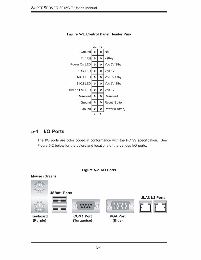
Connecting the Control PanelJF1 contains header pins for various front control panel connectors. See Figure 5-1 for the pin locations of the various front control panel buttons and LED indicators.
All JF1 wires have been bundled into a single ribbon cable to simplify this connec-tion. Make sure the red wire plugs into pin 1 as marked on the board. The other end connects to the Control Panel PCB board, located just behind the system status LEDs on the chassis. See Chapter 5 for details and pin descriptions.
•
•
•
5-4
SUPERSERVER 8015C-T User's Manual
5-4 I/O Ports
The I/O ports are color coded in conformance with the PC 99 specifi cation. See Figure 5-2 below for the colors and locations of the various I/O ports.
Figure 5-1. Control Panel Header Pins
Mouse (Green)
Keyboard(Purple)
COM1 Port(Turquoise)
VGA Port(Blue)
Figure 5-2. I/O Ports
NMI
x (Key)
Vcc 5V Stby
Vcc 3V
Vcc 3V Stby
Vcc 3V Stby
Vcc 3V
Reserved
Reset (Button)
Power (Button)
Ground
x (Key)
Power On LED
HDD LED
NIC1 LED
NIC2 LED
OH/Fan Fail LED
Reserved
Ground
Ground 2 1
20 19
USB0/1 PortsJLAN1/2 Ports
Chapter 5: Advanced Serverboard Setup
5-5
5-5 Installing the Processor and Heatsink
!
Avoid placing direct pressure to the top of the processor package. Always remove the power cord fi rst before adding, removing or changing any hardware components.
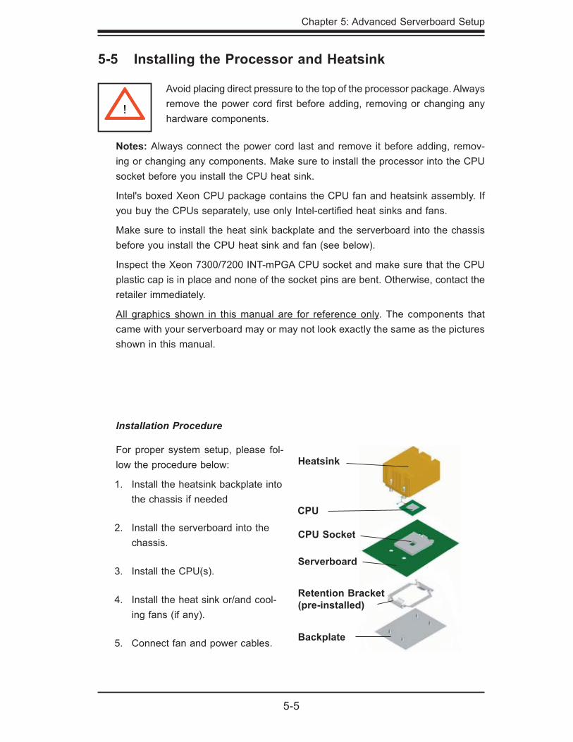
Installation Procedure
For proper system setup, please fol-low the procedure below:
Install the heatsink backplate into the chassis if needed
Install the serverboard into the chassis.
Install the CPU(s).
Install the heat sink or/and cool-ing fans (if any).
Connect fan and power cables.
1.
2.
3.
4.
5. Backplate
Retention Bracket (pre-installed)
Serverboard
CPU Socket
CPU
Heatsink
Notes: Always connect the power cord last and remove it before adding, remov-ing or changing any components. Make sure to install the processor into the CPU socket before you install the CPU heat sink.
Intel's boxed Xeon CPU package contains the CPU fan and heatsink assembly. If you buy the CPUs separately, use only Intel-certifi ed heat sinks and fans.
Make sure to install the heat sink backplate and the serverboard into the chassis before you install the CPU heat sink and fan (see below).
Inspect the Xeon 7300/7200 INT-mPGA CPU socket and make sure that the CPU plastic cap is in place and none of the socket pins are bent. Otherwise, contact the retailer immediately.
All graphics shown in this manual are for reference only. The components that came with your serverboard may or may not look exactly the same as the pictures shown in this manual.
5-6
SUPERSERVER 8015C-T User's Manual
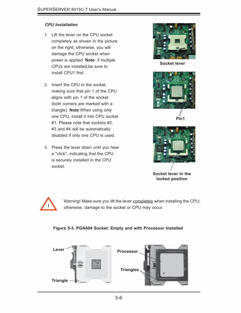
CPU Installation
Lift the lever on the CPU socket completely as shown in the picture on the right; otherwise, you will damage the CPU socket when power is applied. Note: if multiple CPUs are installed,be sure to install CPU1 fi rst.
Insert the CPU in the socket, making sure that pin 1 of the CPU aligns with pin 1 of the socket (both corners are marked with a triangle). Note:When using only one CPU, install it into CPU socket #1. Please note that sockets #2, #3 and #4 will be automatically disabled if only one CPU is used.
Press the lever down until you hear a *click*, indicating that the CPU is securely installed in the CPU socket.
1.
2.
3.
Socket lever
Pin1
Socket lever in the locked position
Figure 5-3. PGA604 Socket: Empty and with Processor Installed
Lever Processor
Triangle
Triangles
Warning! Make sure you lift the lever completely when installing the CPU; otherwise, damage to the socket or CPU may occur.!
Chapter 5: Advanced Serverboard Setup
5-7
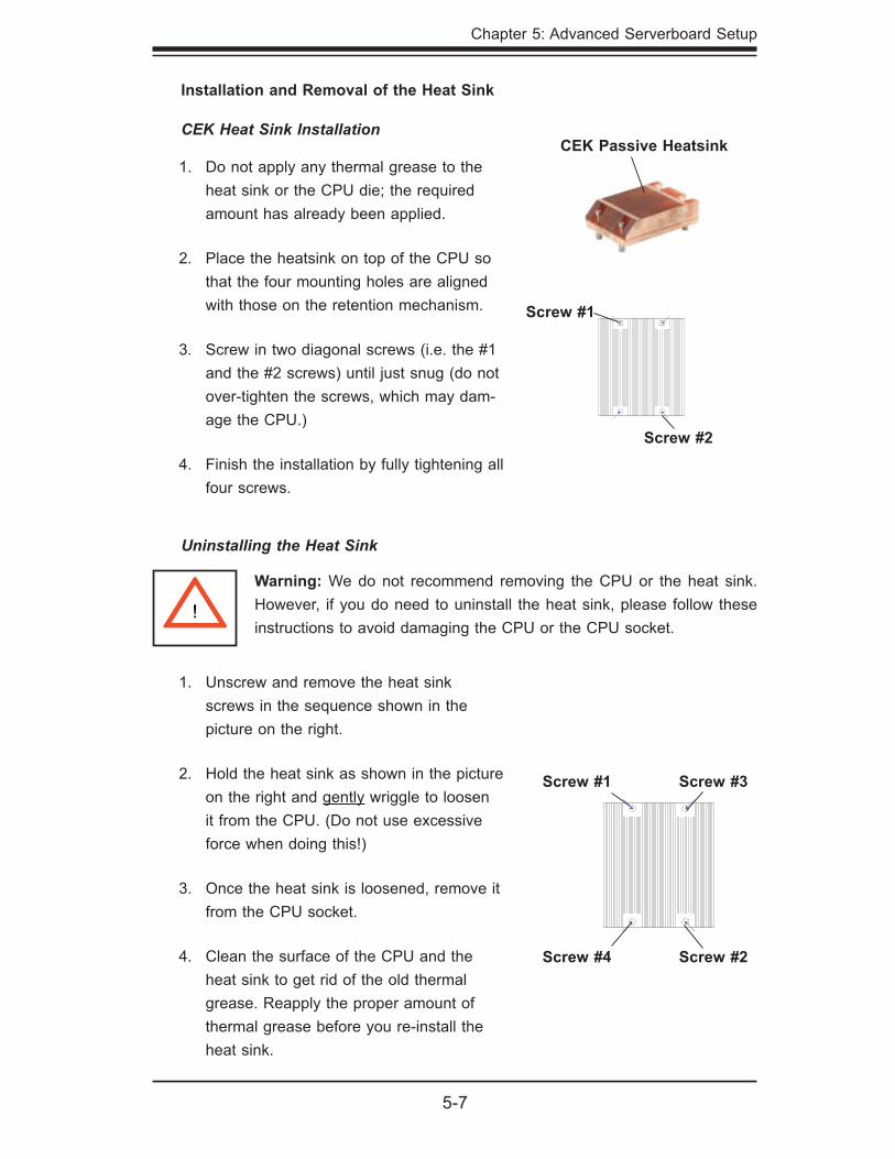
CEK Heat Sink Installation
Do not apply any thermal grease to the heat sink or the CPU die; the required amount has already been applied.
Place the heatsink on top of the CPU so that the four mounting holes are aligned with those on the retention mechanism.
Screw in two diagonal screws (i.e. the #1 and the #2 screws) until just snug (do not over-tighten the screws, which may dam-age the CPU.)
Finish the installation by fully tightening all four screws.
1.
2.
3.
4.
Warning: We do not recommend removing the CPU or the heat sink. However, if you do need to uninstall the heat sink, please follow these instructions to avoid damaging the CPU or the CPU socket.
Installation and Removal of the Heat Sink
CEK Passive Heatsink
Uninstalling the Heat Sink
Unscrew and remove the heat sink screws in the sequence shown in the picture on the right.
Hold the heat sink as shown in the picture on the right and gently wriggle to loosen it from the CPU. (Do not use excessive force when doing this!)
Once the heat sink is loosened, remove it from the CPU socket.
Clean the surface of the CPU and the heat sink to get rid of the old thermal grease. Reapply the proper amount of thermal grease before you re-install the heat sink.
1.
2.
3.
4.
Screw #1
Screw #2
!
Screw #1
Screw #2
Screw #3
Screw #4
5-8
SUPERSERVER 8015C-T User's Manual
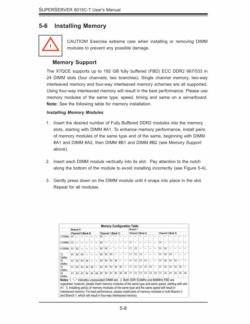
Memory SupportThe X7QCE supports up to 192 GB fully buffered (FBD) ECC DDR2 667/533 in 24 DIMM slots (four channels, two branches). Single channel memory, two-way interleaved memory and four-way interleaved memory schemes are all supported. Using four-way interleaved memory will result in the best performance. Please use memory modules of the same type, speed, timing and same on a serverboard. Note: See the following table for memory installation.
Installing Memory Modules
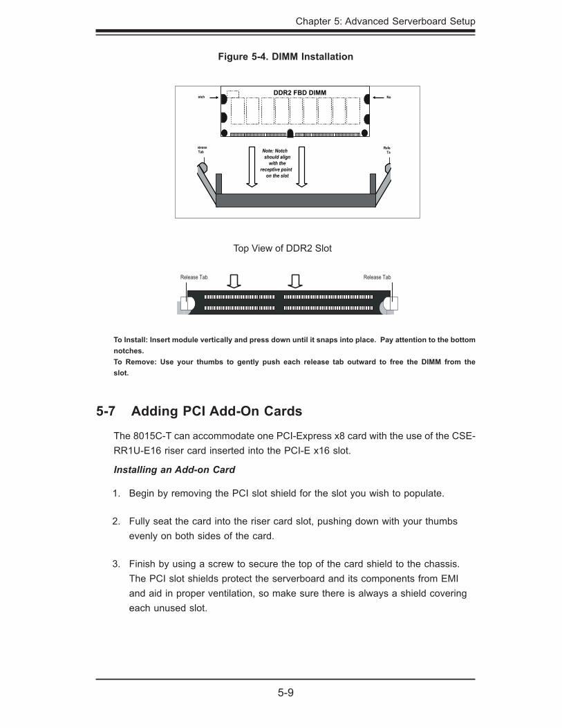
Insert the desired number of Fully Buffered DDR2 modules into the memory slots, starting with DIMM #A1. To enhance memory performance, install pairs of memory modules of the same type and of the same, beginning with DIMM #A1 and DIMM #A2, then DIMM #B1 and DIMM #B2 (see Memory Support above).
Insert each DIMM module vertically into its slot. Pay attention to the notch along the bottom of the module to avoid installing incorrectly (see Figure 5-4).
Gently press down on the DIMM module until it snaps into place in the slot. Repeat for all modules.
1.
2.
3.
!CAUTION! Exercise extreme care when installing or removing DIMM modules to prevent any possible damage.
5-6 Installing Memory
Memory Configuration Table Branch 0 Branch 1 Channel 0 (Bank 0) Channel 1 (Bank 1) Channel 2 (Bank 2) Channel 3 (Bank 3)
2 DIMMs A1 --- --- --- --- --- B1 --- --- --- --- --- --- --- --- --- --- --- --- --- --- --- --- ---
4 DIMMs A1 --- --- --- --- --- B1 --- --- --- --- --- C1 --- --- --- --- --- D1 --- --- --- --- ---
8 DIMMs A1 A2 --- --- --- --- B1 B2 --- --- --- --- C1 C2 --- --- --- --- D1 D2 --- --- --- ---
12DIMMs
A1 A2 A3 --- --- --- B1 B2 B3 --- --- --- C1 C2 C3 --- --- --- D1 D2 D3 --- --- ---
16DIMMs
A1 A2 A3 A4 --- --- B1 B2 B3 B4 --- --- C1 C2 C3 C4 --- --- D1 D2 D3 D4 --- ---
18DIMMs
A1 A2 A3 A4 A5 --- B1 B2 B3 B4 B5 --- C1 C2 C3 C4 C5 --- D1 D2 D3 D4 D5 ---
24DIMMs
A1 A2 A3 A4 A5 A6 B1 B2 B3 B4 B5 B6 C1 C2 C3 C4 C5 C6 D1 D2 D3 D4 D5 D6
Notes: 1. “---“ indicates unpopulated DIMM slot. 2. Both DDR 533MHz and 668MHz FBD are supported; however, please insert memory modules of the same type and same speed, starting with slot A1. 3. Installing pair(s) of memory modules of the same type and the same speed will result in interleaved memory. For best performance, please install pairs of memory modules in both Branch 0 and Branch 1, which will result in four-way interleaved memory.
Chapter 5: Advanced Serverboard Setup
5-9
To Install: Insert module vertically and press down until it snaps into place. Pay attention to the bottom notches. To Remove: Use your thumbs to gently push each release tab outward to free the DIMM from the slot.
Figure 5-4. DIMM Installation
5-7 Adding PCI Add-On Cards
The 8015C-T can accommodate one PCI-Express x8 card with the use of the CSE-RR1U-E16 riser card inserted into the PCI-E x16 slot.
Installing an Add-on Card
Begin by removing the PCI slot shield for the slot you wish to populate.
Fully seat the card into the riser card slot, pushing down with your thumbs evenly on both sides of the card.
Finish by using a screw to secure the top of the card shield to the chassis. The PCI slot shields protect the serverboard and its components from EMI and aid in proper ventilation, so make sure there is always a shield covering each unused slot.
1.
2.
3.
DDR2 FBD DIMM
5-10
SUPERSERVER 8015C-T User's Manual
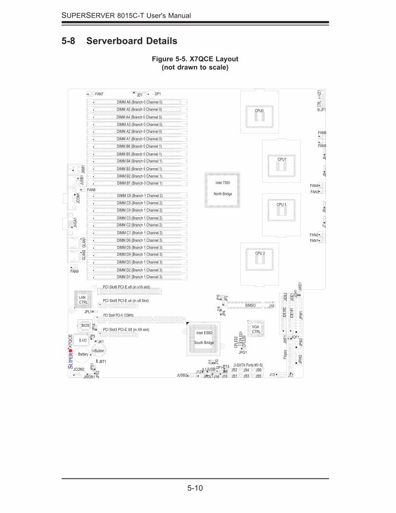
Figure 5-5. X7QCE Layout(not drawn to scale)
5-8 Serverboard Details
PCI Slot4 PCI-X 133MHz
JVG
A1
JCO
M1
J19
J13
JCOM2
FAN7
FAN5
FAN8FAN4
FAN6
FAN2
FAN9
J17
JPS
1
JPL1
JP14
JPG1
JP15
J16 J15JPS
2
JK1
JAR
JP13
JWOR1
J11
JL1
JP5 JCF1
J14
JP4
JP2
JUSB2
J7J9
J8J6
LE1
CP
LED
2
CP
LED
1C
PLE
D0
JD1
JID
E1
JID
E2
JKM
1
JPW
2JP
W3
JUS
B1
JWF
1
SP1
JBT1
JWOL1
J12J3P1
JS6
JS5
JS4
JS3
JS2
JS1
PCI Slot5 PCI-E x4 (in x8 Slot)
J10
FAN3
VGA
CTRL
S I/O
JPW
1
FAN1
JF1
LAN
CTRL
DIMM A1 (Branch 0 Channel 0)
DIMM A2 (Branch 0 Channel 0)
DIMM A3 (Branch 0 Channel 0)
DIMM A4 (Branch 0 Channel 0)
DIMM A5 (Branch 0 Channel 0)
DIMM A6 (Branch 0 Channel 0)
DIMM B1 (Branch 0 Channel 1)
DIMM B2 (Branch 0 Channel 1)
DIMM B3 (Branch 0 Channel 1)
DIMM B4 (Branch 0 Channel 1)
DIMM B5 (Branch 0 Channel 1)
DIMM B6 (Branch 0 Channel 1)
DIMM C1 (Branch 1 Channel 2)
DIMM C2 (Branch 1 Channel 2)
DIMM D1 (Branch 1 Channel 3)
DIMM D2 (Branch 1 Channel 3)
DIMM D3 (Branch 1 Channel 3)
DIMM D4 (Branch 1 Channel 3)
DIMM D5 (Branch 1 Channel 3)
DIMM D6 (Branch 1 Channel 3)
(I-SATA Ports #0~5)
BIOS
Intel ESB2
South Bridge
JWD
1JO
H1
DIMM C3 (Branch 1 Channel 2)
DIMM C4 (Branch 1 Channel 2)
DIMM C5 (Branch 1 Channel 2)
DIMM C6 (Branch 1 Channel 2)
JUSB
I-Button
IDE
1#1
IDE
1#2
SIMSO
Battery
PCI Slot3 PCI-E X8 (in X8 slot)
PCI Slot6 PCI-E x8 (in x16 slot)
GLA
N2
GLA
N1
Flo
ppy
CPU1
CPU0
CPU 3
CPU 2
Intel 7300
North Bridge
X7Q
CE
FP C
TRL
Chapter 5: Advanced Serverboard Setup
5-11
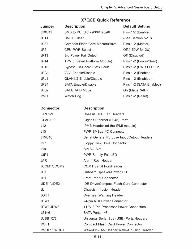
X7QCE Quick ReferenceJumper Description Default SettingJ10/J11 SMB to PCI Slots #3/#4/#5/#6 Pins 1/2 (Enabled)
JBT1 CMOS Clear (See Section 5-10)
JCF1 Compact Flash Card Master/Slave Pins 1-2 (Master)
JP5 CPU PWR Select Off (150W for 2U)
JP13 3rd Power Fail Detect Off (Disabled)
JP14 TPM (Trusted Platform Module) Pins 1-2 (Force-Clear)
JP15 Bypass On-Board PWR Fault Pins 1-2 (PWR LED On)
JPG1 VGA Enable/Disable Pins 1-2 (Enabled)
JPL1 GLAN1/2 Enable/Disable Pins 1-2 (Enabled)
JPS1 SATA Enable/Disable Pins 1-2 (SATA Enabled)
JPS2 SATA RAID Mode On (MegaRAID)
JWD Watch Dog Pins 1-2 (Reset)
Connector DescriptionFAN 1-9 Chassis/CPU Fan Headers
GLAN1/2 Gigabit Ethernet (RJ45) Ports
J12 IPMB Header (of the IPMI module)
J13 PWR SMBus I2C Connector
J15/J16 Serial General Purpose Input/Output Headers
J17 Floppy Disk Drive Connector
J19 SIMSO Slot
J3P1 PWR Supply Fail LED
JAR Alarm Rest Header
JCOM1/JCOM2 COM1 Serial Port/Header
JD1 Onboard Speaker/Power LED
JF1 Front Panel Connector
JIDE1/JIDE2 IDE Drive/Compact Flash Card Connector
JL1 Chassis Intrusion Header
JOH1 Overheat Warning Header
JPW1 24-pin ATX Power Connector
JPW2/JPW3 +12V 8-Pin Processor Power Connectors
JS1~6 SATA Ports 1~6
JUSB1/2/3 Universal Serial Bus (USB) Ports/Headers
JWF1 Compact Flash Card Power Connector
JWOL1/JWOR1 Wake-On-LAN Header/Wake-On-Ring Header
5-12
SUPERSERVER 8015C-T User's Manual
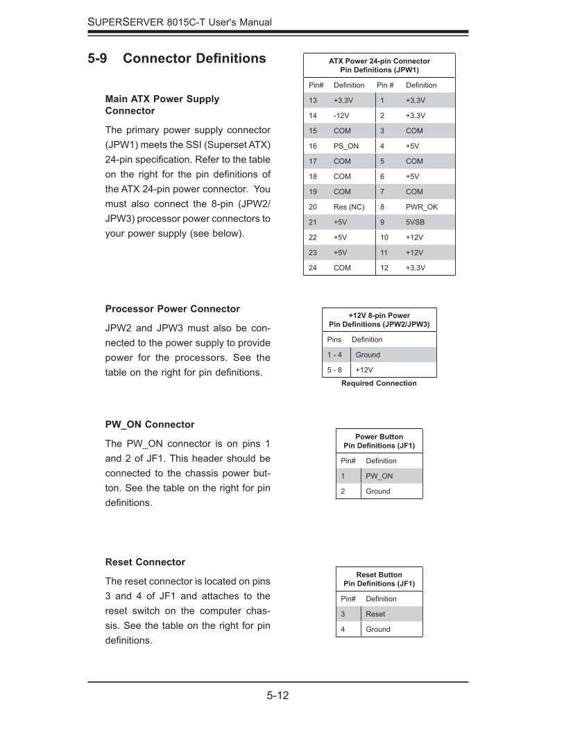
Reset Connector
The reset connector is located on pins 3 and 4 of JF1 and attaches to the reset switch on the computer chas-sis. See the table on the right for pin defi nitions.
PW_ON Connector
The PW_ON connector is on pins 1 and 2 of JF1. This header should be connected to the chassis power but-ton. See the table on the right for pin defi nitions.
5-9 Connector Defi nitions
Required Connection
+12V 8-pin PowerPin Defi nitions (JPW2/JPW3)
Pins Defi nition
1 - 4 Ground
5 - 8 +12V
ATX Power 24-pin ConnectorPin Defi nitions (JPW1)
Pin# Defi nition Pin # Defi nition
13 +3.3V 1 +3.3V
14 -12V 2 +3.3V
15 COM 3 COM
16 PS_ON 4 +5V
17 COM 5 COM
18 COM 6 +5V
19 COM 7 COM
20 Res (NC) 8 PWR_OK
21 +5V 9 5VSB
22 +5V 10 +12V
23 +5V 11 +12V
24 COM 12 +3.3V
Reset ButtonPin Defi nitions (JF1)
Pin# Defi nition
3 Reset
4 Ground
Power ButtonPin Defi nitions (JF1)
Pin# Defi nition
1 PW_ON
2 Ground
Processor Power Connector
JPW2 and JPW3 must also be con-nected to the power supply to provide power for the processors. See the table on the right for pin defi nitions.
Main ATX Power Supply Connector
The primary power supply connector (JPW1) meets the SSI (Superset ATX) 24-pin specifi cation. Refer to the table on the right for the pin defi nitions of the ATX 24-pin power connector. You must also connect the 8-pin (JPW2/JPW3) processor power connectors to your power supply (see below).
Chapter 5: Advanced Serverboard Setup
5-13
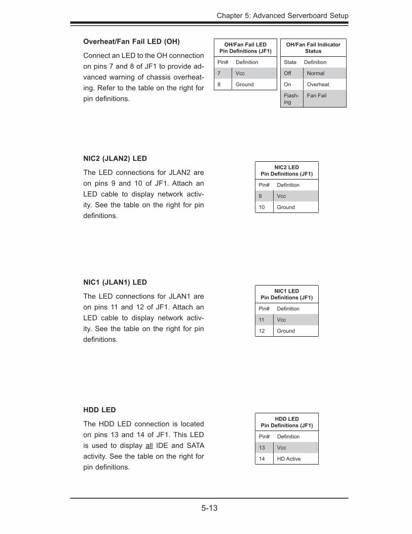
Overheat/Fan Fail LED (OH)
Connect an LED to the OH connection on pins 7 and 8 of JF1 to provide ad-vanced warning of chassis overheat-ing. Refer to the table on the right for pin defi nitions.
HDD LED
The HDD LED connection is located on pins 13 and 14 of JF1. This LED is used to display all IDE and SATA activity. See the table on the right for pin defi nitions.
OH/Fan Fail LEDPin Defi nitions (JF1)
Pin# Defi nition
7 Vcc
8 Ground
NIC2 LEDPin Defi nitions (JF1)
Pin# Defi nition
9 Vcc
10 Ground
HDD LEDPin Defi nitions (JF1)
Pin# Defi nition
13 Vcc
14 HD Active
NIC2 (JLAN2) LED
The LED connections for JLAN2 are on pins 9 and 10 of JF1. Attach an LED cable to display network activ-ity. See the table on the right for pin defi nitions.
NIC1 LEDPin Defi nitions (JF1)
Pin# Defi nition
11 Vcc
12 Ground
NIC1 (JLAN1) LED
The LED connections for JLAN1 are on pins 11 and 12 of JF1. Attach an LED cable to display network activ-ity. See the table on the right for pin defi nitions.
OH/Fan Fail Indicator Status
State Defi nition
Off Normal
On Overheat
Flash-ing
Fan Fail
5-14
SUPERSERVER 8015C-T User's Manual
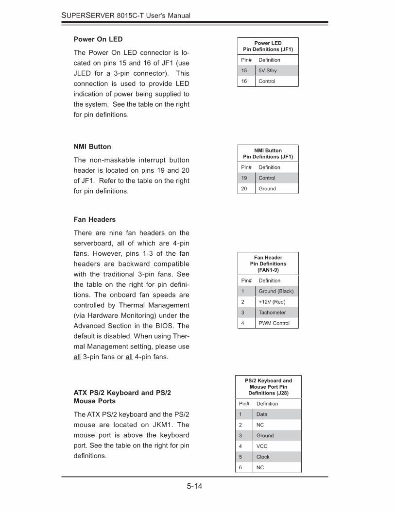
Fan Headers
There are nine fan headers on the serverboard, all of which are 4-pin fans. However, pins 1-3 of the fan headers are backward compatible with the traditional 3-pin fans. See the table on the right for pin defi ni-tions. The onboard fan speeds are controlled by Thermal Management (via Hardware Monitoring) under the Advanced Section in the BIOS. The default is disabled. When using Ther-mal Management setting, please use all 3-pin fans or all 4-pin fans.
ATX PS/2 Keyboard and PS/2 Mouse Ports
The ATX PS/2 keyboard and the PS/2 mouse are located on JKM1. The mouse port is above the keyboard port. See the table on the right for pin defi nitions.
NMI Button
The non-maskable interrupt button header is located on pins 19 and 20 of JF1. Refer to the table on the right for pin defi nitions.
NMI ButtonPin Defi nitions (JF1)
Pin# Defi nition
19 Control
20 Ground
Fan HeaderPin Defi nitions
(FAN1-9)
Pin# Defi nition
1 Ground (Black)
2 +12V (Red)
3 Tachometer
4 PWM Control
PS/2 Keyboard and Mouse Port Pin Defi nitions (J28)
Pin# Defi nition
1 Data
2 NC
3 Ground
4 VCC
5 Clock
6 NC
Power On LED
The Power On LED connector is lo-cated on pins 15 and 16 of JF1 (use JLED for a 3-pin connector). This connection is used to provide LED indication of power being supplied to the system. See the table on the right for pin defi nitions.
Power LEDPin Defi nitions (JF1)
Pin# Defi nition
15 5V Stby
16 Control
Chapter 5: Advanced Serverboard Setup
5-15
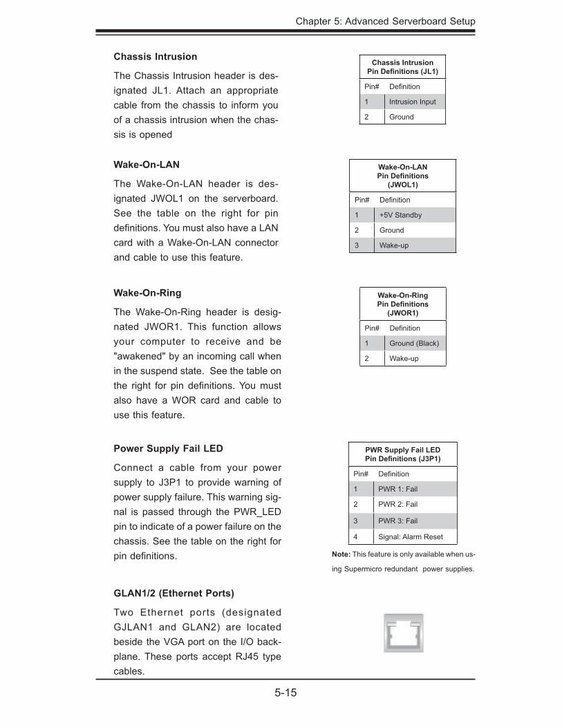
Wake-On-LAN
The Wake-On-LAN header is des-ignated JWOL1 on the serverboard. See the table on the right for pin defi nitions. You must also have a LAN card with a Wake-On-LAN connector and cable to use this feature.
Chassis Intrusion
The Chassis Intrusion header is des-ignated JL1. Attach an appropriate cable from the chassis to inform you of a chassis intrusion when the chas-sis is opened
Chassis IntrusionPin Defi nitions (JL1)
Pin# Defi nition
1 Intrusion Input
2 Ground
Wake-On-LANPin Defi nitions
(JWOL1)
Pin# Defi nition
1 +5V Standby
2 Ground
3 Wake-up
GLAN1/2 (Ethernet Ports)
Two Ethernet ports (designated GJLAN1 and GLAN2) are located beside the VGA port on the I/O back-plane. These ports accept RJ45 type cables.
Wake-On-Ring
The Wake-On-Ring header is desig-nated JWOR1. This function allows your computer to receive and be "awakened" by an incoming call when in the suspend state. See the table on the right for pin defi nitions. You must also have a WOR card and cable to use this feature.
Wake-On-RingPin Defi nitions
(JWOR1)
Pin# Defi nition
1 Ground (Black)
2 Wake-up
Power Supply Fail LED
Connect a cable from your power supply to J3P1 to provide warning of power supply failure. This warning sig-nal is passed through the PWR_LED pin to indicate of a power failure on the chassis. See the table on the right for pin defi nitions. Note: This feature is only available when us-
ing Supermicro redundant power supplies.
PWR Supply Fail LEDPin Defi nitions (J3P1)
Pin# Defi nition
1 PWR 1: Fail
2 PWR 2: Fail
3 PWR 3: Fail
4 Signal: Alarm Reset
5-16
SUPERSERVER 8015C-T User's Manual
Serial Ports
Two serial ports are included on the serverboard. COM1 is a backpanel port and COM2 is a header located near the onboard battery. See the table on the right for pin defi nitions.
Serial Port Pin Defi nitions(COM1/COM2)
Pin # Defi nition Pin # Defi nition
1 DCD 6 DSR
2 RXD 7 RTS
3 TXD 8 CTS
4 DTR 9 RI
5 Ground 10 NC
Universal Serial Bus (USB)
There are two Universal Serial Bus ports located on the I/O panel and three additional USB headers located on the serverboard. The headers can be used to provide front side USB access (cables not included). See the table on the right for pin defi nitions.
Universal Serial BusPin Defi nitions (USB)
USB0/1Pin # Defi nition
USB2/3/4Pin # Defi nition
1 +5V 1 +5V
2 PO- 2 PO-
3 PO+ 3 PO+
4 Ground 4 Ground
5 N/A 5 Key
Power LED/Speaker
On JD1 header, pins 1-3 are for a power LED and pins 4-7 are for the speaker. Close pins 4-7 with a jumper to use an external speaker. If you wish to use the onboard speaker, please close pins 6-7. See the table on the right for speaker pin defi nitions.
Power LED/Speaker Connector (JD1)
Pin Setting Defi nition
Pins 6-7 Internal Speaker
Pins 4-7 External Speaker
SGPIO Header
The SGPIO (Serial General Purpose Input/Output) headers are located at J15/J16. These headers are used to "talk to" a system-monitoring chip on the backplane. See the table on the right for pin defi nitions.
SGPIO HeaderPin Defi nitions (J15/J16)
Pin# Defi nition Pin Defi nition
1 *NC 2 *NC
3 Ground 4 DATA Out
5 Load 6 Ground
7 Clock 8 *NC
NC = No Connection
Chapter 5: Advanced Serverboard Setup
5-17
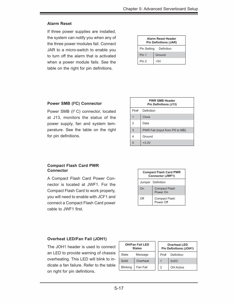
Power SMB (I2C) Connector
Power SMB (I2 C) connector, located at J13, monitors the status of the power supply, fan and system tem-perature. See the table on the right for pin defi nitions.
PWR SMB HeaderPin Defi nitions (J13)
Pin# Defi nition
1 Clock
2 Data
3 PWR Fail (Input from PS to MB)
4 Ground
5 +3.3V
Alarm Reset
If three power supplies are installed, the system can notify you when any of the three power modules fail. Connect JAR to a micro-switch to enable you to turn off the alarm that is activated when a power module fails. See the table on the right for pin defi nitions.
Alarm Reset HeaderPin Defi nitions (JAR)
Pin Setting Defi nition
Pin 1 Ground
Pin 2 +5V
Overheat LED/Fan Fail (JOH1)
The JOH1 header is used to connect an LED to provide warning of chassis overheating. This LED will blink to in-dicate a fan failure. Refer to the table on right for pin defi nitions.
Overheat LEDPin Defi nitions (JOH1)
Pin# Defi nition
1 5vDC
2 OH Active
OH/Fan Fail LED States
State Message
Solid Overheat
Blinking Fan Fail
Compact Flash Card PWR Connector
A Compact Flash Card Power Con-nector is located at JWF1. For the Compact Flash Card to work properly, you will need to enable with JCF1 and connect a Compact Flash Card power cable to JWF1 fi rst.
Compact Flash Card PWR Connector (JWF1)
Jumper Defi nition
On Compact Flash Power On
Off Compact Flash Power Off
5-18
SUPERSERVER 8015C-T User's Manual
5-10 Jumper Settings
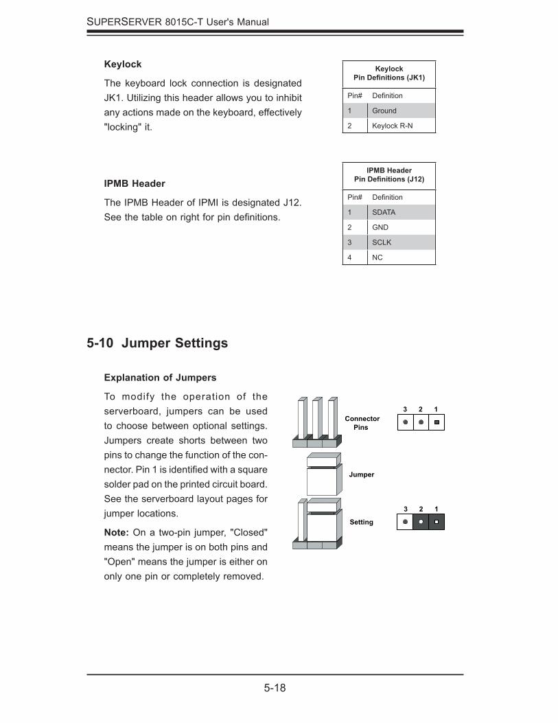
Explanation of Jumpers
To modify the operation of the serverboard, jumpers can be used to choose between optional settings. Jumpers create shorts between two pins to change the function of the con-nector. Pin 1 is identifi ed with a square solder pad on the printed circuit board. See the serverboard layout pages for jumper locations.
Note: On a two-pin jumper, "Closed" means the jumper is on both pins and "Open" means the jumper is either on only one pin or completely removed.
ConnectorPins
Jumper
Setting
3 2 1
3 2 1
Keylock
The keyboard lock connection is designated JK1. Utilizing this header allows you to inhibit any actions made on the keyboard, effectively "locking" it.
KeylockPin Defi nitions (JK1)
Pin# Defi nition
1 Ground
2 Keylock R-N
IPMB Header
The IPMB Header of IPMI is designated J12. See the table on right for pin defi nitions.
IPMB HeaderPin Defi nitions (J12)
Pin# Defi nition
1 SDATA
2 GND
3 SCLK
4 NC
Chapter 5: Advanced Serverboard Setup
5-19
CMOS Clear
JBT1 is used to clear CMOS (which will also clear any passwords). Instead of pins, this jumper consists of contact pads to prevent accidentally clearing the contents of CMOS.
To clear CMOS,
First power down the system and unplug the power cord(s).
With the power disconnected, short the CMOS pads with a metal object such as a small screwdriver.
Remove the screwdriver (or shorting device).
Reconnect the power cord(s) and power on the system.
Note: Do not use the PW_ON connector to clear CMOS.
1.
2.
3.
4.
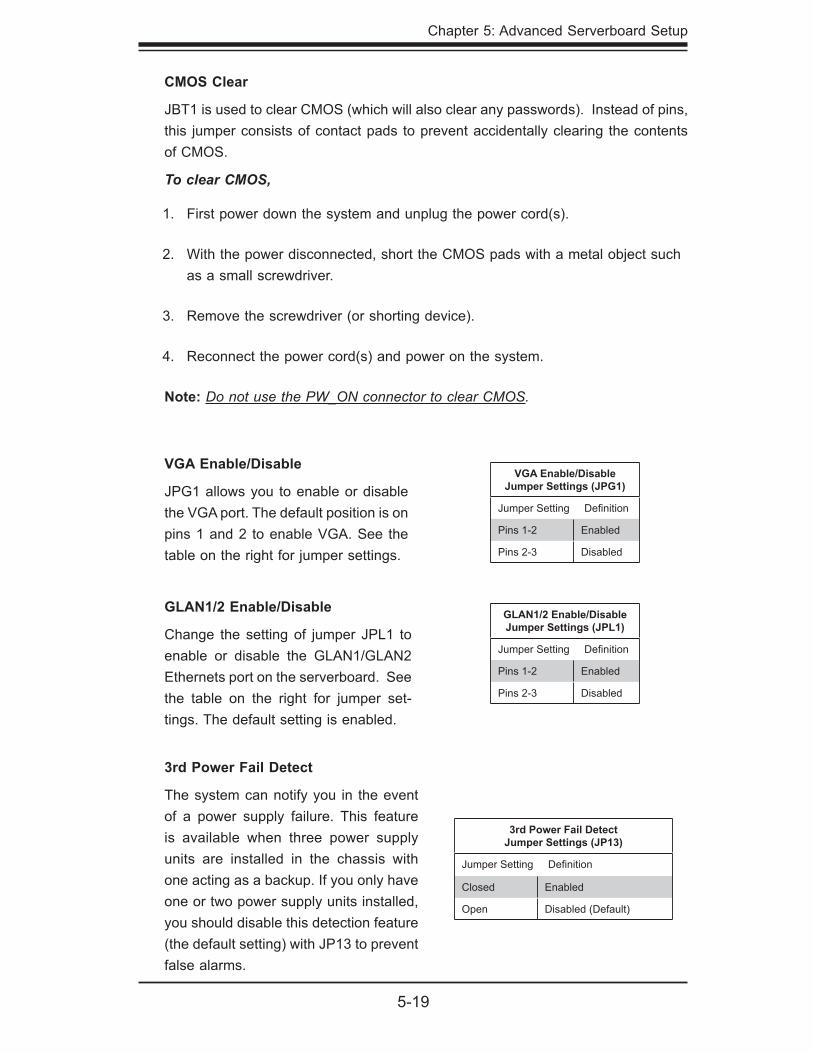
VGA Enable/Disable
JPG1 allows you to enable or disable the VGA port. The default position is on pins 1 and 2 to enable VGA. See the table on the right for jumper settings.
VGA Enable/Disable Jumper Settings (JPG1)
Jumper Setting Defi nition
Pins 1-2 Enabled
Pins 2-3 Disabled
3rd Power Fail Detect
The system can notify you in the event of a power supply failure. This feature is available when three power supply units are installed in the chassis with one acting as a backup. If you only have one or two power supply units installed, you should disable this detection feature (the default setting) with JP13 to prevent false alarms.
3rd Power Fail DetectJumper Settings (JP13)
Jumper Setting Defi nition
Closed Enabled
Open Disabled (Default)
GLAN1/2 Enable/Disable
Change the setting of jumper JPL1 to enable or disable the GLAN1/GLAN2 Ethernets port on the serverboard. See the table on the right for jumper set-tings. The default setting is enabled.
GLAN1/2 Enable/Disable Jumper Settings (JPL1)
Jumper Setting Defi nition
Pins 1-2 Enabled
Pins 2-3 Disabled
5-20
SUPERSERVER 8015C-T User's Manual
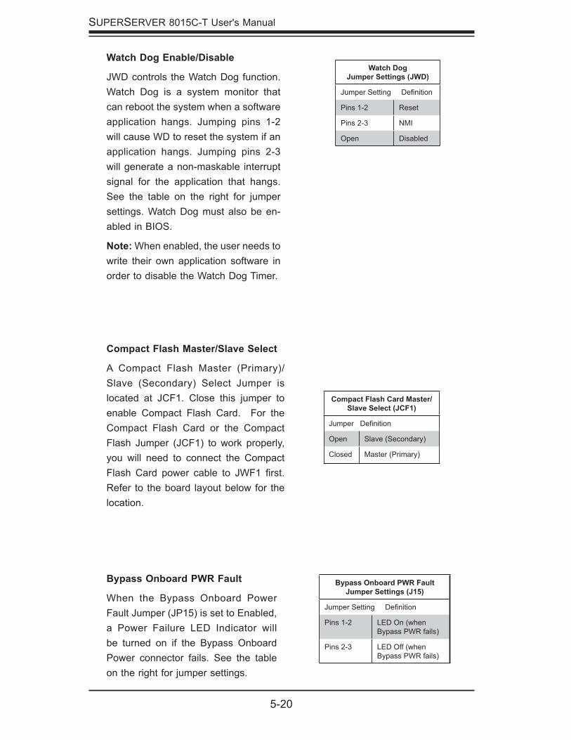
Compact Flash Master/Slave Select
A Compact Flash Master (Primary)/Slave (Secondary) Select Jumper is located at JCF1. Close this jumper to enable Compact Flash Card. For the Compact Flash Card or the Compact Flash Jumper (JCF1) to work properly, you will need to connect the Compact Flash Card power cable to JWF1 fi rst. Refer to the board layout below for the location.
Compact Flash Card Master/Slave Select (JCF1)
Jumper Defi nition
Open Slave (Secondary)
Closed Master (Primary)
Bypass Onboard PWR FaultJumper Settings (J15)
Jumper Setting Defi nition
Pins 1-2 LED On (when Bypass PWR fails)
Pins 2-3 LED Off (when Bypass PWR fails)
Bypass Onboard PWR Fault
When the Bypass Onboard Power Fault Jumper (JP15) is set to Enabled, a Power Failure LED Indicator will be turned on if the Bypass Onboard Power connector fails. See the table on the right for jumper settings.
Watch Dog Enable/Disable
JWD controls the Watch Dog function. Watch Dog is a system monitor that can reboot the system when a software application hangs. Jumping pins 1-2 will cause WD to reset the system if an application hangs. Jumping pins 2-3 will generate a non-maskable interrupt signal for the application that hangs. See the table on the right for jumper settings. Watch Dog must also be en-abled in BIOS.
Note: When enabled, the user needs to write their own application software in order to disable the Watch Dog Timer.
Watch Dog Jumper Settings (JWD)
Jumper Setting Defi nition
Pins 1-2 Reset
Pins 2-3 NMI
Open Disabled
Chapter 5: Advanced Serverboard Setup
5-21
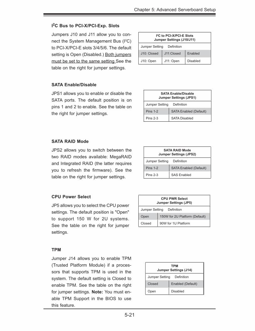
I2C to PCI-X/PCI-E SlotsJumper Settings (J10/J11)
Jumper Setting Defi nition
J10: Closed J11:Closed Enabled
J10: Open J11: Open Disabled
I2C Bus to PCI-X/PCI-Exp. Slots
Jumpers J10 and J11 allow you to con-nect the System Management Bus (I2C) to PCI-X/PCI-E slots 3/4/5/6. The default setting is Open (Disabled.) Both jumpers must be set to the same setting See the table on the right for jumper settings.
SATA Enable/DisableJumper Settings (JPS1)
Jumper Setting Defi nition
Pins 1-2 SATA Enabled (Default)
Pins 2-3 SATA Disabled
SATA Enable/Disable
JPS1 allows you to enable or disable the SATA ports. The default position is on pins 1 and 2 to enable. See the table on the right for jumper settings.
TPMJumper Settings (J14)
Jumper Setting Defi nition
Closed Enabled (Default)
Open Disabled
TPM
Jumper J14 allows you to enable TPM (Trusted Platform Module) if a proces-sors that supports TPM is used in the system. The default setting is Closed to enable TPM. See the table on the right for jumper settings. Note: You must en-able TPM Support in the BIOS to use this feature.
CPU PWR Select Jumper Settings (JP5)
Jumper Setting Defi nition
Open 150W for 2U Platform (Default)
Closed 90W for 1U Platform
CPU Power Select
JP5 allows you to select the CPU power settings. The default position is "Open" to support 150 W for 2U systems. See the table on the right for jumper settings.
SATA RAID ModeJumper Settings (JPS2)
Jumper Setting Defi nition
Pins 1-2 SATA Enabled (Default)
Pins 2-3 SAS Enabled
SATA RAID Mode
JPS2 allows you to switch between the two RAID modes available: MegaRAID and Integrated RAID (the latter requires you to refresh the fi rmware). See the table on the right for jumper settings.
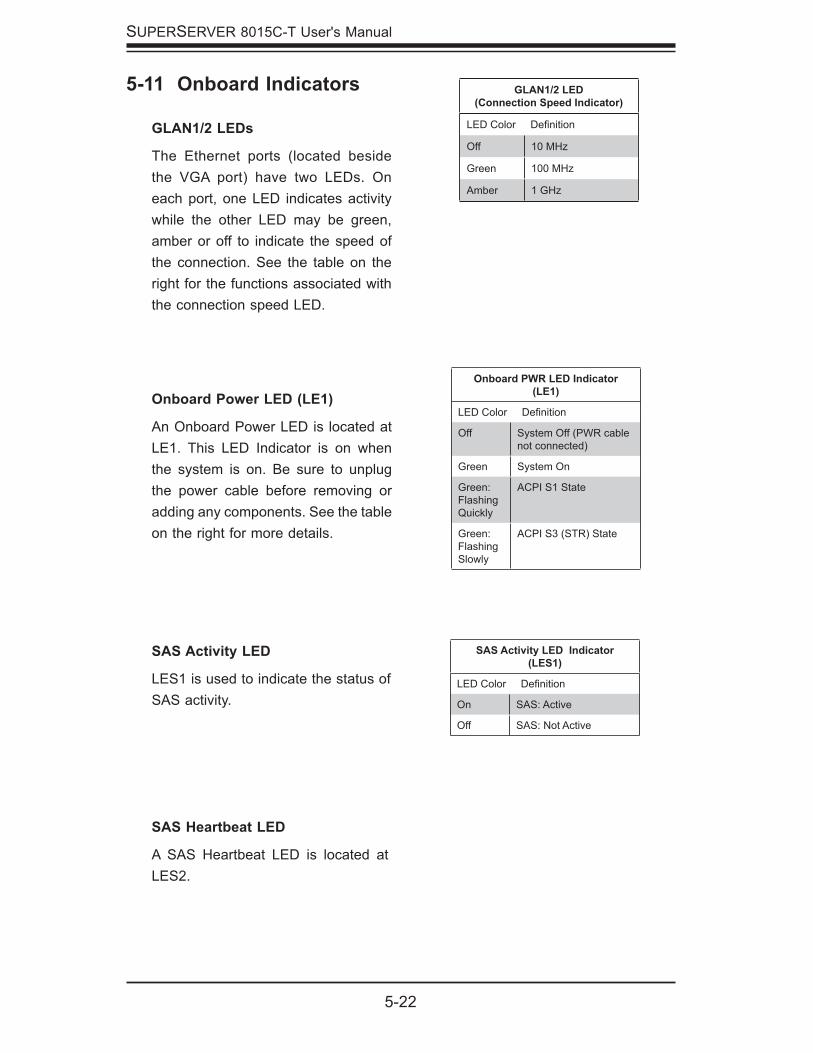
5-22
SUPERSERVER 8015C-T User's Manual
5-11 Onboard Indicators
GLAN1/2 LEDs
The Ethernet ports (located beside the VGA port) have two LEDs. On each port, one LED indicates activity while the other LED may be green, amber or off to indicate the speed of the connection. See the table on the right for the functions associated with the connection speed LED.
GLAN1/2 LED (Connection Speed Indicator)
LED Color Defi nition
Off 10 MHz
Green 100 MHz
Amber 1 GHz
Onboard Power LED (LE1)
An Onboard Power LED is located at LE1. This LED Indicator is on when the system is on. Be sure to unplug the power cable before removing or adding any components. See the table on the right for more details.
Onboard PWR LED Indicator(LE1)
LED Color Defi nition
Off System Off (PWR cable not connected)
Green System On
Green: Flashing Quickly
ACPI S1 State
Green: Flashing Slowly
ACPI S3 (STR) State
SAS Activity LED
LES1 is used to indicate the status of SAS activity.
SAS Activity LED Indicator(LES1)
LED Color Defi nition
On SAS: Active
Off SAS: Not Active
SAS Heartbeat LED
A SAS Heartbeat LED is located at LES2.
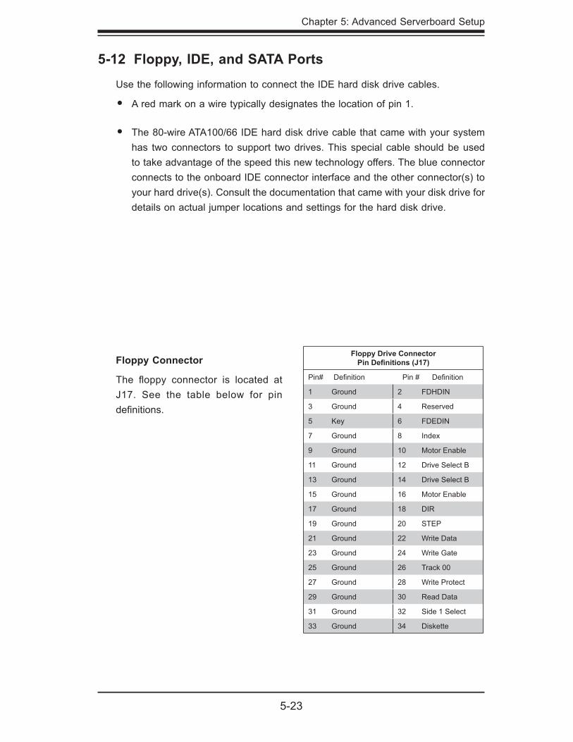
Chapter 5: Advanced Serverboard Setup
5-23
5-12 Floppy, IDE, and SATA Ports
Use the following information to connect the IDE hard disk drive cables.
A red mark on a wire typically designates the location of pin 1.
The 80-wire ATA100/66 IDE hard disk drive cable that came with your system has two connectors to support two drives. This special cable should be used to take advantage of the speed this new technology offers. The blue connector connects to the onboard IDE connector interface and the other connector(s) to your hard drive(s). Consult the documentation that came with your disk drive for details on actual jumper locations and settings for the hard disk drive.
•
•
Floppy Connector
The fl oppy connector is located at J17. See the table below for pin defi nitions.
Floppy Drive ConnectorPin Defi nitions (J17)
Pin# Defi nition Pin # Defi nition
1 Ground 2 FDHDIN
3 Ground 4 Reserved
5 Key 6 FDEDIN
7 Ground 8 Index
9 Ground 10 Motor Enable
11 Ground 12 Drive Select B
13 Ground 14 Drive Select B
15 Ground 16 Motor Enable
17 Ground 18 DIR
19 Ground 20 STEP
21 Ground 22 Write Data
23 Ground 24 Write Gate
25 Ground 26 Track 00
27 Ground 28 Write Protect
29 Ground 30 Read Data
31 Ground 32 Side 1 Select
33 Ground 34 Diskette
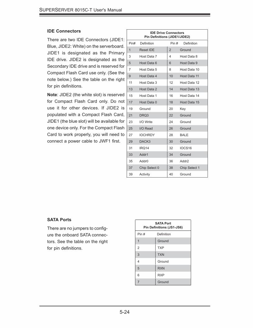
5-24
SUPERSERVER 8015C-T User's Manual
SATA Ports
There are no jumpers to confi g-ure the onboard SATA connec-tors. See the table on the right for pin defi nitions.
SATA PortPin Defi nitions (JS1-JS6)
Pin # Defi nition
1 Ground
2 TXP
3 TXN
4 Ground
5 RXN
6 RXP
7 Ground
IDE Drive ConnectorsPin Defi nitions (JIDE1/JIDE2)
Pin# Defi nition Pin # Defi nition
1 Reset IDE 2 Ground
3 Host Data 7 4 Host Data 8
5 Host Data 6 6 Host Data 9
7 Host Data 5 8 Host Data 10
9 Host Data 4 10 Host Data 11
11 Host Data 3 12 Host Data 12
13 Host Data 2 14 Host Data 13
15 Host Data 1 16 Host Data 14
17 Host Data 0 18 Host Data 15
19 Ground 20 Key
21 DRQ3 22 Ground
23 I/O Write 24 Ground
25 I/O Read 26 Ground
27 IOCHRDY 28 BALE
29 DACK3 30 Ground
31 IRQ14 32 IOCS16
33 Addr1 34 Ground
35 Addr0 36 Addr2
37 Chip Select 0 38 Chip Select 1
39 Activity 40 Ground
IDE Connectors
There are two IDE Connectors (JIDE1: Blue, JIDE2: White) on the serverboard. JIDE1 is designated as the Primary IDE drive. JIDE2 is designated as the Secondary IDE drive and is reserved for Compact Flash Card use only. (See the note below.) See the table on the right for pin defi nitions.
Note: JIDE2 (the white slot) is reserved for Compact Flash Card only. Do not use it for other devices. If JIDE2 is populated with a Compact Flash Card, JIDE1 (the blue slot) will be available for one device only. For the Compact Flash Card to work properly, you will need to connect a power cable to JWF1 fi rst.
Chapter 6: Advanced Chassis Setup
6-1
Chapter 6
Advanced Chassis Setup
This chapter covers the steps required to install components and perform mainte-nance on the SC818TQ-1000 chassis. For component installation, follow the steps in the order given to eliminate the most common problems encountered. If some steps are unnecessary, skip ahead to the next step.
Tools Required The only tool you will need to install components and perform maintenance is a Philips screwdriver.
6-1 Static-Sensitive Devices
Electrostatic discharge (ESD) can damage electronic com ponents. To prevent damage to any printed circuit boards (PCBs), it is important to handle them very carefully. The following measures are generally suffi cient to protect your equipment from ESD damage.
PrecautionsUse a grounded wrist strap designed to prevent static discharge.
Touch a grounded metal object before removing any board from its antistatic bag.
Handle a board by its edges only; do not touch its components, peripheral chips, memory modules or gold contacts.
When handling chips or modules, avoid touching their pins.
Put the serverboard, add-on cards and peripherals back into their antistatic bags when not in use.
For grounding purposes, make sure your computer chassis provides excellent conductivity between the power supply, the case, the mounting fasteners and the serverboard.
•
•
•
•
•
•
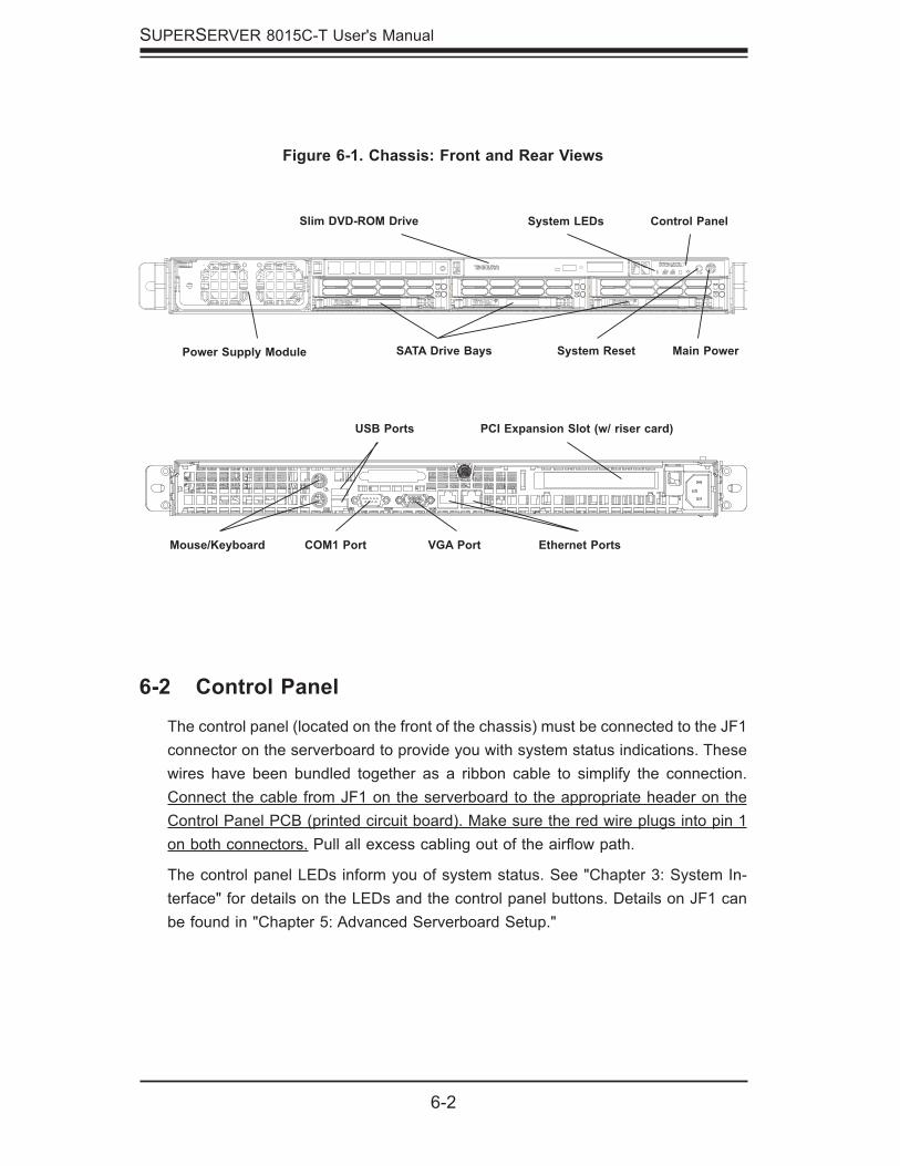
6-2
SUPERSERVER 8015C-T User's Manual
Figure 6-1. Chassis: Front and Rear Views
System Reset
6-2 Control Panel
The control panel (located on the front of the chassis) must be connected to the JF1 connector on the serverboard to provide you with system status indications. These wires have been bundled together as a ribbon cable to simplify the connection. Connect the cable from JF1 on the serverboard to the appropriate header on the Control Panel PCB (printed circuit board). Make sure the red wire plugs into pin 1 on both connectors. Pull all excess cabling out of the airfl ow path.
The control panel LEDs inform you of system status. See "Chapter 3: System In-terface" for details on the LEDs and the control panel buttons. Details on JF1 can be found in "Chapter 5: Advanced Serverboard Setup."
Control PanelSystem LEDs
Main Power SATA Drive BaysPower Supply Module
PCI Expansion Slot (w/ riser card)
Mouse/Keyboard
USB Ports
COM1 Port Ethernet PortsVGA Port
Slim DVD-ROM Drive
Chapter 6: Advanced Chassis Setup
6-3
6-3 System Fans
Six 4-cm heavy duty counter-rotating fans provide the cooling for the 8015C-T. Each fan unit is actually made up of two fans joined back-to-back, which rotate in opposite directions. This counter-rotating action generates exceptional airfl ow and works to dampen vibration levels. It is very important that the chassis top cover is properly installed and making a good seal in order for the cooling air to circulate properly through the chassis and cool the components. See Figure 6-2.
System Fan FailureFan speed is controlled by system temperature via a BIOS setting. If a fan fails, the remaining fan will ramp up to full speed and the overheat/fan fail LED on the control panel will turn on. Replace any failed fan at your earliest convenience with the same type and model (the system can continue to run with a failed fan). Remove the top chassis cover while the system is still running to determine which of the fans has failed. Then power down the system before replacing a fan. Removing the power cord(s) is also recommended as a safety precaution.
Replacing System Fans
Removing a fanAfter turning off the power to the system, fi rst remove the chassis cover and unplug the fan cable from the serverboard. Unscrew the failed blower fan from the chassis and pull it completely out from the serverboard.
Installing a new fanReplace the failed fan with an identical 4-cm, 12 volt fan (available from Supermicro: p/n FAN-0086L). Push the new fan into the vacant space in the housing while mak-ing sure the arrows on the top of the fan (indicating air direction) point in the same direction as the arrows on the other fans. Reposition the fan housing back over the two mounting posts in the chassis, then reconnect the fan wires to the same chassis fan headers you removed them from. Power up the system and check that the fan is working properly and that the LED on the control panel has turned off. Finish by replacing the chassis cover.
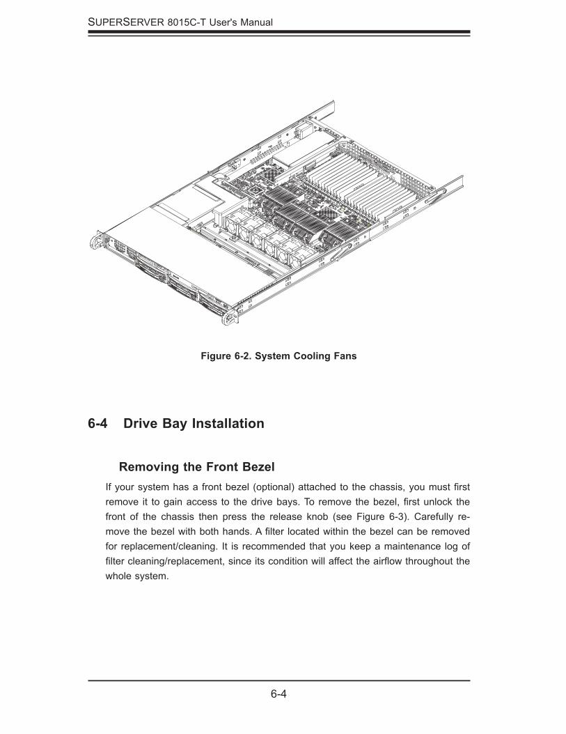
6-4
SUPERSERVER 8015C-T User's Manual
Figure 6-2. System Cooling Fans
6-4 Drive Bay Installation
Removing the Front BezelIf your system has a front bezel (optional) attached to the chassis, you must fi rst remove it to gain access to the drive bays. To remove the bezel, fi rst unlock the front of the chassis then press the release knob (see Figure 6-3). Carefully re-move the bezel with both hands. A fi lter located within the bezel can be removed for replacement/cleaning. It is recommended that you keep a maintenance log of fi lter cleaning/replacement, since its condition will affect the airfl ow throughout the whole system.
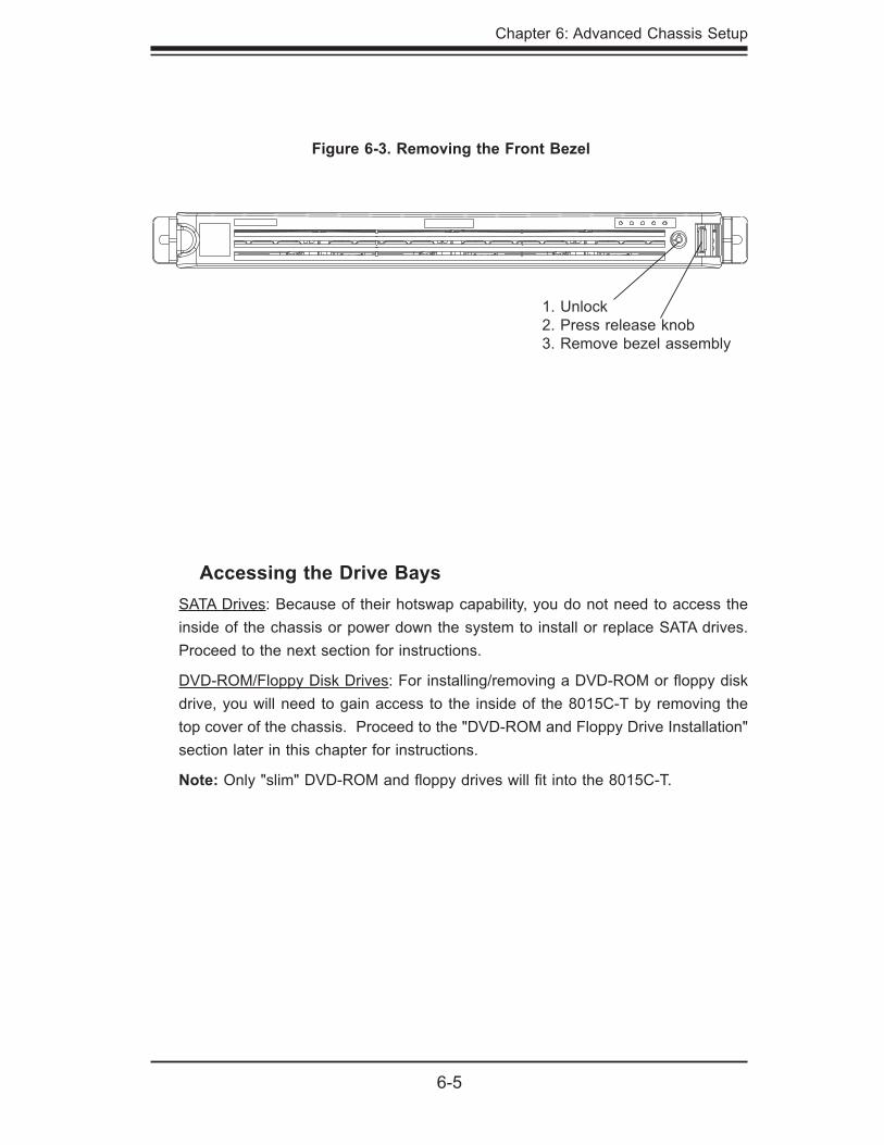
Chapter 6: Advanced Chassis Setup
6-5
Accessing the Drive BaysSATA Drives: Because of their hotswap capability, you do not need to access the inside of the chassis or power down the system to install or replace SATA drives. Proceed to the next section for instructions.
DVD-ROM/Floppy Disk Drives: For installing/removing a DVD-ROM or fl oppy disk drive, you will need to gain access to the inside of the 8015C-T by removing the top cover of the chassis. Proceed to the "DVD-ROM and Floppy Drive Installation" section later in this chapter for instructions.
Note: Only "slim" DVD-ROM and fl oppy drives will fi t into the 8015C-T.
Figure 6-3. Removing the Front Bezel
1. Unlock2. Press release knob3. Remove bezel assembly
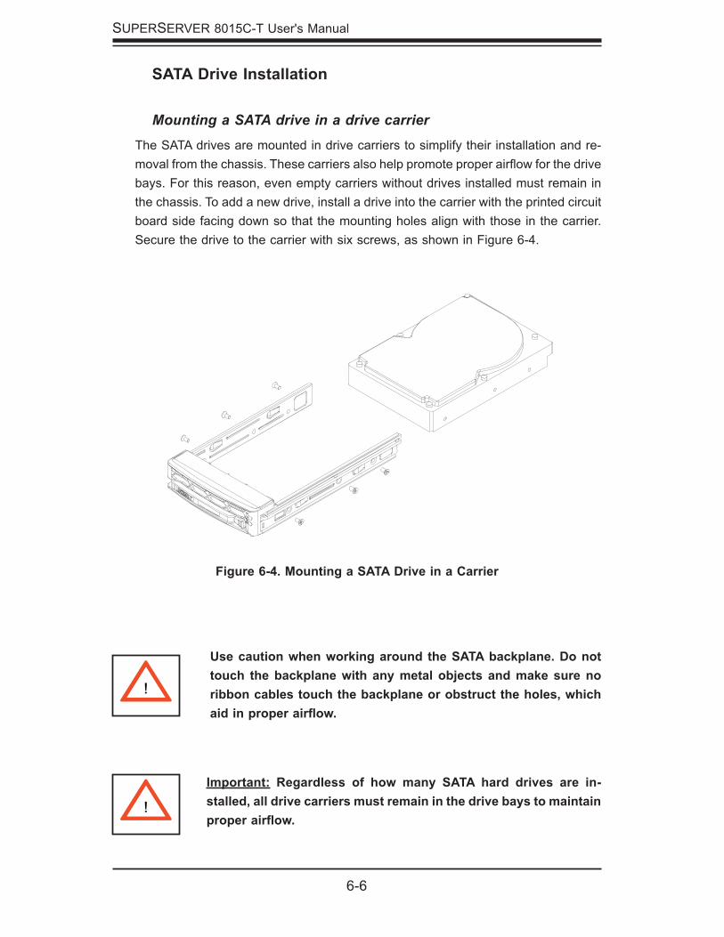
6-6
SUPERSERVER 8015C-T User's Manual
Figure 6-4. Mounting a SATA Drive in a Carrier
!
Important: Regardless of how many SATA hard drives are in-stalled, all drive carriers must remain in the drive bays to maintain proper airfl ow.
Use caution when working around the SATA backplane. Do not touch the backplane with any metal objects and make sure no ribbon cables touch the backplane or obstruct the holes, which aid in proper airfl ow.
!
SATA Drive Installation
Mounting a SATA drive in a drive carrierThe SATA drives are mounted in drive carriers to simplify their installation and re-moval from the chassis. These carriers also help promote proper airfl ow for the drive bays. For this reason, even empty carriers without drives installed must remain in the chassis. To add a new drive, install a drive into the carrier with the printed circuit board side facing down so that the mounting holes align with those in the carrier. Secure the drive to the carrier with six screws, as shown in Figure 6-4.
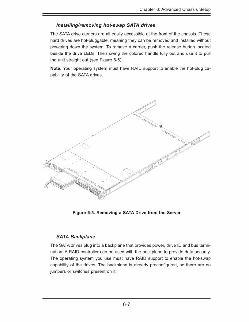
Chapter 6: Advanced Chassis Setup
6-7
Figure 6-5. Removing a SATA Drive from the Server
SATA BackplaneThe SATA drives plug into a backplane that provides power, drive ID and bus termi-nation. A RAID controller can be used with the backplane to provide data security. The operating system you use must have RAID support to enable the hot-swap capability of the drives. The backplane is already preconfi gured, so there are no jumpers or switches present on it.
Installing/removing hot-swap SATA drivesThe SATA drive carriers are all easily accessible at the front of the chassis. These hard drives are hot-pluggable, meaning they can be removed and installed without powering down the system. To remove a carrier, push the release button located beside the drive LEDs. Then swing the colored handle fully out and use it to pull the unit straight out (see Figure 6-5).
Note: Your operating system must have RAID support to enable the hot-plug ca-pability of the SATA drives.
6-8
SUPERSERVER 8015C-T User's Manual
DVD-ROM and Floppy Drive InstallationThe top cover of the chassis must be opened to gain full access to the DVD-ROM and fl oppy drive bays. The 8015C-T accomodates only slim-line DVD-ROM drives. Side mounting brackets are needed to mount a slim-line DVD-ROM drive in the 8015C-T server.
You must power down the system before installing or removing a fl oppy or DVD-ROM drive. First, grasp the two handles on either side and pull the unit straight out until it locks (you will hear a "click"). Next, release the thumbscrew at the rear of the top chassis cover. Then depress the two buttons on the top of the chassis and at the same time, push the cover away from you until it stops. You can then lift the top cover from the chassis to gain full access to the inside of the server.
With the chassis cover removed, unplug the power and data cables from the drive you want to remove. Then locate the locking tab at the rear of the drive. It will be on the left side of the drive when viewed from the front of the chassis. Pull the tab away from the drive and push the drive unit out the front of the chassis. Add a new drive by following this procedure in reverse order. You may hear a faint *click* of the locking tab when the drive is fully inserted. Remember to reconnect the data and power cables to the drive before replacing the chassis cover and restoring power to the system. Please be aware of the following:
The fl oppy disk drive cable has seven twisted wires.
A color mark on a cable typically designates the location of pin 1.
A single fl oppy disk drive ribbon cable has 34 wires and two connectors to provide for two fl oppy disk drives. The connector with twisted wires always connects to drive A, and the connector that does not have twisted wires always connects to drive B.
•
•
•

Chapter 6: Advanced Chassis Setup
6-9
6-5 Power Supply
The SuperServer 8015C-T has a single 1000 watt power supply, which is auto-switching capable. This enables it to automatically sense and operate at a 100v to 240v input voltage. An amber light will be illuminated on the power supply when the power is off. An illuminated green light indicates that the power supply is op-erating.
Power Supply FailureIf the power supply unit fails, the system will shut down and you will need to replace the unit. Replacement units can be ordered directly from Supermicro (see contact information in the Preface). As there is only one power supply unit in the 8015C-T, power must be completely removed from the server before removing and replacing the power supply unit for whatever reason.
Removing the Power SupplyFirst unplug the power cord from the failed power supply module. The power supply module is cold-swappable. To remove the failed power module, simply push the release tab (on the back of the power supply) to the side and then pull the module straight out (see Figure 6-6). The power supply wiring was designed to detach automatically when the module is pulled from the chassis.
Installing a new Power SupplyReplace the failed power module with another PWS-1K01-1R power supply module. Push the new power supply module into the power bay until you hear a click. Finish by plugging the AC power cord back into the module and powering up the system by depressing the power on/off button.
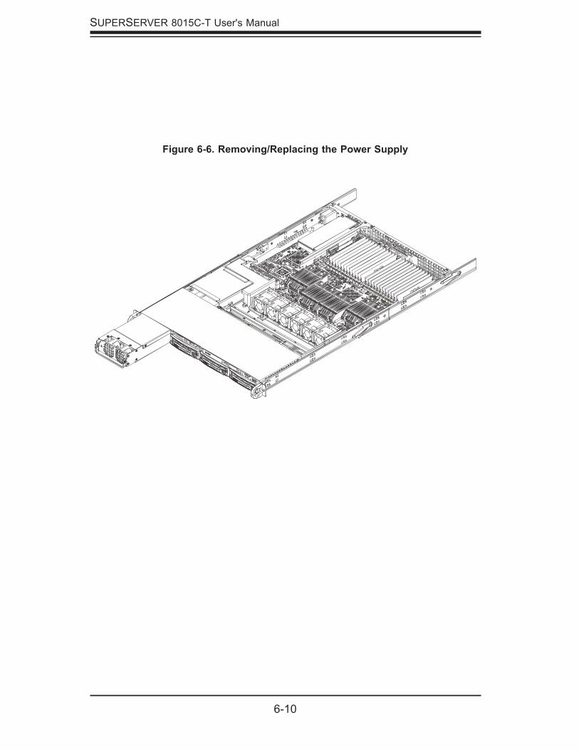
6-10
SUPERSERVER 8015C-T User's Manual
Figure 6-6. Removing/Replacing the Power Supply
Chapter 7: BIOS
7-1
Chapter 7
BIOS
7-1 Introduction
This chapter describes the AMIBIOS Setup Utility for the X7QCE. The AMI ROM BIOS is stored in a Flash EEPROM and can be easily updated using a fl oppy disk-based program.
Starting BIOS Setup UtilityTo enter the AMIBIOS Setup Utility screens, hit the <Delete> key while the system is booting up.
Note: In most cases, the <Delete> key is used to invoke the AMIBIOS setup screen. There are a few cases when other keys are used, such as <F1>, <F2>, etc.
The Main BIOS setup menu screen has two main frames. The left frame displays all the options that can be confi gured. “Grayed-out” options cannot be confi gured. Options in blue can be confi gured by the user. The right frame displays the key legend. Above the key legend is an area reserved for a text message. When an op-tion is selected in the left frame, it is highlighted in white. Often a text message will accompany it. (Note: the AMI BIOS has default text messages built in. Supermicro retains the option to include, omit, or change any of these text messages.)
The AMIBIOS Setup Utility uses a key-based navigation system called hot keys. Most of the AMIBIOS setup utility hot keys can be used at any time during the setup navigation process. These keys include <F1>, <F10>, <Enter>, <ESC>, arrow keys, etc. Options printed in Bold are default settings.)
The confi guration data that determines the system parameters may be changed by entering the AMI BIOS Setup utility (accessed by pressing <Del> during sys-tem boot.
Warning!! Do not shut down or reset the system while updating the BIOS to prevent possible boot failure.!
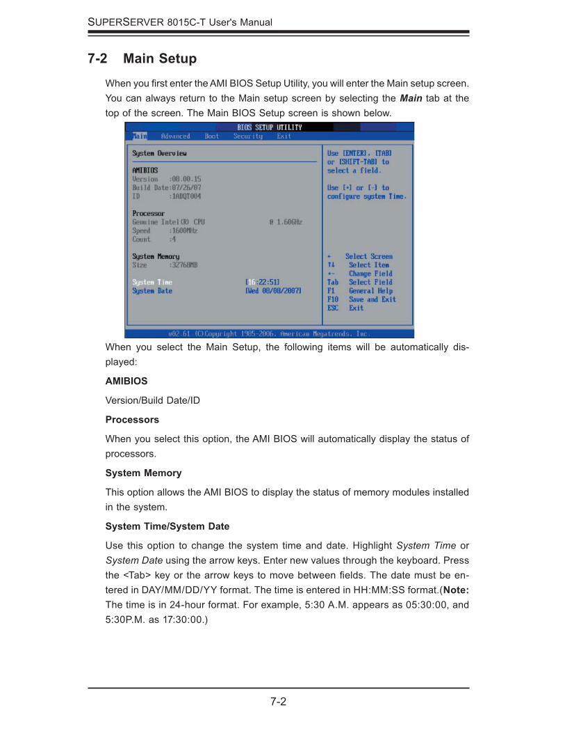
7-2
SUPERSERVER 8015C-T User's Manual
7-2 Main Setup
When you fi rst enter the AMI BIOS Setup Utility, you will enter the Main setup screen. You can always return to the Main setup screen by selecting the Main tab at the top of the screen. The Main BIOS Setup screen is shown below.
When you select the Main Setup, the following items will be automatically dis-played:
AMIBIOS
Version/Build Date/ID
Processors
When you select this option, the AMI BIOS will automatically display the status of processors.
System Memory
This option allows the AMI BIOS to display the status of memory modules installed in the system.
System Time/System Date
Use this option to change the system time and date. Highlight System Time or System Date using the arrow keys. Enter new values through the keyboard. Press the <Tab> key or the arrow keys to move between fi elds. The date must be en-tered in DAY/MM/DD/YY format. The time is entered in HH:MM:SS format.(Note: The time is in 24-hour format. For example, 5:30 A.M. appears as 05:30:00, and 5:30P.M. as 17:30:00.)
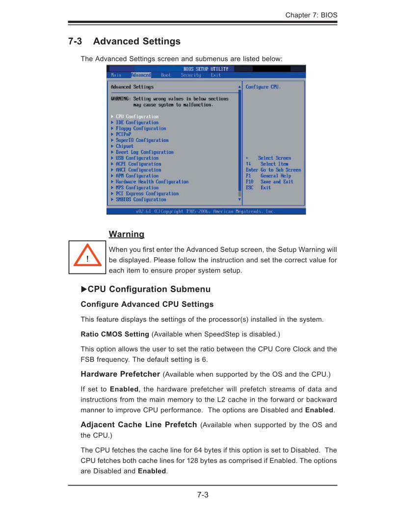
Chapter 7: BIOS
7-3
7-3 Advanced Settings
The Advanced Settings screen and submenus are listed below:
WarningWhen you fi rst enter the Advanced Setup screen, the Setup Warning will be displayed. Please follow the instruction and set the correct value for each item to ensure proper system setup.
�CPU Confi guration SubmenuConfi gure Advanced CPU Settings
This feature displays the settings of the processor(s) installed in the system.
Ratio CMOS Setting (Available when SpeedStep is disabled.)
This option allows the user to set the ratio between the CPU Core Clock and the FSB frequency. The default setting is 6.
Hardware Prefetcher (Available when supported by the OS and the CPU.)
If set to Enabled, the hardware prefetcher will prefetch streams of data and instructions from the main memory to the L2 cache in the forward or backward manner to improve CPU performance. The options are Disabled and Enabled.
Adjacent Cache Line Prefetch (Available when supported by the OS and the CPU.)
The CPU fetches the cache line for 64 bytes if this option is set to Disabled. The CPU fetches both cache lines for 128 bytes as comprised if Enabled. The options are Disabled and Enabled.
!
7-4
SUPERSERVER 8015C-T User's Manual
Intel Virtualization Technology (Available when supported by the OS and the CPU.)
Select Enabled to use the feature of Virtualization Technology to allow one platform to run multiple operating systems and applications in independent partitions, creating multiple "virtual" systems in one physical computer. The options are Enabled and Disabled. Note: If there is any change to this setting, you will need to power off and restart the system for the change to take effect. Please refer to Intel’s web site for detailed information.
Execute-Disable Bit Capability (Available when supported by the OS and the CPU.)
Set to Enabled to enable the Execute Disable Bit feature to allow the processor to classify areas in the system memory where an application code can execute and where it cannot, thus preventing a worm or a virus from creating a fl ood of codes to overwhelm the processor or damage the system during an attack. Note: For more information regarding hardware/software support for this function, please refer to Intel's and Microsoft's web sites.
Intel SpeedStep Technology (Available when supported by the CPU.)
The Enhanced Intel SpeedStep Technology allows the system to automatically adjust processor voltage and core frequency in an effort to reduce power consumption and heat dissipation. Select Maximum to set the CPU speed to the maximum. Select Minimum to set the CPU speed to the minimum. Select Auto to allow the CPU speed to be controlled by the OS. Select Disabled to disable this feature. (Refer to Intel’s web site for detailed information.)
�IDE Confi guration SubmenuWhen this Submenu is selected, the AMI BIOS automatically displays the follow-ing items:
ATA/IDE Confi guration
This feature allows the user to confi gure the ATA/IDE mode. The options are Disabled, Compatible, and Enhanced.
Confi gure SATA As
This feature allows the user to confi gure the onboard SATA slots as IDE Drives, RAID Drives, or AHCI Drives. The options are IDE, RAID, and AHCI.
Chapter 7: BIOS
7-5
Type
This feature allows the user to select the type of device connected to the system. The options are Not Installed, Auto, CDROM, and ARMD.
LBA/Large Mode
Logical Block Addressing (LBA) is a method of addressing data on a disk drive. In the LBA mode, the maximum drive capacity is 137 GB. For drive capacities over 137 GB, your system must be equipped with a 48-bit LBA mode address-ing. If not, contact your manufacturer or install an ATA/133 IDE controller card that supports 48-bit LBA mode. The options are Disabled and Auto.
Block (Multi-Sector Transfer)
This feature allows the user to use the Block Mode to boost the IDE drive per-formance by increasing the amount of data transferred. Only 512 bytes of data can be transferred per interrupt if the Block Mode is not used. If the Block Mode is used, data will be transferred of up to 64 KB per interrupt. If set to Disabled, data will be transferred from and to the device one sector at a time. If set to Auto, data will be transferred from and to the device multiple sectors at a time if the device supports it. The options are Auto and Disabled.
PIO Mode
The IDE PIO (Programmable I/O) Mode programs timing cycles between the IDE drive and the programmable IDE controller. As the PIO mode increases, the cycle time decreases. The options are Auto, 0, 1, 2, 3, and 4. Select Auto to allow the AMI BIOS to automatically detect the PIO mode. Use this value if the IDE disk drive support cannot be determined. Select 0 to allow the AMI BIOS to use PIO mode 0. It has a data transfer rate of 3.3 MBs. Select 1 to allow the AMI BIOS to use PIO mode 1. It has a data transfer rate of 5.2 MBs. Select 2 to allow the AMI BIOS to use PIO mode 2. It has a data transfer rate of 8.3 MBs. Select 3 to allow the AMI BIOS to use PIO mode 3. It has a data transfer rate of 11.1 MBs. Select 4 to allow the AMI BIOS to use PIO mode 4. It has a data transfer rate of 16.6 MBs. This setting generally works with all hard disk drives manufactured after 1999. For other disk drives, such as IDE CD-ROM drives, check the specifi cations of the drive.
Primary IDE Channel Master/Slave, Secondary IDE Channel Master/Slave
These settings allow the user to set the parameters of Primary IDE Channel Master/Slave and Secondary IDE Channel Master/Slave slots. Hit <Enter> to activate the following Submenu screen for detailed options of these items. Set the correct confi gurations accordingly. The items included in the Submenu are the following:
7-6
SUPERSERVER 8015C-T User's Manual
DMA Mode
Select Auto to allow the BIOS to automatically detect the DMA mode. Use this value if the IDE disk drive support cannot be determined. Select SWDMA0 to allow the BIOS to use Single Word DMA mode 0. It has a data transfer rate of 2.1 MBs. Select SWDMA1 to allow the BIOS to use Single Word DMA mode 1. It has a data transfer rate of 4.2 MBs. Select SWDMA2 to allow the BIOS to use Single Word DMA mode 2. It has a data transfer rate of 8.3 MBs. Select MWDMA0 to allow the BIOS to use Multi Word DMA mode 0. It has a data transfer rate of 4.2 MBs. Select MWDMA1 to allow the BIOS to use Multi Word DMA mode 1. It has a data transfer rate of 13.3 MBs. Select MWDMA2 to al-low the BIOS to use Multi-Word DMA mode 2. It has a data transfer rate of 16.6 MBs. Select UDMA0 to allow the BIOS to use Ultra DMA mode 0. It has a data transfer rate of 16.6 MBs. It has the same transfer rate as PIO mode 4 and Multi Word DMA mode 2. Select UDMA1 to allow the BIOS to use Ultra DMA mode 1. It has a data transfer rate of 25 MBs. Select UDMA2 to allow the BIOS to use Ultra DMA mode 2. It has a data transfer rate of 33.3 MBs. Select UDMA3 to allow the BIOS to use Ultra DMA mode 3. It has a data transfer rate of 66.6 MBs. Select UDMA4 to allow the BIOS to use Ultra DMA mode 4 . It has a data transfer rate of 100 MBs. The options are Auto, SWDMAn, MWDMAn, and UDMAn.
S.M.A.R.T. For Hard disk drives
Self-Monitoring Analysis and Reporting Technology (SMART) can help predict impending drive failures. Select Auto to allow the AMI BIOS to automatically detect hard disk drive support. The options are Disabled, Enabled, and Auto.
32-Bit Data Transfer
Select Enabled to use the feature of 32-Bit data transfer. Select "Disabled" to disable this function. The options are Enabled and Disabled.
Hard Disk Write Protect
Select Enabled to use the feature of Hard Disk Write Protect to prevent data from being written to HDD. The options are Enabled or Disabled.
IDE Detect Time Out
This feature allows the user to set the system time-out value to allow the BIOS to detect the ATA, ATAPI devices installed in the system. The options are 0 (sec), 5, Mode 1.0, 15, 20, 25, 30, and 35.
ATA(PI) 80Pin Cable Detection
This feature allows the AMI BIOS to automatically detect 80Pin ATA(PI) Cable. The options are Host & Device, Host, and Device.
Chapter 7: BIOS
7-7
�Floppy Confi guration This option allows the user to confi gure the settings for the Floppy Drives installed in the system.
Floppy A/Floppy B
Move the cursor to these fi elds via the up and down arrow keys to select the fl oppy type. The options are Disabled, 360 KB 5 1/4", 1.2 MB 5 1/4", 720 KB 3½", 1.44 MB 3½”, and 2.88 MB 3½".
�PCI/PnP Confi guration This feature allows the user to set the PCI/PnP confi gurations for the following items:
Clear NVRAM
Select Yes to clear NVRAM during system boot. The options are Yes and No.
Plug & Play OS
Select Yes to allow the OS to confi gure Plug & Play devices. (This is not required for system boot if your system has an OS that supports Plug & Play.) Select No to allow the AMI BIOS to confi gure all devices in the system.
PCI Latency Timer
This feature sets the latency Timer of each PCI device installed on a PCI bus. The default setting is 64. Select 32 to set the PCI latency to 32 PCI clock cycles. Select 64 to set the PCI latency to 64 PCI clock cycles. Select 96 to set the PCI latency to 96 PCI clock cycles. Select 128 to set the PCI latency to 128 PCI clock cycles. Select 160 to set the PCI latency to 160 PCI clock cycles. Select 192 to set the PCI latency to 192 PCI clock cycles. Select 224 to set the PCI latency to 224 PCI clock cycles. Select 248 to set the PCI latency to 248 PCI clock cycles.
Allocate IRQ to PCI VGA
Select Yes to allow the system to give the VGA adapter card an interrupt address. The options are Yes and No.
Palette Snooping
Select Enabled to inform the onboard PCI devices that an ISA graphics device is installed in the system in order for the graphics card to function properly. The options are Enabled and Disabled.
PCI IDE BusMaster
Select Enabled to allow the BIOS to use the PCI busmaster to read from and write to the onboard IDE drives. The options are Disabled and Enabled.
7-8
SUPERSERVER 8015C-T User's Manual
Offboard PCI/ISA IDE Card
This option allows the user to assign a PCI slot number to an off-board PCI/ISA IDE card in order for it to function properly. The options are Auto, PCI Slot1, PCI Slot2, PCI Slot3, PCI Slot4, PCI Slot5, and PCI Slot6.
IRQ3/IRQ4/IRQ5/IRQ7/IRQ9/IRQ10/IRQ11/IRQ14/IRQ15
This feature specifi es the availability of an IRQ to be used by a PCI, PnP device. Select Reserved for an IRQ to be used by a Legacy ISA device. The options are Available and Reserved.
DMA Channels 0~7
Select Available to indicate that a specifi c DMA channel is available to be used by a PCI/PnP device. Select Reserved if a DMA channel specifi ed is reserved for a Legacy ISA device.
Reserved Memory Size
This feature specifi es the size of memory block to be reserved for Legacy ISA devices. The options are Disabled, 16K, 32K, 64K.
�Super IO Confi guration SubmenuOnboard Floppy Controller
Select Enabled to enable the onboard fl oppy controller. The options are Enabled and Disabled.
Serial Port1 Address/Serial Port2 Address
This option specifi es the base I/O port addresses and the Interrupt Request ad-dresses for Serial Port 1 and Serial Port 2. Select Disabled to prevent the serial port from accessing any system resources. When set to Disabled, the serial port physically becomes unavailable. Select 3F8/IRQ4 to allow the serial port to use 3F8 as its I/O port address and IRQ 4 for the interrupt address. The options for Serial Port 1 are Disabled, 3F8/IRQ4, 3E8/IRQ4, and 2E8/IRQ3. The options for Serial Port 2 are Disabled, 2F8/IRQ3, 3E8/IRQ4 and 2E8/IRQ3.
Serial Port2 Mode
This option allows the user to confi gure the Serial Port2 Mode. The Options are Normal, Sharp IR, SIR, and Consumer (-Confi gured).
�Advanced Chipset Settings This item allows the user to confi gure the Advanced Chipset settings for the system.
Chapter 7: BIOS
7-9
�NorthBridge Confi guration
This feature allows the user to confi gure the NorthBridge Chipset settings.
Crystal Beach/DMA
This feature uses the Intel I/O AT (Acceleration Technology) to accelerate the performance of TOE devices. Note: A TOE device is a specialized, dedicated processor that is installed on an add-on card or a network card to handle some or all packet processing of this add-on card. For this motherboard, the TOE device is built inside the ESB 2 South Bridge chip. The options are Enabled and Disabled.
MCH (Memory Controller Hub) Branch Mode
This feature allows the user to decide how the two memory branches operate. System address space can either be interleaved between the two branches or sequencing from one branch to another. Mirror mode allows data correction by maintaining two copies of data in two branches. Single Channel 0 allows a single DIMM population during system manufacturing. The options are Interleave, Sequencing, Mirroring, and Single Channel 0.
Patrol Scrubbing
Scrubbing is a process that allows the northbridge to correct correctable memory errors found on FBD memory modules. Select Enabled to use Patrol Scrubbing, a background ECC memory correction activity initiated by the northbridge to fi nd and correct memory errors by scanning all memory modules doing simulated "READs" while checking for ECC errors. When an ECC error is detected during this process, it is logged as a Patrol error. A correctable error is corrected and written back into memory. The options are Enabled and Disabled.
Demand Scrubbing
Scrubbing is a process that allows the northbridge to correct correctable memory errors found on an FBD memory module. When the CPU or I/O issues a demand- read command, and the read data from memory turns out to be a correctable ECC, it is corrected and sent to the original source. Memory is updated as well. Select Enabled to use Demand Scrubbing for ECC memory correction. The options are Enabled and Disabled.
Branch 0 Rank Sparing/Branch 1 Rank Sparing
Select Enable to enable the sparing feature for Branch 0 or Branch 1 of the memory bus. The options are Enabled and Disabled.
Branch 0 Rank Interleaving/Branch 1 Rank Interleaving
Select Enable to enable the functions of Memory Interleaving for Branch 0 Rank or Branch 1 Rank. The options for Memory Interleaving are 1:1, 2:1 and 4:1.
7-10
SUPERSERVER 8015C-T User's Manual
FBD Thermal Throttle Mode
Select Enabled to use the feature of closed-loop thermal throttling on a fully buffered (FBD) memory module. If Enabled, thermal throttling will be activated when the temperature of an FBD module reaches a predefi ned threshold. The default setting is Enabled.
Clock Spectrum Feature
If Enabled, the BIOS will monitor the level of Electromagnetic Interference caused by the components and will attempt to decrease the interference whenever needed. The options are Enabled and Disabled.
Force ITK Confi guration Clocking
Select Enabled to confi gure FBD memory for ITK testing. The options are Enabled and Disabled.
ITK Branch
Select an ITK Branch to be excluded from the BNB Memory Map. When set to 0, all memory modules installed on Branch 1 must support Lockstep Operation. The options are 0 and 1.
Boot Graphics Adapter Priority
This feature allows the user to decide which graphics controller to be used as the primary boot device. The options are Auto and Onboard VGA.
Read Completion Coalescing
This feature allows you to enable the PCI-Express Compliance Mode. The options are Auto, Disabled and Enabled.
Non-Compliance Mode
Select the Compliance Mode to enable the PCI-Express Compliance Mode.The options are Non-Compliance and Compliance.
�SouthBridge Confi guration
This feature allows the user to confi gure the Intel ICH South Bridge settings.
SMBus Controller
Select Enabled to activate the onboard SMBus (System Management Bus) controller. The options are Enabled and Disabled.
USB Functions
This feature allows the user to decide the number of onboard USB ports to be enabled. The Options are: Disabled, 2 USB ports, 4 USB ports, and 6 USB ports.
Chapter 7: BIOS
7-11
USB2 Controller
Select Enabled to activate the onboard USB2 controller. The options are Enabled and Disabled.
SLP_S4# Minimum Assertion Width
This setting allows the user to select a desired length of time to be used as the SLP_S4# Min. Assertion Width. The options are 4-5 Sec., 3-4 Sec., 2-3 Sec. and 1-2 Sec.
Restore on AC Power Loss
This setting allows you to decide how the system will react when power returns after an unexpected power loss. The options are Stay Off, Power On and Last State.
PCI-E Port Confi gurationSlot#6 PCI-E x8
Select Auto to allow the BIOS to automatically confi gure PCI-E Slot#6 settings. The options are Disabled and Auto.
�ESB2 PCI-X Hub Confi guration
PCI Bus Frequency
This option allows the user to set the maximum PCI speed for the PCI slot specifi ed. Select Auto to allow the BIOS to automatically detect the capability of the device installed on the bus. The options for Slot 1 are Auto, 33 MHz PCI, 66 MHz PCI, 66 MHz PCI-X, 100 MHz PCI-X, and 133 MHz PCI-X. The options for Slot 2 are Auto, 66 MHz PCI, 100 MHz PCI-X, and 133 MHz PCI-X.
I/O Port Decode
This option allows the user to select the decode range for the I/O connections. The options are 4K Decode and 1K Decode.
RAS Sticky Error Handling
This option allows the user to decide how to handle Sticky RAS errors. The options are Clear Errors and Leave Errors (unchanged).
VGA 16-Bit Decode
Select Enabled to enable the function of decoding VGA for the devices installed behind the PXH PCI Controller Hub. The options are Enabled and Disabled.
IDTCV152 Spread Spectrum
Select Enable to enable IDTCV152 Spread Spectrum. The options are Enabled and Disabled.
7-12
SUPERSERVER 8015C-T User's Manual
�Event Log Confi gurationHighlight this item and press <Enter> to view the contents of the event log.
View Event Log
This feature allows the user to view all unread events.
Mark All Events as Read
Highlight this item and press <Enter> to mark the DMI events as read.
Clear Event Log
This setting will clear all event logs when set to OK. The options are OK and Cancel.
ECC Event Logging
This setting allows you to Enable or Disable ECC event logging.
�USB Confi gurationThis feature allows the user to confi gure the USB settings.
Legacy USB Support
Select Enabled to enable USB Legacy support. Disable legacy support if there are no USB devices installed in the system. The options are Disabled, Enabled, and Auto.
USB 2.0 Controller Mode
This setting allows you to confi gure the USB 2.0 Controller Mode. The options are Hi-Speed (480 Mbps) and Full Speed-(12Mbps).
BIOS EHCI Hand-Off
Select Enabled to halt the operation of the ECHI Host controller that is not supported by the Operating System during OHCI OS handover calls. The options are Enabled and Disabled.
Hot Plug USB FDD Support
Set to Enabled to create a dummy FDD device to be used as a hot-plug FDD. Set to Auto for a hot-plug FDD device to be automatically created if a USB FDD is not detected. The options are Auto, Enabled and Disabled.
Chapter 7: BIOS
7-13
�USB Mass Storage Device Confi gurationThis feature allows the user to confi gure the USB Mass Storage Device set-tings.
USB Mass Storage Device Reset Delay
This feature allows the user to set the time needed for the system to detect a specifi c USB Mass Storage Device before it executes the next command. The options are 10 Seconds, 20 Seconds, 30 Seconds, and 40 Seconds.
Emulation Type
This feature allows the user to confi gure the emulation type for the USB Mass Storage Device. If set to Auto, any USB device less than 530MB will be emulated as a fl oppy drive, and the remaining will be emulated as hard disk drives. The Forced FDD option can be used to force a HDD-formatted drive to boot as a fl oppy drive. The options are Auto, Floppy, Forced Floppy, HDD, and CD ROM.
�APCI Confi guration This item allows the user to enable or disable the ACPI support for the operating system.
�Advanced ACPI Confi guration
Use this feature to confi gure advanced ACPI options. Select Yes if the operating system supports ACPI. Select No if the operating system does not support ACPI.
ACPI Version Features
Select Yes to allow the RSDP pointers to point to the Fixed System Description Tables. Select No to deactivate this function. The options are Yes and No.
ACPI APIC Support
Select Enabled to allow the ACPI APIC Table Pointer to be included in the RSDP pointer list. The options are Enabled and Disabled.
AMI OEMB Table
Select Enabled to allow the OEMB Table Pointer to be included in the R(x)SDT pointer lists. The options are Enabled and Disabled.
Headless Mode
Select Enabled to activate the Headless Operation Mode through the ACPI and allow the BIOS to boot up the system without using other I/O devices. The options are Enabled and Disabled.

7-14
SUPERSERVER 8015C-T User's Manual
�Chipset ACPI Confi guration
High Precision Event Time
Select Enabled to activate the High Precision Event Timer (HPET), which is capable of producing periodic interrupts at a much higher frequency than a Real-time Clock (RTC) can in synchronizing multimedia streams, providing smooth playback and reducing the dependency on other timestamp calculation devices, such as an x86 RDTSC Instruction embedded in a CPU. The High Precision Event Timer is used to replace the 8254 Programmable Interval Timer. The options for this feature are Enabled and Disabled.
�APM Confi gurationThis feature allows the user to confi gure the Advanced Power Management set-tings.
Advanced Power Management (APM)
Select Enabled to use Advanced Power Management features. The options are Enabled and Disabled.
Video Power Down Mode
If set to Suspend, video will go into the Suspend Mode when the system is in the Suspend or Standby Mode. The options are Disabled and Suspend.
Hard Disk Power Down Mode
If set to Suspend, the onboard hard disk drives will go into the Suspend Mode when the system is in the Suspend or Standby Mode. The options are Disabled and Suspend.
Suspend Time Out
If set to Disabled, the system will not go into the Suspend mode no matter how long it is inactive. If set to 1 Minute, the system will go into the Suspend mode if the system is inactive for more than 1 minute. The options are Monitor and Ignored.
Keyboard and PS/2 Mouse Monitoring
Select Monitor to allow the keyboard and PS/2 Mouse to be monitored regularly. The options are 1, 2, 4, 8, 10, 20, 30, 40, 50, 60 (minutes), and Disabled.
Power Button Mode
If set to On/Off, system power will be turned on/off when the user presses the power button. If set to the Suspend Mode, the system will go into the Suspend mode when the user presses the power button. The options are On/Off and Suspend.
Chapter 7: BIOS
7-15
Advanced Resume Event Control
Resume On Ring
If set to Enabled, the system will be "awakened" when the modem receives an incoming call. The options are Enabled and Disabled.
Resume On PME#
Select Enabled to allow PME to generate a wake event. The options are Enabled and Disabled.
Resume On RTC Alarm
Select Enabled to use the Real Time Clock (RTC) to set the timer for the system to be "awakened." The options are Enabled and Disabled.
7-16
SUPERSERVER 8015C-T User's Manual
�Hardware Health Confi gurationThis feature allows the AMI BIOS to automatically display the status of the fol-lowing items:
�Temperatures
CPU Overheat Temperature
This feature allows the user to set the CPU Overheat temperature threshold. The options range from 65oC to 90oC. Use the <+> and <-> keys to set the desired setting. The default setting is 78oC.
The AMI BIOS will automatically monitor and display the following information:
CPU1 Temperature, CPU2 Temperature, CPU3 Temperature, CPU4 Tempera-ture and System Temperature
�Fan Speed
Fan Speed Control Modes
This feature allows the user to decide how the system controls the speeds of the onboard fans. The CPU temperature and the fan speed are correlative. When the CPU on-die temperature increases, the fan speed will also increase, and vice versa. If the option is set to 3-pin fan, the fan speed is controlled by voltage. If the option is set to 4-pin, the fan speed will be controlled by Pulse Width Modulation (PWM). Select 3-pin if your chassis came with 3-pin fan headers. Select 4-pin if your chassis came with 4-pin fan headers. Select Workstation if your system is used as a Workstation. Select Server if your system is used as a Server. Select Disable to disable the fan speed control function to allow the onboard fans to run at full speed (12V) at all times. The Options are: 1. Disable, 2. 3-pin (Server), 3. 3-pin (Workstation), 4. 4-pin (Server) and 5. 4-pin (Workstation).
Fan1-Fan9 Speeds
�Voltage
Voltage Monitoring
CPU1-CPU4 Vcore, +3.3V, +5V, +12Vcc, -12Vcc, +3.3V Standby
Note: In the Windows OS environment, the Supero Doctor III settings take prece-dence over the BIOS settings. When fi rst installed, Supero Doctor III adopts the temperature threshold settings previously set in the BIOS. Any subsequent changes to these thresholds must be made within Supero Doctor, since the SD III settings override the BIOS settings. For the Windows OS to adopt the BIOS temperature threshold settings, please change the SDIII settings to be the same as those set in the BIOS.
Chapter 7: BIOS
7-17
�MPS Confi guration
This section allows the user to confi gure the multiprocessors table.
MPS Revision
This feature allows the user to select the MPS Revision. Please follow the instruc-tions given on the screen to select the MPS Revision Number. The options are 1.1 and 1.4.
�PCI Express Confi guration
This section allows the user to confi gure the PCI Express slots.
Active State Power Management
Select Enabled to activate the function of power management for signal transac-tions between the PCI Express L0 and L1 Links. The options are Enabled and Disabled.
7-18
SUPERSERVER 8015C-T User's Manual
�SMBIOS Confi gurationSMBIOS SMI Support
Select Enabled to enable the function of SMBIOS SMI Wrapper support for PnP Func 50h-54h. The options are Enabled and Disabled.
�Remote Access Confi gurationYou can use this screen to select options for the Remote Access Confi guration. Use the up and down arrow keys to select an item. Use the <+> and <-> keys to change the value of the selected option.
Remote Access
This feature allows the user to enable the function of Remote Access. The options are Enabled and Disabled.
If the item "Remote Access" is set to Enabled, the following items will display:
Serial Port Number
This feature allows the user to select the serial port for Console Redirection. The options are COM1 and COM2.
Base Address, IRQ
This feature allows the user to set the Base Address and IRQ settings for COM1 or COM2. The default setting for COM1 is 3F8h, 4. The default setting for COM2 is 2F8h, 8.
Serial Port Mode
This feature allows the user to set the serial port mode for Console Redirection.The options are 115200 8, N, 1; 57600 8, N, 1; 38400 8, N, 1; 19200 8, N, 1; and 9600 8, N, 1.
Flow Control
This feature allows the user to set the fl ow control for Console Redirection. The options are None, Hardware, and Software.
Redirection After BIOS POST
Select Disabled to turn off Console Redirection after Power_On_Self_Test (POST). Select Always to keep Console Redirection active all the time after POST. (Note: This setting may not be supported by some operating systems.) Select Boot Loader to keep Console Redirection active during POST and Boot Loader. The options are Disabled, Boot Loader, and Always.
Chapter 7: BIOS
7-19
Terminal Type
This feature allows the user to select the target terminal type for Console Redirection.The options are ANSI, VT100, and VT-UTF8.
VT-UTF8 Comb Key Support
This feature allows the user to select Enabled to enable the VT-UTF8 Combination Key support for the ANSI/VT100 Terminals. The options are Enabled and Disabled.
Sredir Memory Display Delay
This feature allows the user to decide how many seconds the BIOS will wait before memory information is displayed. The options are No Delay, Delay 1 Sec., Delay 2 Sec.; and Delay 4 Sec.
�Trusted ComputingTCG/TPM Support
This feature allows the user to enable or disable TPM/TCG (TPM 1.1/1.2) support in the BIOS. The options are Yes and No.
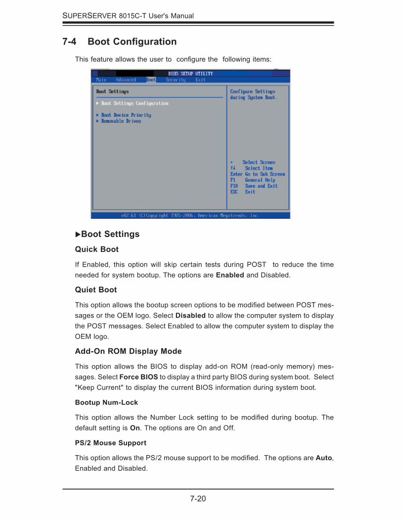
7-20
SUPERSERVER 8015C-T User's Manual
7-4 Boot Confi guration
This feature allows the user to confi gure the following items:
�Boot SettingsQuick Boot
If Enabled, this option will skip certain tests during POST to reduce the time needed for system bootup. The options are Enabled and Disabled.
Quiet Boot
This option allows the bootup screen options to be modifi ed between POST mes-sages or the OEM logo. Select Disabled to allow the computer system to display the POST messages. Select Enabled to allow the computer system to display the OEM logo.
Add-On ROM Display Mode
This option allows the BIOS to display add-on ROM (read-only memory) mes-sages. Select Force BIOS to display a third party BIOS during system boot. Select "Keep Current" to display the current BIOS information during system boot.
Bootup Num-Lock
This option allows the Number Lock setting to be modifi ed during bootup. The default setting is On. The options are On and Off.
PS/2 Mouse Support
This option allows the PS/2 mouse support to be modifi ed. The options are Auto, Enabled and Disabled.
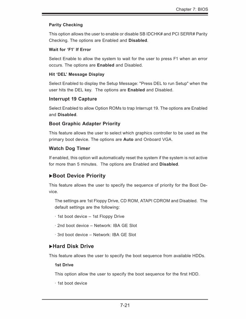
Chapter 7: BIOS
7-21
Parity Checking
This option allows the user to enable or disable SB IDCHK# and PCI SERR# Parity Checking. The options are Enabled and Disabled.
Wait for ‘F1’ If Error
Select Enable to allow the system to wait for the user to press F1 when an error occurs. The options are Enabled and Disabled.
Hit ‘DEL’ Message Display
Select Enabled to display the Setup Message: "Press DEL to run Setup" when the user hits the DEL key. The options are Enabled and Disabled.
Interrupt 19 Capture
Select Enabled to allow Option ROMs to trap Interrupt 19. The options are Enabled and Disabled.
Boot Graphic Adapter Priority
This feature allows the user to select which graphics controller to be used as the primary boot device. The options are Auto and Onboard VGA.
Watch Dog Timer
If enabled, this option will automatically reset the system if the system is not active for more than 5 minutes. The options are Enabled and Disabled.
�Boot Device PriorityThis feature allows the user to specify the sequence of priority for the Boot De-vice.
The settings are 1st Floppy Drive, CD ROM, ATAPI CDROM and Disabled. The default settings are the following:
· 1st boot device – 1st Floppy Drive
· 2nd boot device – Network: IBA GE Slot
· 3rd boot device – Network: IBA GE Slot
�Hard Disk DriveThis feature allows the user to specify the boot sequence from available HDDs.
1st Drive
This option allow the user to specify the boot sequence for the fi rst HDD.
· 1st boot device
7-22
SUPERSERVER 8015C-T User's Manual
�Removable DrivesThis feature allows the user to specify the boot sequence from available Remov-able Drives.
1st Drive/2nd Drive
This option allow the user to specify the boot sequence for the fi rst Removable Drive and the second Removable Drive.
The options are 1st Floppy Drive, USB: Pepper Virtual Disc 1 (2nd Drive), and Disabled.
�CD/DVD DrivesThis feature allows the user to specify the boot sequence from available CD/DVD-Drives.
1st Drive/2nd Drive
This option allows the user to specify the boot sequence for the First CD/DVD Drive and the Second CD/DVD Drive. The options are CD/DVD: PS-UJDA770, CD/DVD and Disabled.
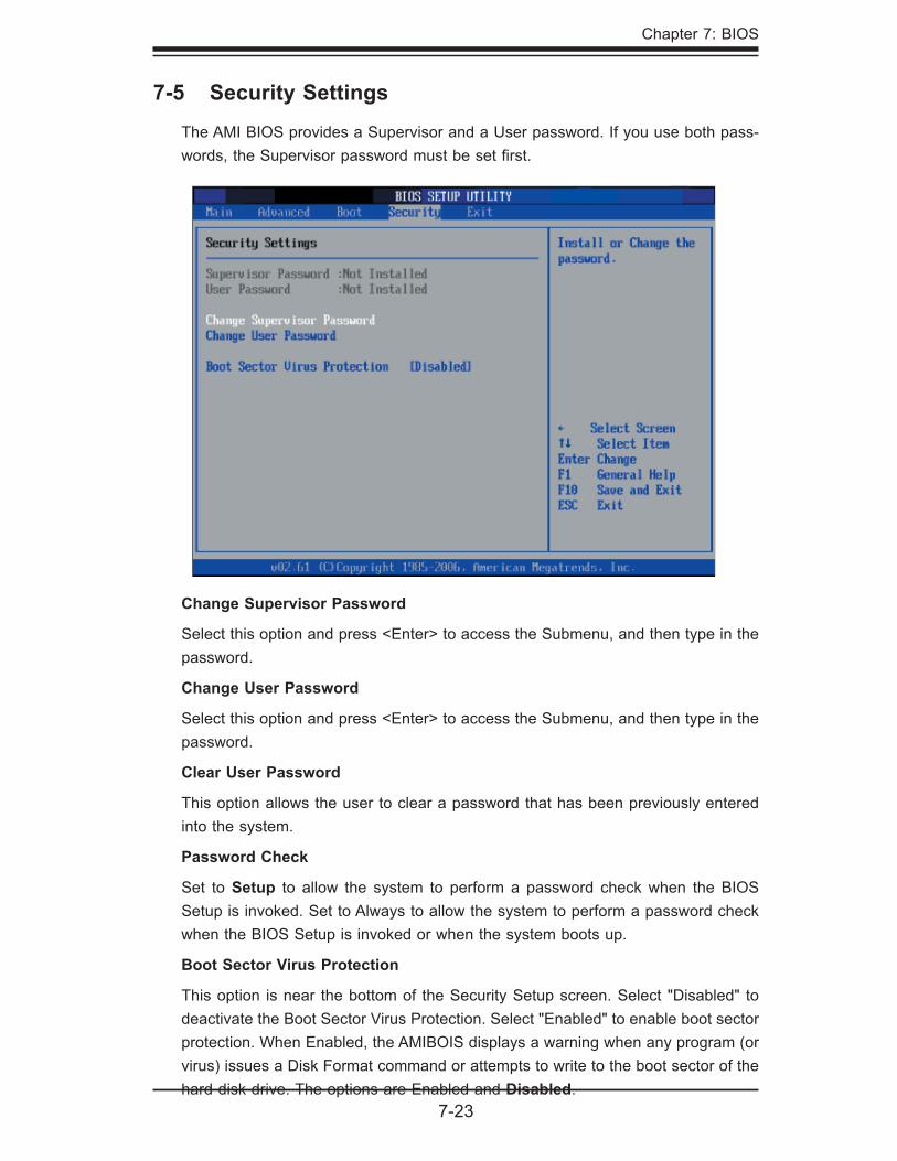
Chapter 7: BIOS
7-23
Change Supervisor Password
Select this option and press <Enter> to access the Submenu, and then type in the password.
Change User Password
Select this option and press <Enter> to access the Submenu, and then type in the password.
Clear User Password
This option allows the user to clear a password that has been previously entered into the system.
Password Check
Set to Setup to allow the system to perform a password check when the BIOS Setup is invoked. Set to Always to allow the system to perform a password check when the BIOS Setup is invoked or when the system boots up.
Boot Sector Virus Protection
This option is near the bottom of the Security Setup screen. Select "Disabled" to deactivate the Boot Sector Virus Protection. Select "Enabled" to enable boot sector protection. When Enabled, the AMIBOIS displays a warning when any program (or virus) issues a Disk Format command or attempts to write to the boot sector of the hard disk drive. The options are Enabled and Disabled.
7-5 Security Settings
The AMI BIOS provides a Supervisor and a User password. If you use both pass-words, the Supervisor password must be set fi rst.
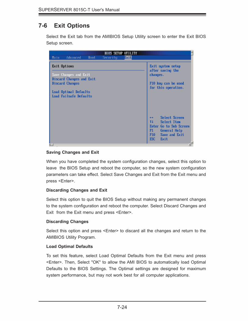
7-24
SUPERSERVER 8015C-T User's Manual
7-6 Exit Options
Select the Exit tab from the AMIBIOS Setup Utility screen to enter the Exit BIOS Setup screen.
Saving Changes and Exit
When you have completed the system confi guration changes, select this option to leave the BIOS Setup and reboot the computer, so the new system confi guration parameters can take effect. Select Save Changes and Exit from the Exit menu and press <Enter>.
Discarding Changes and Exit
Select this option to quit the BIOS Setup without making any permanent changes to the system confi guration and reboot the computer. Select Discard Changes and Exit from the Exit menu and press <Enter>.
Discarding Changes
Select this option and press <Enter> to discard all the changes and return to the AMIBIOS Utility Program.
Load Optimal Defaults
To set this feature, select Load Optimal Defaults from the Exit menu and press <Enter>. Then, Select "OK" to allow the AMI BIOS to automatically load Optimal Defaults to the BIOS Settings. The Optimal settings are designed for maximum system performance, but may not work best for all computer applications.
Chapter 7: BIOS
7-25
Load Fail-Safe Defaults
To set this feature, select Load Fail-Safe Defaults from the Exit menu and press <Enter>. The Fail-Safe settings are designed for maximum system stability, but not for maximum performance.

7-26
SUPERSERVER 8015C-T User's Manual
Notes
A-1
Appendix A: BIOS POST Messages
Appendix A
BIOS POST Messages
During the Power-On Self-Test (POST), the BIOS will check for problems. If a prob-lem is found, the BIOS will activate an alarm or display a message. The following is a list of such BIOS messages.
Failure Fixed DiskFixed disk is not working or not confi gured properly. Check to see if fi xed disk is at-tached properly. Run Setup. Find out if the fi xed-disk type is correctly identifi ed.
Stuck keyStuck key on keyboard.
Keyboard errorKeyboard not working.
Keyboard Controller FailedKeyboard controller failed test. May require replacing keyboard controller.
Keyboard locked - Unlock key switchUnlock the system to proceed.
Monitor type does not match CMOS - Run SETUPMonitor type not correctly identifi ed in Setup
Shadow Ram Failed at offset: nnnnShadow RAM failed at offset nnnn of the 64k block at which the error was de-tected.
System RAM Failed at offset: nnnnSystem RAM failed at offset nnnn of in the 64k block at which the error was de-tected.
Extended RAM Failed at offset: nnnn Extended memory not working or not confi gured properly at offset nnnn.
System battery is dead - Replace and run SETUPThe CMOS clock battery indicator shows the battery is dead. Replace the battery and run Setup to reconfi gure the system.
A-2
SUPERSERVER 8015C-T User's Manual
System CMOS checksum bad - Default confi guration usedSystem CMOS has been corrupted or modifi ed incorrectly, perhaps by an application program that changes data stored in CMOS. The BIOS installed Default Setup Values. If you do not want these values, enter Setup and enter your own values. If the error persists, check the system battery or contact your dealer.
System timer errorThe timer test failed. Requires repair of system board.
Real time clock error Real-Time Clock fails BIOS hardware test. May require board repair.
Check date and time settings BIOS found date or time out of range and reset the Real-Time Clock. May require setting legal date (1991-2099).
Previous boot incomplete - Default confi guration usedPrevious POST did not complete successfully. POST loads default values and offers to run Setup. If the failure was caused by incorrect values and they are not corrected, the next boot will likely fail. On systems with control of wait states, improper Setup settings can also terminate POST and cause this error on the next boot. Run Setup and verify that the waitstate confi guration is correct. This error is cleared the next time the system is booted.
Memory Size found by POST differed from CMOSMemory size found by POST differed from CMOS.
Diskette drive A errorDrive A: is present but fails the BIOS POST diskette tests. Check to see that the drive is defi ned with the proper diskette type in Setup and that the diskette drive is attached correctly.
Incorrect Drive A type - run SETUPType of fl oppy drive A: not correctly identifi ed in Setup.
System cache error - Cache disabledRAM cache failed and BIOS disabled the cache. On older boards, check the cache jumpers. You may have to replace the cache. See your dealer. A disabled cache slows system performance considerably.
CPU ID:CPU socket number for Multi-Processor error.
A-3
Appendix A: BIOS POST Messages
EISA CMOS not writeableServerBIOS2 test error: Cannot write to EISA CMOS.
DMA Test FailedServerBIOS2 test error: Cannot write to extended DMA (Direct Memory Access) registers.
Software NMI FailedServerBIOS2 test error: Cannot generate software NMI (Non-Maskable Interrupt).
Fail-Safe Timer NMI FailedServerBIOS2 test error: Fail-Safe Timer takes too long.
Device Address Confl ictAddress confl ict for specifi ed device.
Allocation Error for: deviceRun ISA or EISA Confi guration Utility to resolve resource confl ict for the specifi ed device.
CD ROM DriveCD ROM Drive identifi ed.
Entering SETUP ...Starting Setup program
Failing Bits: nnnnThe hex number nnnn is a map of the bits at the RAM address which failed the memory test. Each 1 (one) in the map indicates a failed bit. See errors 230, 231, or 232 above for offset address of the failure in System, Extended, or Shadow memory.
Fixed Disk nFixed disk n (0-3) identifi ed.
Invalid System Confi guration DataProblem with NVRAM (CMOS) data.
I/O device IRQ confl ictI/O device IRQ confl ict error.PS/2 Mouse Boot Summary Screen:PS/2 Mouse installed.
A-4
SUPERSERVER 8015C-T User's Manual
nnnn kB Extended RAM PassedWhere nnnn is the amount of RAM in kilobytes successfully tested.
nnnn Cache SRAM PassedWhere nnnn is the amount of system cache in kilobytes successfully tested.
nnnn kB Shadow RAM PassedWhere nnnn is the amount of shadow RAM in kilobytes successfully tested.
nnnn kB System RAM PassedWhere nnnn is the amount of system RAM in kilobytes successfully tested.
One or more I2O Block Storage Devices were excluded from the Setup Boot MenuThere was not enough room in the IPL table to display all installed I2O block-storage devices.
Operating system not foundOperating system cannot be located on either drive A: or drive C:. Enter Setup and see if fi xed disk and drive A: are properly identifi ed.
Parity Check 1 nnnnParity error found in the system bus. BIOS attempts to locate the address and display it on the screen. If it cannot locate the address, it displays ????. Parity is a method for checking errors in binary data. A parity error indicates that some data has been corrupted.
Parity Check 2 nnnnParity error found in the I/O bus. BIOS attempts to locate the address and display it on the screen. If it cannot locate the address, it displays ????.
Press <F1> to resume, <F2> to Setup, <F3> for previous Displayed after any recoverable error message. Press <F1> to start the boot process or <F2> to enter Setup and change the settings. Press <F3> to display the previous screen (usually an initialization error of an Option ROM, i.e., an add-on card). Write down and follow the information shown on the screen.
Press <F2> to enter SetupOptional message displayed during POST. Can be turned off in Setup.
A-5
Appendix A: BIOS POST Messages
PS/2 Mouse:PS/2 mouse identifi ed.
Run the I2O Confi guration UtilityOne or more unclaimed block storage devices have the Confi guration Request bit set in the LCT. Run an I2O Confi guration Utility (e.g. the SAC utility).
System BIOS shadowedSystem BIOS copied to shadow RAM.
UMB upper limit segment address: nnnnDisplays the address nnnn of the upper limit of Upper Memory Blocks, indicating released segments of the BIOS which can be reclaimed by a virtual memory man-ager.
Video BIOS shadowedVideo BIOS successfully copied to shadow RAM.

A-6
SUPERSERVER 8015C-T User's Manual
Notes
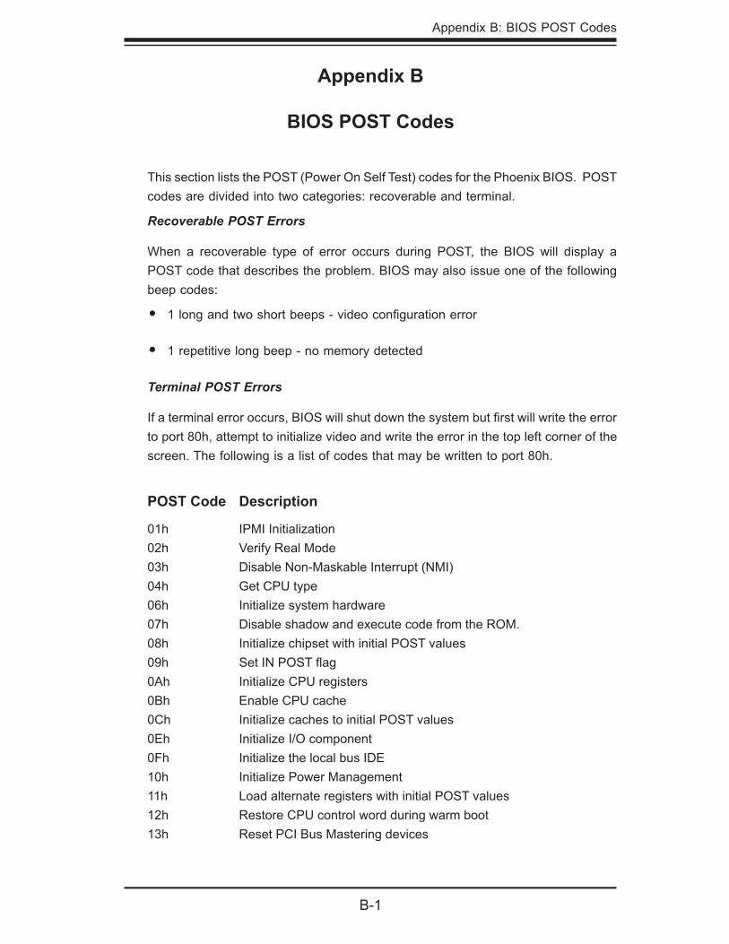
Appendix B: BIOS POST Codes
B-1
Appendix B
BIOS POST Codes
This section lists the POST (Power On Self Test) codes for the Phoenix BIOS. POST codes are divided into two categories: recoverable and terminal.
Recoverable POST Errors
When a recoverable type of error occurs during POST, the BIOS will display a POST code that describes the problem. BIOS may also issue one of the following beep codes:
1 long and two short beeps - video confi guration error
1 repetitive long beep - no memory detected
Terminal POST Errors
If a terminal error occurs, BIOS will shut down the system but fi rst will write the error to port 80h, attempt to initialize video and write the error in the top left corner of the screen. The following is a list of codes that may be written to port 80h.
•
•
POST Code Description
01h IPMI Initialization02h Verify Real Mode03h Disable Non-Maskable Interrupt (NMI)04h Get CPU type06h Initialize system hardware07h Disable shadow and execute code from the ROM.08h Initialize chipset with initial POST values09h Set IN POST fl ag0Ah Initialize CPU registers0Bh Enable CPU cache0Ch Initialize caches to initial POST values0Eh Initialize I/O component0Fh Initialize the local bus IDE10h Initialize Power Management11h Load alternate registers with initial POST values12h Restore CPU control word during warm boot13h Reset PCI Bus Mastering devices
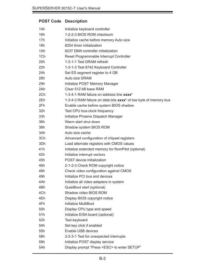
B-2
SUPERSERVER 8015C-T User's Manual
POST Code Description
14h Initialize keyboard controller16h 1-2-2-3 BIOS ROM checksum17h Initialize cache before memory Auto size18h 8254 timer initialization1Ah 8237 DMA controller initialization1Ch Reset Programmable Interrupt Controller20h 1-3-1-1 Test DRAM refresh22h 1-3-1-3 Test 8742 Keyboard Controller24h Set ES segment register to 4 GB28h Auto size DRAM29h Initialize POST Memory Manager2Ah Clear 512 kB base RAM2Ch 1-3-4-1 RAM failure on address line xxxx*2Eh 1-3-4-3 RAM failure on data bits xxxx* of low byte of memory bus2Fh Enable cache before system BIOS shadow32h Test CPU bus-clock frequency33h Initialize Phoenix Dispatch Manager36h Warm start shut down38h Shadow system BIOS ROM3Ah Auto size cache3Ch Advanced confi guration of chipset registers3Dh Load alternate registers with CMOS values41h Initialize extended memory for RomPilot (optional)42h Initialize interrupt vectors45h POST device initialization46h 2-1-2-3 Check ROM copyright notice48h Check video confi guration against CMOS49h Initialize PCI bus and devices4Ah Initialize all video adapters in system4Bh QuietBoot start (optional)4Ch Shadow video BIOS ROM4Eh Display BIOS copyright notice4Fh Initialize MultiBoot50h Display CPU type and speed51h Initialize EISA board (optional)52h Test keyboard54h Set key click if enabled55h Enable USB devices58h 2-2-3-1 Test for unexpected interrupts59h Initialize POST display service5Ah Display prompt “Press <ESC> to enter SETUP”
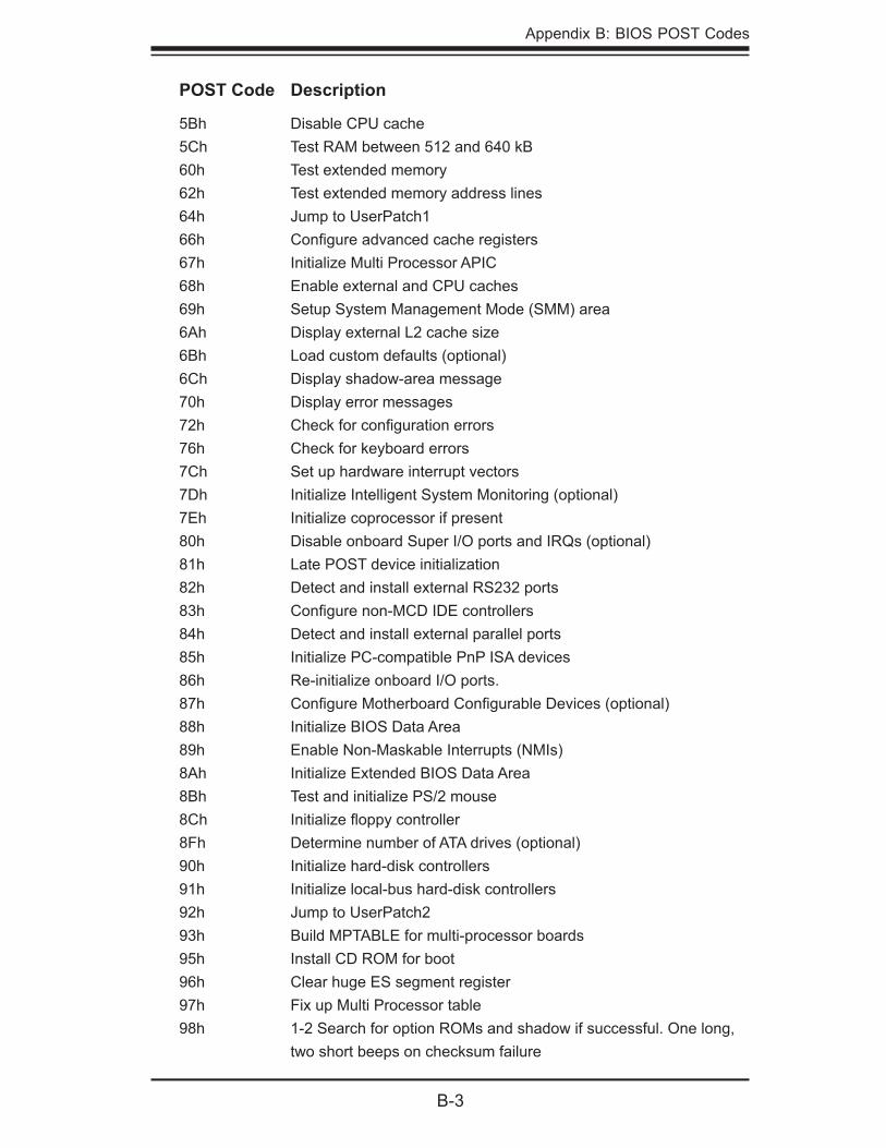
Appendix B: BIOS POST Codes
B-3
POST Code Description
5Bh Disable CPU cache5Ch Test RAM between 512 and 640 kB60h Test extended memory62h Test extended memory address lines64h Jump to UserPatch166h Confi gure advanced cache registers67h Initialize Multi Processor APIC68h Enable external and CPU caches69h Setup System Management Mode (SMM) area6Ah Display external L2 cache size6Bh Load custom defaults (optional)6Ch Display shadow-area message70h Display error messages72h Check for confi guration errors76h Check for keyboard errors7Ch Set up hardware interrupt vectors7Dh Initialize Intelligent System Monitoring (optional)7Eh Initialize coprocessor if present80h Disable onboard Super I/O ports and IRQs (optional)81h Late POST device initialization82h Detect and install external RS232 ports83h Confi gure non-MCD IDE controllers84h Detect and install external parallel ports85h Initialize PC-compatible PnP ISA devices86h Re-initialize onboard I/O ports.87h Confi gure Motherboard Confi gurable Devices (optional)88h Initialize BIOS Data Area89h Enable Non-Maskable Interrupts (NMIs)8Ah Initialize Extended BIOS Data Area8Bh Test and initialize PS/2 mouse8Ch Initialize fl oppy controller8Fh Determine number of ATA drives (optional)90h Initialize hard-disk controllers91h Initialize local-bus hard-disk controllers92h Jump to UserPatch293h Build MPTABLE for multi-processor boards95h Install CD ROM for boot96h Clear huge ES segment register97h Fix up Multi Processor table98h 1-2 Search for option ROMs and shadow if successful. One long, two short beeps on checksum failure
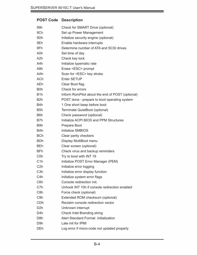
B-4
SUPERSERVER 8015C-T User's Manual
POST Code Description
99h Check for SMART Drive (optional)9Ch Set up Power Management9Dh Initialize security engine (optional)9Eh Enable hardware interrupts9Fh Determine number of ATA and SCSI drivesA0h Set time of dayA2h Check key lockA4h Initialize typematic rateA8h Erase <ESC> promptAAh Scan for <ESC> key strokeACh Enter SETUPAEh Clear Boot fl agB0h Check for errorsB1h Inform RomPilot about the end of POST (optional)B2h POST done - prepare to boot operating systemB4h 1 One short beep before bootB5h Terminate QuietBoot (optional)B6h Check password (optional)B7h Initialize ACPI BIOS and PPM StructuresB9h Prepare BootBAh Initialize SMBIOSBCh Clear parity checkersBDh Display MultiBoot menuBEh Clear screen (optional)BFh Check virus and backup remindersC0h Try to boot with INT 19C1h Initialize POST Error Manager (PEM)C2h Initialize error loggingC3h Initialize error display functionC4h Initialize system error fl agsC6h Console redirection init.C7h Unhook INT 10h if console redirection enabledC8h Force check (optional)C9h Extended ROM checksum (optional)CDh Reclaim console redirection vectorD2h Unknown interruptD4h Check Intel Branding stringD8h Alert Standard Format initializationD9h Late init for IPMIDEh Log error if micro-code not updated properly
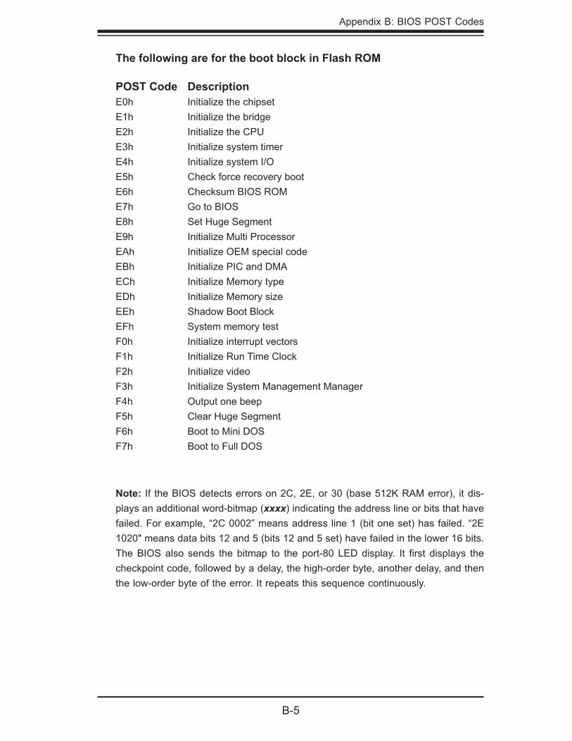
Appendix B: BIOS POST Codes
B-5
The following are for the boot block in Flash ROM
POST Code DescriptionE0h Initialize the chipsetE1h Initialize the bridgeE2h Initialize the CPUE3h Initialize system timerE4h Initialize system I/OE5h Check force recovery bootE6h Checksum BIOS ROME7h Go to BIOSE8h Set Huge SegmentE9h Initialize Multi ProcessorEAh Initialize OEM special codeEBh Initialize PIC and DMAECh Initialize Memory typeEDh Initialize Memory sizeEEh Shadow Boot BlockEFh System memory testF0h Initialize interrupt vectorsF1h Initialize Run Time ClockF2h Initialize videoF3h Initialize System Management ManagerF4h Output one beepF5h Clear Huge SegmentF6h Boot to Mini DOSF7h Boot to Full DOS
Note: If the BIOS detects errors on 2C, 2E, or 30 (base 512K RAM error), it dis-plays an additional word-bitmap (xxxx) indicating the address line or bits that have failed. For example, “2C 0002” means address line 1 (bit one set) has failed. “2E 1020" means data bits 12 and 5 (bits 12 and 5 set) have failed in the lower 16 bits. The BIOS also sends the bitmap to the port-80 LED display. It fi rst displays the checkpoint code, followed by a delay, the high-order byte, another delay, and then the low-order byte of the error. It repeats this sequence continuously.

B-6
SUPERSERVER 8015C-T User's Manual
Notes
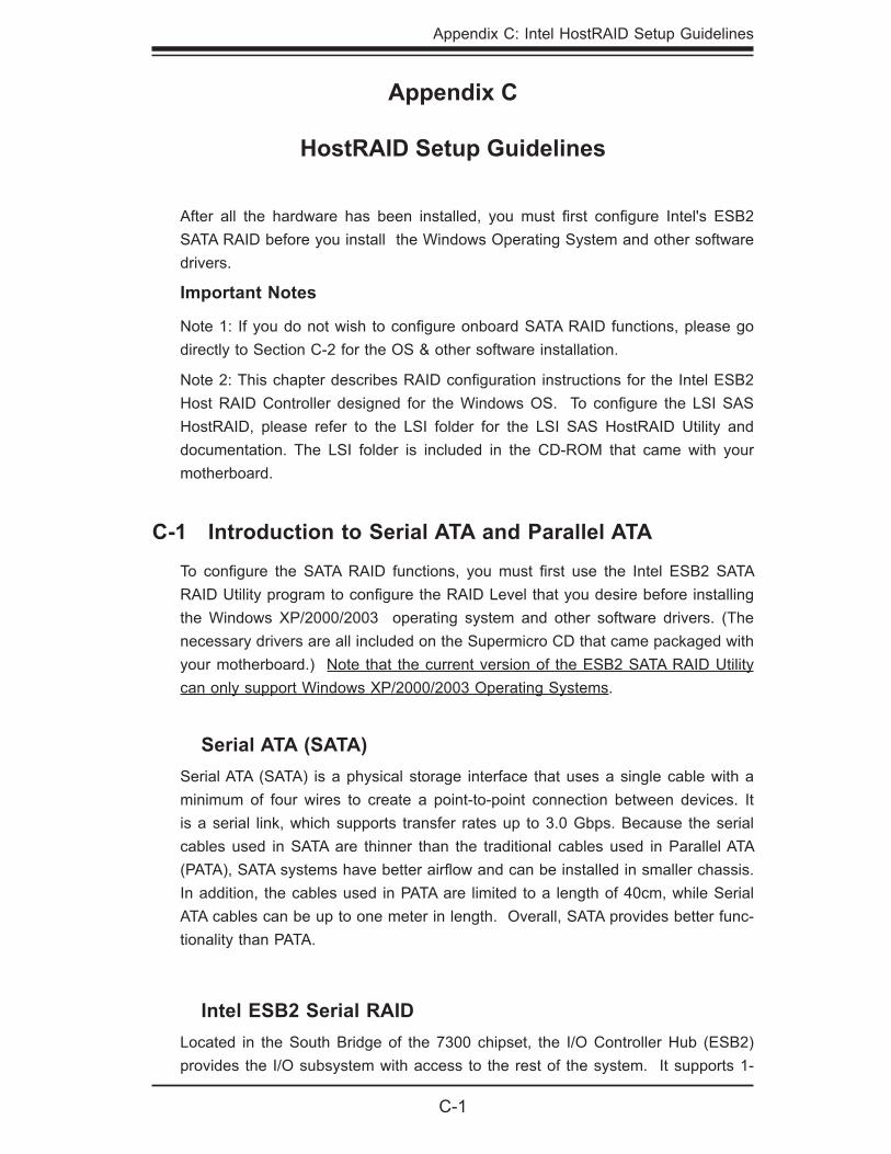
Appendix C: Intel HostRAID Setup Guidelines
C-1
Appendix C
HostRAID Setup Guidelines
After all the hardware has been installed, you must fi rst confi gure Intel's ESB2 SATA RAID before you install the Windows Operating System and other software drivers.
Important Notes
Note 1: If you do not wish to confi gure onboard SATA RAID functions, please go directly to Section C-2 for the OS & other software installation.
Note 2: This chapter describes RAID confi guration instructions for the Intel ESB2 Host RAID Controller designed for the Windows OS. To confi gure the LSI SAS HostRAID, please refer to the LSI folder for the LSI SAS HostRAID Utility and documentation. The LSI folder is included in the CD-ROM that came with your motherboard.
C-1 Introduction to Serial ATA and Parallel ATA
To confi gure the SATA RAID functions, you must fi rst use the Intel ESB2 SATA RAID Utility program to confi gure the RAID Level that you desire before installing the Windows XP/2000/2003 operating system and other software drivers. (The necessary drivers are all included on the Supermicro CD that came packaged with your motherboard.) Note that the current version of the ESB2 SATA RAID Utility can only support Windows XP/2000/2003 Operating Systems.
Serial ATA (SATA)Serial ATA (SATA) is a physical storage interface that uses a single cable with a minimum of four wires to create a point-to-point connection between devices. It is a serial link, which supports transfer rates up to 3.0 Gbps. Because the serial cables used in SATA are thinner than the traditional cables used in Parallel ATA (PATA), SATA systems have better airfl ow and can be installed in smaller chassis. In addition, the cables used in PATA are limited to a length of 40cm, while Serial ATA cables can be up to one meter in length. Overall, SATA provides better func-tionality than PATA.
Intel ESB2 Serial RAID Located in the South Bridge of the 7300 chipset, the I/O Controller Hub (ESB2) provides the I/O subsystem with access to the rest of the system. It supports 1-
C-2
SUPERSERVER 8015C-T User's Manual
The Intel HostRAID Confi gurationsThe following types of Intel's HostRAID confi gurations are supported:
RAID 0 (Data Striping): this writes data in parallel, interleaved ("striped") sections of two hard drives. Data transfer rate is doubled over using a single disk.
RAID1 (Data Mirroring): an identical data image from one drive is copied to another drive. The second drive must be the same size or larger than the fi rst drive.
RAID 10 (Striping & Mirroring): RAID 0 and 1 schemes are combined (without parity information) to get the benefi ts of both.
RAID 5: both data and parity information are striped and mirrored across three or more hard drives.
The Intel Matrix StorageThe Intel Matrix Storage, supported by the ESB2, allows the user to create RAID 0, RAID 1, RAID 10 and RAID 5 sets by using only four identical hard disk drives. The Intel Matrix Storage Technology creates two partitions on each hard disk drive and generate a virtual RAID 0, RAID 1, RAID 10 and RAID 5 sets. It also allows you the change the HDD partition size without any data.
Confi guring BIOS Settings
Press the <Del> key during system bootup to enter the BIOS Setup Utility. Note: If it is the fi rst time powering on the system, we recommend you load the Optimized Default Settings. If you have already done so, please skip to Step 3.
Use the arrow keys to select the "Exit" Settings. Once in the "Exit" settings, Scroll down to select "Load Optimized Default Settings" and press the <En-ter> key. Select "OK" to confi rm the selection. Press the <Enter> key to load the default settings for the BIOS.
Use the arrow keys to select the "Main" section in BIOS.
Scroll down to "SATA Controller Mode" and press the <Enter> key to select "Enhanced"
Scroll down to "SATA RAID Enabled" and press <Enter>. Then, select "En-abled."
1.
2.
3.
4.
5.
channel UltraATA/100 Bus Master IDE controller (PATA) and four Serial ATA (SATA) ports. The ESB2 supports the following PATA and SATA device confi gurations: Legacy mode and Native mode.
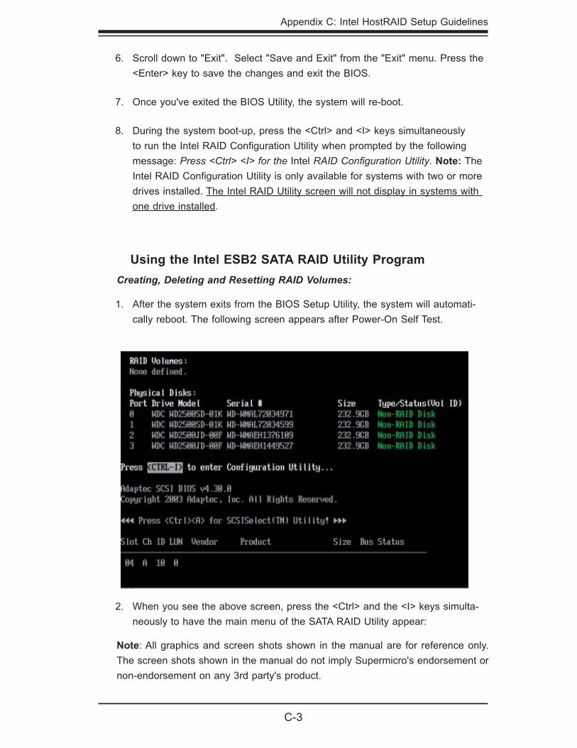
Appendix C: Intel HostRAID Setup Guidelines
C-3
Using the Intel ESB2 SATA RAID Utility ProgramCreating, Deleting and Resetting RAID Volumes:
After the system exits from the BIOS Setup Utility, the system will automati-cally reboot. The following screen appears after Power-On Self Test.
1.
Note: All graphics and screen shots shown in the manual are for reference only. The screen shots shown in the manual do not imply Supermicro's endorsement or non-endorsement on any 3rd party's product.
Scroll down to "Exit". Select "Save and Exit" from the "Exit" menu. Press the <Enter> key to save the changes and exit the BIOS.
Once you've exited the BIOS Utility, the system will re-boot.
During the system boot-up, press the <Ctrl> and <I> keys simultaneously to run the Intel RAID Confi guration Utility when prompted by the following message: Press <Ctrl> <I> for the Intel RAID Confi guration Utility. Note: The Intel RAID Confi guration Utility is only available for systems with two or more drives installed. The Intel RAID Utility screen will not display in systems with one drive installed.
6.
7.
8.
When you see the above screen, press the <Ctrl> and the <I> keys simulta-neously to have the main menu of the SATA RAID Utility appear:
2.
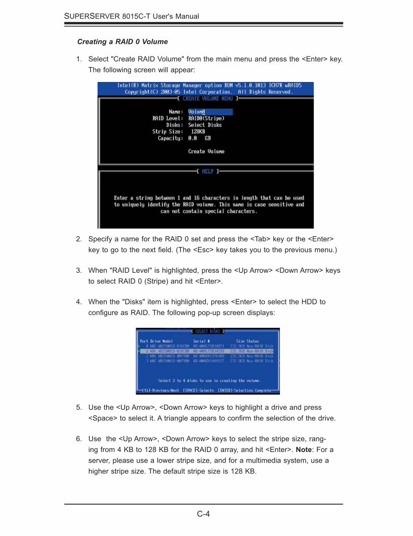
C-4
SUPERSERVER 8015C-T User's Manual
Creating a RAID 0 Volume
Select "Create RAID Volume" from the main menu and press the <Enter> key. The following screen will appear:
1.
Specify a name for the RAID 0 set and press the <Tab> key or the <Enter> key to go to the next fi eld. (The <Esc> key takes you to the previous menu.)
When "RAID Level" is highlighted, press the <Up Arrow> <Down Arrow> keys to select RAID 0 (Stripe) and hit <Enter>.
When the "Disks" item is highlighted, press <Enter> to select the HDD to confi gure as RAID. The following pop-up screen displays:
2.
3.
4.
Use the <Up Arrow>, <Down Arrow> keys to highlight a drive and press <Space> to select it. A triangle appears to confi rm the selection of the drive.
Use the <Up Arrow>, <Down Arrow> keys to select the stripe size, rang-ing from 4 KB to 128 KB for the RAID 0 array, and hit <Enter>. Note: For a server, please use a lower stripe size, and for a multimedia system, use a higher stripe size. The default stripe size is 128 KB.
5.
6.
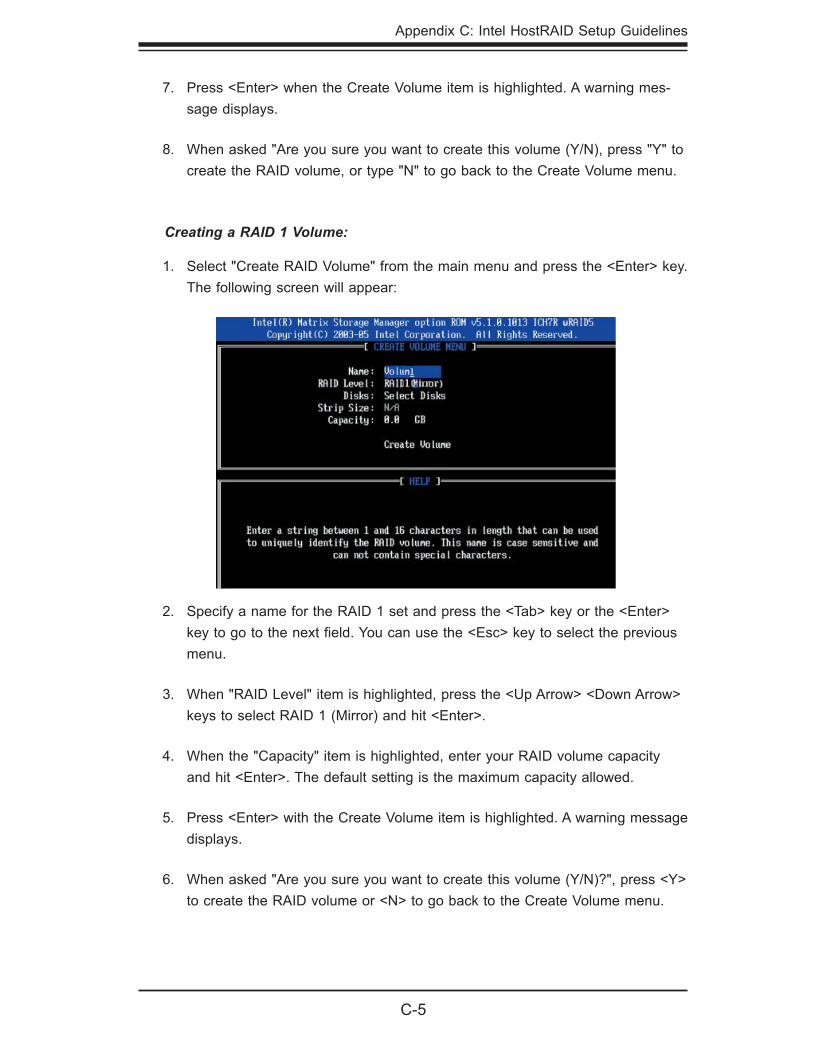
Appendix C: Intel HostRAID Setup Guidelines
C-5
Creating a RAID 1 Volume:
Select "Create RAID Volume" from the main menu and press the <Enter> key. The following screen will appear:
1.
Press <Enter> when the Create Volume item is highlighted. A warning mes-sage displays.
When asked "Are you sure you want to create this volume (Y/N), press "Y" to create the RAID volume, or type "N" to go back to the Create Volume menu.
7.
8.
Specify a name for the RAID 1 set and press the <Tab> key or the <Enter> key to go to the next fi eld. You can use the <Esc> key to select the previous menu.
When "RAID Level" item is highlighted, press the <Up Arrow> <Down Arrow> keys to select RAID 1 (Mirror) and hit <Enter>.
When the "Capacity" item is highlighted, enter your RAID volume capacity and hit <Enter>. The default setting is the maximum capacity allowed.
Press <Enter> with the Create Volume item is highlighted. A warning message displays.
When asked "Are you sure you want to create this volume (Y/N)?", press <Y> to create the RAID volume or <N> to go back to the Create Volume menu.
2.
3.
4.
5.
6.
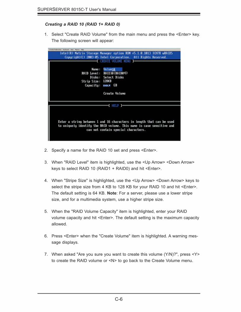
C-6
SUPERSERVER 8015C-T User's Manual
Creating a RAID 10 (RAID 1+ RAID 0)
Select "Create RAID Volume" from the main menu and press the <Enter> key. The following screen will appear:
1.
Specify a name for the RAID 10 set and press <Enter>.
When "RAID Level" item is highlighted, use the <Up Arrow> <Down Arrow> keys to select RAID 10 (RAID1 + RAID0) and hit <Enter>.
When "Stripe Size" is highlighted, use the <Up Arrow> <Down Arrow> keys to select the stripe size from 4 KB to 128 KB for your RAID 10 and hit <Enter>. The default setting is 64 KB. Note: For a server, please use a lower stripe size, and for a multimedia system, use a higher stripe size.
When the "RAID Volume Capacity" item is highlighted, enter your RAID volume capacity and hit <Enter>. The default setting is the maximum capacity allowed.
Press <Enter> when the "Create Volume" item is highlighted. A warning mes-sage displays.
When asked "Are you sure you want to create this volume (Y/N)?", press <Y> to create the RAID volume or <N> to go back to the Create Volume menu.
2.
3.
4.
5.
6.
7.
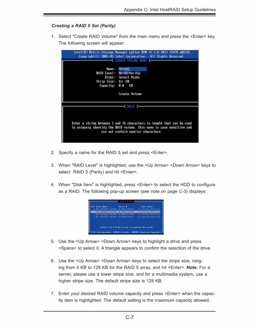
Appendix C: Intel HostRAID Setup Guidelines
C-7
Creating a RAID 5 Set (Parity)
Select "Create RAID Volume" from the main menu and press the <Enter> key. The following screen will appear:
1.
Specify a name for the RAID 5 set and press <Enter>.
When "RAID Level" is highlighted, use the <Up Arrow> <Down Arrow> keys to select RAID 5 (Parity) and hit <Enter>.
When "Disk Item" is highlighted, press <Enter> to select the HDD to confi gure as a RAID. The following pop-up screen (see note on page C-3) displays:
2.
3.
4.
Use the <Up Arrow> <Down Arrow> keys to highlight a drive and press <Space> to select it. A triangle appears to confi rm the selection of the drive.
Use the <Up Arrow> <Down Arrow> keys to select the stripe size, rang-ing from 4 KB to 128 KB for the RAID 5 array, and hit <Enter>. Note: For a server, please use a lower stripe size, and for a multimedia system, use a higher stripe size. The default stripe size is 128 KB.
Enter your desired RAID volume capacity and press <Enter> when the capac-ity item is highlighted. The default setting is the maximum capacity allowed.
5.
6.
7.
C-8
SUPERSERVER 8015C-T User's Manual
Deleting a RAID Volume
Press Enter when the Create Volume item is highlighted. A warning message displays.
When asked "Are you sure you want to create this volume (Y/N), press <Y> to create the RAID volume or <N> to go back to the Create Volume menu.
8.
9.
!Warning: Be sure to back up your data before deleting a RAID set. You will lose all data on the disk drives when deleting a RAID set.
From the main menu, select "Delete RAID Volume" and press <Enter>.
Use the <Up Arrow> <Down Arrow> keys to select the RAID set you want to delete and press <Del>. A Warning message displays.
When asked "Are you sure you want to delete this volume (Y/N)?", press <Y> to delete the RAID volume or <N> to go back to the Delete Volume menu.
1.
2.
3.
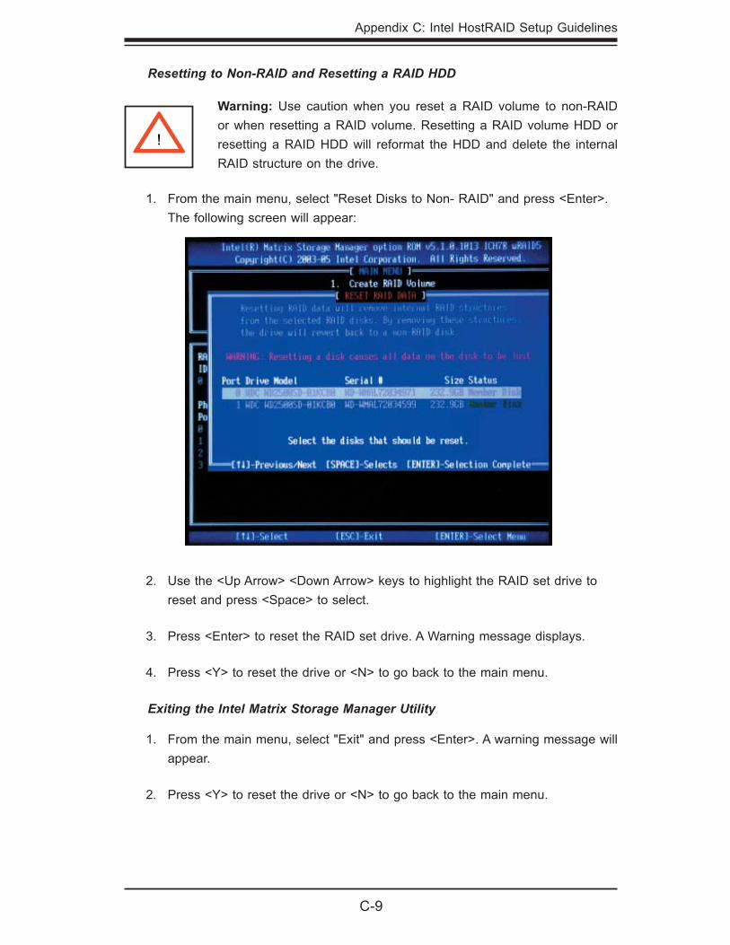
Appendix C: Intel HostRAID Setup Guidelines
C-9
From the main menu, select "Reset Disks to Non- RAID" and press <Enter>. The following screen will appear:
1.
Warning: Use caution when you reset a RAID volume to non-RAID or when resetting a RAID volume. Resetting a RAID volume HDD or resetting a RAID HDD will reformat the HDD and delete the internal RAID structure on the drive.
!
Resetting to Non-RAID and Resetting a RAID HDD
Use the <Up Arrow> <Down Arrow> keys to highlight the RAID set drive to reset and press <Space> to select.
Press <Enter> to reset the RAID set drive. A Warning message displays.
Press <Y> to reset the drive or <N> to go back to the main menu.
Exiting the Intel Matrix Storage Manager Utility
From the main menu, select "Exit" and press <Enter>. A warning message will appear.
Press <Y> to reset the drive or <N> to go back to the main menu.
2.
3.
4.
1.
2.
C-10
SUPERSERVER 8015C-T User's Manual
C-2 Installing Windows XP/2000/2003 for RAID Systems
Installing a New Operating System
Insert the Microsoft the Windows XP/2000/2003 Setup CD in the DVD/CD drive, and the system will start booting up from the CD.
Press the <F6> key when the message "Press F6 if you need to install a third party SCSI or RAID driver" displays.
When the Windows XP/2000/2003 Setup screen appears, press "S" to specify additional device(s).
Insert the "Intel AA RAID XP/2000/2003 Driver for ESB2" driver diskette into the fl oppy drive and press <Enter>.
Choose the Intel® ESB2 SATA RAID controller from the list indicated in the XP/2000/2003 Setup Screen, and press the <Enter> key.
Press the <Enter> key to continue the installation process. (If you need to specify any additional devices to be installed, do so at this time.) Once all devices are specifi ed, press the <Enter> key to continue with the installation.
From the Windows XP/2000/2003 Setup screen, press the <Enter> key. The XP/2000/2003 Setup will automatically load all device fi les and then continue the Windows XP/2000/2003 installation.
After the Windows XP/2000/2003 OS installation is completed, the system will automatically reboot.
Note: the current version of the ESB2 SATA RAID Utility can only support the Windows XP/2000/2003 Operating System.
1.
2.
3.
4.
5.
6.
7.
8.
D-1
Appendix D: System Specifi cations
Appendix D
System Specifi cations
Processors Four Intel Xeon 7300/7200 sequence processors (130W CPUs not supported) Note: Please refer to our web site for a complete listing of supported processors.
Chipset Intel 7300
BIOS 8 Mb AMIBIOS® Flash ROM
Memory Capacity Twenty-four 240-pin DIMM sockets supporting up to 192 GB of FBD ECC DDR2-667/533 SDRAM Note: See the memory section in Chapter 5 for details.
SATA Controller Intel on-chip controller for 3 Gb/s Serial ATA (RAID 0, 1, 10 and 5 support)
Drive Bays Three (3) hot-swap drive bays to house three (3) standard SATA drives
Peripheral Drives/Bays One (1) slim DVD-ROM drive
Expansion Slots Supports the use of one standard size PCI-Express x8 add-on card
Serverboard X7QCE (proprietary ATX form factor) Dimensions: 16" x 14.3" (406 x 363 mm)
Chassis SC818TQ-1000 (1U rackmount) Dimensions (both): (WxHxD) 17.2 x 1.7 x 27.75 in. (473 x 43 x 705 mm)
D-2
SUPERSERVER 8015C-T User's Manual
Weight Gross (Bare Bone): 43 lbs. (19.5 kg.)
System Cooling Six (6) paired sets of 4-cm counter-rotating cooling fans (fan speed controlled by BIOS setting)
System Input Requirements AC Input Voltage: 100-240 VAC Rated Input Current: 7A (115V) to 15A (240V) Rated Input Frequency: 50-60 Hz
Power Supply Rated Output Power: 1000W w/PFC (Part# PWS-1K01-1R) Rated Output Voltages: +3.3V (20A), +5V (20A), +12V (83A), -12V (0.6A), +5Vsb (4A)
BTU Rating 5278 BTUs/hr (for rated output power of 1000 W)
Operating Environment Operating Temperature: 10º to 35º C (50º to 95º F) Non-Operating Temperature: -40º to 70º C (-40º to 158º F) Operating Relative Humidity: 8% to 90% (non-condensing) Non-Operating Relative Humidity: 5 to 95% (non-condensing)
Regulatory Compliance Electromagnetic Emissions: FCC Class A, EN 55022 Class A, EN 61000-3-2/-3-3, CISPR 22 Class A
Electromagnetic Immunity: EN 55024/CISPR 24, (EN 61000-4-2, EN 61000-4-3, EN 61000-4-4, EN 61000-4-5, EN 61000-4-6, EN 61000-4-8, EN 61000-4-11)
Safety: EN 60950/IEC 60950-Compliant UL Listed (USA) CUL Listed (Canada) TUV Certifi ed (Germany) CE Marking (Europe)
D-3
Appendix D: System Specifi cations
California Best Management Practices Regulations for Perchlorate Materials: This Perchlorate warning applies only to products containing CR (Manganese Dioxide) Lithium coin cells. “Perchlorate Material-special handling may apply. See www.dtsc.ca.gov/hazardouswaste/perchlorate”

D-4
SUPERSERVER 8015C-T User's Manual
Notes