- TECHNOLOGY AND INSTITUTION - ICEF Innovation … Roadmap for Mobility Electric Energy Storage...
57
ENERGY STORAGE ROADMAP - TECHNOLOGY AND INSTITUTION – November 2017
Transcript of - TECHNOLOGY AND INSTITUTION - ICEF Innovation … Roadmap for Mobility Electric Energy Storage...

ENERGY STORAGE ROADMAP - TECHNOLOGY AND INSTITUTION –
November 2017


i
Table of contents Executive Summary ............................................................................................................... ii About the Authors ................................................................................................................. vi Acknowledgements ............................................................................................................... vi 1. Introduction ........................................................................................................................ 1
1.1 Objectives ..................................................................................................................... 1 1.2 Background of the Study .............................................................................................. 1 1.3 Significance of Roadmaps in the Energy Storage Field ................................................ 1 1.4 Survey of Existing Energy Storage Roadmaps ............................................................. 3
1.4.1 Roadmaps of International Organizations .............................................................. 3 1.4.2 Roadmaps of Governments and Industrial Associations......................................... 4
1.5 Scope of Energy Storage Technology Roadmap .......................................................... 7 2. Roadmap for Stationary Electric Energy Technology ......................................................... 8
2.1 Technologies for Stationary Electric Energy Storage .................................................... 8 2.1.1 Pumped-Storage Hydropower (PSH) ..................................................................... 8 2.1.2 Compressed Air Energy Storage (CAES) & Liquid Air Energy Storage (LAES) ...... 9 2.1.3 Superconducting Magnetic Energy Storage (SMES) ............................................ 11 2.1.4 Flywheel ............................................................................................................... 12 2.1.5 Supercapacitor ..................................................................................................... 13 2.1.6 Lead Acid Battery ................................................................................................. 14 2.1.7 Nickel-metal Hydride Battery ................................................................................ 15 2.1.8 Lithium Ion Battery ............................................................................................... 16 2.1.9 Sodium Sulfur Battery (NaS Battery) .................................................................... 18 2.1.10 Redox Flow Battery ............................................................................................ 19 2.1.11 All-solid-state Battery ......................................................................................... 21 2.1.12 Metal Air Battery................................................................................................. 23 2.1.13 Power to X (X= Hydrogen, Gas etc.) .................................................................. 24
2.2. Path to Innovation and Spread of Technologies......................................................... 26 2.2.1 Current Status of Stationary Electric Energy Storage Technology ........................ 26 2.2.2 Policy Support and Institution for Stationary Electric Energy Storage Market ....... 27
2.3 Roadmap for Stationary Electric Energy Storage Technologies .................................. 29 3. Roadmap for Mobility Electric Energy Storage Technology .............................................. 32
3.1 Technologies for Mobility Electric Energy Storage ...................................................... 32 3.1.1 Battery for Electric Vehicles ................................................................................. 32 3.1.2 Electric Vehicle Charger ....................................................................................... 34
3.2 Path to Innovation and Spread of Technologies.......................................................... 35 3.2.1 Current Status of Mobility Electric Energy Storage Technology ............................ 35 3.2.2 Public Support and Institution for Mobility Electric Energy Storage Market ........... 35
3.3 Roadmap for Mobility Electric Energy Storage Technology......................................... 38 4. Roadmap for Stationary Thermal Energy Storage Technology ......................................... 40
4.1 Technologies for Stationary Thermal Energy Storage ................................................. 40 4.1.1 District Heating & Cooling .................................................................................... 40 4.1.2 Underground Thermal Energy Storage ................................................................. 41
4.2. Path to Innovation and Spread of Technologies......................................................... 44 4.2.1 Current Status of Stationary Thermal Energy Storage Technology ...................... 44 4.2.2 Policy Support and Institution for Stationary Electric Energy Storage Market ....... 45
4.3 Roadmap for Stationary Thermal Energy Storage Technologies................................. 45 5. Proposal ........................................................................................................................... 47 6. References....................................................................................................................... 48

ii
Executive Summary (1) Background and Purposes
Innovation for Cool Earth Forum (ICEF) concept pursues long term net-zero emissions through innovation. Energy storage will work as one of the important enabling technologies to assist the transformation. According to Energy Technology Perspective (ETP) 2017 released from the International Energy Agency (IEA), the IEA estimates that 1,365 GW of storage technologies have to be deployed for stationary electric energy storage applications, and 28 TWh for electric vehicle batteries have to be deployed by 2060 in order to satisfy the two degree scenario. In order to pursue the possibility of achieving this technology deployment, we have studied the technologies to clarify the development targets and support policies and institutions . (2) Structure and Content of the Technology Roadmap
We surveyed the roadmaps prepared by international organizations, national governments, local governments, and industrial associations. We found that their descriptions and research and development (R&D) activities mainly focus on three categories; 1) stationary electric energy storage technology, 2) mobility electric energy storage technology, and 3) stationary thermal energy storage technology. This roadmap summarizes the current status of energy storage technologies and clarifies required R&D targets and support policies. (3) Research and Development (R&D) and Systems Necessary for Realizing 100% Renewable Power Society
Energy storage technology can enhance energy system flexibility, and it fills the gap between electricity and heat supply-demand in terms of the time and space dimensions. Energy storage technology brings various benefits: improving resource use efficiency, integrating high level variable renewable resources, end-use sector electrification especially in transport, supporting the production of energy where it is consumed, increasing energy access, and improving electricity grid stability, flexibility, reliability, and resilience. For this reason, these technologies should be designed in the flexibility technology portfolio. In order to satisfy two degree scenario, huge amounts of storage technology will have to be deployed and further R&D for cost reduction and performance improvement is essential, or this will be never achieved without technology innovations. In addition, market and institutional issues are important to recover the investment in storage technology. (4) Recommendations
The roadmap is directed towards developing and introducing technologies that will reduce CO2 emissions, a common goal to be pursued with worldwide cooperation, rather than towards the individual goals of national or local governments and industries. With this framework, we would like to deliver the following three recommendations to the world: - Sharing the importance of the energy storage with the whole of global society - Involving stakeholders in government, municipalities, and the private sector at an early stage - Sharing technologies, policies and information for their diffusion based on the roadmap.

iii
Figure ES-1 Technology categories of Roadmaps
Table ES-1 List of technologies included in the roadmap
Stationary Electric Energy Storage Technology Pumped-Storage Hydropower (PSH), Compressed Air Energy Storage (CAES), Liquid Air Energy Storage (LAES), Superconducting Magnetic Energy Storage (SMES), Flywheel, Supercapacitor, Lead Acid Battery, Nickel-metal Hydride Battery, Lithium Ion Battery, Sodium Sulfur Battery (NAS Battery), Redox Flow Battery, All-solid –state Lithium Battery, Metal Air Battery, Power to X (X=Hydrogen, gas, etc.)
Mobility Electric Energy Storage Technology Battery Technologies for Electric Vehicle (Nickel-metal Hydride Battery, Lithium Ion Battery, All-solid-state Lithium Battery, Metal Air Battery), Electric Vehicle Charger, Power to Grid
Stationary Thermal Energy Storage Technology District Heating & Cooling (Ice Storage), Underground Storage, Pit Storage, Molten Salt, Thermochemical

iv
Figure ES-2 Roadmap for Stationary Electric Energy Storage Technologies
Figure ES-3 Roadmap for Mobility Electric Energy Storage Technologies

v
Figure ES-4 Roadmap for Stationary Thermal Energy Storage Technologies

vi
About the Authors
This roadmap was written by the following organization to facilitate discussion at the 2017 Innovation for Cool Earth Forum and for release at UNFCCC/COP23: The Institute of Applied Energy
(http://www.iae.or.jp/e/) The Institute of Applied Energy (IAE) is a nonprofit organization conducting technology
related research in broad energy areas. To secure stable energy supplies and address global environmental issues, strategic planning and implementation from long-term and global perspectives are prerequisites. The IAE conducts studies and organizes projects with broad network among industry, academia and the government. The activities of IAE are supported by the contributions from industry members and research contracts with government agencies, private industries, etc.
Innovation for Cool Earth Forum (http://www.icef-forum.org/)
The Innovation for Cool Earth Forum (ICEF) is aimed at addressing climate change through innovation. ICEF investigates via discussion what innovative measures should be developed, how innovation should be promoted and how cooperation should be enhanced among stakeholders in fighting climate change.
ICEF holds its annual meeting every October in Tokyo, Japan, gathering policymakers, businesses and researchers from around the globe. The ICEF Steering Committee helps make decisions regarding the agenda and program to reflect the wide range of views of the international community. The ICEF Roadmap Project aims to help promote vision sharing and deepen discussions for developing and deploying low carbon technologies.
Acknowledgements
We are deeply grateful to the Ministry of Economy, Trade and Industry (METI) and New Energy and Industrial Technology Development Organization (NEDO), Japan, for launching and supporting the ICEF Innovation Roadmap Project of which this is a part. We would like to convey our sincere appreciation to Dr. Kazumi Tanimoto, Dr. Hironori Kobayashi, Dr. Hikari Sakaebe, Dr. Masahiro Shikano [Advanced Industrial Science and Technology (AIST)], and Mr. Koichi Yamamoto [National Institute of Technology and Evaluation (NITE)] for valuable expertise information and comments through interviews. We are grateful for the presentations and information by Dr. Hiroshi Asano [Central Research Institute of Electric Power Industry (CRIEPI)], Mr. David Turk [International Energy Agency (IEA)], Mr. Ravi Seethapathy [Biosirus Inc.], Dr. Kari Maki [VTT Technical Research Center of Finland], and Prof. Simon Furbo [Technical University of Denmark] during the energy storage session of ICEF 4th annual meeting.

1
1. Introduction
1.1 Objectives It is now clear that greenhouse gas emissions worldwide will continue on an increasing
trend until about 2030, when summing up the goals of the countries (for 2025 or 2030) for the reduction of greenhouse gases submitted, called INDC (Intended Nationally Determined Contributions) in preparation for the 21st session of the Conference of the Parties (COP21) to the United Nations Framework Convention on Climate Change.
On the other hand, the accelerated introduction of breakthrough technology related to energy and the environment is essential on a long-term basis in order to achieve the goal of keeping the post-industrial revolution temperature rise at 2 deg C or less in line with the Paris Agreement adopted in COP21. “Mission Innovation” was proposed under COP21 with the support of 20 countries, resulting in agreement on further promotion of investment in research and development. In addition, harmonization with innovation activities in the private sector was advocated, and this led to a renewal of the industry’s understanding of the importance of breakthrough technology.
As a result of discussions in the Steering Committee, it was decided in ICEF2017 to develop a roadmap for facilitating the development and introduction of technology related to Energy Storage.
1.2 Background of the Study Roadmaps for facilitating the development and introduction of technology related to
energy storage have been formulated by international organizations, national and local governments, industrial associations, non-governmental organizations and so on. In developing the ICEF2017 Roadmap this time, existing major roadmaps were referred to, and the direction of the facilitation of the development and introduction of technology was evaluated and organized.
The ICEF concept pursues long term net-zero emissions through innovation. To assist the transformation, energy storage will work as one of the important enabling technologies.
1.3 Significance of Roadmaps in the Energy Storage Field Figure 1.3.0-1 represents the global energy system in 2060 created from IEA ETP
2017’s two-degree scenario data. A large share of supply and power supply is covered by renewable energy in total, and electricity and biofuel occupy a large share of the transport sector. This scenario cannot be achieved without energy technology innovation. Energy storage technology can enhance energy system flexibility. It fills the gap between electricity and/or heat supply-demand in terms of time and/or space. Benefits of storage technologies are improving resource use efficiency, integrating high level variable renewable resources, end-use sector electrification especially in transport, supporting production of energy where it is consumed, increasing energy access, and improving electricity grid stability, flexibility, reliability, and resilience.

2
Figure1.3.0-1 Energy System Transformation in 2060 – Two-Degree Scenario
According to IEA ETP2017, 159 GW of energy storage was deployed in 2015; 96% of
this was accounted for by pumped storage hydropower. THE IEA estimates that 1,365 GW of storage technologies will be deployed for stationary electric energy storage applications, and 28 TWh for electric vehicle batteries will be deployed in 2060 in the two degree scenario. Without technology innovations, this transformation will be never achieved. For this reason, we propose technological roadmap for energy storage technologies as a guide for international cooperation and stakeholder involvement to assist further deployment of storage technologies.

3
1.4 Survey of Existing Energy Storage Roadmaps Various roadmaps related to energy storage have been formulated and made public by
various international organizations, national governments, local governments, industrial associations, and non-governmental organizations. Figure 1.4.0-1 shows organizations that have developed representative roadmaps, by plotting them on a world map. Many roadmaps have been published by IEA, IRENA, EU countries, THE USA, Japan, Australia, etc.
Figure 1.4.0-1 World Atlas of Energy Storage Roadmaps
1.4.1 Roadmaps of International Organizations 1.4.1.1 International Energy Agency (IEA) 1) Technology Roadmap Energy Storage [1] Author: IEA Date of publication: 2014.3 Summary:
This roadmap covers electric and thermal energy storage technologies, and provides the maturity and costs of each energy storage technology. It also clarifies the actions and milestones for energy storage technology development. 2) Technology Roadmap Electric and plug-in hybrid electric vehicles [2]
Author: IEA Date of publication: 2011.6 Summary:
This roadmap sets the targets to achieve the widespread adoption and use of EVs and PHEVs, which will represent more than 50% of annual LDV (Light Duty Vehicle) sales by 2050. In addition, this roadmap sets the strategic goals to achieve it, identifies the steps, and shows how government policy can support it.

4
1.4.1.2 International Renewable Energy Agencies (IRENA) 1) Renewables and Electricity Storage [3] Author: IRENA Date of publication: 2015.6 Summary:
This roadmap is made to assess pathways for doubling the share of renewable energy by 2030, and identifies the actions for technology development, investment and policy development on a country-based analysis. In addition, a cost and value analysis is also made for electric energy storage technologies.
1.4.2 Roadmaps of Governments and Industrial Associations 1.4.2.1 Japan 1) Energy Related Technology Roadmap (in Japanese) [4]
Author: METI Date of publication: 2014.12 Summary:
This roadmap summarizes the current status of worldwide R&D activities of energy related technologies, and sets the concrete goals of each technology toward 2050. This roadmap deals with energy storage technologies, including electric energy storage, thermal energy storage, and electric vehicles batteries.
2) Battery Roadmap2013 (in Japanese) [5]
Author: NEDO Date of publication: 2013.8 Summary:
This roadmap summarizes the current status of R&D activities of battery technologies, especially focusing on the lithium ion battery technologies, and sets the target of battery technology for both stationary and mobility applications toward 2030. 3) NESTI 2050 (in Japanese) [6]
Author: Council for Science, Technology and Innovation, Cabinet Office Date of publication: 2017.9 Summary:
This roadmap deals with a wide variety of technologies, including battery and power electronics technologies, which contribute to mitigating GHG emissions. Detailed targets are set for each technology toward 2050. It also sets milestones and crucial stage gates for each technology. 1.4.2.2 USA 1) Advancing and Maximizing the Value of Energy Storage Technology [7]
Author: California ISO Date of publication: 2014.12 Summary:
This roadmap focuses on actions to address three categories of challenges; 1) expanding revenue opportunities, 2) reducing the costs of integrating and connecting to the grid, 3) streamlining and spelling out the policies and the processes to increase certainty. The action items are listed up and their stakeholders and priorities are clarified. 2) Electrochemical Energy Storage Technical Team Roadmap [8]

5
Author: U.S.DRIVE1 Date of publication: 2013.6 Summary:
This roadmap describes ongoing and planned efforts to develop electrochemical energy storage technologies for plug-in hybrid vehicles (PHEVs). It sets detailed end-of-life targets for cells and PHEV systems, and sets milestones for research and development for energy storage batteries. 3) Energy Storage Roadmap for New York’s Electric Grid [9] Author: New York Battery and Energy Storage Technology Consortium Date of publication: 2016.1 Summary:
In the 2012 New York Energy Storage Roadmap, NY-BEST set a ten-year goal to have 1GW of storage on the grid. In this roadmap, new goals are set to have 2 GW of multi-hour storage capacity on New York’s electric grid by 2025 and 4 GW by 2030, taking into account the recent dramatic changes in the energy system. 1.4.2.3 EU 1) European Energy Storage Technology Development Roadmap towards 2030 [10]
Author: European Association for Storage of Energy; EASE / European Energy Research Alliance; EERA Date of publication: 2013 Summary:
This roadmap describes future European needs for energy storage in the period towards 2020-2030, and identifies the most pressing technology development priorities for the European energy storage industry 2) European Energy Storage Technology Development Roadmap 2017 Update [11] Author: European Association for Storage of Energy; EASE / European Energy Research Alliance; EERA Date of publication: 2017 Summary:
This roadmap updates the former European Energy storage technology roadmap, and provides a comprehensive overview of the energy storage technologies being developed in Europe today and identifies the most pressing research, development and demonstration needs in the coming decades. 3) Heat Roadmap Europe 2050 [12] Author: Connolly, D., Mathiesen, B.V., Ostergaard, P.A., Moller, B., B.,Nielsen, S., Lund, H., Trier, D. [Aalborg University] Date of publication: 2013.10 Summary:
This roadmap is the first study of district heating on EU 27 countries. This includes a geographical mapping of energy demand and supply, and the goal for the share that district heating will occupy for space heating and hot water supply in these countries is set at 50% in 2050.
1 U.S. DRIVE, which stands for United States Driving Research and Innovation for Vehicle efficiency and Energy sustainability, is a
government-industry partnership among the U.S. Department of Energy; USCAR, representing FCA US LLC, Ford Motor Company and General Motors; five energy companies – BP America, Chevron Corporation, ExxonMobil Corporation, Phillips 66 Company, and Shell Oil Products US; two utilities – Southern California Edison and Michigan-based DTE Energy; and the Electric Power Research Institute (EPRI).

6
1.4.2.4 Germany Technology Roadmap Energy Storage for Electric Mobility 2030 [13] Author: Fraunhofer Institute for Systems and Innovation Research ISI Date of publication: 2015.4 Summary:
This roadmap summarizes and outlines the current status of battery technologies for electric vehicles, and sets the battery development targets toward 2030. The detailed targets for their properties, such as energy density, power density, lifetime, cost and efficiency are identified and set toward 2030. 1.4.2.5 Netherlands Energy Storage Roadmap NL 2030 [14]
Author: KEMA Nederland B.V. Date of publication: 2015.4 Summary:
A scenario analysis and economic analysis for energy storage technologies is conducted toward 2030, and two action plans for Netherland are proposed. One is to stimulate and support Research & Development projects, and the other is to remove barriers in the legislation and market model. This roadmap proposes to adapt legislation to the desired situation.
1.4.2.6 Denmark Status and recommendations for RD&D on energy storage technologies in a Danish context [15] Author: EUDP; Danish Energy Agency Date of publication: 2014.2 Summary:
Denmark has a target to be completely independent of fossil fuels by 2050.This report gives analyses of the future needs for energy storage from a Danish perspective, and assesses where energy storage can be expected to play a key role in these sustainable energy systems. 1.4.2.7 Ireland Electric Vehicles Roadmap [16]
Author: SEAI; Sustainable Energy Authority of Ireland Date of publication: 2017.8 Summary:
The transport sector has been increasing and now accounts for one third of Ireland’s energy needs and energy related CO2 emissions. This roadmap provides a vision of how the Irish market for electric vehicles could develop toward 2050, and presents the impact of EVs on the energy efficiency, fossil fuel imports and CO2 emissions in Ireland. 1.4.2.8 Australia Australian Energy Storage Roadmap [17]
Author: Clean Energy Council, Australia Date of publication: 2015.4 Summary:
This roadmap provides an overview of the current status and future direction of Australian energy storage markets, and outlines the actions, which the industry must take to build and lead this energy storage industry.

7
1.5 Scope of Energy Storage Technology Roadmap The survey of existing roadmaps prepared by international organizations, national
governments, local governments, and industrial associations found that their descriptions and R&D activities were mainly focused on following three categories: 1) Stationary Electric Energy Storage Technology, 2) Mobility Electric Energy Storage Technology, 3) Stationary Thermal Energy Storage. We summarized the current status of each technology and technical challenging points to be cleared, and we identified the required R&D targets and milestones for each technology. In addition, we clarified the path to spread and diffuse these technologies, including the policy support and institution.

8
2. Roadmap for Stationary Electric Energy Technology
2.1 Technologies for Stationary Electric Energy Storage
2.1.1 Pumped-Storage Hydropower (PSH) Pumped-storage hydropower generation is a hydroelectric generation. In those systems’
traditional operation, during low-demand periods, water is pumped up from the lower reservoir to the upper reservoir using base-load power, and then electricity is generated by letting the water flow down from the upper reservoir to the lower reservoir during the high-demand periods.
As an energy storage device, the charge-discharge efficiency of PSH is about 70%, which is lower than that of lithium ion and other batteries. However, in terms of its capacity of stored power, cost, and equipment lifetime, it is the most widely used technology to store electric power on a large scale at present. As of 2016, it constitutes approximately 96% of the power storage capacity worldwide.
In the past, PSH operations could only run at a constant speed and constant power, but “variable speed PSH systems” have appeared recently. In this system, the power consumed by pumps can be controlled precisely by changing the rotating speed of the pumps, and the same kind of control is also possible for the generator. As a result, variable speed PSH can be used for frequency adjustments, surplus power absorption, and voltage fluctuation mitigation and so on.
However, suitable sites for pumped-storage hydropower plants are fairly limited. In addition, it normally takes 10-15 years to complete a PSH plant after the construction plan is proposed.
To mitigate the site constraints on pumped-storage hydropower plants, a demonstration project, which pumps the seawater up to an upper reservoir on the hill, has been conducted. The 30,000 kW PSH plant was constructed in Okinawa, Japan, and it can provide power for 6 hours at the rated power output. In order to minimize the impact on the environment, thick rubber sheets are placed at the bottom of the upper reservoir to prevent the seawater from leaking out. Pumped-storage hydropower is a proven power storage technology. Its construction cost and conversion efficiency are used as benchmark targets for other electric energy storage technologies. It is important to utilize existing PSH plants effectively and thoroughly, combined with other energy storage technologies.

9
2.1.2 Compressed Air Energy Storage (CAES) & Liquid Air Energy Storage (LAES) Compressed Air Energy Storage (CAES) systems use electricity to compress air and
store it in underground caverns or storage tanks. This air is later released to generate electricity during high-demand periods.
A 290,000 kW gas turbine power plant was constructed at Huntorf in Germany, and has been in operation since 1978. The air is compressed to 60 bars and then stored in a solid rock salt cavern located at a depth of 650-800 m underground. A similar 110,000 kW gas turbine plant was constructed in Mclntosh, USA, and has been in operation since 1991.
In these CAES systems, compressed air is supplied to the gas turbine generators with the fuel to generate power. Therefore, strictly speaking, they are not stand-alone power storage devices. However, as approximately 2/3 of the fuel in the gas turbine generator is used for air compression, this system contributes immensely to improving the efficiency of the gas turbine generator. The charge-discharge efficiency is estimated to be about 42% for the Huntorf plant and about 52% for the McIntosh plant.
The 1MW CAES demonstration project, supported by NEDO commenced operation in April, 2017. This system was installed at Izu, Japan, and Waseda University and IAE have been conducting demonstration tests.
The system configuration is shown in Figure 2.1.2-1. In this system, the surplus power is used for adiabatic compression of the air by a screw compressor. This compressed air is stored in air tanks, and then released to drive a screw turbine to generate power during high-demand periods.
Heat is generated in the air compression process, so it is stored in a storage tank, and then it is effectively utilized for the adiabatic expansion process by circulating a heating medium.
Figure 2.1.2-1 System Configuration of 1MW class CAES System supported by NEDO
The maximum power output of CAES is 1,000 kW, and approximately 500 kWh of
electric energy can be stored with 52 air tanks. The internal volume of each air tank is 30 m3, and the maximum pressure is 0.98 MPa. By changing the number of generators and air tanks, it is possible to design the output and storage capacity to meet customers’ requirements and it is also possible to accommodate power fluctuations by controlling the rotation speed of the generator with an inverter. In addition, because the compressor and generator can be operated independently, the input and output power can be controlled at the same time. Therefore, the CAES system can also serve as a filter by passing variable renewable power through the CAES.
CAES has the advantage, because the system comprises only proven components, such as compressors, turbines, and tanks, and so on. Therefore, by employing oil-free screw

10
compressors, this CAES system is expected to have a durability exceeding 30 years.
If solid rock salt caverns are not available, the air tanks are required to store the compressed air. The higher initial cost of these storage tanks is one of disadvantages of CAES. Therefore, instead of compressed air, Liquid Air Energy Storage (LAES) uses liquid air for air storage. In LAES systems, the compressed air is cooled and stored in the form of liquid air, and the tank volume can be reduced significantly. The basic system configuration is shown in Figure 2.1.2-2.
Figure 2.1.2-2 Basic System Configuration of Liquid Air Energy Storage
Highview Power Storage Company carried out a LAES demonstration project in
Berkshire, England from April 2010 to November 2014. Its maximum power output is 350 kW and 2.5 MWh of maximum electric energy can be stored. The system is equipped with facilities to store the cold heat from the expansion of the liquid air, so that it can be used to produce liquid air from compressed air. At present, with the support of the British government, a scaled-up 5 MW system is under construction in Manchester. In 200 MW class scaled-up systems, the charge-discharge efficiency is expected to be approximately 60%. There is also a plan to improve the charge-discharge efficiency further by utilizing the cold heat from the Liquefied Natural Gas (LNG) terminal to produce the liquid air, or by utilizing the waste heat from industrial plants to expand the liquid air.

11
2.1.3 Superconducting Magnetic Energy Storage (SMES) Superconducting Magnetic Energy Storage (SMES) Systems store energy in a strong
magnetic field. This magnetic field is created by a flow of direct current electricity into a superconducting coil, which is cryogenically cooled below its superconducting critical temperature. In superconducting materials, the electric current encounters almost no resistance and continues to flow through the coil of superconducting wire without losing energy. Assuming a coil inductance (L) and electric current (I), the stored electric energy is expressed as (1/2) LI2.
In SMES, there is almost no energy loss other than the loss in AC/DC conversion, so it shows a very high round-trip efficiency of over 95%. Almost instantaneously power output is available, and very high power output can be provided for a brief period of time. In addition, it shows excellent durability, and it is expected to withstand 10,000 to 100,000 charge-discharge cycles.
SMES was primarily developed for instantaneous low voltage compensation applications in factories. In October, 2005, a field test was conducted on a 10 MVA SMES system in Mie, Japan, and verified its fast switching time of less than 1/2 cycle of grid power. At present, SMES employs an alloy-type superconductor for the coil materials, so liquid helium is required for cooling, which leads to high maintenance costs for SMES. If high temperature superconductors are developed, maintenance costs are expected to be reduced drastically.

12
2.1.4 Flywheel Flywheel energy storage systems use the rotational mechanical motion of a mass
around a fixed axis to store kinetic energy. The basic structure of the flywheel system is shown in Figure 2.1.4-1.
Figure 2.1.4-1 Basic Structure of the Flywheel System In flywheel electric energy storage systems, assuming a mass M (kg), radius r (m),
angular velocity ω (rad/s) of the rotating flywheel disk, the stored kinetic energy E (J) is expressed by the following formula:
E = (1/4) M (rω) 2
The amount of stored energy is determined by the mass, size and rotational speed of
the flywheel. The electrical charge and discharge of flywheels can be performed simply by increasing or decreasing the rotational speed of the flywheel via the generator.
This high charge-discharge speed of the flywheel system is one of its great advantages over battery technologies. However, high maintenance cost due to periodical bearing replacement is the biggest technical issue for flywheel systems. In recent years, there have been attempts to float and rotate a flywheel with powerful magnetic repulsive forces in a non-contact manner by using superconducting magnetic bearings. Employing this technology will eliminate the mechanical energy losses, system maintenance costs will be greatly reduced, and longer durability over several million cycles is expected.
13
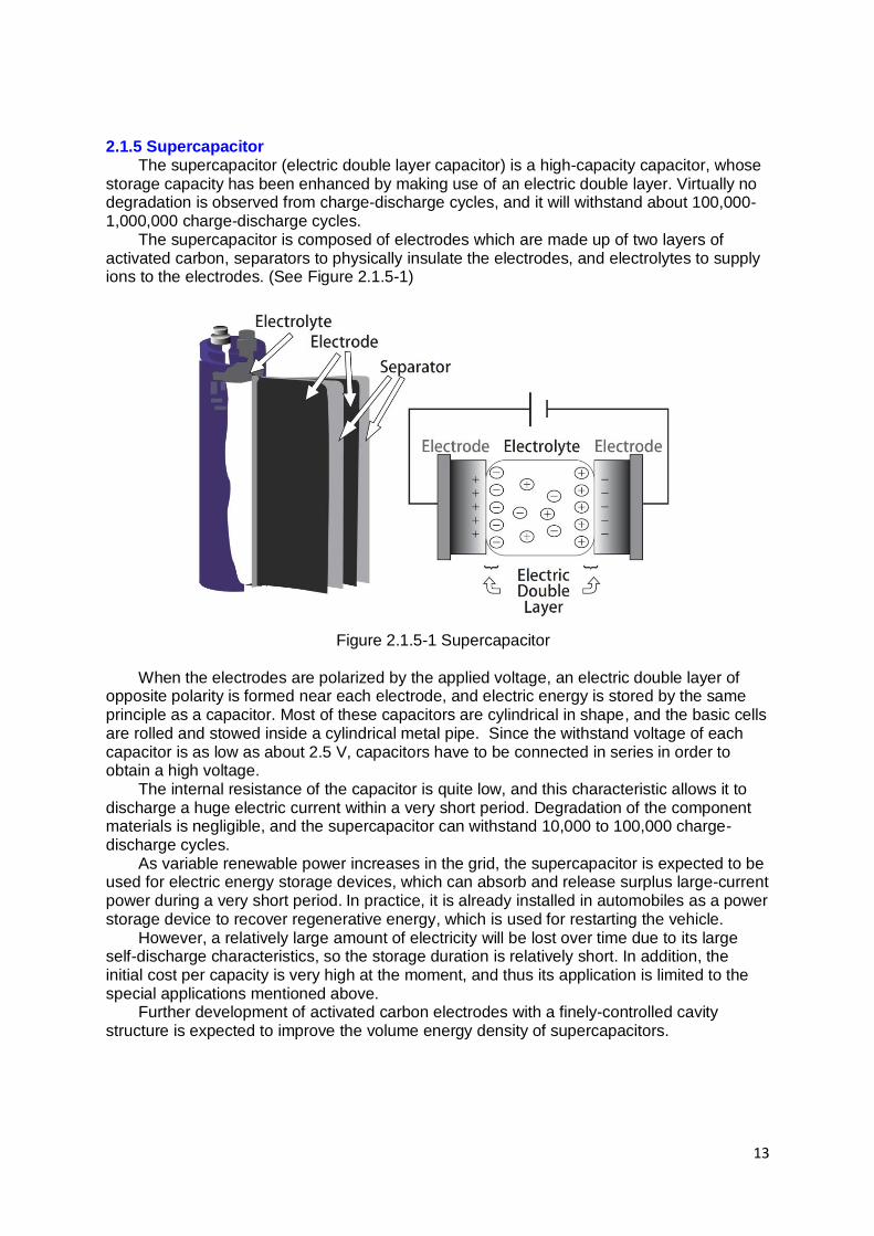
2.1.5 Supercapacitor The supercapacitor (electric double layer capacitor) is a high-capacity capacitor, whose
storage capacity has been enhanced by making use of an electric double layer. Virtually no degradation is observed from charge-discharge cycles, and it will withstand about 100,000-1,000,000 charge-discharge cycles.
The supercapacitor is composed of electrodes which are made up of two layers of activated carbon, separators to physically insulate the electrodes, and electrolytes to supply ions to the electrodes. (See Figure 2.1.5-1)
Figure 2.1.5-1 Supercapacitor
When the electrodes are polarized by the applied voltage, an electric double layer of opposite polarity is formed near each electrode, and electric energy is stored by the same principle as a capacitor. Most of these capacitors are cylindrical in shape, and the basic cells are rolled and stowed inside a cylindrical metal pipe. Since the withstand voltage of each capacitor is as low as about 2.5 V, capacitors have to be connected in series in order to obtain a high voltage.
The internal resistance of the capacitor is quite low, and this characteristic allows it to discharge a huge electric current within a very short period. Degradation of the component materials is negligible, and the supercapacitor can withstand 10,000 to 100,000 charge-discharge cycles.
As variable renewable power increases in the grid, the supercapacitor is expected to be used for electric energy storage devices, which can absorb and release surplus large-current power during a very short period. In practice, it is already installed in automobiles as a power storage device to recover regenerative energy, which is used for restarting the vehicle.
However, a relatively large amount of electricity will be lost over time due to its large self-discharge characteristics, so the storage duration is relatively short. In addition, the initial cost per capacity is very high at the moment, and thus its application is limited to the special applications mentioned above.
Further development of activated carbon electrodes with a finely-controlled cavity structure is expected to improve the volume energy density of supercapacitors.

14
2.1.6 Lead Acid Battery The lead acid battery is a rechargeable battery that uses lead dioxide for its cathode,
lead for its anode, and diluted sulfuric acid for its electrolyte. In the discharging process, the following reactions take place in both electrodes:
Cathode: PbO2 + 4H+ + SO42- + 2e- → PbSO4 + 2H2O
Anode: Pb + SO42- → PbSO4 + 2e-
Entire battery: PbO2 + 2H2SO4 + Pb → 2PbSO4 + 2H2O
Invented by Gaston Planté in 1859, the lead acid battery is a rechargeable battery with
the longest history for automobile applications. The nominal voltage of a single cell is relatively high at approximately 2 V. Stable performance is shown even if a large current is discharged within a short time, or if it is discharge slowly over a long time. Owing to its relatively low material cost, this storage battery has the largest production volume in the world. However, compared to other batteries, because it is lower energy density than other batteries, it is large and heavy. In addition, recycling of the battery materials is a prerequisite, as lead is harmful to the human body and the environment. Besides car batteries, the lead acid battery is also used for backup power applications and as the main power source for electric cars like forklifts and golf carts, etc.
There are some attempts to use this battery for stationary electric storage applications. By improving the electrode materials, some batteries show a high charge-discharge efficiency of over 87%, and a high cycle durability of over 4,500 cycles. However, compared to lithium ion and other batteries, its charge-discharge efficiency and energy density are still low, and further development is required.

15
2.1.7 Nickel-metal Hydride Battery The nickel-metal hydride battery has 2.5 times energy density of a nickel cadmium
battery, and it does not contain cadmium, which is harmful to the human body and the environment. Consequently, its use expanded rapidly after 1990.
Nickel is used for its cathode, metal hydride alloy or misch metal for its anode, and dense potassium hydroxide aqueous solution for its electrolyte. (See Figure 2.1.7-1)
Figure 2.1.7-1 Principle of Nickel-metal Hydride Battery In the discharging process, the following reactions take place.
Cathode: NiOOH + H2O + e- → Ni (OH) 2 + OH-
Anode: MH + OH- → M + H2O + e-
Entire battery: NiOOH + MH → Ni (OH) 2 + M
Due to its excellent discharge characteristics, coupled with the fact that it is relatively
safe under severe conditions, nickel-metal hydride batteries are installed in hybrid vehicles to recover the regenerative energy and to restart the vehicle from the idling-stop condition.
The battery capacity decreases gradually if the battery is charged before it is fully discharged. This phenomenon is called the “memory effect,” and the nickel-metal hydride battery has a slight “memory effect,” which is much milder than that of nickel cadmium batteries. There is also a risk of significant performance drop if it is over-discharged, and a risk of explosion if it is excessively over-charged. Therefore, it is important to control its
charge-discharge state properly during operation. In addition, its self-discharge rate is
relatively high. Some of these batteries also use rare earth metals like neodymium in the metal hydride
alloy. As a result, there are concerns that future costs might be higher and unstable.

16
2.1.8 Lithium Ion Battery The lithium ion battery uses lithium composite oxides such as lithium nickelate, lithium
cobaltite, and lithium manganite for its cathode, and carbon materials such as graphite for its anode. To support the exchange of lithium ions between the electrodes, the inside of the battery is filled with electrolyte made of organic solvent, such as ethylene carbonate, and lithium salts such as LiPF6 are dissolved in its electrolyte.
The lithium ion battery is the most advanced rechargeable battery owing to the recent diffusion of information & telecommunication devices such as mobile PCs and smartphones. Many types of material combinations are available, but the basic principle is the same. The charge reactions of the lithium ion battery using lithium cobaltite for its cathode are as follows.
Cathode: LiCoO2 → Li1-xCOO2 + xLi+ + xe
Anode : 6C + xLi+ + xe
- → C6Lix
Entire battery: LiCoO2 + 6C → Li1-xCOO2 + C6Lix
The principle of the lithium ion battery reaction is illustrated in Figure 2.1.8-1, and both
electrodes have stratified structures and allow lithium ions to accumulate inside the layers. When the lithium ion battery is charged, lithium ions transfer from the cathode to the anode through the electrolyte. In the discharging process, these lithium ions accumulated in the anode, return to the cathode, and the electrons move simultaneously in the opposite direction.
Figure 2.1.8-1 Principle of Lithium Ion Battery
The electrodes are partitioned by a separator so as not to make contact with each other.
This separator is made of polyethylene or polypropylene membrane with minute holes in it. A variety of advantages can be cited as features of lithium ion batteries, including 1)
high energy density, 2) high charge-discharge efficiency 3) small self-discharge rate 4) relatively high durability. In addition, the State of Charge (SOC) can be easily monitored from

17
the battery voltage. Therefore, the lithium ion battery is used extensively in many applications. However, the organic solvent containing a large amount of highly active lithium salts is
used in lithium ion batteries. If these organic solvents are overheated, vapors such as hydrogen gas etc. are produced and they may be ignited quite easily. In terms of safety, this battery has to be handled with care, so the voltage of each cell needs to be monitored and controlled carefully to avoid its over-charging and over-discharging.

18
2.1.9 Sodium Sulfur Battery (NaS Battery) The sodium sulfur battery (NaS battery) is a rechargeable battery, and the basic cell
configuration is illustrated in Figure 2.1.9-1. It uses molten sulfur for the cathode, molten sodium for the anode, and the two electrodes are separated by a solid electrolyte made of β-alumina.
Figure 2.1.9-1 NaS Battery Cell
In order to operate this battery, sulfur and sodium has to be maintained in the liquid state, and β-alumina electrolyte has to show high sodium-ion conductivity. Therefore, the battery operates at temperatures as high as approximately 300-350 deg C. The discharge reactions are as follows.
Cathode: 5S + 2Na+ + 2e
- → Na2S5
Anode: 2Na → 2Na+ + 2e
-
Entire battery: 2Na + 5S → Na2S
The energy density is approximately 3 times higher than that of the lead acid battery. As
the β-alumina electrolyte has almost no electrical conductivity, there is no self-discharge. The charge-discharge efficiency is also high and a durability of over 15 years can be expected due to the stability of its solid-state electrolyte.
However, the NaS battery requires heater power to maintain its temperature in case the utilization rate drops, and consequently the total system efficiency decreases substantially. It is thus suitable for applications, which require relatively longer term (e.g. 6-7 hours) charge-discharge duration. The NaS battery is considered one of the most promising candidates for high power grid-related applications, such as the peak shaving and the emergency power supply to compensate for momentary voltage drops.

19
2.1.10 Redox Flow Battery The redox flow battery is a rechargeable battery, in which energy is stored in two
soluble redox couples. As shown in Figure 2.1.10-1, it is composed of cell stacks, tanks to store the electrolyte, circulation pumps, and so on.
Figure 2.1.10-1 Redox Flow Battery
The most advanced types of flow batteries use the redox (reduction and oxidation)
reactions of vanadium (V), and the charge reactions are as follows. Cathode: V
4+ → V
5+ + e
-
Anode: V3+
+ e- → V
2+
Entire battery: V4+
+ V3+ → V
5+ + V
2+
In the charging process, tetravalent vanadium ions are oxidized into pentavalent vanadium ions in the cathode, and trivalent vanadium ions are reduced into divalent vanadium ions in the anode, and hydrogen ions move from the anode side to the cathode side through the separator to keep the electric neutrality of the aqueous solution.
The battery reaction is just a change in the valence of ions in an aqueous solution so the active substances do not deteriorate during cell reactions. The deterioration of cell materials is negligibly small by the charge-discharge cycles.
The power output of the redox flow battery is determined by the number of cells, while the storage capacity is determined by the volume of its electrolyte, or the size of the tanks. Therefore, it is possible to design the output and capacity independently, allowing a flexible design to meet the application requirements.
Initially, it was developed for large-scale power storage applications, such as the load leveling, the backup power supply, the peak-shaving, and the peak-shift, on account of its excellent cycle durability and safety. The redox flow battery can withstand irregular charge-discharge operations, and also shows the instantaneous response in the order of several milliseconds. In recent years, as a large amount of variable renewable power are deployed

20
in the grid, this battery technology is expected to contribute to the stability of power distribution systems.
However, motor power is consumed to circulate the electrolyte, and this lowers the overall charge-discharge efficiency. In addition, large tanks are required due to the limited solubility of vanadium salts, and its energy density is lower than that of the lithium ion battery. Vanadium is a fairly rare and expensive metal, so there are some attempts to use other metals, such as iron and chromium instead of vanadium. In order to reduce the battery cost, further development is required.

21
2.1.11 All-solid-state Battery Electrolyte in the lithium ion battery vaporizes easily when heated, and highly
combustible gases like hydrogen may be produced. Therefore, in terms of safety, extreme caution is required in operation.
The all-solid-state battery, which replaces this electrolyte with an inorganic solid-state electrolyte, is inherently safe. In addition, if solid-state electrolytes can be used, the cells can be easily laminated, and leads to increase their energy density. It is expected to show excellent durability against charge-discharge cycles, because the interfaces between the electrode and the electrolyte are very stable. Owing to its high level of safety, energy density, and durability, the all-solid-state battery is regarded as the ultimate battery.
There are two types of all-solid-state batteries; the thin film type and the bulk type. (See Figure 2.1.11-1)
Figure 2.1.11-1 All-solid-state Battery2
The thin film type all-solid-state battery has already been commercialized for
communication equipment and medical applications. It is manufactured by depositing a thin film onto the substrate. It has been verified that the all-solid-state battery suffers almost no capacity degradation even after 40,000 charge-discharge cycles, and therefore it has great potential.
However, for energy storage applications, large amounts of active substances have to be accommodated within the electrode layers so as to increase its capacity, and therefore, a bulk type all-solid-state battery has to be developed for these applications. As a result, there are still hurdles to be overcome in commercializing this technology. In particular, development of solid-state electrolytes with high ion conductivity is essential.
2 Source; Prof. Hayashi, Osaka Prefecture University

22
Solid-state electrolytes can be broadly divided into inorganic materials and polymer materials. Among inorganic materials, certain sulfides types have a similar ion conductivity of about 10-2 S/cm as conventional electrolyte solutions. The lithium-sulfur battery, one type of all-solid-state batteries, which use sulfur in the cathode and sulfides as the solid-state electrolyte, is now under development. However, the resistance at the interface between the solid-state electrolyte and the electrodes is still large, and further improvements are required. In addition, the humidity of the room has to be carefully controlled in the cell manufacturing processes, because hydrogen sulfide (H2S), a toxic and hazardous gas, is easily produced when sulfides react with water.
Development of solid oxide electrolytes is also making progress for inorganic types. Although the ion conductivity is still low at the 10-3 S/cm level compared to sulfides, a solid oxide electrolyte is highly expected to be developed, because it can be handled more easily. Development on solid polymer electrolytes has also been carried out very actively, as future mass production will be relatively easy and it can provide flexibility in the cell structure. However, the ion conductivity especially at low temperatures is still low and further improvements are required.
23
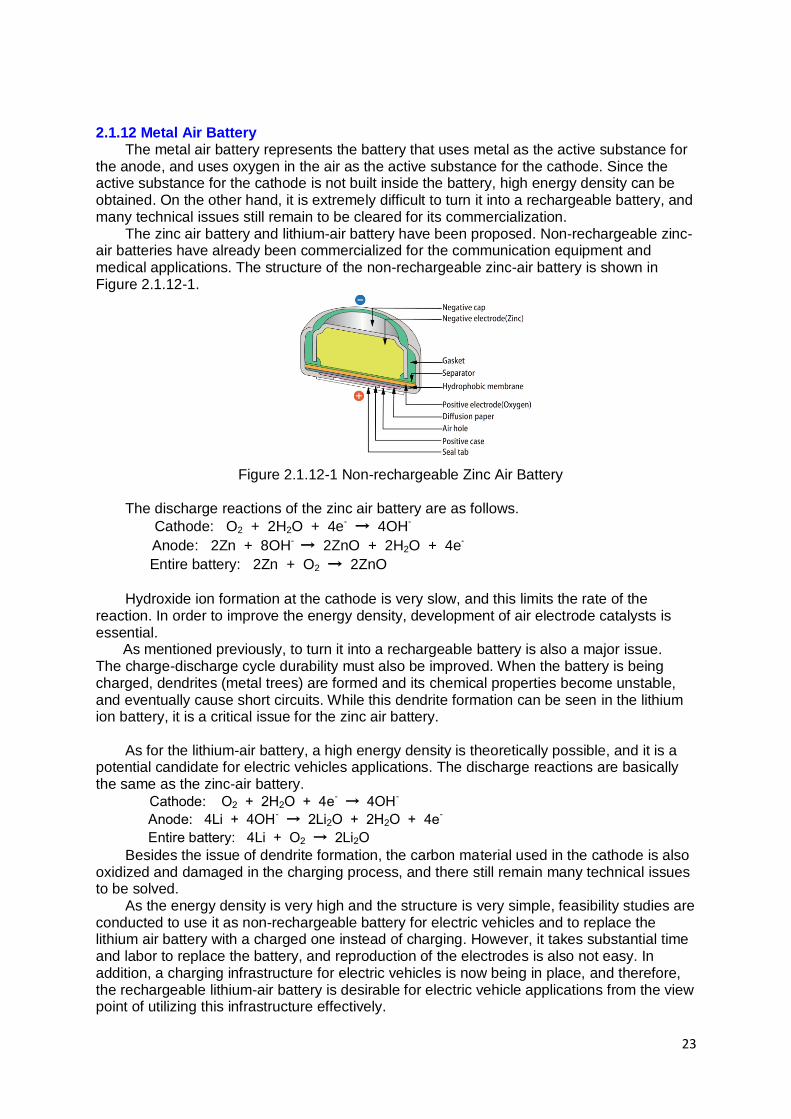
2.1.12 Metal Air Battery The metal air battery represents the battery that uses metal as the active substance for
the anode, and uses oxygen in the air as the active substance for the cathode. Since the active substance for the cathode is not built inside the battery, high energy density can be obtained. On the other hand, it is extremely difficult to turn it into a rechargeable battery, and many technical issues still remain to be cleared for its commercialization.
The zinc air battery and lithium-air battery have been proposed. Non-rechargeable zinc-air batteries have already been commercialized for the communication equipment and medical applications. The structure of the non-rechargeable zinc-air battery is shown in Figure 2.1.12-1.
Figure 2.1.12-1 Non-rechargeable Zinc Air Battery
The discharge reactions of the zinc air battery are as follows.
Cathode: O2 + 2H2O + 4e- → 4OH-
Anode: 2Zn + 8OH- → 2ZnO + 2H2O + 4e-
Entire battery: 2Zn + O2 → 2ZnO
Hydroxide ion formation at the cathode is very slow, and this limits the rate of the
reaction. In order to improve the energy density, development of air electrode catalysts is essential. As mentioned previously, to turn it into a rechargeable battery is also a major issue. The charge-discharge cycle durability must also be improved. When the battery is being charged, dendrites (metal trees) are formed and its chemical properties become unstable, and eventually cause short circuits. While this dendrite formation can be seen in the lithium ion battery, it is a critical issue for the zinc air battery.
As for the lithium-air battery, a high energy density is theoretically possible, and it is a potential candidate for electric vehicles applications. The discharge reactions are basically the same as the zinc-air battery.
Cathode: O2 + 2H2O + 4e- → 4OH
-
Anode: 4Li + 4OH- → 2Li2O + 2H2O + 4e
-
Entire battery: 4Li + O2 → 2Li2O
Besides the issue of dendrite formation, the carbon material used in the cathode is also oxidized and damaged in the charging process, and there still remain many technical issues to be solved.
As the energy density is very high and the structure is very simple, feasibility studies are conducted to use it as non-rechargeable battery for electric vehicles and to replace the lithium air battery with a charged one instead of charging. However, it takes substantial time and labor to replace the battery, and reproduction of the electrodes is also not easy. In addition, a charging infrastructure for electric vehicles is now being in place, and therefore, the rechargeable lithium-air battery is desirable for electric vehicle applications from the view point of utilizing this infrastructure effectively.

24
2.1.13 Power to X (X= Hydrogen, Gas etc.) Demonstration projects, which utilize the surplus power from renewable energy to
produce hydrogen through the electrolysis of water, and which inject hydrogen into existing natural gas pipelines, are being conducted mainly in Germany and other European countries.
To inject hydrogen into existing natural gas pipelines, the hydrogen level needs to be kept below 10%, so that the combustibility of the natural gas may not vary excessively. Therefore, some projects, which produce and inject methane into natural gas pipelines by making hydrogen react with CO2, are also underway, and other projects are verifying to produce the liquid fuel such as methanol from hydrogen and CO2.
In “Power to X” systems, gas and liquid fuel is synthesized from hydrogen, which is first produced by surplus electric power. Water electrolysis is the most commonly used technology to produce hydrogen from electricity, so water electrolyzer development is a key for Power to X. There are three types of the water electrolyzer: the alkali type, solid polymers type, and solid oxide type.
Alkali-type water electrolysis is the oldest and most commonly used technology, and an aqueous solution containing 20-30% potassium hydroxide is used for its electrolyte, and asbestos is often used for the separator. Nickel-based catalysts are used for the anode and iron-based catalysts are used for the cathode. Solid polymer type water electrolysis uses almost the same materials as solid polymer fuel cells. A perfluoroethylene sulfonic acid membrane is often used for the electrolyte, iridium-coated titanium catalysts for the anode, and platinum-coated titanium catalysts for the cathode. Since precious metals are used, the cell material cost used to be higher than that of alkalis types. However, the distance between the electrodes and between the electrolyte and the electrode can be very small for this type. As a result, due to the low ionic resistance between its electrodes, it can be operated at a very high current density. In addition, it can be operated simply by supplying de-ionized water. Recently, to reduce the membrane costs, a hydrocarbon-based membrane for this application is now under development.
On the other hand, a high temperature water electrolysis technology using the same materials as solid oxide fuel cells is also being studied. Yttria stabilized zirconia (YSZ) is used for the electrolyte, lanthanum strontium manganite (LSM) for the anode, and nickel cermet, the composite material of nickel, and YSZ for the cathode. During the electrolysis of water, as the temperature increases, the conversion efficiency becomes higher. As a result, if steam can be electrolyzed at a high temperature of about 700 deg C, it can be converted into hydrogen at a very high efficiency of over 90%. However, technical hurdles still remain.
In addition, projects to produce methane gas from hydrogen and CO2 are also underway in Germany and other Europeans countries.
The reaction to produce methane from hydrogen and CO2 is known as the Sabatier reaction.
CO2 + 4H2 → CH4 + 2H2O ΔH = -165 kJ/mol (exothermic reaction)
Demonstration plants are currently under construction in Germany.
The synthesis of methanol and hydrocarbon via CO is also being studied. CO is produced in the reverse shift reaction between CO2 and hydrogen as follows.
CO2 + 4H2 → CO + 2H2O ΔH = 41 kJ/mol (endothermic reaction)
Methanol synthesis reaction;
2H2 + CO → CH3OH ΔH = 91 kJ/mol (exothermic reaction)
Fischer-Tropsch synthesis reaction;
2H2 + CO → - (CH3) - + H2O ΔH = -167 kJ/mol (exothermic reaction)

25
If liquid fuels are produced by combining these reactions, storage and transportation of these fuels will be very convenient, and it subsequently allows effective use of the fuel in the required location.
As the share of renewable power such as wind turbines and PVs increases to the certain level, in some regions, the total renewable power will exceed the demand power, and renewable power will tend to be surplus constantly. Under these circumstances, to suppress the output of renewable power or the seasonal storage of surplus power will be required. These “Power to X” technologies are very effective for these applications.

26
2.2. Path to Innovation and Spread of Technologies
2.2.1 Current Status of Stationary Electric Energy Storage Technology The current status of the stationary electric energy storage technology is summarized in
Table 2.2.1-1. The capacity, cycle efficiency, energy density, initial system cost, technology maturity level and applicable charge-discharge time were reviewed from the available information. Table 2.2.1-1 Current Status of Stationary Electric Energy Storage Technology
Currently, about 96% of the installed storage capacity worldwide accounts for that of PSH (Pumped-Storage Hydropower). In order to deploy power storage system extensively, it is necessary for the initial installation costs to be reduced lower than that of PSH on either output base (kW) or storage capacity base (kWh). In this table, CAES (Compressed Air Energy Storage) looks less expensive than PSH. However, this cost is based on the case that can utilize the underground caverns for air storage. In the case where the air storage tanks are installed on the ground, further cost reduction is required to compete with PSH. Compared to CAES, LAES (Liquid Air Energy Storage) has an advantage in terms of future initial cost, because the capacity of the air storage tank can be much smaller. However, the system is still in the demonstration stage, the charge-discharge efficiency and system cost has to be evaluated in detail.
Considering the charge-discharge efficiency, Power to Hydrogen is relatively inefficient. The energy loss is about 20-45% in the water electrolysis and storage process, and about 45-60% in the power generation process from hydrogen via a fuel cell. However, as a means of long-term (in the order of days and months) power storage technologies, hydrogen will be a strong candidate.
The battery storage is much more promising because the cycle efficiency largely exceeds that of PSH, but further cost reductions and durability & reliability improvements are still required.
SMES (Superconducting Magnetic Energy Storage) and supercapacitor are promising technologies for relatively shorter term (in the order of milliseconds) power storage. Although the initial cost in terms of the storage capacity is extremely high, the capacitor has already been employed in automobiles for recovering regenerative energy.

27
The flywheel is also a technology used for storing electricity for a relatively short period. Because electric energy is stored by rotating energy, a longer lifetime is expected. However, further initial and maintenance cost reductions are required.
2.2.2 Policy Support and Institution for Stationary Electric Energy Storage Market Currently, there are few incentives to deploy stationary electric energy storage devices
for power producers and power consumers. Therefore, it has a significant meaning to actively promote deployment with support policies and institutions. Renewable power from photovoltaic cells and wind turbines is directly connected to the power grid, and power producers usually earn income based upon the total amount of power fed into the gird. In this case, the companies, which manage and guarantee the grid power quality, have to control the total amount of grid power according to a widely fluctuating power demand. These companies have to bear a large burden technically and financially, if they cannot recover the investment costs by increasing the power rate. However, for power producers, electric energy storage devices will be a large cost burden, so they will try to avoid these investments. Therefore, the following six measures will play important roles in deploying the stationary electric energy storage devices extensively: 1) financial Incentives, 2) diversification of the power transaction market, 3) research and development, 4) power storage mandate, 5) deregulation of grid connection guidelines, and 6) provision of safety related guidelines.
These public support and institutions are summarized in Table 2.2.2-1. Table 2.2.2-1 Stationary Electric Energy Storage Market: Public Support and Institution
1) Financial Incentives
For grid operators, subsidies for electric energy storage devices will be a great incentive, and they will facilitate investment for electric energy storage devices.
In Japan, the subsidy program commenced for residential customers to install electric energy storage devices in 2012. This program began after the devastating earthquake in 2011, primarily for energy security reason. At present, power from PVs is purchased under a FIT (Feed in Tariff) scheme, however, the purchase price from PVs is supposed to be substantially reduced in around 2020. Therefore, the battery subsidy program will be beneficial to residential customers, who have PVs on the roof of their house. 2) Diversification of the power transaction market

28
An ancillary service is an energy service that provides and guarantees power quality for customers with voltage and frequency control capabilities and instantaneous reserve power. In the USA and Europe, power transaction markets for this service actually exist.3 4 Electric power companies guarantee the power quality for customers, who are purchasing this service if necessary. In the USA, the average extra power tariff for the frequency control market was traded at about 1.8 cents/kWh, and that for the instantaneous reverse power was traded at about 1.1 cents/kWh in 2010. Some power producers provide this service, and there exist companies, which provide solely for this service. This ancillary service, especially for the frequency adjustment service requires frequent output power changes and charge-discharge switching. For these requirements, battery technologies have technological advantages over conventional power plants and PSH, and this service creates promising markets for battery technologies.
Arbitrage is the type of power transaction to sell electric power at a higher price during periods of high demand, and store low-priced power during periods of low demand. If power will be traded at a much more variable rate in each shorter segment, this type of transaction will be established in the future. However, future power rates are extremely difficult to predict, therefore, there are practical issues with companies facing difficulties in deciding investment plans for power storage. 3) Research and Development
Most storage technologies, such as batteries, flywheel and supercapacitor and SMES are still in the demonstration and development stages. It is quite important to support Research and Development activities for low cost and high performance power storage devices. In particular, battery technologies have been making rapid progress in recent years, and research and development for new materials has been conducted very energetically. 4) Power Storage Mandate
In 2013, the California Public Utility Commission approved the proposed mandate that three major electric power companies obliged to deploy 1.3 GW power storage facilities by 2020. The power producers in California are all investors-owned companies, so they had hesitated to invest in these storage facilities before this mandate was approved. Therefore, these regulatory requirements for power producers to install a set portion of power storage device will be very effective for grid power stability. 5) Deregulation of Grid Connection Guideline
The IEA (International Energy Agency) estimates huge amounts of electric vehicles over 28TWh will be deployed 2060 in 2DS (Two Degree Scenario). If some EVs are grid connected and their power can be utilized for surplus power absorption and for the emergency power output, grid power will be greatly stabilized. Therefore, the deregulation for the grid connection guidelines is desirable. 6) Provision of Safety related Guideline
The lithium ion batteries can be dangerous, if they are not operated appropriately. The lithium ion battery launched on the market only around 25 years ago, and its test protocol for safety tests has not been standardized yet. In order to facilitate development for these batteries, safety related guidelines have to be standardized as early as possible.
3 Source: Argonne National Laboratory, USA 4 Source: Organization for Cross-regional Coordination of Transmission Operators, Japan

29
2.3 Roadmap for Stationary Electric Energy Storage Technologies
Figure 2.3.0-1 shows one of the illustrative deliverables in the roadmap, representing the relationship between the variable renewable power share and storage requirements for power systems. In general, the discharge duration must be longer and the unit scale must be larger, as the variable renewable power share increases.
Figure 2.3.0-1 Variable Renewable Power (VRP) Share and Storage Requirements for Power Systems The each edge does not represent a specific technology, but appropriate technologies
will be selected, depending on technological progress and diffusion policies. There are also strategy alternatives, such as dispatchable power supply, curtailment of variable renewable power (VRP) output, demand-side adjustment, transmission network enhancement, consolidation of balancing areas, and energy carrier conversion. The order varies and depends upon technology readiness and region specific conditions, including power system design policies.
Figure 2.3.0-2 shows the roadmap for stationary electric energy storage technologies. PSH is the most widely deployed technology for energy storage, and recently variable-
speed pumped-storage hydropower systems have been developed and they are used for frequency stabilization and mitigation of grid power fluctuations. It normally takes 10 to 15 years to actually construct PSH from its planning stage. Therefore, it is important to utilize them efficiently and effectively with other power storage technologies.
CAES with ground air tanks has been demonstrated in Japan, and its operational data has been accumulated. This technology is a combination technology of proven equipment, but the heat management of the air compression process and adiabatic expansion process influence on the total system performance. Therefore, system optimization and cost reduction are required before its market diffusion in around 2025. Compared to CAES, the size of air storage tanks can be greatly reduced in LAES, so there is a potential for cost reductions in the future. However, the charge-discharge cycle efficiency has to be proven in a large-scale LAES system, and further system optimization is required. Market launch is expected in around 2030.
Elemental technologies for power to hydrogen have been already established and verified. Conversion efficiency from hydrogen to electricity is as low as 50-55% via fuel cells

30
and the round-trip efficiency is relatively low at present. However, as the share of VRP increases in the future, power to hydrogen will have a more significant meaning as a long term power storage technology in around 2030.
Hydrogen will be a strong candidate to store surplus VRP for more than weeks. Therefore, fuel cell vehicles will also play an important role as one of hydrogen applications, because they consume hydrogen directly. Power to X, (X= methane, or other fuels) projects are now under demonstration in Germany. Conversion to hydrogen is the initial step of Power to X.
Battery technologies are being demonstrated for large stationary applications, and their safety and efficiency have been verified. In particular, NaS and redox flow batteries are well demonstrated technology, and they can be utilized as a means of frequency control and peak shift applications.
However, to be used widely in many applications, further cost reductions are still required. Material development and system optimization are now actively underway. Next generation Lithium Ion batteries and others are also anticipated to realize before 2030.
In order to increase the battery efficiency, the power conditioning system (PCS) efficiency increase is also beneficial to improvement of battery system performance. New semiconductor substrates such as silicon carbide (SiC) and gallium nitride (GaN) will be developed in around 2030.
SMES systems have been demonstrated as a device that suppresses instantaneous voltage drops, but it has a problem with the cost of cooling the superconducting material. High-temperature superconducting wires are expected drastically to reduce the cost of cooling equipment in around 2030.
Flywheels are a verified technology, but maintenance cost reduction of bearings is a big challenge. Employing superconducting material for bearing could substantially reduce maintenance costs in around 2030. Supercapacitors are an established technology, and are used for regenerators in automobiles. For stationary applications, they are expected for short term storage device, which discharges power for 10 seconds to 1 minute. Development of much higher surface area carbon electrodes is expected before 2030.

31
Figure 2.3.0-2 Roadmap for Stationary Electric Energy Storage Technologies

32
3. Roadmap for Mobility Electric Energy Storage Technology
3.1 Technologies for Mobility Electric Energy Storage Conventional internal combustion engine (ICE) vehicles emit not only CO2 but also the
harmful substances, such as nitrogen oxides and PM2.5. In recent years, the fuel efficiency of ICE vehicles has been improved. However, only about 17%-21% of the fuel energy in a normal ICE vehicle can be used for running the vehicle.
On the other hand, electric vehicles do not emit hazardous gases during driving, and 59%-62% of the electrical energy can be used for running the vehicle.5 Therefore, the electrification of automobiles can reduce CO2 emissions drastically. In the future, further increases in the share of renewable energy will lead to greater CO2 emissions reductions.
3.1.1 Battery for Electric Vehicles At present, most Hybrid Electric vehicles (HEVs) and Plug-in Hybrid Electric Vehicles
(PHEVs) utilize 5-12 kWh battery per vehicle, while most EVs utilize 11-40 kWh battery. The driving range of an EV is around 120-400 km. This short driving range of the EV is one of disadvantage against the ICE type. Therefore, some EVs increase battery capacity to around 60kWh in order to extend the range to around 600 km. However, to increase battery capacity means an increase in the weight of the automobile, and fuel economy is somewhat scarified.
Although the nickel-metal hydride battery was employed in the first hybrid vehicle, released by Toyota Motors in 1997, most electric vehicles and plugin hybrid vehicles now employ lithium ion batteries for the following reasons: 1) High Energy Density
The fuel efficiency of electric vehicles becomes worse as the weight of the storage batteries increases. Therefore, the weight-based energy density is important. In addition, as the space for storage batteries is also limited, the volume-based energy density is also important. Compared to nickel cadmium and nickel-metal hydride batteries, the lithium ion battery has a higher energy density. 2) High Cycle Durability
Electric vehicles are frequently charged and discharged, so the cycle durability is quite important. Compared to other batteries, the lithium ion battery shows superior cycle characteristics. 3) No Memory Effects
Nickel cadmium and nickel-metal hydride batteries have a memory effect, which reduces the battery capacity gradually if the battery is charged before it is fully discharged. In the case of hybrid vehicles, this effect can be mitigated by designing them to be charged only after they have been fully discharged, but in the case of electric vehicles, it is quite difficult to control the charging-timing since the main power source is always coming from the battery. There is almost no memory effect with the lithium ion batteries, so they have an advantage over nickel-metal hydride batteries.
As the electric vehicle requires several hours to charge, its driving range is a very important factor. If the installed battery capacity is increased, the driving range can be increased. However, the weight of the vehicle will also increase by that amount, and it leads
5 Source: U.S. Department of Energy

33
to decrease its fuel efficiency. Therefore, the development of a high energy density battery is required. In order to extend the driving range, energy density improvements are desirable. Current energy density of HEVs and PHEVs is estimated around 70-80 Wh/kg, and for EVs this is around 100-150 Wh/kg on a battery cell weight basis.
In the current situation, the lithium ion battery looks advantageous, but higher energy density batteries, such as metal air batteries and next generation batteries, are expected to be developed.
In addition, in electric vehicles, battery safety should be ensured even in the event of an unexpected accident. Considering the safety requirements for batteries, the all-solid-state battery is the most desirable, and thus early commercialization is awaited.
According to IEA ETP2017, the IEA estimates 28 TWh electric vehicle batteries will be
deployed in 2060 in the two degree scenario. This electric energy storage capacity is extremely large, and if electric vehicles can be used to absorb surplus power and for emergency supplies, it will contribute immensely to the stability of the grid power system.
Demonstration projects utilizing electric vehicles for demand response applications are being conducted in many countries, and confirmation of their effectiveness is now underway.6
However, the frequent charge and discharge cycles will shorten the lifetime of EV batteries, so for these applications, it would be quite important to develop a total system control strategy to utilize EVs appropriately in the whole system.
6 Source: Southern California Edison Company

34
3.1.2 Electric Vehicle Charger In Japan, the power output of normal home chargers ( 200V AC type) is around 3kW, and
a 30-minute charge allows an EV to drive for approximately 10 km, and an 8-hour charge for approximately 160 km.
The fast charger uses 3-phase AC 200 V and has 50 kW power output, and this allows an EV to drive for approximately 80 km on a 15-minute charge. However, to install this 50 kW class fast charger, an additional initial investment is required in the electric equipment, including the transformer and other components, and results in high initial investment costs.
In order to suppress this initial investment costs, some fast chargers are equipped with storage batteries. For example, a fast charger has 50 kW power output for EVs, but 28 kW is covered by the normal low-voltage charging facility and the rest of the 22 kW is supplied by the storage batteries. When use of charging facilities is still relatively low in the early deployment stages, this contributes to reducing the total investment costs for the charging stations.
To accelerate the deployment of electric vehicles, it is essential to establish a charging infrastructure at the commercial facilities and office buildings. Electric vehicles are being politically promoted in China, the USA and Europe, and many fast chargers have been installed as well in those countries.
However, the inlet power specifications of chargers vary from country to country, and this makes it difficult for manufacturers to standardize the chargers and to reduce their manufacturing costs. In the EU, standards for normal chargers were proposed by Germany, and they have been adopted in all EU countries since January 2013. Specifications for the charger connector and the communication protocol between charger and EV, are standardized in these regions. However, a few standards still exist in the world. Further international standardization of these specifications is desirable and awaited.
There are some attempts to develop wireless charging from roads and at bus stops. If
wireless charging from roads becomes possible, the battery capacity of EVs will be greatly reduced. This will contribute to reducing the initial cost and weight of EV significantly. Wireless charging will be especially beneficial for electric buses and trucks, but they are in the demonstration stage, and still require further research and development .

35
3.2 Path to Innovation and Spread of Technologies
3.2.1 Current Status of Mobility Electric Energy Storage Technology The current status of mobility electric energy storage is summarized in Table 3.2.1-1.
Table 3.2.1-1 Current Status of Mobility Electric Energy Storage Technology
The first HEV was released by Toyota Motors in 1997, and a nickel-metal hydride battery was employed in this HEV. At present, most PHEVs and EVs employ lithium ion batteries as their main power storage device. Current HEVs and PHEVs utilize a 5-12 kWh battery and their driving range without ICE (Internal Combustion Engine) is around 25-68 km, while EVs use an 11-40 kWh battery giving a driving range of around 250-400 km. This short driving range is a disadvantage compared to the ICE type, so some EVs increase battery capacity to around 60kWh so as to secure around 600 km driving range. However, to increase the battery capacity means increasing the weight of the automobile, which sacrifices fuel economy. In order to extend the driving range, energy density improvements are desirable. Current energy density of HEVs and PHEVs is estimated at around 70-80 Wh/kg, and for EVs this is around 100-150 Wh/kg on a battery pack weight basis. Batteries mainly degrade their performance by charge-discharge cycles. However, the life of the battery depends upon the design concept of the EV. The life time of current battery is around 2,000-4,000 cycles for HEVs and PHEVs, and 500-1,000 cycles for EVs. Replacement costs of a battery pack are released by automakers publicly, but the actual battery cost is uncertain. According to many sources, the battery cost is estimated to be around 500-600 USD/kWh for HEVs and PHEVs, and around 300-400 USD/kWh for EVs.
3.2.2 Public Support and Institution for Mobility Electric Energy Storage Market In order to deploy the electric vehicles extensively, various public supports and
institutions are needed. Effective support policies are summarized in Table 3.2.2-1. Public support and institutions are set out for zero emission vehicles (ZEVs) in many countries, and they are effective not only for battery electric vehicles but also for fuel cell vehicles (FCVs).

36
Table 3.2.2-1 Mobility Electric Energy Storage Market: Public Support and Institution
1) Financial Incentives
Subsidies for ZEVs and the home chargers are highly effective. In the similar way, tax exemption and differentiated taxes for ZEVs are also effective. For differentiated taxation, automobile tax on ICEs, HVs, PHEVs, EVs and FCVs can be set according to their CO2 reduction amount.
In Norway, after an automobile acquisition tax and value added tax exemption were enacted, electric vehicles became widespread.
As for the home chargers for EVs and PHEVs, its installation cost is largely reduced if it is installed simultaneously when the house is newly built. Therefore, the home charger subsidy is especially effective for buyer of the new houses.
2)Policy for increasing the value position for ZEV
The Chinese government regulates the number of license plates to mitigate air pollution problems in urban areas. In these countries, if the government gives the privileged availability of license plate for ZEV owners, they are very effective.
In some European countries, access to urban areas is restricted to reduce traffic congestion. In these countries, the privileged granting of access rights to ZEV owners will be also effective. Exemption from usage fees for road networks and the dedicated parking for ZEVs is also effective. Public available charging infrastructure is also one of supportive measures.
3)Research and Development
Electric vehicles are already commercially available, but the cost reduction of batteries is necessary. In addition, the battery performances, such as safety, energy density are also to be improved, and further deployment is required.
As for safety of automobile, the current lithium ion battery can be dangerous under severe conditions. Therefore, it is important to accelerate research and development for the next generation battery.
4)ZEV mandates
In California, USA as the regulatory requirements, automakers are required to sell a set portion of ZEVs, and it contributed to market diffusion of ZEVs. This mandate will be quite effective for automakers to accelerate ZEV development.
5) ZEV Procurement for Public Transportation

37
In the early commercial stages, it can be supportive measures that government purchases ZEVs for municipal cars, service vehicles and public transportation, including garbage vehicles and buses. This will consequently facilitate the deployment of a charging infrastructure.
6)Availability of Charging Infrastructure
A charging infrastructure of EVs is a prerequisite for their deployment. Especially, fast chargers at the commercial facility and office buildings must be deployed sooner. In the future, grid connected EVs would play more important roles to absorb surplus electric power and to supply power under tight power conditions, as their VRP share increases.
7)Provision of Safety related Guideline
The lithium ion battery has a risk of catching fire and smoking, if it is not operated properly. The safety of automobile batteries has to be tested in advance under the various severe conditions, including high and low temperatures and physical impact. At present, battery safety test protocols have not been standardized, and the standardization of a test protocol and safety guidelines is currently underway.

38
3.3 Roadmap for Mobility Electric Energy Storage Technology At present, the lithium ion battery is commonly used in EVs, but the emergence of metal
air and all-solid-state batteries are highly anticipated, on account of their high energy density and safety.
Automobiles can be involved in unexpected accidents, for this reason much safer batteries than the conventional lithium ion batteries are desirable.
The roadmap for mobility electric energy storage technologies is summarized in Figure 3.3.0-1.
Figure 3.3.0-1 Roadmap for Mobility Electric Energy Storage Technologies
In 2020, the energy density is targeted to be improved to 250 Wh/kg for PHEVs and
EVs, while battery costs will be reduced to 180 USD/kwh or less. In order to deploy EVs more extensively in the future, the energy density and battery costs have to be improved further. Future targets for the energy density and battery costs have been set at 500 Wh/kg, and less than 90 USD/kWh in 2030 by NEDO, and battery costs are expected to be less than 45 USD/kWh in around 2040. If this energy density target is achieved, driving range is estimated to extend to around 500km in 2030 with the current EV efficiency.
In order to achieve these targets, further research and development is required. As for the lithium ion battery, further cell material development and its cell design optimization will improve the energy density and will reduce battery costs in 2025. At present, some companies have manufactured EVs on a large production scale, but new manufacturing processes for mass production are anticipated to lower battery costs. Post Lithium Ion batteries, such as all-solid-state lithium batteries and metal air batteries are expected to take place in around 2030. For safety and energy density reasons, research and development of all-solid-state lithium batteries is actively underway, but they are still in the fundamental research stage. Cell material development and cell optimization are required before market entry in around 2030.

39
Metal air batteries, including zinc air, lithium air and magnesium air, have been proposed and are under development. Their cell designs as primarily batteries are fairly simple and their energy densities are relatively high and attractive, but the cell designs have to be changed for rechargeable batteries. It will require a longer time until around 2030, before these batteries actually appear in the commercial market. PCS development contributes to improving the conversion efficiency and subsequently to extending the driving range. Post silicon semiconductor substrates, including Silicon Carbide (SiC) and Gallium Nitride (GaN) are expected to emerge in around 2030.

40
4. Roadmap for Stationary Thermal Energy Storage Technology
4.1 Technologies for Stationary Thermal Energy Storage Heat accounts for more than 50% of final energy consumption in the world.7 In the
colder regions, urban cities use 60% fossil fuels for heating building and residential space. Therefore, it is quite important to utilize solar heat and waste heat from CHP (Combined Heat and Power) system and power plants, from the view point of saving energy and reducing CO2 emissions. For developing countries, thermal heat storage (100-250 deg C) is also desired for the following reasons; 1) high cost of importing fossil fuels and 2) poor efficiency of appliances, and 3) smoke-inhalation using wood and charcoal for domestic cooking and heating in rural areas.8
Thermal energy storage can be categorized in two types; 1) heat is once stored as thermal energy, and then it is converted into electric energy and 2) heat is stored as thermal energy and it is used as thermal energy. The former example is CSP (Concentrating Solar Power) and the latter examples are district heating & cooling and underground thermal storage. Heat cannot be transferred as easily as electric power; therefore, the demand site has to be geographically adjacent to the supply site.
Many types of thermal storage technologies have been proposed and research and development activities are now underway. However, most technologies for low temperature heat utilization are not feasible in practice, because the running merits are too small to recover their initial investments, when considering the heat loss and power consumption to transmit heat. As a result, low temperature heat is not being recovered completely and is wasted in many cases.
4.1.1 District Heating & Cooling
In European countries, the demand for hot water from the heating and hot water supply is relatively large, and district heating systems are widely deployed. In particular, in Northern European countries like Sweden and Denmark, district heating systems supply over 40 % of the total residential heat demand. In these countries, hot water is recovered from the waste heat from CHP (Combined Heat and Power) systems, incineration plants, and biomass power plants, and supplied to households through hot water pipes.
The penetration rate in other European countries, like Germany, France, and England, is still not so high, and in many cases, natural gas boilers are used as a heat source. However, these countries are trying to deploy district heating systems.
In the USA, district heating systems started in the late 19th century, and unlike Europe, efforts were mainly led by the private sector.9 Initially, district heating systems were supplied mainly using the waste heat from power plants, but then the waste heat from the industrial plants and CHP systems. In urban areas, the cooling demand is increasing, and district cooling systems using a heat pump have also been deployed.
In Japan, the climate is warmer compared to northern Europe, and the heat demand is relatively small. If the quantity of heat supplied is small in district heating systems, the total amount of heat losses from the piping cannot be ignored, and in some cases, it would be difficult to secure the sufficient running merits and a total efficiency advantage. For private sector projects, the heat demand density has to be taken into account as well. On the other hand, the cooling demand is fairly large in summer, and use of district cooling systems has been increasing for commercial and office buildings. Deployment of ice storage air condition system is progressing in Japan and the USA.
7 Source: Energy Technology Perspectives 2017 by International Energy Agency 8 Source: Mr. Ravi Seethapathy, Biosirus Inc. 9 Source: Presentation material in the Fifth METI’s Thermal Energy Utilization Task Force Report on “Overseas District Heating System” in June, 2011

41
The ice storage is a form of latent heat storage. In this system, ice is made by electric heat pumps during the night, and stored in an artificial pool or special container in the building, and then used for cooling buildings during the day. In this system, the latent heat of ice can be used, so the space utilization is very high compared to cold water storage. In warmer climate regions, most of the electric power demand in summer is for air conditioning, so this ice storage is extremely effective for peak shaving and load leveling purposes. Recently in tropical countries, the electric power demand for cooling is increasing rapidly. Ice storage is a matured technology, but it will play an important role in many countries.
4.1.2 Underground Thermal Energy Storage In general, the underground temperature 10m below the ground surface is constantly
maintained at almost the same temperature throughout the year, regardless of outside temperature fluctuations. Many projects are underway to utilize this heat source. Underground Thermal Energy Storage (UTES) systems use the ground as a thermal storage medium to actively store unused hot heat and cold heat in the ground.
Three types of underground thermal energy storage technologies are available: Aquifer Thermal Energy Storage (ATES), Borehole Thermal Energy Storage (BTES), Pit Thermal Energy Storage (PTES). These technologies are actively deployed in Europe.
ATES technology is shown in Figure 4.1.2-1. Underground water is pumped up from one part of the aquifer and used for air-conditioning in summer. Then this used water is pumped back into another part of the aquifer, and stores waste heat there. In winter, operation is switched and this waste heat is used as a heat source for hot water, and this time cold heat is stored for summer. Thus ATES is used for long-term (seasonal) thermal energy storage applications.
Figure 4.1.2-1 Aquifer Thermal Energy Storage
After the first ATES plant commenced operation in the Netherlands in the 1980s, this fairly matured technology spread to countries including Sweden, Belgium, Germany, and

42
Denmark. As underground water is used in the ATES system, dissolved minerals may be deposited if the temperature difference is too large. Therefore, this system often operates at low temperature below 25 deg C, and consequently the allowable temperature difference is extremely small in the range of 10-12 deg C.
Not only contributing to energy conservation and reductions of CO2 emissions, but it also helps to reduce the amount of heat released into the atmosphere, while air-conditioning is being operated in summer, and thus it can be expected to mitigate the “heat island phenomenon”.
In case where the heat of the underground water is used indirectly, the impact on the environment is relatively limited, but in case where underground water is pumped up and injected back again, extra care needs to be taken to ensure that it does not affect other underground water sources. In countries like Denmark there are regulations specifying that the temperature of the water returned to the aquifer must not exceed 25 deg C, and that the monthly-averaged temperature must be below 20 deg C.
As for ATES, there is one risk that the government approval may not be given, and another risk that an aquifer large enough cannot be found even after preparatory underground surveys. ATES is widespread in the Netherlands, because there are many available aquifers, and the probability of finding a usable aquifer is very high.
As shown in Figure 4.1.2-2, BTES technology stores and uses underground heat in the
borehole. By digging a borehole to the depth of 30-100m and then inserting one or two heat exchanger pipes into it. The thermal enhanced grouting materials are poured into the borehole to increase the heat storage capacity. BTES technology usually uses a closed loop of water, so the impact on the environment is smaller than with ATES.
Figure 4.1.2-2 Borehole Thermal Energy Storage
Examples using underground heat are increasing rapidly in countries like the USA,
Germany, Sweden, Switzerland, Denmark, China, and Japan. However, there are few examples of active use of BTES for seasonal heat storage, and demonstration plants are operating in Germany, Sweden, and Denmark.
In future, if the effectiveness is verified, the use of underground heat may become much more popular.
Pit storage technology is a matured technology, and normally uses shallow insulated pits, in which hot water and cold water are stored and used for heating or cooling. In

43
Denmark, new pit storage projects are underway. A gigantic artificial pool is dug underground, and hot water, which is made from solar heat and heat from surplus renewable power is stored in the pit. The bottom of pit is covered with a huge plastic sheet to prevent the hot water from penetrating outside the pit. The surface of hot water is also covered with a similar plastic sheet and floating insulating lid. Figure 4.1.2-3 shows a picture of one of pit storage sites at Vojens, Denmark.
Figure 4.1.2-3 Picture of Pit Storage at Vojens, Denmark10
In the pit storage project at Dronninglund, Denmark, 62,000 m3 of hot water can be
stored, and the maximum storage temperature is at around 90 degree C, and over 90% of yearly storage efficiency is verified.10 From the investigations from similar pit storage projects, it is found that smaller heat loss and lower specific cost can be obtained as the size of pit increases.
10 Source: Dr. Furbo, Technical University of Denmark

44
4.2. Path to Innovation and Spread of Technologies
4.2.1 Current Status of Stationary Thermal Energy Storage Technology Table 4.2.1-1 shows the current status of stationary thermal energy storage
technologies. Table 4.2.1-1 Current Status of Stationary Thermal Energy Storage Technologies
Ice storage is in practical use in Japan and the USA. In summer, the energy demand for air conditioning occupies a large amount of the power demand for office and commercial buildings. In order to decrease the peak demand, stored ice which is produced with heat pump technology during the night, will be used for cooling during the day. It plays an important role in peak shift and peak cut of power demand for buildings.
Pit storage and underground storage for district heating is actively deployed in Denmark. Solar heat and waste heat from incineration plants and CHPs are once stored in an artificial pond underground, and then utilized for district heating.
However, the feasibility of district heating systems depends upon the density of hot water demand. In cold climate regions, the district heating system tends to be feasible, because of large hot water demand. In other regions, the heat loss from hot water pipes is relatively large, and the low demand for hot water in each house makes it difficult to recover the system installation costs.
Molten salt is one of the thermal energy storage technologies and some molten salts are practically used in CSPs. Phase change molten salts can store a much larger amount of heat, and its application for CSPs is expected.
High heat capacity thermochemical materials are expected to reduce the storage tank volume. However, not only heat capacity but also the thermal conductivity is a key factor in designing heat exchangers. Thermal storage materials with a high heat capacity, high thermal conductivity and low cost are required.

45
4.2.2 Policy Support and Institution for Stationary Electric Energy Storage Market
Public support and institution are summarized in Table 4.2.2-1. Table 4.2.2-1 Public Support and Institution for Stationary Thermal Energy Storage Market
District heating & cooling systems, including ice storage are well established
technologies. Therefore, subsidies for thermal storage devices will promote to deploy these technologies.
Most thermal energy storage technologies, such as ice storage, pit storage,
underground storage, and district heating are matured technologies. However, molten salts for high temperature applications are expected to improve the system performance of concentrating solar powers and wind heat generations.
Low temperature heat below 90 deg C is regarded as low quality energy, and some of
them are discarded and wasted. If districting heating systems could use this waste heat, it would have a significant effect on saving energy and reducing CO2 emissions.
If low grade heat from CHP systems, incineration plants, industrial plants, geothermal and solar, is recovered and utilized further for heating and hot water supply, huge amounts of energy can be saved especially in cold climate regions.
In Sweden, district heating systems are widespread, because these projects were first conducted by municipal government. Involvement of government is desirable for district heating system deployment in the early deployment stage.
4.3 Roadmap for Stationary Thermal Energy Storage Technologies The roadmap for stationary thermal storage technologies is summarized in Figure 4.3.0-
1. Ice storage is a viable technology option for distributed thermal storage in many
countries, therefore, market diffusion support, including subsidies is very effective to accelerate its deployment.
As for pit storage, many projects are under demonstration in Denmark. It is obvious that it would be effective for energy conservation and CO2 emission reductions, if it utilizes the waste heat from CHPs, incineration plants, industrial plants and solar heat. However, if they are not financially feasible, this technology will not be deployed extensively. Detailed evaluation of pit storage is awaited.
Evaluation of underground storage technology for long term thermal storage is also awaited. However, the temperature 10m below the surface is constantly maintained at almost the same temperature throughout the year, and there are many projects underway simply to use this underground heat in many countries. Accumulation of these underground thermal storage technologies will clarify the thermal storage capability and feasibility, and will accelerate its deployment in around 2020.
Molten salts of a mixture of sodium nitrate and potassium nitrate have already been utilized for CSP. Development of a phase change molten salt at around 600 deg C is

46
expected for CSP. This material can be also applied to wind heat power generation. Phase change molten salts will be developed in around 2030.
Thermochemical technologies, especially PCMs (Phase Change Materials) have the potential to reduce the size of hot water storage tank substantially. However, for practical use, total system costs of PCMs and heat exchangers have to be less expensive than conventional hot water storage tank systems. Most of these technologies are still in the fundamental research stage, and market launch is expected in around 2035.
Figure 4.3.0-1 Roadmap for Stationary Thermal Energy Storage Technologies

47
5. Proposal Creating new energy markets for stationary electric energy storage technology deployment
The stationary electric energy storage technology is an enabling technology for a large share of variable renewable power. Therefore, these technologies should be designed in the flexibility technology portfolio. However, in order to recover the investment cost for energy storage, new energy markets for e.g. ancillary services, have to be created. In addition, public supports and institution are also essential. Developing high energy density batteries and wireless charging for electric vehicles deployment
The mobility electric energy storage technology is an enabling technology for transportation electrification. It can work as stationary storage via a grid connection. Technical Issues still remain with wireless charging, and further development to increase the energy density is required. Promoting stationary thermal energy storage to utilize the renewable-based or environmental heat
The stationary thermal energy storage can store renewable-based or environmental heat. The market differs by region, and the heat demand and heat demand space density depends upon the climate in those regions.
Transparent approaches via roadmap sharing among global regions will bring huge
benefits through good practices and capacity building by stakeholders.

48
6. References
[1] IEA, "Technology Roadmap Energy Storage," 3 2014. [Online]. Available: https://www.iea.org/publications/freepublications/publication/TechnologyRoadmapEnergystorage.pdf#search=%27Technology+Roadmap+Energy+Storage+IEA%27.
[2] IEA, "Technology Roadmap Electric and plug-in hybrid electric vehicles," 6 2011. [Online]. Available: http://www.iea.org/publications/freepublications/publication/EV_PHEV_Roadmap.pdf.
[3] IRENA, "Renewables and Electricity Storage," 6 2015. [Online]. Available: https://www.irena.org/DocumentDownloads/Publications/IRENA_REmap_Electricity_Storage_2015.pdf#search=%27Renewables+and+Electricity+Storage+IRENA%27.
[4] METI, "Energy Related Technology Roadmap (in Japanese)," 8 2013. [Online]. Available: http://www.enecho.meti.go.jp/category/others/for_energy_technology/pdf/141203_roadmap.pdf#search=%27%E3%82%A8%E3%83%8D%E3%83%AB%E3%82%AE%E3%83%BC%E9%96%A2%E9%80%A3%E6%8A%80%E8%A1%93%E3%83%AD%E3%83%BC%E3%83%89%E3%83%9E%E3%83%83%E3%83%97+%E7%B5%8C%E6%B8%88%.
[5] NEDO, "Battery Roadmap2013 (in Japanese)," 8 2013. [Online]. Available: http://www.nedo.go.jp/content/100535728.pdf#search=%27%E8%93%84%E9%9B%BB%E6%B1%A0%E3%83%AD%E3%83%BC%E3%83%89%E3%83%9E%E3%83%83%E3%83%97+NEDO%27.
[6] CAO, "NESTI 2050," 9 2017. [Online]. Available: http://www8.cao.go.jp/cstp/nesti/suishin/nestiroadmap.pdf.
[7] C. ISO, "Advancing and Maximizing the Value of Energy Storage Technology," 12 2014. [Online]. Available: https://www.caiso.com/Documents/Advancing-MaximizingValueofEnergyStorageTechnology_CaliforniaRoadmap.pdf.
[8] US Drive, DOE, "Electrochemical Energy Storage Technical Team Roadmap," 6 2013. [Online]. Available: https://energy.gov/sites/prod/files/2014/02/f8/eestt_roadmap_june2013.pdf.
[9] DOE USA, "Energy Storage Roadmap for New York’s Electric Grid," 1 2016. [Online]. Available: https://www.ny-best.org/sites/default/files/type-page/39090/attachments/NY-BEST%20Roadmap_2016_finalspreads.c.pdf.
[10] EASE/EERA, "European Energy Storage Technology Development Roadmap towards 2030," 2013. [Online]. Available: https://www.eera-set.eu/wp-content/uploads/148885-EASE-recommendations-Roadmap-04.pdf.
[11] EASE/EERA, "European Energy Storage Technology Development Roadmap 2017 Update," 2017. [Online]. Available: http://www.eui.eu/Projects/THINK/Documents/Thinktopic/THINKTopic72012.pdf.
[12] D. M. B. O. P. M. B. L. H. D. Connolly, "Heat Roadmap Europe 2050," 10 2013. [Online]. Available: https://www.ecofys.com/en/publication/heat-roadmap-europe-2050/.
[13] F. I. f. S. a. I. R. ISI, "Technology Roadmap Energy Storage for Electric Mobility 2030," 4 2015. [Online]. Available: http://www.isi.fraunhofer.de/isi-wAssets/docs/t/de/publikationen/TRM-LIB2030.pdf.
[14] K. N. B.V., "Energy Storage Roadmap NL 2030," 4 2015. [Online]. Available: https://www.dnvgl.com/news/dnv-gl-berenschot-and-tu-delft-present-energy-storage-roadmap-in-the-netherlands-for-topsector-energie-22785.
[15] EUDP and D. E. Agency, "Status and recommendations for RD&D on energy storage technologies in a Danish context," 2 2014. [Online]. Available: https://ens.dk/sites/ens.dk/files/Forskning_og_udvikling/status_and_recommendations_for_rdd_on_energy_storage_technologies_in_a_danish_context_feb_2014.pdf#search=%27Status+and+recommendations+for+RD%26D+on+energy+storage+technologies+in+a+Danish+context%.

49
[16] SEAI and S. E. A. o. Ireland, "Electric Vehicles Roadmap," 8 2017. [Online]. Available: https://www.seai.ie/resources/publications/Electric-Vehicle-Roadmap.pdf#search=%27Electric+Vehicles+Roadmap%27.
[17] A. Clean Energy Council, "Australian Energy Storage Roadmap," 4 2015. [Online]. Available: http://www.cleanenergycouncil.org.au/cec/policy-advocacy/storage-roadmap.