= T'AND DF G CHARACTERISTICS AUTOGIRO DETERMINED iGHT
16
=_T'AND DF_G _CHARACTERISTICS AUTOGIRO - DETERMINED _ _iGHT __-_ ": _PRODUCIDBY NATIONAL TECHNICAL INFORMATION SERVICE U.S. DEPARIM[NT OF COMM[RCE SPRINGFIELO, Vk. 22161 !
Transcript of = T'AND DF G CHARACTERISTICS AUTOGIRO DETERMINED iGHT
=_T'AND DF_G _CHARACTERISTICS
AUTOGIRO -
DETERMINED _ _iGHT __-_ " :
_PRODUCIDBY
NATIONAL TECHNICALINFORMATION SERVICE
U.S. DEPARIM[NT OF COMM[RCE
SPRINGFIELO, Vk. 22161
!
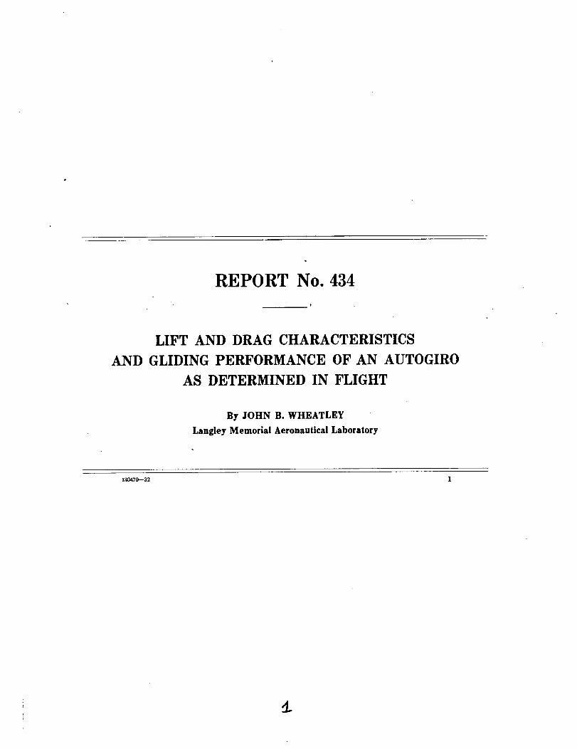
REPORT No. 434
LIFT AND DRAG CHARACTERISTICS
AND GLIDING PERFORMANCE OF AN AUTOGIRO
AS DETERMINED IN FLIGHT
By JOHN B. WHEATLEY
Langley Memorial Aeronautical Laboratory
130470-32 1
NATIONAL ADVISORY COMMITTEE FOR AERONAUTICS
NAVY BUILDING, WASHINGTON, D. C.
(AnindolzmdentGovernmentestablishment, createdbyact ofCongressapprovedMarch3,1915,for thesupervisionanddiractlonof the scientificstudy of the problemsof flight. Its memhership was ln_ to 15 by act approved March2, 1929(Public, No. g08,70th Congre_). It consistsof members who areappointed by the President,all of whom _erve a8such without compensation.)
JOSEPH S. AMES, Ph. D., Chairman,President, Johns Hopkins University, Baltimore, Md.
DAVID W. TAYLOR, D. Eng., Vice Chairman,Washington, D. C.
CHARLES G. ABBOT, SC. D.,Secretary, Smithsonian Institution, Washington, D. C.
GEORGE K. BURaESS, Sc. D.,Director, Bureau of Standards, Washington, D. C.
AhTHUR B. CooK, Captain, United States Navy,
Assistant Chief, Bureau of Aeronautics, Navy Department, Washington, D. C.WILLIAM F. DURAND, Ph.D.,
Professor Emeritus of Mechanical Engineering, Stanford University, California.BENJAMIN D. FOULOIS, Major General, United States Army,
Chief of Air Corps, War Department, Washington, D. C.HARRY F. GUGGENHEIM, M. A.,
The American Ambassador, Habana, Cuba.CHARLES A. LINDBERGH, LL. D.,
New York City.WILLIAM P. MAcCRAcKEN, Jr., Ph. B.,
Washington, D. C.CHARLES F. MARVIN, M. E.,
Chief, United States Weather Bureau, Washington, D. C.WILLIAM A. MOFFETT, Rear Admiral, United States Navy,
Chief, Bureau of Aeronautics, Navy Department, Washington, D. C.HENRY C. PRATT, Brigadier General, United States Army,
Chief, Materiel Division, Air Corps, Wright Field, Dayton, Ohio.EDWARD P. WARNER, M.S.,
Editor "Aviation," New York City.ORVILLE WRIGHT, So. D.,
Dayton, Ohio.
GEORGE W. LEWIS, Diredor of Aeronautical Research.
JOHN F. VICTORY, ,_eeretary.HER,ray J. E. P_ID, Engineer in Charge, Langley Memorial Aeronautical Laboratory, Langley Field. V_.
JOHN J. IDE, Technical Assistant in Europe, Paris, Francs.
CHARLES G. ABBOT.GEORGE K. BURGESS.ARTHUR B. COOK.BENJAMIN D. FOULOIS.CHARLES A. LINDBERGH.
WILLIAM P. MACCRACKEN, Jr.
EXECUTIVE COMMITTEE
JOSEPH S. AMES, Chairman.
DAVID W. TAYLOR, Vice Chairman.
CHARLES F. MARVIN.WILLIAM A. MOFFETT.HENRY C. PRATT.EDWARD P. WARNER.
ORVILLE WRIORT.
JOHN F. VICTORY, Seeretary.
REPORT No. 434
LIFT AND DRAG CHARACTERISTICS AND GLIDING PERFORMANCE OF AN
AUTOGIRO AS DETERMINED IN FLIGHT
By JOHN B. WHEATLEY
SUMMARY
The results of flight tests made by the National Ad-
visory Committee for Aeronautics on a Pitcairn " PCA-2"
autogiro are presented in this report. Lift and drag
coe_cisnts with the propeller stopped have been deter-
mined over approximately a 90 ° range of angles of attack.
Based on the sum of fixed-wing and swept-disk areas,
the maximum lift coe fwient is 0.895, the minimum drag
coe_cient with propeller stopped is 0.015, and the maxi-
mum LID with propeller stopped is 4.8. Lift coe f_cients
were found also with the propeller delivering positive
thrust and did not differ consistently from those found
with propeller stopped. Curves o.f gliding performance
included in this report show a minimum vertical velocigy
of 15feet per second at an air speed of 36 miles per hour
and a flight-path angle of --17 °. In vertical descent the
vertical velocity is 35 feet per second.
INTRODUCTION
Research on the autogiro has been undertaken by
the National Advisory Committee for Aeronautics in
connection with the study of the general problem of
safety in flight. The essential characteristic of the
autogiro that distinguishes it from conventional air-
planes is that the velocity of the lifting surfaces with
respect to the air is almost entirely independent of the
velocity of the machine as a whole. The value of this
attribute with respect to safety lies in the increase in
the useful range of air speeds at which flight may be
maintained.
The. determination of lift and drag characteristics
was decided upon as the initial step into an extensive
program of research because of the lack of reliable
full-scale information on the fundamental aero-
dynamic characteristics of the autogiro and the need
to establish clearly a datum to which further work willbe referred. The curves and data contained in the
body of this report constitute, so far as is known, the
first authentic full-scale information concerning auto-
giro characteristics that has been published. This re-
port presents the results of a series of glide tests, made
to determine the lift and drag characteristics of a
Piteairn PCA-2 autogiro over the full range of angles
of attack. The tests were performed by the National
Advisory Committee for Aeronautics at Langley
Field, Va.
APPARATUS AND METHODS
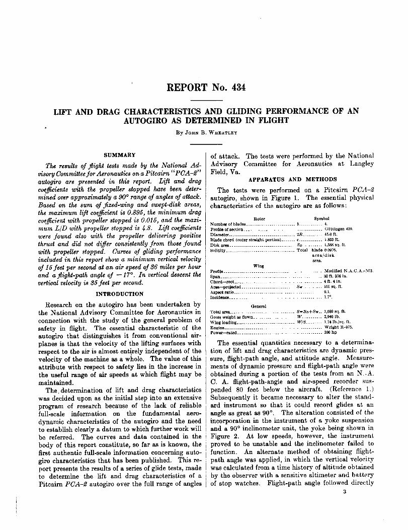
The tests were performed on a Pitcairn PCA-2
autogiro, shown in Figure 1. The essential physical
characteristics of the autogiro are as follows:
Rotor Symbol
Number of blade_ ....................... b ........... 4.
Profile of section ..................................... G_ttingen 429.
Diameter .................................. 2R .......... 45.0 ft.
Blade chord (outer straight portion) ....... c ............ 1.833 ft.
Disk area ................................. SD .......... 1,588 sq. ft.
Solidity ................................... Total blade 0.0976.
area/diskare_.
WingProfile.............................................. l_IodifladN.A.C.A.-M3.
Span ....................................... 30 ft.3_ in.
Chord--root ................................. 4 ft.4 in.
Area--projected .......................... Sw .......... 10l sq. ft.
Aspect ratio .................................... 9.1.Incidence ................................... 1.7 °.
General
Total area ........................... SffiSD_-Sw._ 1,689 sq. ft.
Gross weight as flown ................ W ......... 2,940 lb.
Wing loading .............................. IV/S ........ 1.74 lb./sq, ft.
Engine ................................................ Wright R-975.Power--rat2_d ........................................... 300 hp
The essential quantities necessary to a determina-
tion of lift and drag characteristics are dynamic pres-
sure, flight-path angle, and attitude angle. Measure-
ments of dynamic pressure and flight-path angle were
obtained during a portion of the tests from an N..A.
C. A. flight-path-angle and air-speed recorder sus-
pended 80 feet below the aircraft. (Reference 1.)
Subsequently it became necessary to alter the stand-
ard instrument so that it could record glides at an
angle as great as 90% The alteration consisted of the
incorporation in the instrument of a yoke suspension
and a 90 ° inclinometer unit, the yoke being shown in
Figure 2. At low speeds, however, the instrument
proved to be unstable and the inclinometer failed to
function. An alternate method of obtaining flight-
path angle was applied, in which the vertical velocity
was calculated from a time history of altitude obtained
by the observer with a sensitive altimeter and battery
of stop watches. Flight-path angle followed directly
3
4 REPORT NATIONAL ADVISORY COMMITTEE FOR AERONAUTICS
from the ratio between the vertical velocity and true lack of reliable information on the propeller character-
air speed. The attitude of the autogiro was recorded istics, no attempt was made to calcu]ate thrust directly
FIGusz L--Three-quart& view of PCA-_ autogiro
by a pendulum-type inclinometer (reference 1) fixedin the fuselage.
Complementary quantities required during the glide
tests included air density, control position, rotor speed,and, in a few cases, engine speed. Data from which
air density was calculated were obtained by visual
observations of a liquid-in-glass type thermometerplaced in the air stream and a sensitive altimeter in
the observer's cockpit. During a part of the tests
atmospheric pressure was recorded by an aneroid-type recording altimeter, but the observations of pres-sure altitude proved to be a more desirable method.
Rotor speeds were obtained visually by the pilot or
observer from the indicating tachometer installed in
the aircraft. In auxiliary tests made with positivethrust, the pilot also noted engine speed from theengine tachometer.
The flight tests consisted principally of steady 30-second glides at angles of attack ranging approxi-
mately from 0 ° to 90 ° with the propeller stopped in avertical position by means of a brake. From the
average values of dynamic pressure, attitude angle,and flight-path angle given t>y the continuous records
obtained in each glide, the lift and drag characteristicswere calculated as described in reference 2. A correc-
tion was made for the drag of the suspended instru-ment from data given in reference 2.
In order to determine the effect of the slipstream on
the rotor characteristics, an auxiliary group of glide
tests was made with the propeller rotating at sufficientspeed to develop varied small amounts of positive
thrust. Test procedure in this case was identical with
that when the propeller was stopped. Owing to the
from engine speed and air speed. The magnitude ofthe thrust was closely approximated by a eonsidera-
FtavRz 2.--Swivel suspension for flight-path-angle and air-speed recorder
tion of the change in flight-path angle from that at the
same air speed with propeller stopped, using a pro-
LIFT AND DRAG CHARACTERISTICS AND GLIDING PERFORMANCE OF AN AUTOGIRO 5
peller-drag coefficient calculated from the curves givenin reference 3.
RESULTS
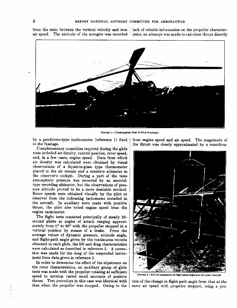
The lift and drag characteristics of the autogiro arepresented in Figures 3 and 4 and in Tables I and II.The area to which the force coefficients are referred is
the sum of the swept-disk area and the fixed-wing
_/.Z 1.4..,.2
_/.2
P_.a l
k
m
0 0 4 8 12
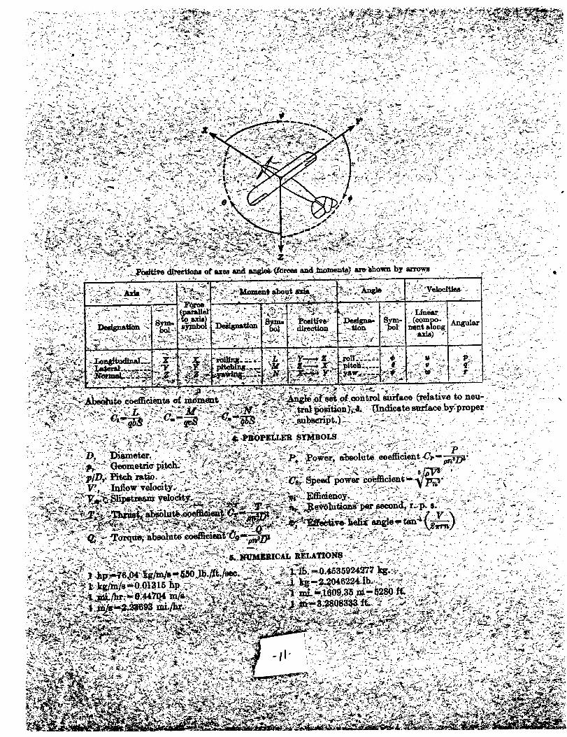
the state of operation of an autogiro rotor, is definedby the equation
Y cos
where V--true air speed, feet per second.a--angle of attack, degrees.
--rotor angular velocity, radians per second.
16 20 24 28 32 36 40 44 48 52 5_ 60 g4 68 72 76 80 84 88
Anqle of ot/ocl_ in deqr-ees,
FmUR_ 3.--Characteristic curves for PCA-2 autogtro
area, the wing being considered as extending throughthe fuselage. The use of the swept-disk area is arbi-trary, but an arbitrary selection is necessary, inas-much as the predominating velocity of the rotor bladesis not the velocity of flight. The inclusion of the fixed-wing area follows by analogy with a biplane. With thischoice of area the coefficients are of the same order of
/.2
/.0
o o on
o\".IJ O
E.6
/__. _'_'o
o
/.20 .2 .4 .E .8 1.0
Orog coefficient, CD
FmURZ 4.--Polar curve for PCA-_ autogiro
magnitude of those of a normal wing. The angle ofattack given in the graphs and tables is the angle be-tween the relative wind and a perpendicular to therotor axis lying in the plane of symmetry. Dragcoefficients, unless otherwise specified, have beencalculated from the drag of the aircraft as flown lessthe drag of the suspended instrument.
The rotor parameter _ is plotted in Figure 3 againstangle of attack. This parameter, which determines
O O
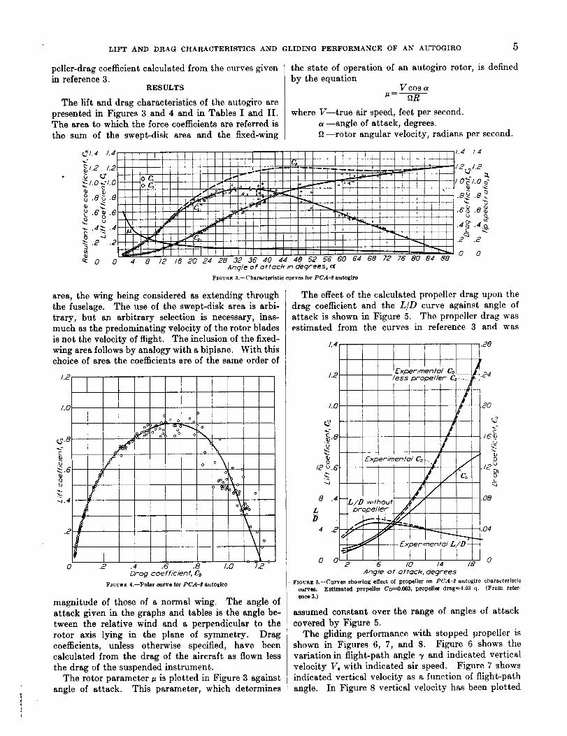
The effect of the calculated propeller drag upon the
drag coefficient and the LiD curve against angle ofattack is shown in Figure 5. The propeller drag wasestimated from the curves in reference 3 and was
0 0 02 6 /(2 /4 1,9
Angle of o/tack, degrees
FIGURE 5.--Curve8showing effectof propelleron PCA-_ autogirocharacteristic
curves. Estimated propeller0w_0.003,propellerdragffi4.93q. (From refer-
enoe3.)
assumed constantover the range of anglesof attack
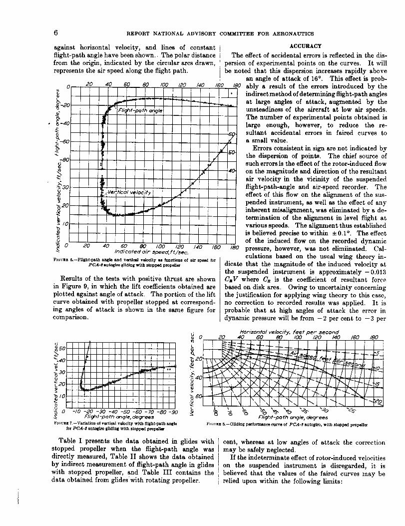
coveredby Figure5.The glidingperformancewith stopped propelleris
shown in Figures6, 7, and 8. Figure 6 shows thevariationin flight-pathangle_ and indicatedvertical
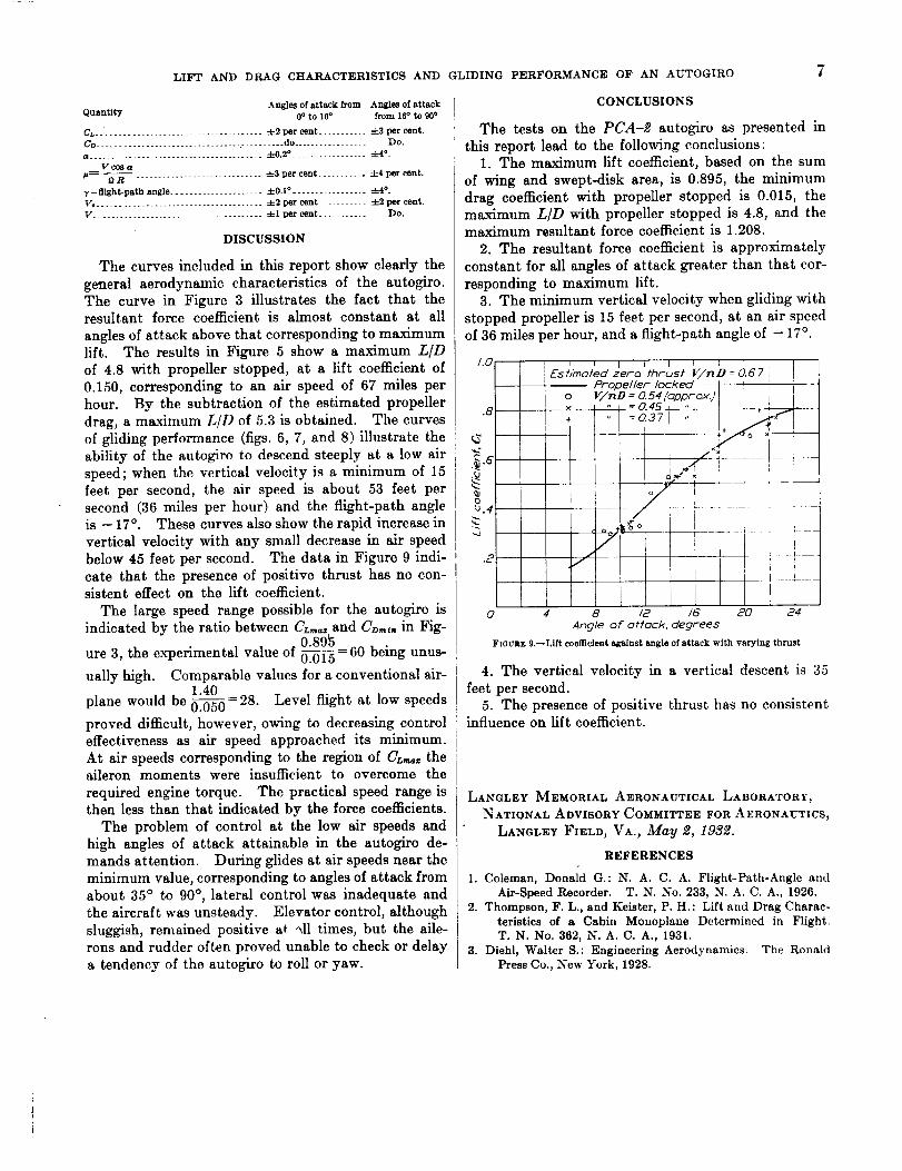
velocityVo withindicatedairspeed. Figure7 shows
indicatedverticalvelocityas a functionof flight-path
angle. In Figure8 verticalvelocityhas been plotted
6 REPORT NATIONAL ADVISORY COMMITTEE FOR AERONAUTICS
against horizontal velocity, and lines of constantflight-path angle have been shown.. The polar distancefrom the origin, indicated by the circular arcs drawn,represents the air speed along the flight path.
20 40 6O 80 _0 _0 /4O
£
.£
_ 20
b
0 20 40 60 80 I00 120 140 160Indicoted oir zpeed, f t./$ec.
F[ovnz &--Flight-path angle and vertical velocity as functions of air speed forPCA-f autogiro gliding with stopped propeller
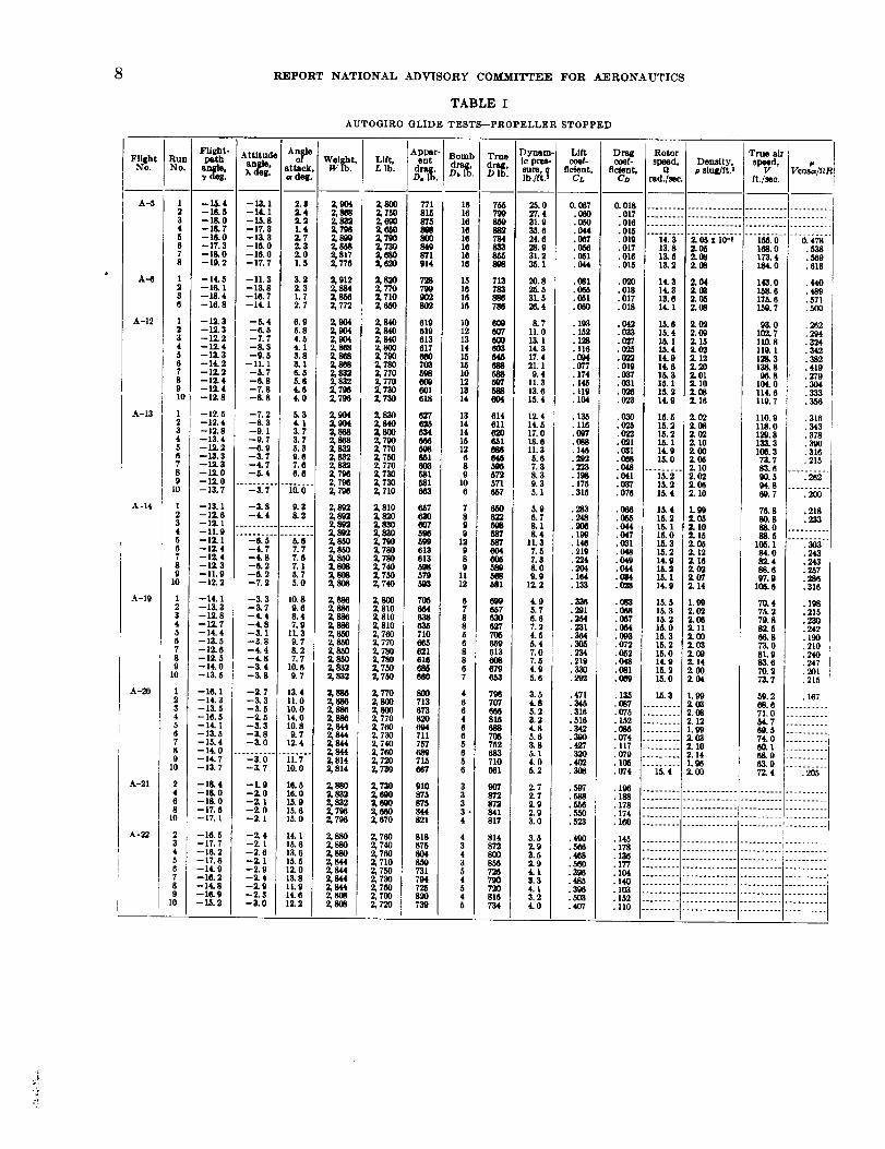
Results of the tests with positive thrust are shownin Figure 9, in which the lift coefficients obtained areplotted against angle of attack. The portion of the liftcurve obtained with propeller stopped at correspond-ing angles of attack is shown in the same figure forcomparison.
]/t
m
¢#
-I0 -20 -30 -40 -50 -60 -70 -80 -90
F/iqh f-pofh onc]le, degr'ees
_5o
.9
ql
_ o
_ 0
ACCURACY
The effect of accidental errors is reflected in the dis-
persion of experimental points on the curves. It willbe noted that this dispersion increases rapidly above
an angle of attack of 16% This effect is prob-/6'0 /80 ably a result of the errors introduced by the
indirect method of determining flight-path angles
at large angles of attack, augmented by theunsteadiness of the aircraft at low air speeds.
The number of experimental points obtained islarge enough, however, to reduce the re-sultant accidental errors in faired curves toa small value.
Errors consistent in sign are not indicated bythe dispersion of points. The chief source ofsuch errors is the effect of the rotor-induced flowon the magnitude and direction of the resultantair velocity in the vicinity of the suspendedflight-path-angle and air-speed recorder. Theeffect of this flow on the alignment of the sus-pended instrunmnt, as well as the effect of anyinherent misalignment, was eliminated by a de-termination of the alignment in level flight atvarious speeds. The alignment thus establishedis believed precise to within + 0.1% The effectof the induced flow on the recorded dynamic
/80 pressure, however, was not elimiinated. Cal-culations based on the usual wing theory in-
dicate that the magnitude of the induced velocity atthe suspended instrument is approximately-0.013CIV where Cs is the coefficient of resultant forcebased on disk area. Owing to uncertainty concerningthe iustification for applying wing theory to this case,no correction to recorded results was applied. It isprobable that at high angles of attack the error indynamic pressure will be from -2 per cent to -3 per
FmURZ 7.--Variation o1 vertical velocity with flight-path angle
for PCA-$ eutogim gliding with stopped propeller
4O
=.S--
Horizonfa/ ve/ocHy, feeP per" second60 80 '/00 /20 /40 ISO /80
----,-----..__.LJ 1
r--/- L 7".7-:-/--/-• ..., ,q_L
flight-peth angle ,degrees
FIGURI_&--Gliding performance curve of PCA-$ autOglro, with stopped propeller
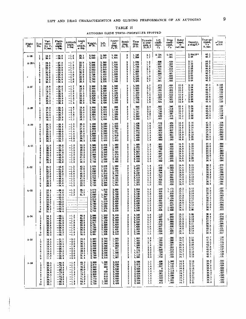
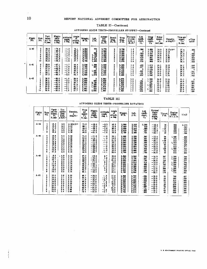
Table I presents the data obtained in glides with cent, whereas at low angles of attack the correctionstopped propeller when the flight-path angle was may be safely neglected.directly measured, Table II shows the data obtained If the indeterminate effect of rotor-induced velocitiesby indirect measurement of flight-path angle in glides on the suspended instrmnent is disregarded, it is1with stopped propeller, and Table III contains the i believed that the values of the faired curves may bedata obtained from glideswith rotating propeller. [ relied upon within the following hmits:
LIFT AND DRAG CHARACTERISTICS AND GLIDING PERFORMANCE OF AN AUTOGIRO
Anglesofattackfrom AnglesofattackQuantity 0°to16° from 16° to90°
CL....................................-4-2per cent..........._-3percent.Co ................................,-.........do................ Do.
a........................................"_0,2°................._ 4°.
VcoSa_ _-- .............................-4-3per cent...........±4 percent.
OR
v-_ght-path angle.....................-4-0.1°................._4°.V,.....................................4-2per cent ..........-4-2per cent.
V .......................................-_Iper cent.......... Do.
DISCUSSION
The curves inchlded in thisreport show clearlythe
general aerodynamic characteristicsof the autogiro.
The curve in Figure 3 illustratesthe fact that theresultant force coefficientis almost constant at all
anglesofattack above that corresponding tomaximum
lift. The resultsin Figure 5 show a maximum L/D
of 4.8 with propeller stopped, at a liftcoefficientof
0.150, corresponding to an air speed of 67 miles per
hour. By the subtraction of the estimated propeller
drag, a maximum L/D of 5.3 is obtained. The curves
of gliding performance (figs. 6, 7, and 8) illustrate the
ability of the autogiro to descend steeply at a low air
speed; when the vertical velocity is a minimum of 15feet per second, the air speed is about 53 feet persecond (36 miles per hour) and the flight-path angleis - 17 °. These curves also show the rapid increase in
vertical velocity with any small decrease in air speed
below 45 feet per second. The data in Figure 9 indi-
cate that the presence of positive thrust has no con-sistent effect on the lift coefficient.
The large speed range possible for the autogiro is
indicated by the ratio between CL_,z and CD,,, in Fig-0.895
ure 3, the experimental value of _ = 60 being unus-
ually high. Comparable values for a conventional air-1.40
plane would be _ = 28. Level flight at low speeds
proved difficult, however, owing to decreasing controleffectiveness as air speed approached its minimum.
At air speeds corresponding to the region of CL,,_ theaileron moments were insufficient to overcome the
required engine torque. The practical speed range is
then less than that indicated by the force coefficients.
The problem of control at the low air speeds andhigh angles of attack attainable in the autogiro de-mands attention. During glides at air speeds near the
minimum value, corresponding to angles of attack from
about 35 ° to 90 ° , lateral control was inadequate andthe aircraft was unsteady. Elevator control, although
sluggish, remained positive at. 4,11 times, but the aile-
rons and rudder often proved unable to check or delay
a tendency of the autogiro to roll or yaw.
CONCLUSIONS
The tests on the PCA-2 autogiro as presented in
this report lead to the following conclusions:1. The maximum lift coefficient, based on the sum
of wing and swept-disk area, is 0.895, the minimum
drag coefficient with propeller stopped is 0.015, themaximum LID with propeller stopped is 4.8, and themaximum resultant force coefficient is 1.208.
2. The resultant force coefficient is approximately
constant for all angles of attack greater than that cor-
responding to maximum lift.3. The minimum vertical velocity when gliding with
stopped propeller is 15 feet per second, at an air speedof 36 miles per hour, and a flight-path angle of - 17 °.
/'°_us,-- -- Propeller locked
t I [ o v/nD= o.54{oppcox}l I ix " = 0.45 "
.8 + =0.37 " I
I I I I 1 I 2" ' , !
0 4 8 /2 /6 20 24
Amgle of of lock, degrees
FIOURZ 9.iLlft coefficient against angle of attack with varying thrust
4. The vertical velocity in a vertical descent is 35
feet per second.5. The presence of positive thrust has no consistent
influence on lift coefficient.
LANGLEY MEMORIAL AERONAUTICAL LABORATORY,
NATIONAL ADVISORY COMMITTEE FOR AERONAUTICS,
LANGLEY FIELD, VA., May 2, 1932.
REFERENCES
1. Coleman, Donald G.: N. A. C. A. Flight-Path-Angle and
Air-Speed Recorder. T.N. No. 233, N. A. C. A., 1926.
2. Thompson, F. L., and Keister, P. H.: Lift and Drag Charac-
teristics of a Cabin Monoplane Determined in Flight.
T. N. No. 362, N. A. C. A., 1931.
3. Diehl, Walter S.: Engineering Aerodynamics. The Ronald
Press Co., New York, 1928.
8 REPORT NATIONAL ADVISORY COMMITTEE FOR AERONAUTICS
TABLE I
AUTOGIRO GLIDE TESTS--PROPELLER STOPPED
A-13
A-14
A-19
A-22
I0
1234567890
1234567890
I234567890
1234567890
24680
23456789
10
104
135
175
219
133
219
.¢618
N
324• 342• 382• 419
• 243• 243
_316
_242
•2_o i
....-!?...
.......... t
.......... i
?light Run iNo. No. i
A-26 12
A-20._ 123456
• 78
A-27
A-28
A-30
A-31
A -32
A-33
A-34
A-25
A-39
56789
10
12345679
10
123456789
123455780
10
LIFT AND DRAG CHARACTERISTICS AND GLIDING PERFORMANCE OF AN AUTOGIRO
TABLE II
AUTOGIRO GLIDE TESTS--PROPELLER STOPPED
Vert. I Flight- k ttitude[veloc- ] yam angle, Iity Vo I angm, X deg.
ft./see. I _ uog.I
19.0 --24.9 --1.820.0 --29.6 --1.0
19.3 --27.5 --1.719.6 --29.6 --1.522.9 --39.0 --1.517.4 --22.9 --I.720.9 --32.4 --1.519.5 --28.6 --1.6 ]18.6 --25.5 --1.718.3 --24.8 --1.6
9 20.4 --30.4 --1.6
1 I 18.9 --28.0 --1.72 I 17.4 --21.5 --1.73 19.3 --28.7 --1.64 17.4 t --22.9 --1.65 19.1 --26.8 --1.66 21.7 --33.0 --1.6
An_le _i_h_, Lift,
_ttack, L lb.
deg.
23.1 2.8 2,58028.0 2.840 2,470
25.8 2.886 2,56O28.1 2,868 2,50037. 5 2, 850 2, 21021. 2 2, 832 2, 61020.9 2,814 2.38027.0 2,796 2,45023.8 2,778 2,51023.2 2,760 2,50028.8 2,742 2,370 !
26.3 2,868 2,,_019.8 i 2,856 2,65027.1 2,844 2,50021.3 2, 832 2, 61025.2 _ 2,820 2,52031.4 2,808 2,360
7 18.2 I --25.0
8 18.5 t --26.5
1 I -2042 --23.23 18.3 --24.35 18.9 --26.76 20.4 --29.97 19. 1 --27.8
2 20.3 --29.53 24.2 --38.5 I4 23. 7 --3& 45 23.0 --40.06 23.4 --38.57 24.3 --42.38 20.2 --31.39 20.3 --31.7
1 21.0 --33.82 20_ 5 --31.73 28.8 --50.34 23. 4 --37.05 22.3 --36.76 i 24.7 --43.37 28. 3 --52. 48 19. 5 --32. 0
1 25.0 --43.62 31.3 --61.23 ! 20.fl --32.84 27.2 --50.25 22.0 --33.76 27.5 --49.47 20.8 --33.58 22.2 --25.09 20.8 --34.4
1 33.4 --69.42 35.7 --74.83 34.1 --63.24 33.6 --63.6
34.9 --73. 334.0 --62.032.7 --60.930.3 --55.032. 4 --52. 331.1 -59. 4
34.4 --62.134.3 --63.334.3 --65.433.9 --6£222.8 --35.023.0 --36.420.5 --31.630.2 --53.232. 0 --_). 5
16.8 --21.518.3 --2_.116.6 --22.418. 8 --25. 416.4 --20.118.6 --24.316. 6 --21• 517.6 --23.817.1 --23.4
33.4 --64.833.0 --7_825.2 --72.438.3 -90.034.8 --72.934.4 --71.835.1 --72. 934.7 --72.9
I 33.7 ' --66.6
j_.l I -_.8
--1.7 23.3--1.6 24.9
--1.8 18.5--1.7 21.5--1.5 22.8--1.6 25.1--1.7 28.2--1.7 26.1
--1.5 28.0--1.5 37.0--1.4 37.0--1.4 38.6--1.5 37.0--1.5 40.8--1.6 29.7--1.5 30.2
--1.5 32.3--1.5 30.2--1.4 48.9--1.5 35.5--1.5 35.2--1.4 41•9--1.3 51.1--1.5 30.5
--1.3 42.3--1.3 59.9--1.6 31.2--1.6 48.6--1.5 35.2--1.5 47.9--1.5 32.0--1.5 33.5--1.5 32.9
--1.3 68.1--1.3 73.5--1.3 61.9
--1,5 60.6--1.7 61.6--1.5 63.9-I. 6 62. 6--1.8 33.2--1.8 34.6--1.8 29.8--1.6 51.6--1.5 59.0
--2.0 19.5--2.0 24.1--2.0 20.4--1.9 24.5--2. I 18. 0--2.0 22.3--2.0 19.5--2.0 21.8-2.0 21.4
--1.6 63.2--1.5 77.3--1.5 70.9--1.7 90.0--1.4 71.5--1.6 70.2
i --1.7 71.2I --1.7 71.2i --1•8 64.8i --1.9 61.9
2,796 2,5502, 784 2, 490
2,860 2,6802,843 2,6132, 826 2, 5752.804 2,5082, 787 2, 4172, 770 2, 450
2,900 2,5202, 890 2, 2602,88O 2,26O2.870 2.2_)2, 860 2, 2402,840 ! 2,1002, 830 2, 4102,820 2,4OO
2, 860 2, 3762, 845 2, 42O2,83O 1,8082, 815 2. 2492,806 2,2452,785 2.0272, 770 1,6902, 755 2, 336
2,870 2,O782,855 1,3752,840 2,3852,825 1,8102, 810 2, 2532, 795 I, 8202, 780 2, 3182,765 2,3342, 755 2,269
2. 870 1,0102, 855 7482,840 1,2802,825 1,2572,810 8O62,79.5 1,3102,78O 1,2502'765 1,5852,75O 1,2782, 725 1,391
2,895 1,2522,869 1,2892,843 I, 1802, 817 1, 2242,791 2,29O2,765 2,2302, 739 2, 3302,687 1,6082,661 1,338
2,_0 2,7OO2,88O 2,5S02,86O 2,04O2,84O 2,54O2,820 2,05O2,806 2,55O2, 780 2, 5902,76O 2.5202, 740 21510
2,890 1,2262, 870 65,572,330 8632, 840 02, 820 8302, 800 8742, 780 8182,770 8132, 7,5O i, 9902,730 1,202
&ppar- [ent i _°mb: True
drag, drag,
D,_l '. 9b lb. D lb.
I, 200 2 1, 1981,401 2 1, 399
1, 331 2 1, 329 I1,418 2 1,416 11, 794 2 i, 792I, 198 2 I, 1011,510 2 1, 508 !1,330 2 1, 337 iI, 195 2 I, 1931,158 2 I, 1561,388 2 1,386
1,350 2 I, 348I, 048 2 1, 0461,367 2 1,365I, 102 2 I, 106I, 272 2 1, 2701,530 2 1,5281,180 2 1,1781, 245 2 i, 243
996 3 9951,120 3 1, 1171, 164 3 1, 161i, 259 2 I, 257i, 391 2 1,3891,294 2 L 1,292
I, 430 2 1,428
I, 800 i2 I, 79_.
2 1,788I, 7901,847 1,8451,775 1,773I, 910 1,906I, 471 2 1,469
I, 482 22 I, 4801,590 1,5881,496 1, 4942,177 2 2,1751.695 2 1, 693I, 574 2 I, 6721,910 2 1,9082,194 2 2,1921,460 2 1,458
1,980 2 1,9782,5Ol 2 2,4991,539 2 1,5372,170 2 2,1681,680 2 1,6782,121 2 2, 119I, 525 2 I, 5331,587 2 1,585I, 554 2 I, 552
2,686 2 2,6842,750 2 2,7482.53o 2 2,5282, 530 2 2, 5282,692 2 2,6902,468 2 2,_2.43O 2 2,4282,20O 2 2,2582, 430 2 2, 4282,35o 2 2,348
2.55o 2 2,5482,b06 2 2,5582,580 2 2.5782, 530 2 2, 5281,602 2 1,600I, 640 2 I, 6381,435 2 1,4332,150 2 2,1482,310 2 2'3O8
1,063 3 1,0601,267 2 1,1,009 3 1,086I, 262 2 t, 280
967 3 9041,157 3 I, 1541,020 3 1,017I, I15 2 I, 1131,087 2 1,085
2,610 2 2,6082, 82O 2 Z 8182. 72O 2 Z 7182,840 2 2,8382, 706 2 2, 69S2,66O 2 2'6582,660 2 2,6582,640 2 2,6382,52o 2 2,5182'450 2 2,448
)ynam- Lifttc pres- [ coeflt-sure, q cient,
lb./ft.t CL
Z 1 0. 7341.7 .851
1.9 .8_1. 7 .8871.4 .9292. 1 .741 ;1.6 .901 i1.7 .8441.9 .7712.0 ,7471.7 .841
1.7 .8722.3 .6851.7 .8882. 1 .7411.8 .8191.6 .8651.9 .7781.8 .834
2.4 ._32. I .7452.0 : .7501.9 .7921.7 .8201.7 .841
1.8 .8191.6 .8171.6 .8551.4 .9821.5 .87&1.4 .8831.6 .b841.6 .880
1.6 .9011.7 .8621.5 .7091.5 .8811.5 .8831.4 .8471.4 .7131.5 .949
1.4 .872I. 4 .5991.6 .9041.4 ._41.5 .915I. 4 .7671.5 .9051.6 .831I. 5 .921
1.4 .4421.5 .3041.6 .4851.5 .4931.4 .3381.6 .4811.5 .5301.5 .6431.4 .5371.4 .608
1.6 .5121.6 .4871.5 .4631.5 .4791.7 .8131.6 .8171.6 .8411.5 .6201.5 .524
2. 2 .7131.9 .7932. l .7501.9 .7802.4 .6412.2 .6902. 2 7022. 0 ./342.0 .755
1.5 .4981.5 .2201.4 .2571.4 01.4 .344I. 4 .3611.5 .3331.4 .3421.5 .4431.5 .472
Dragcoem-cieDt,
Co
O.341.481
.420
.503
.754.313.572.451.366.346.493
Rotor
;tipS, Density,p slug/ft3Ld./sec.
....... 2.04x lO-a
.464 15.0• 270 15. 2.484 15.2.313 15. 0.412 15. 0.561 15. 2.361 14. 9.416 15. 0
.246 15.4• 318 15. 4.339 15.2•397 15.1.478 ! 15.2.446 15. 1
.464 ' 15.0
.659 15. 0• 678 ' 14. 9.807 15. I.695 15. 0.801 14.9.539 14. 9.543 14. 8
.602 14.8
.535 14. 8
.852 14.8
.663 14.8
.655 14. 8
.803 14.8
.933 14.8
.593 14.8
.833 14.81.982 15. I.583 14.9.040 14.9.681 14.9.891 15.0.606 14.8.582 14.8.630 14.8
1.175 15. 21. I16 15.1
.958 15.1
.990 15.01. 134 15.0
.904 14.9,951 14.9•917 14. 71.022 14.71.029 14.9
.967 15.3
.989 15.11.010 15.2
.992 15.2•569 15. 0.600 14.9.517 14.9.838 14.7.937 14.6
.280 14.8
.388 14.5
.309 14.7
.387 14.8
.233 14.5
.313 14.5
.275 14. 7
.325 14.5
.325 14.7
1,060 14.91.142 14.91. 121 15. 01,171 14.91.114 14.7L098 14.71.080 14.71.109 14.71.031 14.7.960 14.7
['rueair.speed,
VTft./see,
45. i [2.08 40.7[
2.112.I02.132.982.O52.072.052.O92.O5
2.122.042.062.092.042.042.06_06
2.042.032.062. 112.062.06
2.152.142.142.112. 142•152.152. 16
2. 182. 182. 182. 182. 162.172.2O2. 15
2.152.132.162.152.152.142.132.152.15
2.122.122.142.142.132.172.152.132.112.08
2.O62.122.122.122.112.142. 142.122. 15
2.152.232.182. 162. 152. 172. 132.142.13
2.142.172.102.142.172. 192.172.132.172. 21
9
42.2 i .........t
39. 7 .......... [36.4 .........44.5! .........
39. 0 .........40.743.3 . ........43.5 .........40•3 .........
40. 2 O. 10847.4 .12840. 2 .10944. 7 .12242.3 .11139.8 .09843. 1 .11741.4 . Ii0
48.4 .13345. 2 .12144.4 .11942.1 .11240.9 .10640.9 .I08
41.2 .10638.8 .09238.2 .09135. 8 .08237. 6 .08936. 1 .08238.8 .10038.6 .106
37.8 .09439.0 .098
37.2 .071 I37. 2 .08937.3 .09036. 0 .07935. 7 .06530.8 .094
33.2 .07925.7 .05138.0 .09525.4 .06836.8 .08825. 2 .07037.7 .00433.7 .09536.8 .091
25.7 ,03737.0 .02838.2 .05137. 5 .04936.4 .03138,5 .05437. 4 .05437.0 .06436.6 .05133. 1 .055
33.9 .05638.4 .05437.7 .04837. 7 .05139.7 .09838.8 .09539. I . I0137.7 .07036. 8 .057
45. 7 .13041.6 .I1643. 6 .12442. 7 .11547.8 .13845.0 .12745.3 .12943.5 .12343. L . 121
36.9 .0.5033.7 .02436.9 .03636.6 .0_36. 4 .03536. 2 .03736.7 .03636.3 .03636. 7 .04736.9 .053
10 REPORT NATIONAL ADVISORY COMMITTEE FOR AERONAUTICS
TABLE II--Continued
AUTOGIRO GLIDE TESTS--PROPELLER STOPPED--Continued
Flight Run
I'4"o. No.
89
10
A-41 23456
A-42 123489
10
Vert.veloc-Ity V,ft ./see.
36.037.085.433.333.632.331.3
33.833.937.0'33.534.133.2
36.836.1
32. 225.234.923-6
Flight- Attitude
tJ_i] allele Pangm. ), 8.-/(leE.
--74.4 -1.3 73.1--90.0 --1.4 00.0--71.1 --1.6 09.5--66.3 --1.6 , 64.9--64.6 --1.7 62.9 !--61.6 --1.8 i 59.8--59.5 --1.8 i 57.7
--67.1 --1.7 65.4--71.3 --1.9 69.4--90.0 --1.8 90.0--67.8 --1.8 66.0--83.7 --1.8 81.9--66.5 --2.0 64.5
-000 I 00o-_8 [ - _.8-41.0 I -2.3 _.7--03.4 --2.1 81.3--43.8 --2.1 41.7--85.6 --2.1 83.5--39.6 --1.9 37.7
A I. Weight,[attack, Wlb. I LII_'.a deg.
2,880 7762,800 02,8902, 830 1,1282, 790 1,1972, 770 1,3182,780 1,400
2,820 1,80_2,79o2,770 02, 740 I,2, 72O
2,690 [ 1,072
2,880 ] O2, 810 1, _2,710 _ 1,_
2,680 I 2102,98O 2,O5Oi
Appat- [ Bomb Trueent
d",D lb.
2,77O 2 I 2,7682,8_0 2 2,8582, 790 2 2, 6982,500 2 2,888
2,5 o 22,t-tll 22,38O 2 2,378
2,600 2 2,5982,e4o 2 2,_8
3.770 _1 2,7_82,-,4o 2,,_s ;2,700 2,698 J2,470 2 _468i
2, 880 2 2, 8782, 820 2 2, 8181,890 [ 2 1,8582, 510 I 2 2,5O81,874 [ 2[ 1,8722, 670 2 I 2, 6681,697 2 _ 1,695
D ynam-ic pres-sure, 9Ib./ft.s
1.5 i1.41.51.51.51.51.4
1.41.41.51.41.31.4
1.41.41.41.41.41.31.5
Liftcnsm-cfent,
eL
.3040
.852.459.470• 585.579
• 453.377
0.438• 136.452
0.194.906.550• 824.096.832
cient,Co
1.M1.1791.067 11.0._0.987.990.982 I
I. 072 15.11.109 14.91.124 14.91.067 , 14.91 2'27 14.61_o4o 14.8
1.258 l 14.91.184 I 15.2
•781 15. I1.097 15.0.787 14.9
1. 214 14. 7.f_q8 14.8
Rotorspeed,
t]ad ./sec.
14.915.0119 iIt 814. 614. 714.6
Density,p slug/fl.s
2.17x]0-t2.132.172. 212.202.172.17
2.132.192.152.152. 212. 14
2,142. I02.072.082.122.122.13
1
rue elr-[
_VI_T, I u P'cosa/fiR
36.737. 4 . _1936.3 .047
37.1 ._._36.736.3 .059
36.7 .0043_35.836.336.2 .04734.3 .01236.2 .043
35.5 i 036. 6 .02136.9 .08536.0 .05136.4 i ,08135.0 .012
37.0 ._8
TABLE III
AUTOGIRO GLIDE TESTS--PROPELLER ROTATING
F_o. ht
A-44
A-45
A--46
A--51
RunNo.
Vefti- Dy-calve- nsmieIodty, pres-
V, sure,ft./see q lb/ft.t
15. 4 ..,5.615.6 6.217.3 2.210. 1 4.916.5 2.2
13.0 5.613.7 3. 11%7 2.213.2 4.913.8 2.917.0 2.112.9 5.114.8 3.017.2 2.0
0.6 ,4.912.3 3.015.7 2.09.4 6.3
11.8 &314.5 2.39.1 6.0
12.0 3.014.1 2.2
16.5 2.614.4 3. 1l&2 5.514.8 2.514.2 3.214.2 5.315.4 2.113.9 3.415.0 3.4
Density,#
slug/R.s
2. 16XIO-:Z 182. 172.162.18
2.162.152.182. 182.152.162. 172.152. 16
2.142.132.142.132. 142. 142. 132. 132.14
2. l02.112.112.122. 162. 112.162.082.90
True Flight-air
pathspeed anl[le,Vrft./see, v, aqt.
71.0 --12.6_.1 -12.046.4 -22.367.6 --13.844.9 --2L5
71.0 --11.053.9 --14.745.3 --23.007.6 --11.252.0 --15.343.6 --22.968.5 --10.852.9 --16.242.8 --23.7
67.5 --8.252.8 --13.542.9 --21.57'0.6 --7.655.3 --12.146.2 --18,268.9 --7.653.7 --12.9tf_l --1&2
49.7 --18.254.4 --15.471.9 --10.648.5 --17.854.8 --l&l70.9 --11.643.9 --21.967.4 --14.072.4 --11.9
attack,deg. ), a deg.
--2.3 10.2--2.1 10.9--1.8 20.6--2.2 11.6--L8 19.9
--.0 I0. I--.2 14.5
--I.i 21.9--.5 10.7-.1 15.2-.9 'P:t.0--.6 10.2--.2 16.0
--1.1 22.6
2.7 10.91.9 16.4
--.3 21.32.2 9.81.6 13.7
--.2 18.0Z5 10. I1.8 14.7.3 18.4
--.3 17.9--1.5 13.9--2.7 7.9
--.3 17.6--1.3 12.8--2.8 8.7
0 21. 9--1.5 12.5--2.7 0.2
Weight, Lift.Wlb. L lb.
2,88O 2,8102.840 2.7702,82O 2,6102,810 2,73os,700 2,5oo
2,88o 2,83o2, 870 2, 78O2,86O 2,63O2,840 2,7902,8_0 2,73O2,82O 2,6OO2, 810 2, 7002,8OO 2,69O2,780 2,850
2,88O 2,8502,87O 2,7OO2,86O 2,_002, 84O 2, 8102,830 2,7602,82O 2,_802, 810 Z 79O2,00o 2,73o_,r90 2,640
2,s00 2,7502, 87O 2, 7702,800 2,8OO2,83O 2,69O2,810 2,7102,700 2,73O2, 77O 2, 6702, 7,5O 2, 67O2, 730 2, 670
NormalLift flight
coeffi- Thrust,cient, path
an_le, T lb.CA3' oeg.
0.366 --13.4 18.319 --13. 7 10
• 800 --22. 1 --21.327 --14.0 --14• 701 --22. 1 19
.507 --13.4 94
.527 --16.8 90
. _96 -22.1 --46
.3_ --14.0 I16
.554 --17.5 95• 740 --23. 3 I0.321 --13.8 12"2.527 --17.2 34• 763 --24. 8 43
.34_ --14.0 267
._7 --17.2 171
.7])5 --24. 8 1.55
.314 --13. 8 271• 498 -- 16. 3 193.693 --21. 1 131.327 --13.9 284.5_ --17.2 185.715 --22. I 178
.685 --18.9 22
.6_ --16.8 44
.303 --13.4 91
.637 --19.5 72
.497 --16,6 58,30_ --13.6 76.731 --23. 3 47.490 --18. 1 83.292 --13,5 46
Engine
speed, V/nDN r.p.m.
83O 0. 570820 .5_2500 .605830 .543510 .588
1,020 .465810 .444610 .496
I, 010 .447815 .426610 .477
i, 020 .448815 .433610 .469
1, 290 .3491, 040 .339
760 .3771,280 .3681, 020 .362
750 .406I, 290 .357I, 020 .352
770 i ,391
760 .437660 .550815 .589750 .432670 .544820 .576750 .390660 .580820 i .589
/
U,S. GOVERNMENT PRINTING O_FICE:I�$|
!