٢٠٠٧ : ٥٥٩ وﺰﻳا س ق م Steel tubes for water and sewagepontofocal... · ISO...
22
ﻳﺰو ا س ق م٥٥٩ : ٢٠٠٧ ISO 559 : 1991 SASO ISO 559 : 2007 ISO 559 : 1991 واﻟﺼﺮف ﻟﻠﻤﺎء اﻟﺼﻠﺐ أﻧﺎﺑﻴﺐ. Steel tubes for water and sewage
-
Upload
nguyenmien -
Category
Documents
-
view
241 -
download
3
Transcript of ٢٠٠٧ : ٥٥٩ وﺰﻳا س ق م Steel tubes for water and sewagepontofocal... · ISO...

٢٠٠٧: ٥٥٩م ق س ايزو ISO 559 : 1991
SASO ISO 559 : 2007 ISO 559 : 1991
.أنابيب الصلب للماء والصرف Steel tubes for water and sewage

تقديم وطني
بتبني المواصفة القياسية الدوليـة التاليـة للمواصفات والمقاييس قامت الهيئة العربية السعودية
: عليها أي تعديالت فنية دون إدخال
ISO 559 : 1991 " أنابيب الصلب للماء والصرف.. "
NATIONAL FOREWORD
The Saudi Arabian Standards Organization (SASO) has adopted without any technical changes the International Standard: ISO 559 : 1991 “Steel tubes for water and sewage”

INTERNATIONAL STANDARD
Second edition 1991-02-15
--
Steel tubes for water and sewage
Pubes en acier pour eaux et eaux rhidueiles
-- --
--- ---------- Reference number
ISO 559:1991(E)

ISO 559:1991(E)
Contents Page
1 Scope . . . . . . . . . . . . . . . . . . . . . . . . . . . . . . . . . . . . . . . . . . . . . . . . . . . . . . . . . . . . . . . . . . . . . . . . . . . . . ..*................. 1
2 Normative references . . . . . . . . . . . . . . . . . . . . . . . . . . . . . . . . . . . . . . . . . . . . . . . . . . . . . . . . . . . . . . . . . . . . . . . 1
3 Definitions and Symbols .................... ............................................. 1
3.1 Definitions . . . . . . . . . . . . . . . . . . . . . . . . . . . . . . . . . . . . . . . . . . . . . . . . . . . . . . . . . . .._........................ 1
3.2 Symbols .,..,..................,........................,...........,......................,..... 1
4 Information to be supplied by the purchaser . . . . . . . . . . . . . . . . . . . . . . . . . . . . . . . 2
4.1 Mandatory information . . . . . . . . . . . . . . . . . . . . . . . . . ..-..................................... 2
4.2 Optional requirements .,.....,..............................................,.......... 2
4.3 Designation . . . . . . . . . . . . . . . . . . . . . . . . . . . . . . . . . . . . . . . . . . . . . . . . . . . . . . . . . . . . . . . . . . . . . . . . . . . . . . . . . . . 2
5 Manufacturing process . . . . . . . . . . . . . . . . . . . . . . . . .._................................_..._... 3
5.1 Steel-making processes and deoxidation procedures . . . . . . . . . . . . . 3
5.2 Tube-making process . . . . . . . . . . . . . . . . . . . . . . . . . . . . . . . . . . . . . . . . . . . . . . . . . . . . . . . . . . . . . . . . . . . 3
5.3 Heat treatment, delivery condition . . . . . . . . . . . . . . . . . . . . . . . . . . . . . . . . . . . . . . . . . . . . . 3
6 Chemical composition, mechanical properties and weldability 4
6.1 Chemical composition . . . . . . . . . . . . . . . . . . . . . . . . . . . . . . . . . . . . . . . . . . . . . . . . . . . . . . . . . . . . . . . . . 4
6.2 Mechanical properties . . .._............................................................ 4
6.3 Weldability . . . . . . . . . . . . . . . . . . . . . . . . . . . . . . . . . . . . . . . . . . . . . . . . . . . . . . . . . . . . . . . . . . . . . . . . . . . . . . . . . . . . . 4
7 Dimensions, masses and tolerantes . . . . . . . . . . . . . . . . . . . . . . . . . . . . . . . . . . . . . . . . . . . . 5
7.1 Dimensions and masses .......... ............................ ....................... 5
7.2 Tolerantes . . . . . . . . . . . . .._........-............................................................ 6
8 Appearance and soundness .._......................................................, 7
9 Inspection and testing . . . . . . . . . . . . . . . . . . . . . . . . . . . . . . . . . . . . . . . . . . . . . . . . . . . . . . . . . . . . . . . . . . . . 8
9.1 General requirements . . . . . . . . . . . . . . . . . . .._............................................. 8
9.2 Test methods and results . . . . . . . . . . . . .._............................................. 9
9.3 Invalidation of tests .,.................................................................. 10
0 ISO 1991 All rights reserved. No part of this publication may be reproduced or utilized in any ferm or by any means, electronlc or mechanlcal, Includlng photocopylng and mlcrofiim, without Permission in writing from the publlsher.
International Organization for Standardization Case Postale 56 l CH-1211 Geneve 20 l Swltzerland
Printed in Switzerland
ii
ISO 559:1991(E)
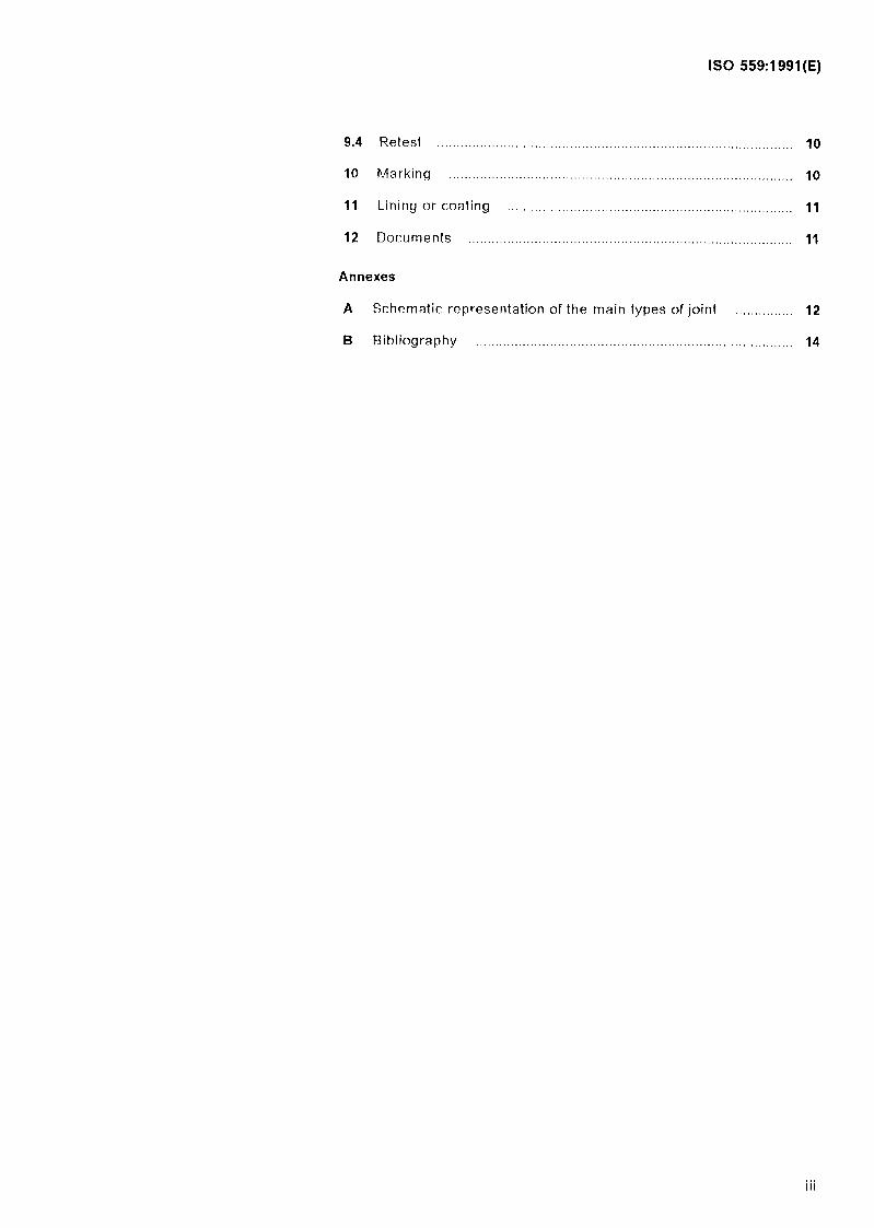
9.4 Retest . . . . . . . . . . . . . . . . . . . . . . . .
10 Marking . . . . . . . . . . ..s....*...
11 Lining or coating . . . . . .
12 Documents . . . . . . . . . . . . . . . .
Annexes
. . . .
. . . .
,...
. . . .
.*..
. . . .
. . . .
. . . .
.......
.......
.......
.......
. . . .
. . . .
. . . .
. , . .
...........
...........
...........
...........
. . . .
..,.
. . . .
. . . .
..................... 10
............ ......... 10
........ ............. 11
....... .............. 11
A Schematic representation of the main types of joint ............... 12
8 Bibliography ....................................................... .......................... 14
. . . Ill

ISO 559:1991(E)
Foreword
ISO (the International Organization for Standardization) is a worldwide federation of national Standards bodies (ISO member bodies). The work of preparing International Standards is normally carried out through ISO technical committees. Esch member body interested in a subject for which a technical committee has been established has the right to be represented on that committee. International organizations, govern- mental and non-governmental, in liaison with ISO, also take patt in the work. ISO collaborates closely with the International Electrotechnical Commission (IEC) on all matters of electrotechnical standardization.
Draft International Standards adopted by the technical committees are circulated to the member bodies for voting. Publication as an Inter- national Standard requires approval by at least 75 % of the member bodies casting a vote.
International Standard ISO 559 was prepared by Technical Committee ISO/TC 5, Ferrous metal pipes and metallic fittings.
This second edition cancels and replaces the first edition (ISO 559:1977), of which if constitutes a technical revision.
Annexes A and B of this International Standard are for information only.

INTERNATIONAL STANDARD ISO 559:1991 (E)
Steel tubes for water and sewage
1 Scope
This International Standard specifies the technical conditions for delivery of seamless and welded steel tubes for the conveyance of water and sewage at temperatures between - ‘IO “C and 120 “C.
lt does not apply to steel tubes in accordance with ISO 65 and similar plain end tubes (for Service dis- tribution).
2 Normative references
The following Standards contain provisions which, through reference in this text, constitute provisions of this International Standard. At the time of publi- cation, the editions indicated were valid. All stan- dards are subject to revision, and Parties to agreements based on this International Standard are encouraged to investigate the possibility of ap- plying the most recent editions of the Standards in- dicated below. Members of IEC and ISO maintain registers of currently valid International Standards.
ISO 65:1981, Carbon steel tubes suitable for screwing in accordance with ISO 7-1.
ISO 404:-1’ , Steel a,id steel products - General technical delivery requirements.
ISO 4200:1991, Plain end steel tubes, welded and seamless - General tables of dimensions and masses per unit length.
ISO 525211991, Steel tubes - Tolerante Systems.
ISO 6761:1981, Steel tubes - Preparation of ends of tubes and fittings for welding.
ISO 689211984, Metallic materials - Tenside testing.
ISO 7438:1985, Metallic materials -- Bend fest.
ISO 849211986, Metallic materials - Tube - Flatten- hg test.
ISO 9302:1989, Seamless and welded (except sub- merged arc-welded) steel tubes for pressure pur- poses - Electromagnetit testing for verification of hydraulic leak-tightness.
3 Deflnitions and Symbols
3.1 Definltions
For the purposes of this International Standard, the following definitions apply.
3.1.1 seamless tube: Pierced solid product, hot worked and hot or cold finished.
3.1.2 welded tube: Flat product formed into a cir- cular shape and longitudinally or spirally welded.
3.2 Symbols
For the purposes of this International Standard, the following Symbols apply; these Symbols are in ac- cordante with those specified in ISO 3545-1, ISO 6708 and iS0 6892.
DN nominal size
outside diameter of the tube, in millimetres
1 7
thickness of the tube, in millimetres
distance between the platens of the test machine, in miI1imetres
mass per unit length, in kilograms per me- tre
R rn tensile strength, in newtons per Square millimetre
R eH upper yield stress, in newtons per Square millimetre
1) To be pubM~ed. (Revision of ISO 404:1981)
1

ISO 559:1991 (E)
R eL
R PO92
x t0,5
n
7 cO
PE
r; L.
K
lower yield stress, in newtons per Square millimetre
proof stress (0,2 % non-proportional elon- gation), in newtons per Square millimetre
proof stress (0,5 % total elongation), in newtons per Square millimetre
percentage elongation after fracture, ex- pressed as a percentage of the original gauge length (LJ, I, = 5,65&
original Cross-sectional area of the parallel length, in Square millimetres
test pressure, in bar*)
stress which occurs in the metal during the hydraulic test, in newtons per Square milli- metre
flattening test constant; it varies depending on the grade of steel
4 Information to be supplied by the purchaser
4.1 Mandatory information
The purchaser shall specify or tonfirm in his enquiry and Order
a) the quantity ordered (total tonnage, total length . or number of tubes);
b) the number of this International Standard:
c) the grade of steel;
d) the outside diameter and thickness;
e) the length;
f) the end preparation (bevelled ends or special joints);
NOTE 1 Until International Standards for special joints are available the purchaser should indicate in the enquiry and Order the national Standards or other specifications which the manufacturer is required to meet.
9) the type of external coating and/or interior lining, as agreed previous ly with the man ufacture K
h) the document to be supplied when the tubes are delivered, which is usually either a Statement of compliance or an inspection certificate (see 4.2 and clause 12).
2) 1 bar = 0,l MPa
.
4.2 Optional requirements
Certain Options and supplementary requirements may be specified, including the following:
- the steel-making processes and deoxidation procedures (See 5.1);
- the tube-making process (see 5.2);
- removal of inside seam reinforcement (see 5.2.2);
- delivery of jointers (see 5.2.2);
- delivery condition (see 5.3.1 and 5.3.2);
- ladle analysis (see 6.1.1);
- product analysis (see 6.1.2);
- delivery lengths (see 7.1.3);
- end preparation (see 7.1.4);
- special tolerantes on outside diameters (see 7.2.1.2);
- the removal of inside seam reinforcement of both ends of submerged arc welded tubes (see 5.2.2);
- the selection of samples and tests in the pres- ence of the purchaser or of a representative of the purchaser (see 9.1.1);
- special hydraulic test pressure (see 9.2.4.1);
- type of lining or coating (sec clause 11);
- type of documents (see clause 12).
The purchaser should specify his requirements in the enquiry and Order.
If the Options and particular requirements are not specified in the enquiry and Order, their choice will be at the discretion of the manufacturer.
4.3 Designatlon
The tubes shall be designated, in the sequence given, by the following:
- the type of product (seamless or welded tube);
- the number of this International Standard;
- the grade of steel; L
- the outside diameter and the thickness.

ISO 559:1991 (E)
EXAMPLE
Submerged arc welded steel tubes in accordance with ISO 559, of steel grade ST360, of outside diam- eter 1016 mm and thickness 8,8 mm, in random lengths, shall be designated as follows:
Submerged arc welded tubes ISO 559~ST360- 1016 x 8,8
5 Manufacturing process
5.1 Steel-making processes and deoxidation procedures
The steel-making processes and deoxidation pro- cedures are at the choice of the manufacturer. At the request of the purchaser, the manufacturer shall state the steel-making processes and deoxidation procedures used.
5.2 Tube-making process
5.2.1 Seamless tubes
Seamless tubes shall be manufactured using a seamless process by hot working with or without subsequent cold finishing.
5.2.2 Welded tubes
Welded tubes shall be manufactured from hot-rolled steel Strip, sheet or plate, by longitudinal or spira welding as shown in table 1.
Table 1 - Welding processes
I 1) See 5.3.2.
Electric resistance, including induction welding
-- X’)
- X’)
Submerged arc welding
X
X
I
The production process for submerged arc welded tubes shall include at least one welding pass on the inside and at least one welding pass on the outside. Where specified by the purchaser, both ends shall have the inside seam reinforcement removed for a distance to be agreed (see 4.2).
Butt welded tubes and electric resistance, including induction welded, tubes shall be delivered with the
external weld upset removed. By agreement be- tween the manufacturer and the purchaser, the internal weld upset may be trimmed. Butt welded and electric resistance, including induction welded, tubes shall not have skelp end welds.
Unless otherwise specified in the enquiry and Order, submerged arc welded tubes may be delivered in short lengths welded together, i.e. jointers, provided that the joints are made by the Same method of welding and inspected to the Same Standards as those used for the manufacture of the tubes (see 4..2 and 9.1.3.1).
5.2.3 Cholce of the tube-maklng process
If the tube-making process, and in particular the type of welding, is not specified in the enquiry or Order, this process is at the Option of the manufacturer.
5.3 Heat treatment, delivery condition
5,3.1 Seamless tubes
Seamless tubes shall be delivered in a metallurgical condition permitting the manufacturer to guarantee the properties given in table5.
At the purchaser’s request, he shall be informed of the delivery condition.
5.3.2 Welded tubes
The delivery conditions for welded tubes are given in table 2. At the purchaser’s request, he shall be informed of the delivery condition.
Table 2 - Delivery conditions for welded tubes
Manufacturing process Delivery condi tion (all grades)
Submerged arc welding Tubes as welded with or without cold expansion Heat-treated tubes
Butt weiding or electric re- slstance Including induction weldlng
As-welded tubes Tubes with weld area heat treated Heat-treated tubes
Butt welding or electric re- At the Option of the manufac- sistance including induction turer welding wlth subsequent hot rolllng _ .- as-hot-rolled tubes
-- heat-treated tubes
Butt welding or electric re- Heat-treated tubes sistance Including induction welding with subsequent cold finishing
3

ISO 559:1991(E)
6.1.2 Product analyses 6 Chemical composition, mechanical properties and weldability
6.1 Chemical composition
Table 3 - Chemical composition (ladle analysis) of steels for seamless and welded tube
Chemical Deoxidation condition
Steel composition, % ,
grade’) ’ P S seamiess welded
tubes tubes max. max. max.
ST32021 - 0,050 0,050 Not speci- fied
ST360 Rimming
0,17 0,045 0,045 Kiiied Semi-kiiled Kilied
ST410 3, 0,21 0,045 0,045 Kiiied Semi-kiiled Kilied
ST430 3) 0,21 0,045 0,045 Kiiled Semi-killed Kiiled
ST500 4) 0,22 0,045 0,045 Speciaiiy Specialiy killed killed
1) in accordance with iSO/TR 7003, the first letter ‘Y means “steel” and the second ietter “T” means “tube”.
2) Only for weided tubes.
3) Provisionaiiy grades 410 and 430 may be used indiffer- ently if agreed at the time of the Order.
4) Si 0,55 % max., Mn 1,6 % max.
6.1.1 Ladle analysis
On ladle analysis the steel shall show the Chemical composition, corresponding to the specified grade, specified in table3. At the purchaser’s request, he
If a check analysis on the tubes is specified in the Order (see 4.2), the permissible deviations specified in table4 shall apply to the limits of the ladle analy- sis specified in table 3.
Table 4 - Permlssible deviations from the limits of the ladle analysis
/
--~ Element Permissible deviation, %
Killed and semi-kiiied steei
I S - -T------
+ 0,005 1
6.2 Mechanlcal properties
6.2.1 The mechanical properties of seamless or welded tubes are specified in table 5.
6.2.2 Seamless, butt welded and electric resist- ante, including induction welded, tubes shall meet the requirements for the flattening test.
Submerged arc welded tubes shall meet the re- quirements for the bend test-
At the Option of the manufacturer, the flattening test may be replaced by a bend test.
6.3 Welda billty
The steels complying with this International Stan- dard are generally regarded as being weldable, but it should be noted that weldability not only depends on the grade of steel, but is influenced by the weld- ing conditions, and the construction and Service
shall receive a report of the ladle analysis (see 4.2). conditions of the pipe line.
Table 5 - Mechanical properties of seamless and welded tubes of thlckness less than or equal to 25 mm (see 9.2.1.1)
A
Yield stress or proof stressl) 4n Grade
min.
N/mm* N/mm* longitudi nal transverse
ST320 185 320 < R, < 500 15 13 S T360 225 360 < R, < 500 23 21 ST410 245 410 < R, < 550 21 19 ST430 265 430 < R, <570 21 19 ST500 345 500 < R, < 650 21 19
NOTE - For the area of the weld seam the value of the yield stress and the minimum value of the tensile strength given may be used for caicuiation purposes.
1) For thicknesses greater than 16 mm, the value of the yield stress or proof stress may be reduced by IO N/mm*.
4

ISO 559:1991 (E)
Table 6 - Dimensions and masses per unit length
Nominal size Outside diameter B C Series
D E
ON » 7' M 7 M T M T M
mm mm kg/m mm kg/m mm kg/m mm kg/m
50 60,3 2 2,88 23 3,29 273 3,29 299 4,ll 65 76,l 293 4,19 236 4,71 296 4,71 29 5,24
------ ---- _ 80 88,9 2,3 4,91 259 6,15 2,g 6,15 3,2 6,76 100 114,3 236 7,16 23 7,97 3,2 8,77 3,6 9,83 125 139,7 2,6 8,79 3,2 IO,8 396 12,l 4 13,4
150 168,3 296 IO,6 3,2 13,0 4 16,2 43 18,2 200 219,l 276 13,9 3,6 19,l 495 23,8 693 33,l 250 273 376 23,9 4 26,5 5 33 673 41,l
--- -- 300 323,9 4 31,6 45 35,4 576 44 791 55,5 350 355,6 4 34,7 5 43,2 596 48,3 8 68,6 400 406,4 4 39,7 5 49,5 673 62,2 898 86,3
PM- --- 4-
-- 450 457 44,7 5 55,7 693 70 10 110 500 508 5 62 596 69,4 673 77,9 11 135 600 610 576 83,5 693 93,8 673 93,8 12,5 184
700 711 693 109 73 123 7,1 123 14,2 244 800 813 73 141 8 159 8 159 16 314 900 914 8 179 68 196 10 223 17,5 387
.-- 1 000 1016 68 219 10 248 10 248 20 491 1050 1067 838 230 10 251 11 186 -- - 1100 1118 8,8 241 10 273 11 300 --- -
-- < _-~ 1200 1219 10 298 11 328 12,5 372 --- - 1400 1422 12,5 435 14,2 493 14,2 493 - - 1600 1626 14,2 564 16 635 16 635 --- -
. _--- 1800 1 829 14,2 634 16 715 17,5 782 - --. 2000 2032 16 795 17,5 869 20 992 --- -.- 2200 2235 17,5 957 20 1 093 22,2 1211 --- -- 2500 2540 20 1243 22,2 1379 25 1551 -- -
I
7 Dimensions, masses and tolerantes - approximate lengths, or
7.1 Dimensions and masses - exact lengths.
7.1 .l Diameters and thicknesses
Table 6 gives a selection of preferred outside diam- eters and thicknesses selected from ISO 42003991, table 1. If for particular applications other dimen- sions are necessary, they shall be selected from ISO 4200:1991, table 2.
The ranges of random lengths and the minimum average lengths are given in table 7.
The ranges of lengths depend on the dimensions and manufacturing process of the tube.
7.1.2 Masses Table 7 - Random lengths
The masses per unit length are given in table6. For intermediate dimensions: see ISO 4200.
7.1.3 Lengths 3 to 8 4to11
The tubes may be ordered in 5,5 to 14
6,5 to 16,5 7,5 to 18
- random lengths,
Lengths in metres 1
Minimum average length in 100 % of shipment
6 8 11
13,5 14,5
5

ISO 559:1991(E)
7.1.4 End preparation
Annex A gives a schematic representation of the main joints in current use. The tubes may be or- dered with
- plain Square tut ends (see 7.2.7.1),
- bevelled ends (see 7.2.7.2),
- sleeve joints (see figure A.3 and figure A-4),
- flanged joints (see figureA.5), or
- special joints (see figure A.6).
7.2 Tolerantes
7.2.1 Outside diameter
7.2.1.1 The permissible deviation of the outside di- ameter for seamless and welded tubes shall be not greater than
- for seamless tubes: + 1 % with a minimum of k 05 mm (tolerante iass 02 of ISO 5252:1991), and
- for welded tubes: see table 8.
Table 8 - Tolerante on outside diameter for welded tubes
Outside diameter D Tolerante
mm
n < 219,l I
* 1 % with a minimum of & 0,5 mm
219,l < D < 914 &- 0,75 % with a maximum of lf:5mm
914 < D & 0,75 % with a maximum of
*lOmm
7.2.1.2 By agreement between the manufacturer and the purchaser, and depending on the type of joint, closer tolerantes obtained by sizing the ends of the tubes may be agreed as specified in 7.2.1.2.1 to 7.2.1.2.3.
7.2.1.2.1 For plane and bevelled end tube the tol- erances are as follows:
D < 273 mm: zili mm !
273 mm < D < 508 mm: zzVi mm
7.2.1.2.2 For plain end welded tubes of outside di- ameter greater than or equal to 508 mm, the toler- ante on outs\d4e diameter on tube ends shall be not more than ---0’8 mm. 3
7.2.1.2.3 For special joints the tolerantes shall be agreed between the manufacturer and purchaser at the time of enquiry and Order.
7.2.1.3 Tolerantes on outside diameter shall be checked at the ends on a minimum distance of 100 mm, in conformity with the methods given in 9.2.6.
7.2.2 Thickness
7.2.2.1 Body of the tube
The permissible tolerantes on the thickness of the body of tubes are given in table 9 for seamless tubes and in table 10 for welded tubes away from the weld.
Eccentricity shall be within the Iimits of the toler- ances.
7.2.2.2 Weld area
The tolerantes for the weld area of welded tubes are given in table 11.
Table 9 - Tolerante on thickness for seamless tubes
Outside diameter n Toferance on 7’
mm
D < 114,3 * 0,5 mm
114,3 < Jl < 273 ( ;,2’5 ‘VJ ) % with a minimum of f: 0,5 mm t
273 < J) ( *O” T,*$ ) “hl
7.2.3 Ovallty
Ovality shall be within the limits of the tolerante on outside diameter 0 (see 7.2.1).
7.2.4 Length (see ISO 5252)
7.2.4.1 Random lengths
The random length of the tubes shall be within the ranges given in table 7 and shall comply with the corresponding minimum average length in 100 % of shipment.
Lengths below or above the Iimits of the length ranges ordered may be delivered if this has been agreed between the manufacturer and the pur- chaser when erdering the tubes.
6

ISO 559:1991(E)
PP Thickness
Table IO -- Tolerante an thickness for welded tubes 7
Toierance
7’
mm
TG 3,2
mm ---------
ßutt and electric resistance, including induction welded, tubes, and suhmerged arc welded tuhes manufactured from coils
---P-I_-- +wu -0,25
?4
Submerged arc welded tubes manufactured from plate
-
___-__--_-__" __--__.- ----b-.-v-------. 3,2 < TG 5 zt 035 +- -10 1)
-p-w- ----- ~----_~--_ 5 *<TG8 It 094 +-
-10 1)
. .--- -_.- ----
8<T<25 Ik 03 i--- 1) -10
1) The upper limit is governed by the tolerante on mass. I
Table 11 - Tolerantes for the weld area
Weld bead Butt welded tubes Electric resistance, including induction
welded tubes Submerged arc welded tubes
7.2.4.2 Approximate lengths
The tolerante on approximate iengths shall not ex- ceed + 500 mm. -
7.2.4.3 Exact lengths
Exact lengths shali be subject to the followinq toler- . ances:
- lengths less than 6 m: -“E mm
- lenqths qreater than 6 m: -“o mm \ <
7.2.5 Straightness
Tubes shall be essentially straight. The total de- flection shall not exceed 0,2 98 of the total length of the tube.
7.2.6 Mass
The tolerante on mass per lot or on one tube of 10 t min. is -t 7,5 %. -
7.2.7’ End finish (see ISO 6761)
7.2.7.1 Plain Square tut ends
The ends of the tubes shall be tut nominally Square with the axis of the tube and shall be free from burrs.
7.2.7.2 Bevelled ends (V-chamfer wlth root face)
Tubes ordered with welding bevels at the tube ends shall be subject to the following tolerantes:
- angle of the chamfer for welding: 30’ -‘i”
- width of root face: 1,6 mm k 0,8 mm
7.2.7.3 Expanded ends for sleeve joints
The permissible deviations for expanded tube ends for sleeve joints, as shown in figureA.3 and figureA.4, shall be agreed upon at the time of the Order.
8 Appearance and saundness
The tubes shall have smooth internal and external surfaces consistent with the method of manufacture. The tubes shall have a workmanlike finish but small imperfections are permissible provided that the thickness remains within the negative tolerante Iimits.
Surface imperfections may be dressed provided that the thickness after dressing remains within the negative tolerante limits.

ISO 559:1991 (E)
Defects in the weld seam of submerged arc welded tubes may be repaired by welding at the discretion of the manufacturer. The repaired area shall be submitted to a non-destructive test and a leak tightness test.
9 Inspection and testing
9.1 General requirements
9.1.1 Place of inspection and testing
The selection of samples, the preparation of test pieces and the tests shall be carried out in the works of the manufacturer. If so specified, the selection of samples and the tests shall be carried out in the presence of the purchaser or of a representative of the purchaser.
9.1.2 Summary of tests
The tubes shall be submitted in the works of the manufacturer to the types and numbers of tests specified in table 12.
9.1.3 Definition of a lot, selection and preparation of test pieces
9.1.3.1 Lot
For the purposes of testing, tubes shall be divided into lots. Depending on the outside diameter of the tubes, a lot shall comprise the followinq number of tubes of the Same grade, dimensions,- process of manufacture, delivery condition and, where appli- cable, heat treatment:
D < 76,l mm: 1000 tubes
76,‘1 mm < lLI < 139,7 mm: 400 tubes
139,7 mm < 1) S 323,9 mm: 200 tubes
11 > 323,9 mm: 100 tubes
If the number of tubes is smaller than the specified number of tubes for a lot, this smaller quantity shall be regarded as a lot. If the number of tubes is greater than the specified number of tubes for a lot, the remaining tubes, if there are 50 or less, shall be sub-divided between the lots. They shall be re- garded as a lot if there are over 50.
Submerged arc welded tubes containing skelp end welds shall be divided into lots as defined above. The Same type and number of tests per lot shall be
applied to the skelp end welds as are applied to the seam weld.
9.1.3.2 Selection and preparation of test pieces
The tensile test, flattening test and bend test shall be carried out on test pieces taken from the end of a Sample tube selected at random from each lot.
9.1.3.3 Tenslle test
9.1.3.3.1 The tensile test piece shall be prepared in accordance with ISO 6892.
9.1.3.3.2 Depending on the type of tube 9.1.3.3.3 to 9.1.3.3.5), the test piece may be
- a full section of the tube,
- a Strip test piece taken longitudinally to the
see
ube axis, in which case the gauge length shall not be flattened, or
- a test piece taken transverse to the tube axis, in which case the gauge length may be flattened provided that the test piece is stress relieved at a temperature below 500 “C.
9.1.3.3.3 For seamless tubes, the test piece shall be taken parallel to the axis of the tube for diam- eters I> < 219 mm; at the choice of the manufac- turer, it may be taken transverse to the tube axis for diameters IJ ;z 219 mm.
9.1.3.3.4 For welded tubes and to determine the mechanical properties in the body of the tube, the test piece shall be taken at a Position around the circumference 90° to the weld. The test piece shall be taken parallel to the axis of the tube for diam- eters 1) < 219 mm; at the choice of the manufac- turer, it may be taken transverse to the tube axis for diameters J> > 219 mm.
9.1.3.3.5 For testing the weld of tubes with diam- eters IJ > 219,l mm, the test piece shall be taken transverse to the weld, the weld being placed at the centre of the test piece; the weld reinforcement may be removed.
9.1.3.4 Bend and flattening tests
The test piece for the flattening test shall be pre- pared in accordance with ISO 8492 and the test piece for the bend test with the weld at the centre shall be prepared in accordance with ISO 7438. The weld reinforcement may be removed in the test piece for the bend test.
ISO 559:1991 (E)
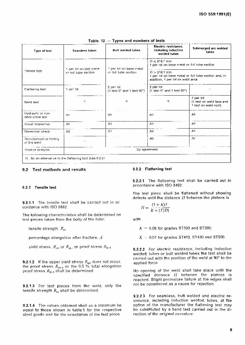
Table 12 - Types and numbers of tests
Type of test
Tensile test
Flattening test
Bend test
Hydraulic or non- destructive test
Visual inspection --
Dimension check
Non-destructive testing of the weld
Product analysis
Searnless tt!beS Butt welded tubes
T
Electric resistance, including induction Submerged arc welded
welded tubes tubes
1 per lot on test piece or full tube sectlon
D < 219,l mm 1 per lot on base metal or full tube section
1 per tot on base metal . or full tube section D > 219,l mm
1 per lot on base metal or full tube section and, in addition, 1 per lot on weld area
-
1 per lot 2 per tot 2 per lot - (1 test 0” and 1 test 90°) (1 test 0” and 1 test 90’)
2 per lot 1) 1) 1) (1 test on weld face and
1 test on weld root) epy-----..
All All All All
__------ All All All All
- All All
/
All All --- - -- ~--
All All -
---------- By agreement
1) As an alternative to the flattening test (see 62.2).
9.2 Test methods and results 9.2.2 Flattening test
9.2.1 Tensile test
9.2.2.1 The flattening test shall be carried out in accordance with ISO 8492.
The test piece shall be flattened without showing defects until the distance H between the platens is
9.2.1.1 The tensile test shall be carried out in ac- cordante with ISO 6892.
The following characteristics shall be determined on test pieces taken from the body of the tube:
rf (l+K)7 - -
K + (T/I>)
with
tensile strength, R,,
percentage elongation after fracture, A
yield stress, R,,, or R,,, or proof stress R,, 5 I
K = 0,09 for grades ST320 and ST360;
K = 0,07 for grades ST410, ST430 and ST500.
9.2.1.2 lf the upper yield stress ReH does not occur, the proof stress Rp02 or the 0,5 % total elongation proof stress Rfo5 shall be determined. !
9.2.2.2 For electric resistance, including induction welded, tubes or butt welded tubes the test shall be carried out with the Position of the weld at 90” to the applied forte.
9.2.1.3 For test pieces from the weld, only the tensile strength R, shall be determined.
No opening of the weld shall take place until the specified distance H between the platens is reached. Slight premature failure at the edges shall not be considered as a Cause for rejection.
9.2.1.4 The values obtained shall as a minimum be equal to those shown in table5 for the respective steel grade and for the orientation of the test piece.
9.2.2.3 For seamless, butt welded and electric re- sistance, including induction welded, tubes, at the Option of the manufacturer the flattening test may be substituted by a bend test carried out in the di- rection of the original curvature.

ISO 559:1991 (E)
9.2.3 Bend test
9.2.3.1 The bend test shall be carried out in ac- cordante with ISO 7438.
9.2.3.2 For seamiess tubes, butt welded tubes and electric resistance, including induction welded, tubes the test piece shall be bent in the direction of the original curvature. For welded tubes the weld shall be positioned at the centre of the test piece. The bend value shall be equal to the value of J-T for the flattening test (see 9.2.2.1).
9.2.3.3 For submerged arc welded tubes, with the exception of tubes in grade ST320, one test piece shall be bent through 180” in the direction of the original curvature (face bend test), and the other in the opposite direction (root bend test), around a mandrel with a diameter eight times the specified thickness of the tube.
9.2.3.4 After the test, the test piece shall not show to the naked eye any Cracks or flaws. However, small premature Cracks at the edges shall not be considered as a Cause for rejection.
9.2.4 Leak tightness test
9.2.4.1 Hydraulic test
Esch tube shall be subjected to a hydraulic test at a pressure PE determined using the following formula:
20ST PE=- v
where S = 60 % of R,, (see table 5).
Unless otherwise agreed, the hydraulic pressure shall not exceed 50 bar (5 MPa). The test pressure shall be maintained for at least 5 s.
Tubes showing Ieakage shall be regarded as not complying with this International Standard.
9.2.4.2 Non-destructive test
The hydraulic test may be replaced, at the Option of the manufacturer, by a non-destructive test carried out as specified in ISO 9302.
9.2.5 Visual inspection
The appearance and soundness of the tubes shall be checked by a visual inspection of the outside and inside surfaces.
9.2.6 Dimension check
The tubes shall be checked for compliance with the outside diameter and thickness specifications.
The thickness shall be checked at the ends of the tubes.
For tubes of outside diameter 1) < 508 mm, the out- side diameter may be checked using a bar gauge or caliper, or by measuring the circumference using a tape.
For tubes of outside diameter 1) > 508 mm, the out- side diameter shall be checked by measuring the circumference using a tape.
9.2.7 Non-destructive test of the weld3)
For all types of welded tube, unless the tube has been submitted to a non-destructive test in place of the hydraulic test according to 9.2.4.1, the weld area shall be submitted to a non-destructive test accord- ing to a suitable technique and procedure at the choice of the manufacturer.
9.3 Invalidation of tests
The specifications given in ISO 404 apply.
9.4 Retest
The specifications given in ISO 404 apply.
IO Marking
10.1 Tubes (uncoated and coated) manufactured in accordance with this International Standard shall be marked, in the sequence given, as follows:
a) the manufacturer’s trade-mark or trade-name;
b) the grade of steel (in accordance with table 3);
c) the number of this International Standard (i.e. ISO 559);
d) W for welded tubes and S for seamless tubes;
and, in addition, for tubes with an inspection certif- icate,
e) the inspector’s mark.
10.2 Coated tubes may require additional marking in accordance with relevant International Standards.
3) The test conditions and the acceptance criteria will be specified at a later date on the basis of studies being carried out by ISOITC 17/SC 19.

ISO 559:1991(E)
11 Lining or coating
All linings and/or coatings shall comply with rel- evant International Standards or with specifications agreed between the purchaser and manufacturer.
NOTE 2 ISO/TC WSC 1 is currently preparing three draft International Standards on
- epoxy powder external coatings,
- cement mortar internal linings.
12 Documents
The documents shall be drafted in accordance with the appropriate clause of ISO 404.
If neither of the documents specified in 4.1, nor any other document as specified in ISO 404, is requested the tubes shall be delivered with a Statement of compliance only.
- polyethylene external coatinqs, and .
11

ISO 559:1991(E)
Annex A (informative)
Schematic representation of the main types of joint
The types of joint shown in this annex are examples; other types are acc,eptabte.
Flange joints should be made in conformity with ISO 7005-2.
Welded joints should be made in conformity with the International Standard,s prepared by ISO/TC 44, Welding.
Figure A.1 - Butt weld
Figure A.2 - Slip-on coupling
Figure A.3 - Sleeve joint
12

ISO 559:1991(E)
Figure A.4 - Sleeve Joint with special end
a) welded neck flange
b) free (lome) flange
c) platt3 fbnge
Figure AS - Flanged joints
Figure A.6 - Joint for tubes with internal coating
NOTE 3 For the connections shown in figureA.3 and figureA.4 the end tan be obtained by preparing the pipe end, by butt welding, or by coupling pieces.
13

ISO 559:1991 (E)
Annex B (informative)
Bibliography
[ TJ ISO 2566-13984, Steel - Conversion of elon- gation values - Part 1: Carbon and low alloy steels.
internal coating by bitumen or coal tar derived ma terials.
[2] ISO 3545-1:1989, Steel tubes and fitfings - Symbols for use in specifkations - Part 1: Tubes and tubular accessories with circular Cross-section.
[4] ISO 6708:1980, Pipe components - Definition of nominal size.
[S] ISOfTR 7003:1990, Unified format for the desig- nation of metals.
[3] ISO 5256:7985, Steel pipes and fittings for bur- [S] ISO 7005-2:1988, Metallic flanges - Part 2: ied or submerged pipe lines - Extemal and Cast iron flanges.
14

This page intentionally left blank

ISO 559:1991(E)
--
UDC 621.643.23:669.14-462
Descriptors: water supply, water pipes, steel tubes, seatnless tubes, welded tubes, specifications, delivery condition.
Price based on 14 pages