. RSRM Top Hat cover :Simulat0r = .: :: ::Lightning Test ... · RSRM Top Hat cover :Simulat0r...
32
. RSRM Top Hat cover :Simulat0r =_.:_::_::Lightning Test Rnal Report ! __:_- _-_: :::_:- VOlume I : : :2 ............. £ : £2: --"--- :: '-_---Nationa3- Ae_dn-abti_ and Space-A_d_inistrati6n ....... - ........... _2=__-:__ George C. Marshall Space Flight Center _ ._mmm_-=: :_:_:: __::_ MarShall SpaceFlight-center,- AJaS-a_n_a 358i2 -- -- ._-_------_ ::=-:: C0ntrau_-N0: .... NAS8-304T)0-_= - - --- :- :- :::---- -_-:-::: :- WBS No: HQ202-10-12 = dl T:._:_--: c---__/__._£_r/CORPORATION _ _ ....... -- _-\ :-: -£ -°: :_- :: -:'T _ :_:-'7.=:_ _ T::_I_-_:2.-:_.T-_-_-_-_ _ - ::__:- : T: ..... :_ < _±= SPA CE OPERATIONS P.O. Box 707, Br/gham City, UT 84302-0707 (801) 863-351 t _f(NASA-C_.-134109) RSRM TOP HAT COVf_ N01-22303 _2--- SIMULAT_ LIGHTNING TEST, Repart (Tniokol Corp.) V_LUME 1 Findl 31 p CSCL 22B Uncles G3/1B 0333_49 I m m https://ntrs.nasa.gov/search.jsp?R=19910012990 2018-07-20T09:21:27+00:00Z
Transcript of . RSRM Top Hat cover :Simulat0r = .: :: ::Lightning Test ... · RSRM Top Hat cover :Simulat0r...

. RSRM Top Hat cover :Simulat0r=_.:_::_::Lightning Test Rnal Report
! __:_- _-_::::_:-VOlume I: : :2 ............. £ : £2:
--"--- :: '-_---Nationa3- Ae_dn-abti_ and Space-A_d_inistrati6n ....... - ...........
_2=__-:__ George C. Marshall Space Flight Center_ ._mmm_-=: :_:_:: __::_ MarShall SpaceFlight-center,- AJaS-a_n_a358i2 --
-- ._-_------_ ::=-::C0ntrau_-N0: .... NAS8-304T)0-_= - - --- :- :- :::----
-_-:-::: :- WBS No: HQ202-10-12
= dl
T:._:_--: c---__/__._£_r/CORPORATION_ _ ....... -- _-\ :-: -£ -°: :_- :: -:'T _ :_:-'7.=:_ _ T::_I_-_:2.-:_.T-_-_-_-_ _ - ::__:- : T: ..... :_ < _±=
SPA CE OPERATIONS
P.O. Box 707, Br/gham City, UT 84302-0707 (801) 863-351 t
_f(NASA-C_.-134109) RSRM TOP HAT COVf_ N01-22303 _2---SIMULAT_ LIGHTNING TEST,
Repart (Tniokol Corp.)
V_LUME 1 Findl
31 p CSCL 22B
UnclesG3/1B 0333_49
I
mm
https://ntrs.nasa.gov/search.jsp?R=19910012990 2018-07-20T09:21:27+00:00Z

"__ CORPORATION
SPACE OPERATIONS
RSRM Top Hat Cover Simulator Lightning Test
Final Test Report
TWR-60834
Volume I
w
Prepared by:
" Test l_Im'In-ingand _eports
Systems Engineer
Approved by:
iTest Planning and Reports
Supervisor
Design En(gineer
,4
]_/ograrn,_i'anager IntegratidnEngineer
SR&QA• " 7 --
]- Data Management
ECS No. SS4156
_7__--_ CORPORATION
SPACE OPERATIONS
ABSTRACT
L
w
L--
m
m
w
m
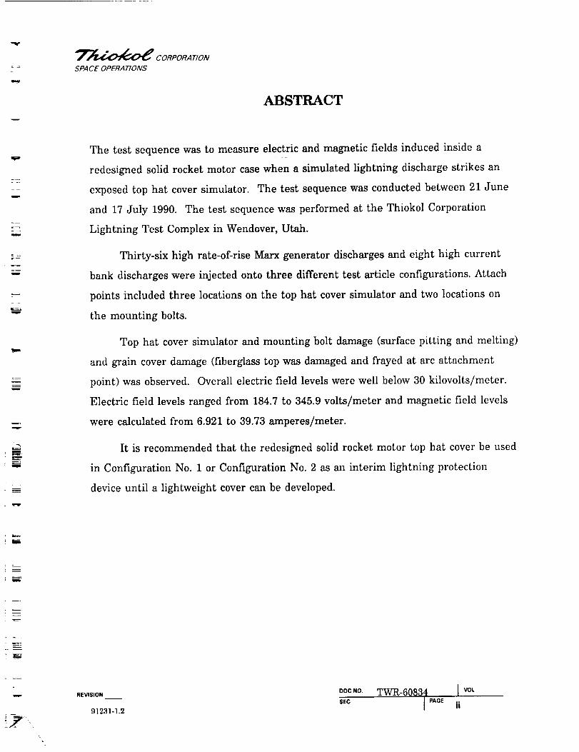
The test sequence was to measure electric and magnetic fields induced inside a
redesigned solid rocket motor case when a simulated lightning discharge strikes an
exposed top hat cover simulator. The test sequence was conducted between 21 June
and 17 July 1990. The Lest sequence was performed at the Thiokol Corporation
Lightning Test Complex in Wendover, Utah.
Thirty-six high rate-of-rise Marx generator discharges and eight high current
bank discharges were injected onto three different test article configurations. Attach
points included three locations on the top hat cover simulator and two locations on
the mounting bolts.
Top hal cover simulator and mounting bolt damage (surface pitting and melting)
and grain cover damage (fiberglass Lop was damaged and frayed at arc attachment
point) was observed. Overall electric field levels were well below 30 kilovolts/meter.
Electric field levels ranged from 184.7 to 345.9 volts/meter and magnetic field levels
were calculated from 6.921 to 39.73 amperes/meter.
It is recommended that the redesigned solid rocket motor top hat cover be used
in Configuration No. 1 or Configuration No. 2 as an interim lightning protection
device until a lightweight cover can be developed.
m
=
- w ,EV,S,ON DOC.0. TWR-60834 I VOL
SEC I PAGE ii
91231-1.2

= _
=_
m
w
m
m
_m
w
w
"_'_ CORPORAT/ON
SPA CE OPERA'/'IONS
CONTENTS
Volume I
Section
1
2
3
4
5
6
7
INTRODUCTION ...................................
1.1 TEST ARTICLE DESCRIPTION ................
OBJECTIVES ......................................
EXECUTIVE SUMMARY .............................
3.1 SUMMARY ................................
3.2 CONCLUSIONS ............................
3.3 RECOMMENDATIONS .......................
INSTRUMENTATION ...............................
PHOTOGRAPHY ...................................
RESULTS AND DISCUSSION .........................
6.1 TEST ARTICLE ASSEMBLY ...................
6.2 SIMULATED LIGHTNING TEST ...............
6.3 TEST ARTICLE INSPECTION AND RESULTS .....
APPLICABLE DOCUMENTS ..........................
Appendix
A
B
Volume II
Resistance Measurements .............................
Lightning Test Data Plots .............................
1
3
9
10
10
11
12
13
14
15
15
17
20
26
Pa e
A
B
REVISION
91231-1.3
DOCNO, TWR-60834SEC
I PAGE
VOL
iii

T__--4_ CORPORA T/ON
SPACE OPERATIONS
FIGURES
1
2
3
4
5
6
7
8
9
10
RSRM Top Hat Cover Simulator Test Article ...............
Worst-Case Model of Lightning Discharge .................
Top Hat Cover Simulator Mounted Onto Test Article ........
Lightning Detector Mounted Onto Test Article .............
Gap Thickness Between Top Hat Cover Simulator
and the Handling Ring ................................
Attach Point Diagram ................................
Surface Pitting Caused by HCB Discharge to Mounting
Bolts and Top Hat Cover Simulator ......................
Surface Pitting Inflicted Upon Top Hat Cover Simulator ......
Carbon Spot on Grain Cover Proving Unwanted
Arcing Occurred ....................................
Damage to Grain Cover After Subjection to
Marx Discharge ....................................
2
4
6
8
16
18
21
22
24
25
ml
u
w
Rw
!m
Tabl_____e
1
2
TABLES
Total Discharges ....................................
Configuration Test Sequence ..........................
5
19
E
REVISION
91231-1.4
oocNo, TWR-60834 [ vo,
SEC I PAGE iv

w
W
w
m.
w
_"_V-__ CORPORATION
SPA CE OPERATIONS
1
INTRODUCTION
This report documents the procedures, performance, and results obtained from the
evaluation of simulated lightning discharges to an RSRM test article. The test
sequence was conducted following WTP-0245, Rev A. There were three purposes of
this test.
a. Measure the electric field levels inside the redesigned solid rocket motor (RSRM)
case when a simulated lightning discharge is injected onto the top of the test
article. The fields should not exceed 30 kilovolts per meter (kV/m) (1/10 the
dielectric breakdown of the propellant) inside the case.
b. Determine if any arcing occurs between the case, handling ring, grain cover,
segmented ring, or top hat cover simulator.
c. Evaluate methods of detecting a lightning attachment to a segment while in the
vertical transportation mode at Kennedy Space Center (KSC).
This test sequence was accomplished by injecting simulated lightning discharges
onto a top hat cover simulator, mounting bolts, and a grain cover, and then evaluating
the measured electric fields and calculated magnetic fields inside the empty RSRM
case.
The test article was placed between two horizontal grids of a peaking capacitor
(Figure 1). The peaking capacitor has a 9-m distance between two parallel grids. The
two parallel 2,500-m 2 wire grids (upper and lower) make up two plates of a 2.5-nano-
farad (nF) capacitor.
The Marx generator discharges were by direct arc attachment to the top hat
cover simulator, the mounting bolts, and the grain cover. The Marx discharges
_EV,S,ON OOCNO TWR-60834 I voL
SEC I PAGE 191231-1.5

-,,,-i
= ,
w i
7
w
w
m
W
m
l
m
m
w
w
ww
"7"_ CORPORA T/ON
SPA CE OPERA TIONSORIGINAL PAGE
BLACK AND WHITE PHOTOGI_APH Nl18337-27
i ' i
!
ii |
i
REVISION DOCNO. TWR-60834 VOL
SECI PAGE 2
==i-
3==
=>
-i-
¢/)
,.J
==
.mU.

. =
V
m
w
m
v
E
mw
T_ CORPORAT/ON
SPA CE OPERATIONS
simulated the fast rise in current with respect to time of a worst-case lightning
discharge to unprotected flight hardware on the ground (Figure 2, points A - B), as
defined in NSTS 07636, Rev D.
The high current bank (HCB) simulated lightning discharges were by direct arc
attachment to the top hat cover simulator and the mounting bolts. The HCB
simulated the peak current of a worst-case lightning discharge to unprotected flight
hardware on the ground (Figure 2, points B - C), as defined in NSTS 07636, Rev D.
The test sequence was completed on 17 July 1990. Simulated lightning
discharge testing was performed at the Thiokol Corporation Lightning Test Complex
in Wendover, Utah. Testing complied with JSC 20007 and NSTS 07636, Rev D. This
test was part of an ongoing lightning test program to evaluate the effects of lightning
strikes on the complete RSRM and Space Transportation System.
1.1 TEST ARTICLE DESCRIPTION
All hardware components used in the test article configurations are included in this
test article description except those that had no effect on the results. Deviations
from the configurations listed in WTP-0245, Rev A, were approved by the Integration
Engineer and Program Manager. Three test article configurations were tested using
the Marx generator and the HCB. Table 1 indicates the number of discharges per
configuration and the total number of discharges for each current bank.
m
D
iR
w
REVISION DOCNO, TWR-60834 I VOL
SEC I PAGE 391231-1.6

w
m
m
w
m
_'_ CORPORATION
SPACE OPERATIONS
Q.
o
C)
._E
E
--,E
0(I)
,_-:t0
<
r-0
C
r-
_1
0
"130
¢1)
I
0
e_
REVISION ooc NO. TWR-60834 ] vo,
SEC 1 PAGE 4

w
w
i
i
v
_"_ CORPORATION
SPACE OPERATIONS
Table I. Total Discharges
Number of Discharges
Configuration No. Marx Current Bank High Current Bank
2 26 3
43 6
4 4
36Total
1
8_, r
Configuration No. 1 listed in WTP-0245, Rev A, was not used because of warping
during the manufacturing of the top hat simulator. This warping prevented the top
hat simulator from making complete contact with the handling ring when all of the
bolts were installed. Configurations No. 2 and 3 were considered worst-case situations.
The rationale was that if the worst-case configuration could survive the test, then the
nominal configuration could survive the test. The fourth configuration listed in this
document was not listed in WTP-0245, Rev A, but was added to the test sequence for
evaluation purposes.
1.1.1 Configuration No. 2
Test article Configuration No. 2 consisted of a test stand placed on the lower capacitor
grid with an empty RSRM case segment (1U50715-02) mounted vertically. Installed
around the top edge of the case was a handling ring (8U50943-03), grain cover
(8U75816-01), and segmented ring (8U50929-03). Mounted above the grain cover onto
the handling ring was a top hat cover simulator (Figure 3). WTP-0245 Configuration
No. 2 calls for 0.25-in. shims to be placed between the top hat simulator and the
handling ring, which was intended to simulate warping of the cover. During the
manufacturing process the top hat simulator warped making the use of shims
unnecessary.
.eVlSlON OOCNO. TWR-60834 ] vo,
SEC I PAGE 591231-1.7

l
w
t
v
=
.i=
w
m
=
=i
W
i=
T_ CORPORATION
SPACEOPERAT/ONS ORtGINAE PAGE
BLACK AND WHITE PHOTOGRAPHNl18337-28
.9
o
o
o
E
oO
"1-
ob-
¢6
REVISION DOC NO, TWR-60834
SECI PAGE
I VOL

.
w
m
w
m
m=
i
m
m
w
SPACE OPERA T]O/VS
Four lightning detectors (8U76447) were mounted to the case (Figure 4) using a
piece of polystyrene foam and olive drab waterproof tape (Permacel No. P672, Thiokol
Corporation Stock No. 57-742061). Two of the detectors had sensitivities less than
500 amperes per meter (A/m), and the other two detectors had sensitivities greater
than 500 A/m. The detectors were installed for detection 500 A/m during a Marx
discharge to the test article.
1.1.2 Configuration No. 3
The next test article configuration consisted of a test stand placed on the lower
capacitor grid with an empty RSRM case segment (1U50715-02) mounted vertically.
Installed around the top edge of the case was a handling ring (8U50943-03) and
segmented ring (8U50929-03). Mounted onto the handling ring was a top hat cover
simulator. Non-conductive shims (0.25-in. thick) were to be installed between the
handling ring and the top hat cover simulator. However, due to warping during the
top hat simulator manufacturing process, shims were not needed or installed. The
grain cover was not used.
1.1.3 Configuration No, 4
This test article configuration consisted of a test stand placed on the lower capacitor
grid with an empty RSRM case segment (1U50715-02) mounted vertically. Installed
around the top edge of the case was a handling ring (8U50943-03), grain cover
(8U75816-01), and segmented ring (8U50929-03). The top hat cover simulator was not
installed; only the grain cover was used.
=
r
m
w
_mR
REV,S,ON OOCNO. TWR-60834 I voLSEC I PAGE 7
91231-1,8

m
__=7
m
T
z
m
m
B
_m
"_"_ CORPORA T/ON
SPA CE OPERATIONS ORIGINAL PAGE
BLACK AND WHITE PHOTOGRAPHN[18337-5
O
c-O
O
1:;
c-
e-
_J
M.
mFREVISION
DOC NO.
SEC
TWR-60834 I VOL
I PAGE 8

T_ CORPORA T/ON
SPACE OPERATIONS
2
OBJECTIVES
The objectives of Test Plan WTP-0245 were:
A. Verify that the induced electromagnetic field levels are less than 30 kV/m when
the test article is subjected to a simulated lightning discharge.
B° Verify that no arcing occurs between the case, handling ring, grain cover, or top
hat cover simulator when subjected to a simulated lightning discharge.
C. Evaluate methods of detecting a lightning discharge to the RSRM.
i
m
w
W
--==
m
w
I
m
i
i REVISION DOCNO TWR-60834 I VOL
$EC I PAGE 9
91231-1.9

"_""J_0"1_ CORPORATION
SPA CE OPERATIONS
3
EXECUTIVE SUMMARY
3.1 SUMMARY
Additional information and details can be found in Section 6 (Results and Discussion).
A total of 36 Marx generator discharges were conducted. A total of eight HCB
discharges were conducted. A total of 44 lightning current discharges were made
during this test sequence.
The HCB was charged to approximately 36,000 V for each discharge, which
resulted in peak currents of approximately 1.75 x 10⁵ amperes (A). The Marx
generator was charged to approximately 20,000 V for each discharge, which resulted in
peak rise rates of approximately 1.4 x 10¹¹ amperes per second (A/s). The highest
rise rate for the Marx generator was 3.9 x 10 zz A/s.
None of the discharges resulted in an electric field larger than 345.9 V/m. The
largest magnetic field calculated from the surface current data was 39.73 A/m. The
data indicates that the electric field levels measured inside the test article are below
the limit of 30 kV/m in all configurations. The measured electric field levels were not
strong enough to cause dielectric breakdown of the propellant.
The photographic documentation indicates that Configuration No. 2 provides
the necessary arcing protection between the test article hardware components.
Configurations No. 3 and 4 showed evidence of arcing. Top hat cover simulator and
mounting bolt damage (surface pitting and melting) and grain cover damage (fiberglass
top damaged and frayed at arc attachment point) was observed.
Two lightning detectors with sensitivities less than 500 A/m detected induced
current on the case from a Marx discharge. Two lightning detectors with sensitivities
E
rEVISION OOCNO TWR-60834 ] vot
SEC ]PAGE 1091231-1.10

m
m_
r
m
===i
m._
m
m
w
T__--_ CORPORAT/OA/
SPA CE OPERATIONS
greater than 500 A/m did not detect the simulated lightning currents from the Marx
discharge. The lightning detector performance indicates that the more-sensitive
lightning detectors are adequate to detect surface currents induced by the fast rising
current portion of the worst-case lightning discharge.
3.2 CONCLUSIONS
The following is a list of conclusions as they relate specifically to the objectives.
Additional information about the conclusions can be found in Section (Results and
Discussion).
Obj ectives Conclusions
A° Verify that the induced
electromagnetic field levels are
less than 30 kV/m when the test
article is subjected to a simulated
lightning discharge.
Verified. The electric field levels and
magnetic field levels were well below
the limit. The largest measured
electric field being 345.9 V.
So Verify that no arcing occurs
between the case, the handling
ring, the grain cover, or the top
hat cover simulator when
subjected to a simulated lightning
discharge.
Partially Verified. No arcing was
detected between any of the hardware
components in Configuration No. 2.
Photographic documentation was used
to verify this conclusion.
In Configuration No. 2 no arcing was
detected between the top hat cover
simulator and the handling ring
during the Marx attachments.
During the HCB attachments, arcing
was detected between the handling
ring and the top hat cover simulator.
Arcing was detected between the
grain cover and handling ring in
Configuration No. 4. Photographic
documentation was used to verifythese conclusions.
m
REVISION
91231-I.11
ooc ,o TWR-60834 I vocSEC
j PAGE 1 1

z
z
F
m
w
m,
miM
m
_F.-_ CORPORAT/ON
SPA CE OPERATIONS
C.
Objectives
Evaluate methods of detecting a
lightning discharge to the RSRM.
Conclusions
Evaluated. Two detectors with
sensitivities less than 500 A/m
detected the simulated lightning
discharge indicating that thesedetectors can detect the case surface
currents induced from the Marx
generator.
Two lightning detectors with
sensitivities greater than 500 A/m did
not detect the case surface currents
induced by the Marx generator.
3.3 RECOMMENDATIONS
3.3.1 Electromagnetic Fields
No further testing is recommended to determine electric field levels induced within
the test article. The levels measured were 1/100 the objective limit (1/1000 of the
dielectric breakdown point of the RSRM propellant).
3.3.2
Additional testing, to determine if arcing between hardware components occurs, is not
recommended. Test article Configuration No. 2 survived 26 Marx discharges and four
HCB discharges with no arcing. This indicates that this configuration provides
adequate arcing protection between hardware components.
3.3.3 Lightning Detectors
The lightning detectors presently being used to monitor railcar shipments are
adequate for the detection of a lightning strike to a segment and should be used for
this purpose. However, additional testing with a goal to develop a more practical
method of detecting a lightning strike should continue.
m
REVISION DOCNO, TWR-60834 [ vo,
SEC JPAaE 1291231-1.12

L--
V
_'_ CORPORATION
SPACE OPERATIONS
4
INSTRUMENTATION
Instrumentation used during this test was a Nanofast Electric Field Sensor (model No.
EFS1) and two magnetic flux density derivative sensors, EG&G model MGLS5A (B dot
sensors). The electric field sensor was calibrated by the manufacturer on 29 June
1990. The B dot sensor was calibrated by the manufacturer before being purchased in
1987, and did not require any new calibrations.
F
m
i
B
B
w
z
m
iooc _o. TWR-60834 i VOL
REVISION ]
sEc I PAaE1391231-1.13

= :
v
T_ CORPORATION
SPACE OPERATIONS
5
PHOTOGRAPHY
Still color photographs were taken of the test article assembly and during the
simulated lightning discharges. Copies of the photographs (Series 118336, 118337,
118338, 118339, 118340, and 118476) are available from the Thiokol Photographic
Services department.
m
!
=
l
m
m
!
w
W
E
_EVlSION OOC,o TWR-60834 I vOL
SEC I PAGE1491231-1.14

'_'_ CORPORATION
SPACE OPERATIONS
6
RESULTS AND DISCUSSION
F=_
V
w
,IN
m
E
.___.
m
6.1 TEST ARTICLE ASSEMBLY
The test article was configured three different ways. Each configuration is detailed in
the following sections.
6.1.1 Configuration No. 2
The RSRM top hat cover simulator test article was assembled per WTP-0245, Rev A.
This configuration consisted of a test stand placed on the lower parallel peaking
capacitor grid, an empty RSRM segment mounted vertically on the test stand, a
segmented ring, a handling ring, a grain cover, and a top hat cover simulator. Due to
warping there was a gap in excess of 0.25 in., so the nonconductive shims were not
used.
6.1.2 Configuration No. 3
This configuration consisted of a test stand placed on the lower parallel peaking
capacitor grid, an empty RSRM segment mounted vertically on the test stand, a
segmented ring, a handling ring and a top hat cover simulator. This configuration did
not include the grain cover. The 0.25-in. shims were not installed between the top
hat cover simulator and the handling ring. The shims were not installed because the
gap between the top hat cover simulator and the handling ring was a minimum of
0.25 in. at several locations around the circumference of the test article (Figure 5).
6.1.3 Configuration No. 4
This configuration consisted of a test stand placed on the lower parallel plate peaking
capacitor grid, an empty RSRM segment mounted vertically on the test stand, a
m
m
m
REVISION__ DOCNO. TWR-60834 ] voLSEC J PAGE 1591231-l.15

iI
V
m
w=
I
w
i
r
W
I
=
J
_"_ CORPORATION
SPACE OPERATIONS ORIGINAL PAGE
BLACK AND WHITE PHOTOGRAPHNl18337-33
REVISION DOCNO. TWR-60834 I VOL
SECI PAGE 16
01r-
ii
o1r-
i
"10r,.
"I-
ra
,-I
E,i
or)I,,,
0(J
"I-
O,.0
I--
r-G)
rn
¢/)
G)
iF--Iz
(3
.=
I.I.

w
_F"__--A_ CORPORATION
SPACE OPERATIONS
segmented ring,a handling ring,and a grain cover.
the top hat cover simulator.
This configuration did not include
w
w
im-i J"
w
m
W
!L
!
6.2 SIMULATED LIGHTNING TEST
6.2.1 Discharge Locations/Modes
The discharge down-conductor was positioned on the top of each test article
configuration in the following five locations (Figure 6).
Location No. 1: At 1-ft radial distance in from the RSRM case edge
Location No. 2: On the mounting bolt at 0 deg
Location No. 3: At 2-ft radial distance from the centerline of the RSRM case
Location No. 4: At the RSRM case centerline position
Location No. 5: On the mounting bolt at 180 deg
A total of 36 Marx generator discharges were conducted. A total of eight HCB
discharges were conducted. A total of 44 electrical current discharges were conducted
during this test sequence.
The discharge down-conductor was positioned on the top hat cover simulator,
the mounting bolts, and the grain cover (Figure 6). The Marx generator was charged
to approximately 26,000 V for each discharge, which resulted in peak current rise
rates of 2 x 10¹¹ A/s.
The discharge down-conductor was positioned on the top hat cover simulator,
the mounting bolts, and the grain cover (Figure 6). The HCB was charged to 36,000
V (for most shots) and 45,000 V (for one shot) for each discharge, resulting in peak
currents of approximately 175,000 to 200,000 A. Action integrals of the discharges
were approximately 2 x 10⁶ (A2).
6.2.2 Test Sequence
Table 2 identifies each set of discharges with respect to each configuration.
REV,S,ON _OCNO TWR-60834 I VOL
SEC I PAGE 17
91231-1.16

T__--4_ CORPORA T/O,V
SPA CE OPERA TIO,_S
I
i
m
m
W
m
180 deg
t//
/
I
Location \
No. 5 \\
270 deg
\X
X
/t
//
90 deg
Top View of Test Article
Bolt With
Flat Washer
Figure 6. Attach Point Diagram
LocationNo. 4
LocationNo. 3
0 deg
LocationNo. 1
LocationNo. 2
AC29C63a
!
mW
REVISIONDOC NO
SEC
3_V£,.-60834 i VOt
I
J PAGE
18

w
m
m
m
r
r
rE
_P'__--_ CORPORA TION
SPA CE OPERA TIONS
Table 2. Configuration Test Sequence
Discharge Set No.
Configuration No. Marx Current Bank High Current Bank
2 26 3
4 0 1
3 6 2
4 4 0
3 0 2
There were 26 Marx discharges and three HCB discharges injected onto the test
article in Configuration No. 2 for a total of 29 discharges. The simulated lightning
injection waveform and the interior electric field were measured. The interior
magnetic field was calculated.
Following the testing in Configuration No. 2, the test article was configured
with only the handling rings and grain cover installed. This was to allow the testing
of the present handling configuration, which had never been done. Two shots were
attempted, but only the first was successful. Since the field sensor had been dropped
and damaged previously, only the magnetic field data were collected on this shot.
After the discharges were completed for Configuration No. 4, the test article
was assembled to Configuration No. 3. In this configuration six Marx discharges and
two HCB discharges were injected onto the test article before the HCB was damaged.
The test article was assembled to Configuration No. 4. A total of four Marx
discharges were injected onto the test article in this configuration and one HCB.
The test article was reassembled to Configuration No. 3. When the test article
and the HCB were ready for testing, two HCB discharges were injected onto the test
,Ev,s,o, ooc No TWR-60834 ] voL
sEc J PAGE1991231-1.17

Tb,._"
= =
w
_W
m
_F-_ CORPORATION
SPACE OPERATIONS
The test article was reassembled to Configuration No. 3. When the test article
and the HCB were ready for testing, two HCB discharges were injected onto the test
article completing the RSRM top hat cover simulator lightning test.
6.2.2 Data Recovery
Data plots of the injected waveforms, the derivative of the injected waveforms (Marx
attachments only), the interior electric fields, and the interior magnetic fields were
made, following each strike (Volume II).
Of the 44 electrical current discharges conducted, the electric field
measurements during the first eight discharges failed because the fiber optic data
transmission line was disconnected to the data acquisition system. During discharges
No. 15 through No. 29 an analog integrator was installed on the B dot sensor fiber
optic transmission line. It was discovered after looking at the data that the integrator
was faulty. The data were unrecoverable and cannot be used for analysis.
6.3 TEST ARTICLE INSPECTION AND RESULTS
6.3.1 Electromagnetic Fields
None of the discharges resulted in electric fields exceeding the 30 kV/m objective.
The electric field levels were approximately 1,000 times lower than the dielectric
breakdown level of th.e RSRM propellant and approximately 100 times lower than the
30-kV/m objective level specified in WTP-0245, Rev A_ Magnetic field levels were 10
times lower than the electric field levels.
6.3.2 Arcin_
Arcing was observed between hardware components in Configurations No. 2 and No. 3.
Arcing was observed between the handling ring and top hat cover simulator in
Configuration No. 3 during the last two HCB discharges. Top hat cover simulator and
mounting bolt damage (surface scorching, pitting, and melting) was observed
(Figures 7 and 8).
REVISIONoocNO. TWR-60834 I vo,
SEC I PAGE20

_=_
r
E,
!
m
c
F
_F--_ CORPORATION
SPA CE OPERAT/ONS ORIGINAL PAGE
BLACK AND WHITE PHOTOGi_APH N118476-5
__.
8.1-o.
"0
0g}
¢,-
0
o
¢,-
._=amL).I-
.Q
U
O.
o
o_
L_
._mLI.
t_
REVISIONooc No TWR-60884 I voL
SEC ]PAOE 21

w
w
"7-_ CORPORAT/ON
SPA CE OPERA TIONS
REVISION
ORIGINAL PAGE
BLACK AND WHITE PHOTOGRAPH
N118340-4
1
lm
oocNo. TWR-60834 J VOL
SECI PAGE 22

w
__ CORPORATION
SPA CE OPERATIONS
Arcing was observed between the grain cover and the handling ring during the
HCB discharges injected onto the test article in Configuration No. 4 (Figure 9).
Damage to the grain cover is shown in Figure 10. During HCB discharges injected
directly to the grain cover, the fiberglass top was damaged and frayed at the arc
attachment point.
6.3.3 Li_htnin_ Detectors
Two detectors with sensitivities less than 500 A/m detected the simulated lightning
discharge indicating that these detectors can detect the case surface currents induced
from the Marx generator.
Two lightning detectors with sensitivities greater than 500 A/m did not detect
the case surface currents induced by the Marx generator.
w
E_
m=._!
w
.EV,S,O. OOCNo. TWR-60834 I vo.
SEC I PAGE 23

= ,
_w
==__
w
w
v
.===
h_
F_
w
H
m
u
=
"_7"_ CORPORATION
SPACE OPERATIONS
ORIGINAL PAGE
BLACK AND WHITE PHOTOGI_APH N118337-17
REVISION vocNO. TWR-60834 I VOL
SEC
==
<_
0,.
>U
¢-
(3
¢:0
e-o£
U
U.

_..==--.
W
m
_r_
E
W
r_
Em
W_.
_k
"_'_ CORPORATION
SPA CE OPERATIONSORIGINAL PAGE
BLACK AND WHITE PHOTOGRAPH
Nl18337-15
a)
IBr-u
inu-r
C0
G)
(/)
I._
00
m(.90
q)
(5
I_
i1
REVISION ooc NO. TWR-60834 I vo,SEC

W
m
m
w
m
T_ CORPORA T!ON
SPA CE OPERATIONS
Document No.
NSTS 07636 Rev D
JSC 20007
WTP-0245
STW7-500
Drawing No.
7
APPLICABLE DOCUMENTS
Titl...___e
Lightning Protection Criteria Document
Lightning Protection Verification Document
RSRM Top Hat Cover Simulator Lightning Test Plan
Marking Methods, Identification
D
E
w
8U76447
8U5O943
8U5O929
1U5O715
8U5O816
Sensor--Magnetic Field, Passive
Handling Ring--Solid Rocket Motor
Ring, Segmented, Clevis Joint, Rocket Motor
Case Segment, Stiffener--Lightweight
Tie-Down Assembly, Cover Assembly--Railcar, Heavy Duty
E
mw
i
W
REVISION
91231-1.20
DocNo TWR-60834 j vo,
sec I PAGe 26

w
um_
U
"_"_ CORPORATION
SPACE OPERATIONS
._-'ne
R. Danforth
N. Black
B. Whidden
J. Griffin
P. St Jean
J. Godfrey
L. Abrahamson
K. Sanofsky
R. Larsen
F. Duersch
R. Papasian
M. Fisher
Print Crib
Data Management
Distribution List
L71
L71
L62A
L62A
L62A
E06
E80
851
851
851
E05
K68 (USBI)
Q51B1
L74B
No. Copies
1
1
1
1
1
1
1
1
1
1
45
5
5
5
==_=
w
z
REVISION
91231-1.21
ooc No TWR-60834 I voL
SEC [ PAGE