- PIC-Gen... · used function generator was the 8038, manufactured by various companies under...
11
Copyright © 2008, Wimborne Publishing Ltd (Sequoia House, 398a Ringwood Road, Ferndown, Dorset BH22 9AU, UK) and TechBites Interactive Inc., (PO Box 857, Madison, Alabama 35758, USA) All rights reserved. The materials and works contained within EPE Online — which are made available by Wimborne Publishing Ltd and TechBites Interactive Inc — are copyrighted. TechBites Interactive Inc and Wimborne Publishing Ltd have used their best efforts in preparing these materials and works. However, TechBites Interactive Inc and Wimborne Publishing Ltd make no warranties of any kind, expressed or implied, with regard to the documentation or data contained herein, and specifically disclaim, without limitation, any implied warranties of merchantability and fitness for a particular purpose. Because of possible variances in the quality and condition of materials and workmanship used by readers, EPE Online, its publishers and agents disclaim any responsibility for the safe and proper functioning of reader‐constructed projects based on or from information published in these materials and works. In no event shall TechBites Interactive Inc or Wimborne Publishing Ltd be responsible or liable for any loss of profit or any other commercial damages, including but not limited to special, incidental, consequential, or any other damages in connection with or arising out of furnishing, performance, or use of these materials and works. READERS’ TECHNICAL ENQUIRIES We are unable to offer any advice on the use, purchase, repair or modification of commercial equipment or the incorporation or modification of designs published in the magazine. We regret that we cannot provide data or answer queries on articles or projects that are more than five years’ old. We are not able to answer technical queries on the phone. PROJECTS AND CIRCUITS All reasonable precautions are taken to ensure that the advice and data given to readers is reliable. We cannot, however, guarantee it and we cannot accept legal responsibility for it. A number of projects and circuits published in EPE employ voltages that can be lethal. You should not build, test, modify or renovate any item of mains‐powered equipment unless you fully understand the safety aspects involved and you use an RCD adaptor. COMPONENT SUPPLIES We do not supply electronic components or kits for building the projects featured; these can be supplied by advertisers in our publication Practical Everyday Electronics. Our web site is located at www.epemag.com We advise readers to check that all parts are still available before commencing any project. To order you copy for only $18.95 for 12 issues go to www.epemag.com www.epemag.com
Transcript of - PIC-Gen... · used function generator was the 8038, manufactured by various companies under...

Copyright © 2008, Wimborne Publishing Ltd (Sequoia House, 398a Ringwood Road, Ferndown, Dorset BH22 9AU, UK)
and TechBites Interactive Inc., (PO Box 857, Madison, Alabama 35758, USA)
All rights reserved.
The materials and works contained within EPE Online — which are made available by
Wimborne Publishing Ltd and TechBites Interactive Inc — are copyrighted. TechBites Interactive Inc and Wimborne Publishing Ltd have used their best efforts in preparing these materials and works. However, TechBites Interactive Inc and Wimborne Publishing Ltd make no warranties of any kind, expressed or implied, with regard to the documentation or data contained herein, and specifically disclaim, without limitation, any implied warranties of merchantability and fitness for a particular purpose. Because of possible variances in the quality and condition of materials and workmanship used by readers, EPE Online, its publishers and agents disclaim any responsibility for the safe and proper functioning of reader‐constructed projects based on or from information published in these materials and works. In no event shall TechBites Interactive Inc or Wimborne Publishing Ltd be responsible or liable for any loss of profit or any other commercial damages, including but not limited to special, incidental, consequential, or any other damages in connection with or arising out of furnishing, performance, or use of these materials and works. READERS’ TECHNICAL ENQUIRIES
We are unable to offer any advice on the use, purchase, repair or modification of commercial equipment or the incorporation or modification of designs published in the magazine. We regret that we cannot provide data or answer queries on articles or projects that are more than five years’ old. We are not able to answer technical queries on the phone.
PROJECTS AND CIRCUITS
All reasonable precautions are taken to ensure that the advice and data given to readers is reliable. We cannot, however, guarantee it and we cannot accept legal responsibility for it. A number of projects and circuits published in EPE employ voltages that can be lethal. You should not build, test, modify or renovate any item of mains‐powered equipment unless you fully understand the safety aspects involved and you use an RCD adaptor.
COMPONENT SUPPLIES
We do not supply electronic components or kits for building the projects featured; these can be supplied by advertisers in our publication Practical Everyday Electronics. Our web site is located at www.epemag.com
We advise readers to check that all parts are still available before commencing any project.
To order you copy for only $18.95 for 12 issues go to www.epemag.com
www.epem
ag.co
m

Copyright © 2000 Wimborne Publishing Ltd andMaxfield & Montrose Interactive Inc
EPE Online, July 2000 - www.epemag.com - 518
Combining the sophisticatedfeatures of a Maxim MAX038waveform generator and aPIC16F877 microcontroller hasresulted in a highly versatile andinexpensive workshop tool whosefacilities have hitherto beenunattainable without considerabledesign complexity.
The MAX038 is a high-frequency precision functiongenerator whose output isselectable to produce triangle,sine and square waveforms,within a wide operating frequencyspan of 0����1Hz to over 10MHz, splitin the PIC-Gen as eightoverlapping frequency ranges.Range and waveform selectionare performed by the PIC16F877in response to pushbutton switchcontrols. Frequency is fullyvariable within the selected rangeby means of a front panel controlpotentiometer.
An alphanumeric liquid crystalmodule displays the frequencyand range information.
Four frequency outputs areprovided:
o) Direct output at �1V peak-to-peak
o) AC coupled output, fullyvariable between zero and4V peak-to-peak
o) Pulse output, 0V to 5Vlogic level
o) 3����2768MHz fixedfrequency, 0V to 5V logiclevel
Prior to the introduction ofthe MAX038, arguably the maincontender for the most widelyused function generator was the8038, manufactured by variouscompanies under different prefixcodings, such as ICL8038 andXR8038, for instance.
The 8038 is still widely usedbut it has limitations in themaximum frequency that can begenerated. The range is typically0����001Hz to 100kHz.
The MAX038, however, isstated to have an upperfrequency limit of at least20MHz, and possibly around40MHz. It has to be said,though, that attaining such highfrequencies requires printedcircuit board design andconstruction techniquesnormally found only incommercial manufacturingestablishments.
The upper frequency limit ofthe device is dependent not onlyon very accurate control of thecurrent flowing into its frequencysetting inputs, but also on thecapacitance associated withthem. Maxim state in their datasheet, for instance, that the
Add even more versatility to your workshop facilities.
PIC-GEN FREQUENCY GENERATOR/COUNTER by JOHN BECKER
The PIC is also used as afrequency counter, switchselectable to monitor thefrequency generated by theMAX038, or from an externalsource in conjunction with a pre-conditioning waveform shaperand frequency divider. Twoexternal signal inputs areprovided: one for 0V to 5V logiclevel waveforms, the other forAC waveforms having a peak-to-peak swing of between about2V to 5V. The prototype canmonitor frequencies in excess of40MHz.
MAX038 FUNCTIONGENERATOR
In EPE September ’96,Andy Flind first introducedreaders to the merits of the thennewly introduced MAX038waveform generator, in a specialfeature article of the samename. He followed it up with afull constructional article, the10MHz Function Generator, inOctober ’96.
www.epem
ag.co
m

Copyright © 2000 Wimborne Publishing Ltd andMaxfield & Montrose Interactive Inc
EPE Online, July 2000 - www.epemag.com - 519
specified upper frequency limitis achieved when the timingcapacitance is less than orequal to 15pF and the controlcurrent is 500uA.
Unfortunately, on a PCBdesigned for successfulassembly by the averagehobbyist, the capacitancebetween the MAX038, othercomponents and the tracks islikely to prevent the maximumfrequency from being reached.The prototype PIC-Gendescribed here achieves amaximum of just over 10MHz.
PIC-GEN CONCEPTConsidering how the
MAX038 might be put undersemi-automatic control as partof a frequency generator andcounter system, the authorrecognized that a PIC16F877microcontroller might providethe key. This device has fiveinput-output ports which, itseemed, could possibly provideautomated switching of thefrequency range capacitors,selection of the waveformshape, offer frequency countingand provide an output to a liquidcrystal display.
Doing a basic mock-up onstripboard coupled to a PICroughly programmed to performthe bare essentials proved theviability of the idea. The conceptwas then given full flesh andbones to become the designwhose circuit diagram is given inFig.1.
The MAX038 functiongenerator is shown as IC2. It willbe seen that half the pins aregrounded and from some oftheir notations it will probably be(correctly) deduced that thedevice has more functions thanare used here. For informationabout the device’s full range offunctions, see its data sheet(details later) or Andy Flind’s
Sept/Oct ’96 articles.In the PIC-Gen design, the
controls used are those that setfrequency and waveform shape.The eight frequency ranges areset according to the capacitancevalue connected to the device’sC OSC pin. Fine tuning of thefrequency is performed byvarying the current provided bypotentiometer VR1 to the I INpin.
Resistor R2 limits themaximum current that can flow,while R1 sets the minimumcurrent.
FREQUENCYSELECTION
Eight capacitors are used toset the frequency ranges, C11 toC18. These are commonlyconnected at one end to the COSC pin (5). Capacitors C12 toC18 have their other endsconnected individually to portpins of the PIC microcontroller,IC5. For PCB layoutconvenience these pins werechosen to be RB1 to RB5, RD6and RD7. Capacitor C11 ispermanently connected to the0V line.
Normally, the above sevenpins are set as inputs to the PIC.In this condition, they areeffectively held in an open-circuitstate, the PIC inputs having avery high impedance. As such,the MAX038 ignores thosecapacitors.
To bring one of the sevenport controlled capacitors intocircuit, the PIC has theappropriate pin set as an outputheld at logic 0 (0V). With ahigher capacitance valueselected, so the lower the outputfrequency from IC2.
For the highest frequencyrange, capacitor C11 is thecontrolling component. Note,though, that its nominal value of
10pF will be seen by the MAX038as a value higher than this due tothe (unpredictable) capacitance ofthe circuit in proximity to the COSC pin. Capacitor C11 could beomitted if you want to tryincreasing the maximumfrequency attainable.
Pushbutton switches S1 andS2 cause the PIC to step thefrequency range down or up(respectively) on a continuous 8-step loop.
Nominally, the capacitorvalues have been chosen toprovide a factor of ten differencebetween each step. Normalmanufacturing tolerances apply tothese values, especially with theelectrolytic capacitors.
Potentiometer VR1 provides afrequency control range of about 1to 50. For example, if theminimum current flow throughVR1 and R2 causes a frequencyof 1kHz, then maximum currentflow will cause 50kHz to begenerated. The range may beshortened by increasing the valueof R1, although this will raise thelowest frequency that can beattained.
WAVEFORMSELECTION
PIC-Gen provides selection ofthree waveform shapes, Sine,Triangle and Square.
Selection is made accordingto the binary code placed on theMAX038’s A0 and A1 inputs. Thecode is controlled by the PIC, viaits RB6 and RB7 pins, as follows:
A1 A0 WAVEFORM0 0 Square0 1 Triangle1 x Sinewhere x = don’t care
Pushbutton switch S4 causesthe PIC to step through the threewaveform codes on a repeating
Constructional Project
www.epem
ag.co
m
Copyright © 2000 Wimborne Publishing Ltd andMaxfield & Montrose Interactive Inc
EPE Online, July 2000 - www.epemag.com - 520
cycle.The selected waveform is
output at IC2 pin OUT and has afixed amplitude of �1V,symmetrical about 0V. Theoutput has a very lowimpedance (typically 0����1�) andcan be used directly via socketSK5.
The same waveform isamplified by the non-invertingopamp circuit around IC3a. Thegain is set at x2, resulting in anoutput swing of �2V. CapacitorC3 provides DC isolation of theoutput and potentiometer VR2provides full control over theamplitude output at socket SK3,from zero to maximum.
It should be noted that theTL082 used as IC3a does notpermit the full frequency rage ofthe MAX038 to be amplified andoutput. In the prototype, amaximum of about 1MHz isexperienced, after which theamplitude progressively falls.Other opamps which havehigher frequency capabilities areavailable but norecommendation is offered onthis point.
Readers should be awarethat whilst some opamps mayseem to offer very highfrequency capabilities accordingtheir data sheets, other factors(also quoted) can affect therange and must be taken intoaccount.
FREQUENCYCOUNTER
Whilst a PIC can beprogrammed to act as afrequency counter simply bymonitoring one input pin, themaximum frequency that can bemonitored by this method isseverely limited. To enable veryhigh frequency signals to becounted by the PIC-Gen, a pre-counter is used and the outputfrom that is monitored at regular,but slower intervals.
The pre-counter is IC6, a74HC4040 12-stage ripplecounter. Its outputs are fed intoPIC pins RC0 to RC7 and RD0to RD3. It will be seen in Fig.1that the PIC’s pin order userelative to the output pin order ofthe counter does not match.This is intentional to simplify thePCB design, allowing softwareto interpret the input values ascorrect binary numbers.
Note that IC6’s Q12 outputis the final one in its countingsequence. This changes state at1/4096 of the input frequencyand even at high input rates thePIC is able to monitor this pin.Each time the pin changesstate, the PIC registers the factand increments an internalcounter.
At regular intervals,selectable for one or tenseconds by switch S3 (SampleTime), the full 12-pin sequenceof IC6’s outputs is read and afrequency value calculatedaccording to this value and thatof the internal counter. Once thereading has been taken, theinternal and IC6 counters arereset (the latter via PIC pin RD4)prior to the next batch ofcounting.
Frequencies in excess of40MHz have been recorded onthe author’s prototype.
FREQUENCY INPUTThere are three sources
from which the signal to becounted can be input, asdescribed presently. All threefinally arrive at counter IC6 viathe Schmitt trigger NAND gateIC7a. Immediately prior toreading the contents of IC6, thePIC sets pin RD5 low, so turningoff gate IC7a and preventingfurther input signals from
Constructional Project
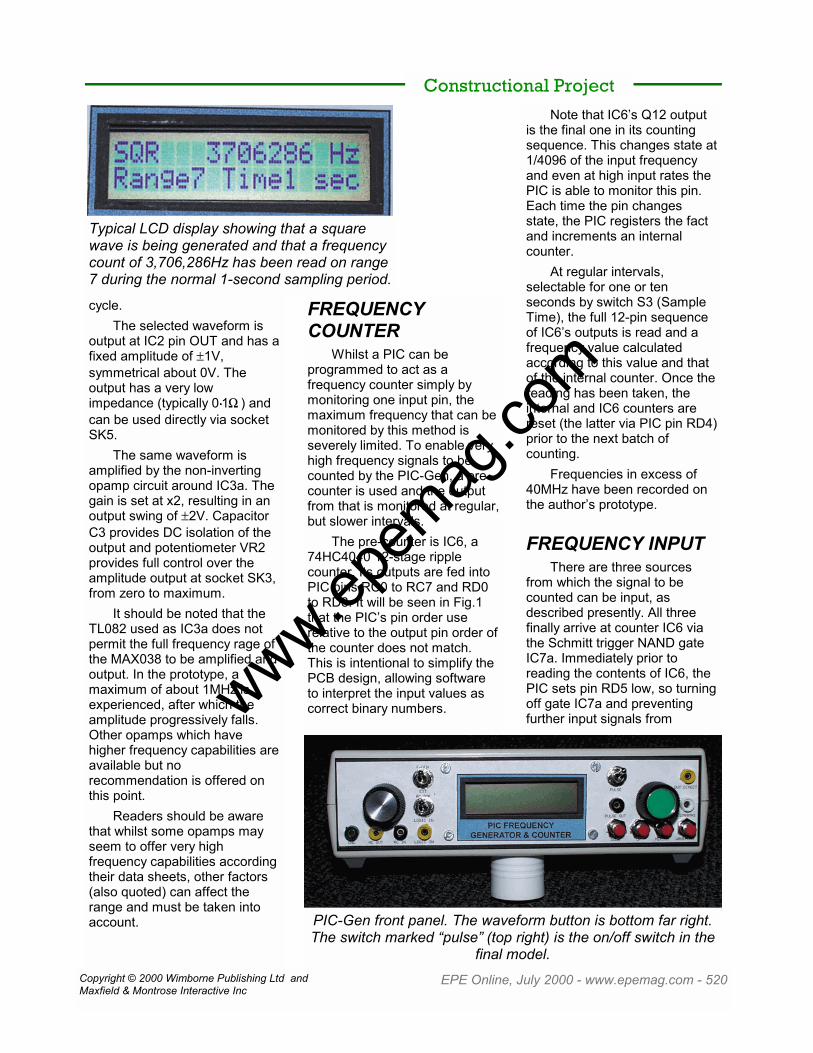
Typical LCD display showing that a squarewave is being generated and that a frequencycount of 3,706,286Hz has been read on range7 during the normal 1-second sampling period.
PIC-Gen front panel. The waveform button is bottom far right.The switch marked “pulse” (top right) is the on/off switch in the
final model.
www.epem
ag.co
m
Copyright © 2000 Wimborne Publishing Ltd andMaxfield & Montrose Interactive Inc
EPE Online, July 2000 - www.epemag.com - 521
reaching the counter. Thisallows the ripple-nature of thecounter to stabilize (ripplethrough) at the correct countvalue. Software introduces aslight delay between closing thegate and taking the reading.
Constructional ProjectLogic level signals
(nominally 0V to 5V) are input tothe PIC-Gen via socket SK1(Logic Input), switch S5selecting their routing to gateIC7a and the counter. Signalshaving other voltage ranges,
either above or below the 0V/5Vrange should not be input tosocket SK1. Those havinglesser swings may not triggergate IC7a, those having swingsgreater than about 6V could killit.
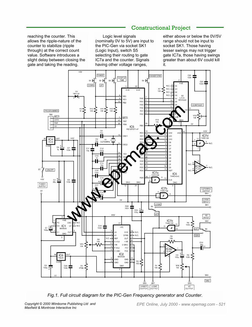
Fig.1. Full circuit diagram for the PIC-Gen Frequency generator and Counter.
www.epem
ag.co
m

Copyright © 2000 Wimborne Publishing Ltd andMaxfield & Montrose Interactive Inc
EPE Online, July 2000 - www.epemag.com - 522
Signals which are analog ordigital and have a swing rangeless than 5V, but greater thanabout 2V to 2����5V, are input viasocket SK2 (AC Input). SwitchS6 selects their routing to thepre-conditioning circuit aroundIC7c. This is another Schmitttrigger NAND gate, having oneinput (pin 13) held biassed at amid-power line level (2����5V) bythe potential divider formed byresistors R8 and R9. The otherinput (pin 12) is held at +5V.
The input signal is ACcoupled via C10 to the biasedinput of the gate. Providing theinput signal’s peak-to-peakrange is greater than the gate’shysteresis value (which variesslightly between individualdevices), so the gate will betriggered.
The output of this gate isalso fed to switch S5, whichroutes it to the counter via IC7awhen selected.
Because the main outputsignal from the MAX038 has apeak-to-peak swing of �1V, ittoo has to be pre-conditioned viaIC7c before its frequency can becounted, the routing also beingselected by switches S6 and S5,respectively.
LOGIC OUTPUTThe output from IC7c is
additionally fed to socket SK7allowing, for example, thefrequency generated by theMAX038 to be used as a 5Vsquare wave (irrespective ofwhich waveform is beinggenerated), or for the a.c. signalto be converted to 5V pulses(whose width depends on thenature of the signal).
Whilst the MAX038 has itsown 5V square wave availableat the SYNC pin (when pin +DVis held high), it was found that
instability occurred when thiswas generated (as cautioned inMaxim’s data sheet).Consequently, the option to usethis output has been droppedfrom the published PIC-Gen(although the connection trackson the PCB have beenretained).
3·2768MHz OUTPUTThe PIC is run at a
frequency of 3����2768MHz, as setby crystal X1. Although thisfrequency can be tapped directlyfrom PIC pin OSC2, it wasdeemed better to buffer it viagate IC7b before releasing it tothe outside world through socketSK4. The output is a 5V squarewave.
DISPLAY MODULEAs is common with so many
recent EPE Online PIC projects,an alphanumeric liquid crystaldisplay (LCD) is used. Thisshows the frequency count andsampling rate, plus thegenerated waveform selectedand its frequency range (as anumber between 0 and 7, where0 is the lower frequency range).The information displayed takesa form similar to:
SINE 25124HzRange4 Time1 sec
where:
o) Line 1 left: waveform
selected (sine, triangle orsquare).
o) Line 1 mid/right:frequency value.
o) Line 2 left: frequencyrange selected (8choices).
o) Line 2 mid/right:sampling range selected(2 choices).
The LCD is shown as X2 inFig.1. It is under standard 4-bitcontrol, but whereas many PICprojects control it via PIC Port B,here it is controlled via Port A(RA0 to RA5). Apart from thechange of PIC port registernumber, the software routinethat drives the LCD is theauthor’s usual “library” routine.
It is worth noting, though,that because Port A RA4 is anopen-collector pin, resistor R7has to be used to bias it high inorder to correctly control LCDpin D5.
The LCD screen contrast isadjustable by preset VR3.
POWER SUPPLYIt is intended that the PIC-
Gen should be powered at 9V,either from a 9V battery or a 9Vmains power supply (in fact,input supply voltages betweenabout 7V and 12V areacceptable). Regulator IC5drops and stabilizes the inputsupply at 5V. This powers IC3,IC5 to IC7, and the LCD. Thesedevices must not be powered
Constructional Project
This display shows a sine wave is being generated and afrequency of 25,124Hz has been registered via range 4.
www.epem
ag.co
m

Copyright © 2000 Wimborne Publishing Ltd andMaxfield & Montrose Interactive Inc
EPE Online, July 2000 - www.epemag.com - 523
within the PIC-Gen circuit at anyother voltages (normal powersupply tolerances apply).
The 5V supply is also usedby the MAX038, but this deviceadditionally requires a supply of–5V. A double-staged circuit isused for this purpose, based
around IC1 and IC8.IC1 is a MAX660 voltage
converter, used here togenerate a negative voltage ofthe same (inverse) magnitudeas the voltage at which it ispowered. In this instance, the 9V
supply is inverted to become –9V.
The MAX660 has a muchgreater output load capabilitythan the more familiar ICL7660(and similar) devices, typicallyabout 100mA as compared with20mA. ONLY the MAX660should be used in the PIC-Gen.
It had been expected thatthe MAX660 could have beenpowered by the 5V regulatedsupply from IC4, producing –5Vas a result. However, the firsttest model of the PIC-Genshowed significant instability inthe frequency generated whenthis method was used.Investigation showed that theripple frequency output by theMAX660 could not bedampened sufficiently to preventit from modulating the MAX038frequency output.
Constructional Project
S1 to S4 s.p. push-to-make switch (4 off)S5 to S7 s.p.d.t. miniature toggle switch (3 off)X1 3.2768MHz crystalX2 2-line 16-character (per line) LCD module (see text)
PCB available from the EPE Online Store (code 7000268) at www.epemag.com.knob (2 off); 8-pin DIL socket (2 off); 14-pin DIL socket; 16-pin DIL socket; 20-pinDIL socket; 40-pin DIL socket; 1mm pin header strips (see text); 1mm terminalpins;2mm socket (7 off, various colors) (or sockets to suit other equipment); plasticcase,205mm x 108mm x 57mm; plastic feet for case (4 off); PCB mounting supports(4 off); PP3 battery and clip, or socket to suit external power supply (see text);connecting wire; cable ties; solder, etc.
COMPONENTSResistors
R1 470 ohmsR2, R4, R5, R7, R10 to R13 10k (8 off)R3 10 ohmsR6 1kR8, R9 100k (2 off)
CapacitorsC1 to C3, C18 to C24 100u radial electrolytic, 16V (5 off)C4, C10 22u radial electrolytic, 10V (2off)C5, C7, C15, C19 to C23 100n ceramic disk, 5mm pitch (8 off)C6, C16 1u radial electrolytic, 10V (2 off)C8, C9, C11 10p ceramic disk, 5mm pitch (3 off)C12 100p ceramic disk, 5mm pitchC13 1n ceramic disk, 5mm pitchC14 10n ceramic disk, 5mm pitchC17 10u radial electrolytic, 10V
Miscellaneous
See also theSHOP TALK Page!
$90Approx. CostGuidance Only (Excluding case, batts)
PotentiometersVR1 10k panel mounting rotary or multi-turn linear (see text)VR2 10k panel mounting rotary lin.VR3 10k miniature preset, round
SemiconductorsD1 1N4148 signal diodeIC1 MAX660 DC-to-DC converterIC2 MAX038 function generatorIC3 TL082 dual opampIC4 78L05 +5V voltage regulatorIC5 PIC16F877-4P microcontroller (pre-programmed -- see text)IC6 74HC4040 12-stage binary ripple counterIC7 74HC132 quad dual-input Schmitt NAND gateIC8 79L05 -5V voltage regulator
Completed prototype PCB. Differsslightly from final model.
www.epem
ag.co
m
Copyright © 2000 Wimborne Publishing Ltd andMaxfield & Montrose Interactive Inc
EPE Online, July 2000 - www.epemag.com - 524
Consequently, it was foundnecessary to first generate –9Vand then to regulate andstabilize it down to –5V usingIC8, a negative voltageregulator. Further smoothing isgiven by the use of resistor R3and capacitors C23 and C24.
A small instability remains,believed to be due to theMAX066’s square waveoscillator radiating into otherparts of the circuit (anoscilloscope probe on a range of10mV just picks up the signalwhen held near to the device).The instability is principallynoticeable at higher MAX038frequencies.
PROGRAMMINGCONNECTIONS
As is customary with theauthor’s recent PIC projects, thePIC device used in this circuitcan be programmed in-situ onthe printed circuit board. Theusual four connections areprovided, ~MCLR (Vpp), DATA,CLK, and 0V, accessible viaconnector TB2, whoseconnections are in the samenow-familiar order. Diode D1and resistor R6 are part of therequired control configuration.The EPE PIC Toolkit Mk2 (May/June ’99) is an idealprogrammer to use.
MISCELLANYResistors R10 to R13 are
pull-down resistors toappropriately bias the respectivePIC input pins when switches S1to S4 are not pressed. NANDgate IC7d has its inputs biassedto a power line (+5V in thiscase) as is required for unusedCMOS gates. Opamp IC3b hadbeen intended for use as anexternal analog input amplifier,but it was decided that theconfiguration around IC7c
provided cleaner signal control,and at a far higher frequency.
If users need to frequency-
count signals having a peak-to-peak value less than about 2V,they should pre-amplify themfirst.
Constructional Project
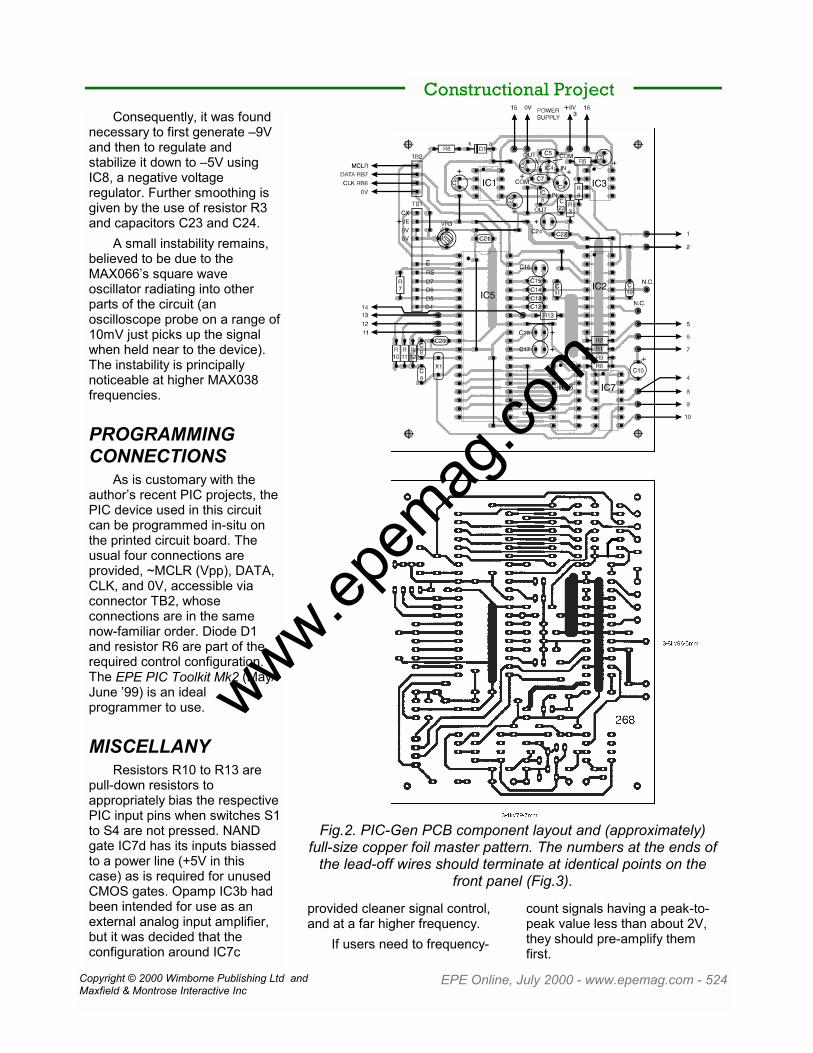
Fig.2. PIC-Gen PCB component layout and (approximately)full-size copper foil master pattern. The numbers at the ends of
the lead-off wires should terminate at identical points on thefront panel (Fig.3).
www.epem
ag.co
m

Copyright © 2000 Wimborne Publishing Ltd andMaxfield & Montrose Interactive Inc
EPE Online, July 2000 - www.epemag.com - 525
Only the HC versions of IC6and IC7 should be used(74HC4040 and 74HC132).These are typically capable ofhandling signals in excess of40MHz. The “standard” CMOS4040 counter is far too slow tobe usable in this circuit. The use
of a 74LS132 should allowlesser amplitude externalsignals to be input to thefrequency counter, typicallyhaving a peak-to-peak swing ofabout 0����8V, although this has notbeen tried.
Numerous smoothing
capacitors are used throughoutthe circuit at strategic points onthe PCB.
CONSTRUCTIONDetails of the component
and track layouts for the PIC-
Constructional Project
Fig.3. Layout and wiring to the front panel (full size) mounted components. The inset panelsshow wiring to a multiturn pot and suggested wire groupings.
Layout of components and wiring inside the case of the completed prototype PIC-Gen.There are very minor differences between this and the final wiring diagrams.
Note the various wiring “looms”.
www.epem
ag.co
m

Copyright © 2000 Wimborne Publishing Ltd andMaxfield & Montrose Interactive Inc
EPE Online, July 2000 - www.epemag.com - 526
Gen PCB are shown in Fig.2.This board is available from theEPE Online Store (code7000268) at www.epemag.com
The author’s preferredassembly is in order of link wires(some go under IC positions), ICsockets, resistors, diode, smallcapacitors, and remainingcomponents in ascending orderof size. Do not insert the DIL(dual-in-line) ICs at this stage.
Ensure that all polarizedcomponents are orientated asshown in Fig.2.
Pin-header strips were usedfor terminal groups TB1 andTB2. The order of theseconnections is identical to thatused in the author’s recent PICprojects. Details of the sourcefor the LCD module completewith matching connector aregiven on this month’s Shoptalkpage.
The prototype PIC-Gen ishoused in a plastic casemeasuring 205mm x 108mm x57mm. The layout andinterwiring of the off-boardcomponents on the rear of thecase’s front panel are shown inFig.3. The illustration is to scale.(Note that the photographs showslightly different panel wiring tothat in Fig.3.)
A choice of frequencycontrol potentiometer is offered.The illustration in Fig.3 showsthe connections for VR1 as astandard single-turn carbonrotary potentiometer. The insetshows the typical connectionsfor a multiturn (10-turn in theprototype) wirewoundpotentiometer.
The standard pot is the leastexpensive choice but does notallow the same degree offrequency setting precision asthe more-expensive multiturnpot.
To minimize the possibility
of signals interacting with eachother through the interwiring,several “harness” groups wereused, keeping potentiallyinteractive signal paths apart asseemed reasonable. The groupscan be seen in the photograph,and they are itemized byconnection number in thesecond insert of Fig.3.
Several cable ties are usedto keep each group separatelyharnessed.
CHECK-OUTDuring the checking-out of
the circuit, power should alwaysbe switched off before insertingICs or making other alterations.Switch off immediately if thecircuit does not behave asexpected, rechecking yourassembly for errors.
Assuming that you havethoroughly checked that youhave not made assembly orsoldering errors, the first checkshould be with the LCD and allICs omitted except the tworegulators IC4 and IC8.
With power applied, checkthat +5V is present at the outputof IC4 and at strategic pointsaround the PCB (referring toboth Fig.1 and Fig.2).
Insert the negative voltage
converter IC1 and check that anegative voltage equivalent tothe applied power supply ispresent at it’s output (i.e. –9V fora +9V supply). Check that –5Vis present at the output ofregulator IC8 and at the pin 20position of the socket for IC2.
If all is satisfactory, theremaining ICs and the LCD canbe inserted. Only one LCD linewill be active until the PIC isrunning. Adjust preset VR3 untilthe active pixels are seen asslightly darkened rectangles, orthe displayed text is clearlyvisible if the PIC is running.
If not already programmed,the PIC can have its programdownloaded to it on the PIC-Genboard from a suitable PICprogrammer, connecting theprogrammer via pin header TB2.
The PIC configuration(initialization) required is the PICToolkit Mk2 default as shown inTable 1.
Once programmed, the PICshould immediately start runningand a set of data similar to thatpreviously discussed should beseen. Set switches S5 and S6so that the frequency beinggenerated by IC2 is beingmonitored. Observe the resultswhen different waveforms,frequency ranges and samplingrates are selected using
Constructional Project
When the sampling rate change switch is pressed,the word “counting” is displayed until the first newcount has been completed. In this instance a 10-
second sampling rate has been selected.
CP11
CP01
DBG1
NIL1
WRT1
CPD1
LVP0
BOR0
CP11
CP01
POR0
WDT0
OS10
OS01
Table 1: PIC16F877 configuration bits.
www.epem
ag.co
m

Copyright © 2000 Wimborne Publishing Ltd andMaxfield & Montrose Interactive Inc
EPE Online, July 2000 - www.epemag.com - 527
switches S1 to S4 and with thefrequency control potentiometerVR1 at various settings.
If you have an oscilloscope,monitor the waveforms output atall settings and from all paneloutputs. Additionally check thetwo inputs, using an externalsignal generator. Outputs OutDirect and AC Out should onlybe fed into the AC Input (do notfeed them into the Logic Inputbecause of their negative-goingcontent).
(You may prefer to insert a1k resistor between socket SK1
Constructional Projectand switch S5 to minimize therisk of IC7a becomingdistressed by negative-going orover-voltage signals.)
Once fully checked, the PIC-Gen is ready to be put intogeneral workshop use.
RESOURCESThe software for the PIC-
Gen is available for freedownloaded from the EPEObline library atwww.epemag.com. Theprogram is written in TASM.
Data sheets for the MAX038and MAX660 can bedownloaded from Maxim’s website at www.maxim-ic.com
Data sheets for thePIC16F877 (and other PICproducts) can be downloadedfrom Microchip’s web site atwww.microchip.com
www.epem
ag.co
m