- Overview about Malaysia oil and gas - level of realism to traditional drawing (2D dwg) - Be able...
19
- Overview about Malaysia oil and gas - level of realism to traditional drawing (2D dwg) - Be able to store huge amount of data referring. - Single source of engineering data with multi database. - 3D contributes to the quality of design are: a) Ensures consistent and reliable component data. From old methods to Autocad and 3D software. b) Adheres to definable engineering specifications. All input from standard component ANSI/ASME in pdms. c) Ensures correct geometry and connectivity. Checking data inconsistency check d) Avoids component interferences. Visual checks and Clash report e) Annotation and dimensions obtained directly from the design database. PLANT DESIGN MANAGEMENT SYSTEM
-
Upload
percival-wilcox -
Category
Documents
-
view
214 -
download
0
Transcript of - Overview about Malaysia oil and gas - level of realism to traditional drawing (2D dwg) - Be able...

- Overview about Malaysia oil and gas - level of realism to traditional drawing (2D dwg)- Be able to store huge amount of data referring.- Single source of engineering data with multi database.- 3D contributes to the quality of design are: a) Ensures consistent and reliable component data. From old methods to Autocad and 3D software. b) Adheres to definable engineering specifications. All input from standard component ANSI/ASME in pdms. c) Ensures correct geometry and connectivity. Checking data inconsistency check d) Avoids component interferences. Visual checks and Clash report e) Annotation and dimensions obtained directly from the design database.
PLANT DESIGN MANAGEMENT SYSTEM

3D STORAGE

Database
3D modeling database are:-- Admin database. User, Team, Database, Multi-Database and etc- Catalogue and Specifications database. Category, Point Set, Geometry Set and reference- Design database. Equipment, Pipework, Cable Tray, Hvac and Structural Produced material take off from design - Draft database. Produced Piping general arrangement- Isodraft database. Produced isometric drawing- Spooler Database- Produced fabrication isometric drawing

Design Modules
- 3D design with full sized three dimensional plant model.- Component selection is provided through specification dictate from catalogue.- Design modules can check interferences between items.- Flexible reporting capability to produce Material Take-Off.- Previewed isometric drawing.- Produced Equipment layout and Piping General arrangement- Spooler allow designer to split the pipe work for fabricator.
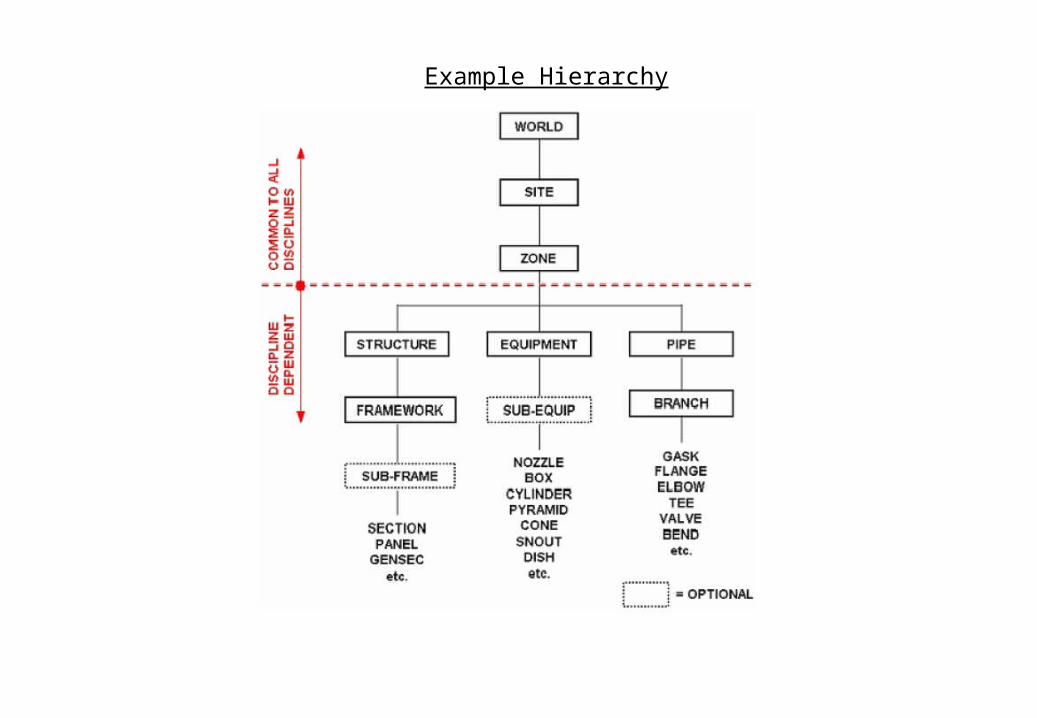
Example Hierarchy
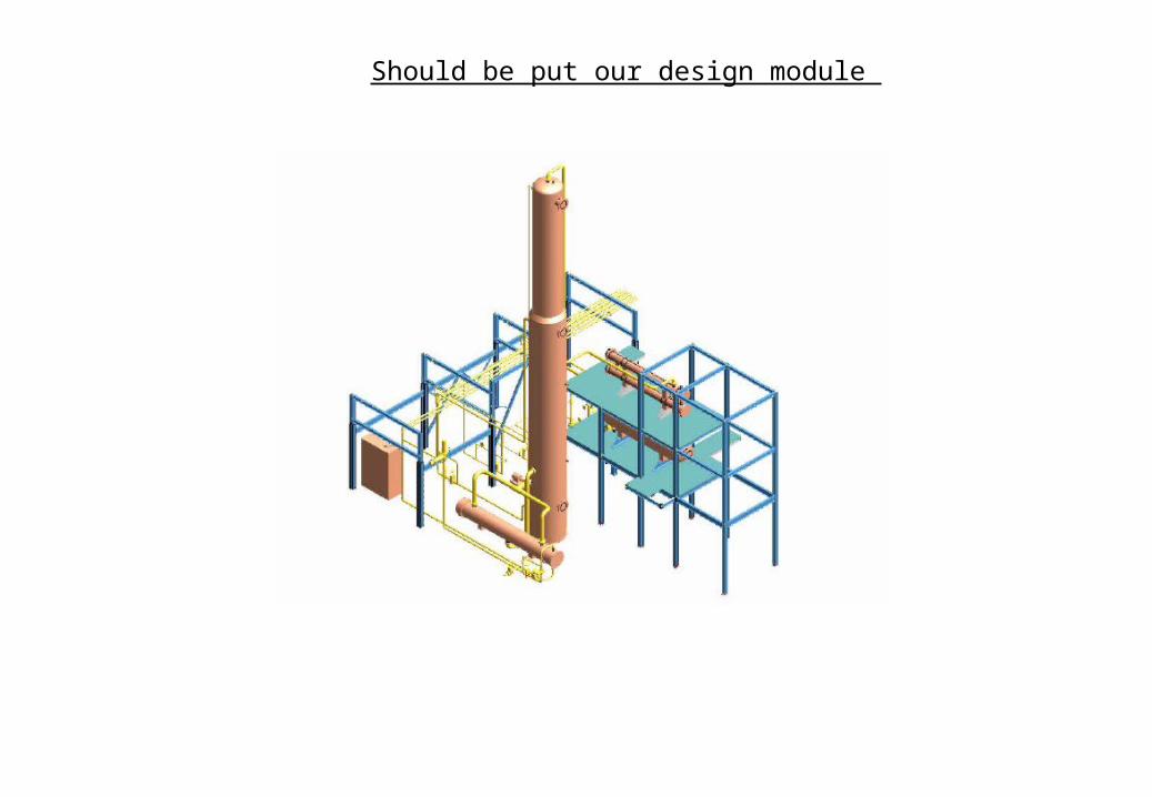
Should be put our design module

Drafting Modules
General Arrangement
-To be able dimension and annotated with scale from design database.- Annotation can be in the form of labeling.- Automatically dimension and recalculated update if 3D position moved in design.
Isodraft
- Automatically annotated and dimensioned piping isometric drawing.- Isometric can suit pipe fabricators and erectors.- Full material lists.- Automatic spool identification.- Automatic splitting of complex drawings based on design module.- User defined drawing sheets.

Example General Arrangement

Example Isometric Drawing
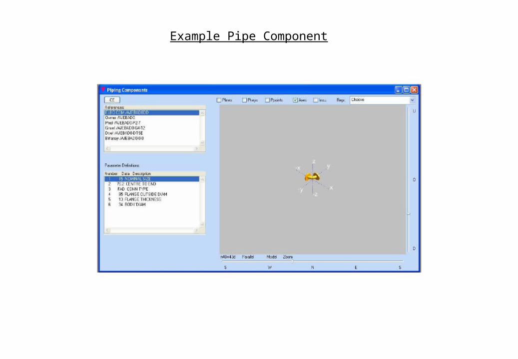
Example Pipe Component

Example Design Components

Example Pipe Design

Example Structural Design

Pressure Vessel
Notes
- Horizontal vessel should be along the natural ventilation path to reduce the potential for an explosion overpressure- Manholes and access platforms should preferably be located on the access aisles- All instruments standpipes, sampling points should be located at one side of a horizontal vessel to facilitate operation and maintenance.- A davit usually handles piping component and vessel internals- When arranging common platforms for vessels in-line, allowance shall be provided for differential expansion between vessels.

Pumps
Notes
- Pump suction and discharge should face and be located close to the equipment - When locating the pumps, ensure that NPSH requirements are met.- Pump handling flammable products shall not be located under vessel.- High pressure charge pump should be separated from any other major process equipment and other pumps.- Maintenance access is the space required to service in-place or to remove the unit in components for offsite repair.- Instruments shall not subjected to excessive vibration ( e.g. on suction or discharge lines of pumps 0 or to mechanical stresses and are not to exposed to temperature that will influence the measurement.- -

- Accessibility identifies the effort required for a healthy human being to reach devices such as an instrument ,measuring element , instrument process connection, instrument utility connection, block valve or sampling point for the purpose of operational attention of regular maintenance. It includes the ability to reach such a device with all tools required to perform operational attention or maintenance. Accessibility level are defined as follows:
Accessibility
1. Permanent accessibility .2. Limited Accessibility3. Poor Accessibility4. Inaccessibility

- On-line instruments are to mounted on or in direct vicinity of the instrument process connections-The location shall guarantee a good representative measurement of the process condition- Limited accessibility is acceptable for indicating instruments, provided that they could be properly read from a permanently accessible location.- Instruments and their impulse lines shall be surrounded by sufficient free space to allow rodding-out of process connections and the removal of :: Bolts , nuts and gaskets ,etc: Covers and enclosures.: Orifice plates from the orifice plates.: Removable parts from in-line flow meters.: Internals from the control valve.:Thermometer elements from the thermowells- Permanent and easy access for maintenance purpose used to be the dominant factor in selecting the physical location of plant mounted instruments. This resulted in long impulse lines and additional ladders/platforms.
Accessibility

- Access arrangement for all regular operations should be straightforward and simple.- Permanently installed auxiliary platforms and ladders should be considered.- Provisions should be provided for all routine operations that will involve handling and storage of materials.- Instruments and operational checkpoints should be positioned so as to allow access from deck levels or permanents platforms or ladders.- Instruments and operational checkpoints should be positioned so as to allow access from skid levels or permanents platforms or ladders.- Equipment parts, instruments, valve handwheels, and piping shall not protrude into the access ways.-
Provisions for Routine Operations

- To know about the pipe component fitting valve - To know about pipe connection, flange connection, and etc - To know look like the pipe presentation in the drawing - To know look like pipe in isometric in isometric- - To know what is the structural .- To know instruments connection in piping.- To know
Basic Design