> - OILWEB standard_old/Std-179.pdf · mother compressor station. 3.13 CNG daughter station: CNG...
16
Transcript of > - OILWEB standard_old/Std-179.pdf · mother compressor station. 3.13 CNG daughter station: CNG...

<< Back Home Next >>

2
NOTE OISD publications are prepared for use in the oil and gas industry under Ministry of Petroleum & Natural Gas. These are the property of Ministry of Petroleum & Natural Gas and shall not be reproduced or copied and loaned or exhibited to others without written consent from OISD. Though every effort has been made to assure the accuracy and reliability of the data contained in these documents, OISD hereby disclaims any liability or responsibility for loss or damage resulting from their use. These documents are intended to supplement rather than replace the prevailing statutory requirements.

3
FOREWORD The Oil Industry in India is more than 100 years old. As such, a variety of practices have been in vogue because of collaboration/ association with different foreign companies and governments. Standardisation in design philosophies , operating and maintenance practices was hardly in existence at a national level. This, coupled with feed back from some serious accidents that occurred in the recent past in India and abroad, emphasised the need for the industry to review the existing state of art in designing, operating and maintaining oil and gas installations. With this in view, the Ministry of Petroleum & Natural Gas in 1986 constituted a Safety Council assisted by the Oil Industry Safety Directorate (OISD) staffed from within the industry for formulating and implementing a series of self regulatory measures aimed at removing obsolescence, standardising and upgrading the existing standards to ensure safer operations. Accordingly, OISD constituted a number of functional committees comprising of experts nominated from the industry to draw up standards and guidelines on various subjects. The present document “Safety Requirements on Compression, Storage, Handling & Refuelling of Natural Gas for Use in Automotive Sector” was prepared by the Functional Committee on “Safety Requirements on Compression, Storage, Handling & Refuelling of Natural Gas for Use in Automotive Sector”. This document was prepared based on the accumulated experience and knowledge of industry members, and various national and international codes and practices. This document will be reviewed periodically for improvements based on the new experiences and better understanding. Suggestions from industry may be addressed to : The Coordinator, Committee on “Safety Requirements on Compression, Storage, Handing & Refuelling of Natural Gas for Use In Automotive Sector”
OIL INDUSTRY SAFETY DIRECTORATE 7TH FLOOR, NEW DELHI HOUSE 27, BARAKHAMBA ROAD NEW DELHI - 110 001.
4
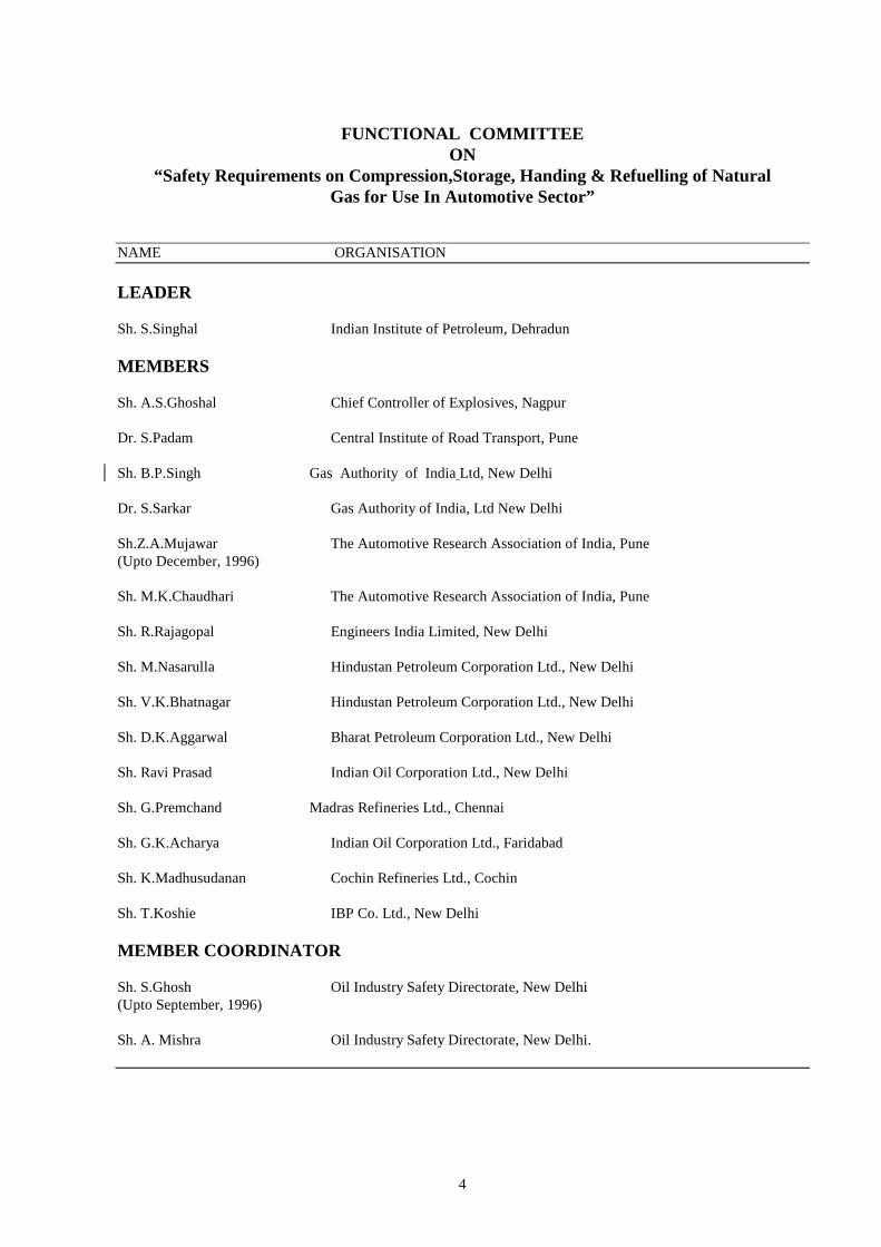
FUNCTIONAL COMMITTEE
ON “Safety Requirements on Compression,Storage, Handing & Refuelling of Natural
Gas for Use In Automotive Sector”
NAME ORGANISATION LEADER Sh. S.Singhal Indian Institute of Petroleum, Dehradun MEMBERS Sh. A.S.Ghoshal Chief Controller of Explosives, Nagpur Dr. S.Padam Central Institute of Road Transport, Pune Sh. B.P.Singh Gas Authority of India Ltd, New Delhi Dr. S.Sarkar Gas Authority of India, Ltd New Delhi Sh.Z.A.Mujawar The Automotive Research Association of India, Pune (Upto December, 1996) Sh. M.K.Chaudhari The Automotive Research Association of India, Pune Sh. R.Rajagopal Engineers India Limited, New Delhi Sh. M.Nasarulla Hindustan Petroleum Corporation Ltd., New Delhi Sh. V.K.Bhatnagar Hindustan Petroleum Corporation Ltd., New Delhi Sh. D.K.Aggarwal Bharat Petroleum Corporation Ltd., New Delhi Sh. Ravi Prasad Indian Oil Corporation Ltd., New Delhi Sh. G.Premchand Madras Refineries Ltd., Chennai Sh. G.K.Acharya Indian Oil Corporation Ltd., Faridabad Sh. K.Madhusudanan Cochin Refineries Ltd., Cochin Sh. T.Koshie IBP Co. Ltd., New Delhi MEMBER COORDINATOR Sh. S.Ghosh Oil Industry Safety Directorate, New Delhi (Upto September, 1996) Sh. A. Mishra Oil Industry Safety Directorate, New Delhi.

5
1.0 INTRODUCTION
Compressed Natural Gas (CNG) has been identified as one of the alternate fuels to liquid petroleum fuels, which has added environmental benefits. This fuel is being used internationally with the proven success as an automotive fuel.
CNG is a mixture of hydrocarbon gases and vapours consisting of principally methane in gaseous form which are compressed to a pressure of 200 to 250 Kg/ Sq.cm.g. for use as a vehicular fuel. Besides, installation of conversion kit in an Automotive system, two major installations need to be erected i.e.
1) Compressors station for either on-line operation or to serve as mother station
2) Refuelling station either with on-line facility or with moveable cascade.
These facilities may be either co-located in the MS/HSD dispensing stations or at dedicated stations.
Safety at these installations is most important factor in view of the operating conditions such as pressure, storage of other flammable materials etc. The provisions in this standard shall provide a reasonable level of safety and protection from loss of life and property from fire and explosion.
2.0 SCOPE
This standard lays down the minimum safety requirements at installations (as described in 1 above) handling Natural Gas for dispensing into vehicles and minimum checks required in the vehicles by Refuelling stations. This standard does not certify the fitness of vehicles either for CNG use or otherwise. Further, this standard only supplements the existing statutory regulations and in no way supercedes them. The statutory regulations must be followed as applicable.
It is not intended that requirements of this standard should be applied rigidly to existing installations duly approved by Chief Controller of Explosives, where for a variety of reasons it may not be practicable to comply with. This standard will however, create awareness and help in selective
implementation at existing installations as far as possible.
3.0 DEFINITIONS 3.1 ANSI B 31.3.
This code of American National Standards Institute on "Chemical Plant and Petroleum Refinery Piping" would be applicable for CNG Pipelines and tube work inside the installation of CNG compression and retail outlets.
3.2 Statutory Authority.
Govt. of India or its agency responsible for particular aspect. “Chief Controller of Explosives” is the statutory Authority for administering the Gas Cylinder Rules 1981 & SMPV Rules 1981.
3.3 Bulk Storage.
Bulk storage is a facility for storing CNG in stationary and mobile storages exceeding the capacity of 1000 Lt. These pressure vessels shall conform to the “Static & Mobile Pressure Vessels (Unfired) Rules, 1981 as amended.
3.4 Capacity.
The gross capacity of a storage container in water litres at 15 deg. C.
3.5 Cascade (Gas Storage Unit)
This is a group of gas cylinders with a total water capacity not exceeding 4500 Litres, contained within a length of 5.5M, a height of 1.6M and a width of 1.2M in case of cylinders kept vertical, or 5.5M, 1.6M and width of 1 cylinder upto 2M in case of horizontal cylinders. Either arrangement used shall be interconnected by high-pressure piping to form a single gas storage unit referred as cascade hereafter. (‘M’ denotes meters).
The cascade is also used for transportation of CNG in the structural container having facility for lifting and placement.
3.6 Cascade Storage Unit Isolation Valve.

2
This is a quick action valve for stopping gas flow from a gas storage unit.
3.7 Compressed Natural Gas (CNG).
Mixtures of hydrocarbon gases and vapours, consisting mainly of Methane in gaseous form which has been compressed for use as automotive fuel.
3.8 Cylinder Appurtenances.
Devices connected to cylinder for safety, control or operating purposes.
3.9 Cylinder.
A pressure vessel having capacity exceeding 500 ml but not exceeding 1000 lts., constructed as per IS: 7285 or other international standards having approval from statutory authority under Gas Cylinder Rules. These may be of varied capacities to suit vehicles and storage systems.
3.10 Dew point.
The temperature at which the water vapours begins to condense.
3.11 CNG “Mother” Station :
CNG facility connected to natural gas pipeline and having a compressor meant primarily to fill mobile cascades for ‘daughter’ stations. Such facilities, in addition to act as ‘mother’ station can also fill stationary cascades for CNG dispensing into vehicles.
3.12 CNG “On line” Station:
CNG facility connected with natural gas pipeline and having a compressor primarily to fill stationary cascades for dispensing CNG to vehicles. In case the ‘on line’ station has enough space to accommodate mobile cascades filling, it can be used to act as mother compressor station.
3.13 CNG daughter station:
CNG facility not connected to natural gas pipeline and dispensing CNG to the vehicles (s) through mobile cascades.
3.14 Emergency Shut Off Valve.
A quick action shut off valve, which operates from full open to full closed condition in less than one complete turn.
3.15 Fire Resistance Rating (FRR).
The minimum period of time for which all sides of an element of structure, any of which is subjected to a standard fire, continues to perform its structural function and does not permit the spread of fire. Where a period of time is used in conjunction with the abbreviation FRR it is required that the element of structure referred to shall have a fire resistance rating of not less than the period stated.
3.16 Hazardous.
Substance or circumstance which may cause injury or damage due to being explosive, flammable, poisonous, corrosive, oxidizing, or otherwise harmful.
3.17 Installation.
System that includes natural gas containers, pressure booster, compressors, dispensers and all attached valves, piping, and appurtenances. When filling containers or transferring natural gas directly from distribution lines by means of a compressor, an installation includes the compressor and all piping and piping components beyond the shut off valve between the distribution system and the compressor.
3.18 Manifold.
The assembly of piping and fittings used for interconnecting all cylinders/ vessels to a common pipeline.
3.19 Non Return Valve (NRV).
This valve permits gas flow in one direction only.
3.20 Natural Gas.
Mixture of gaseous hydrocarbons and vapours consisting primarily of Methane.
3.21 Noncombustible Material.

3
Material, in the form in which it is used and under the conditions anticipated, will not ignite, burn, support combustion, or release flammable vapours when subjected to fire or heat.
3.22 Point of Transfer.
The point where the fuelling connection is made, to vessel(s)/ vehicle (s).
3.23 Pressure Relief Device.
Device designed to prevent rupture of vessel / container by releasing excessive pressure build-up as specified in clause 18 of SMPV Rules, 1981. The systems and components of CNG facilities are required to be certified for CNG use and marked accordingly.
3.24 Set Pressure.
The valve opening pressure in a relief valve which shall not exceed the marked service pressure.
3.25 Shall.
Indicates mandatory requirement. 3.26 Should.
Indicates recommendation or that which is advised but not mandatory.
3.27 SMPV Rules.
The Static and Mobile Pressure Vessels (Unfired) Rules, 1981, (with latest amendments) abbreviated as SMPV. These are Rules governing the storage, transportation, handling etc. of compressed gas in vessels exceeding 1000 litres in volume. These rules are framed under the Indian Explosives Act, 1884 and administered by Chief Controller of Explosives.
3.28 Gas Cylinder Rules, 1981:
Rules governing the fabrication, storage, transportation, handling etc. of cylinders. These rules are framed under the Indian Explosives Act, 1884 and administered by Chief Controller of Explosives.
3.29 Sources of Ignition.
Devices or equipment which, because of their mode, use or operation, are capable of providing required thermal energy to ignite flammable "CNG-Air mixtures" when introduced to such a mixture or when such a mixture comes into contact with them.
3.30 Transport Vessel.
A cascade/ bulk storage mounted and installed on a Light/ Heavy Commercial Vehicle, trailer, or semi trailer for movement of CNG on road and governed by statutory regulations.
3.31 Working Pressure.
The pressure for which the equipment was constructed or if conditions have changed, the maximum pressure at specified temperatures, permitted at the most recent inspection.
3.32 Vehicle Refuelling Probe.
This is a CNG refuelling device fitted at the end of the refuelling hose at the dispenser units suitable for insertion into the vehicle refuelling valve receptacle.
3.32 Vehicle Refuelling Shut Off Valve.
A quick action valve for stopping gas flow and having the facility for venting residual high pressure gas in the refuelling line after completion of the vehicle refuelling operation.
4.0 APPROVAL 4.1 The systems and components of CNG
facility(s) are required to be certified for CNG use and marked accordingly by applicable statutory authority or his agent. The various components of the CNG system which need such certification/ approval are given below:
a) Cylinders b) Pressure relief devices
including pressure relief valves c) Pressure gauges d) Pressure regulators e) All parts under pressure carrying
CNG/NG including valves.

4
f) Hose and hose connections g) Vehicle fuelling connections h) Electrical equipment related
to CNG systems 4.2 Any other device not specified above must be
constructed to provide safety equivalent to that required for other parts of a system and should have a similar certification/ approval as detailed above.
5. 0 NATURAL GAS QUALITY FOR
CNG FACILITIES 5.1 The principal constituent of CNG is methane
alongwith some amounts of other elements. Out of these, concentration of undesirable constituents shall be restricted to the following:
a) Carbon dioxide, partial pressure 7 psi max
b) Oxygen 0.5 vol. % max c) Hydrogen Sulphide
and soluble sulphides partial pressure .05 psi max
d) Moisture contain 7.0 lb. /MMCF. Max
NB: when the dew point of the gas entering the cylinder is below the lowest anticipated container temperature at the maximum anticipated container pressure, the above shall not apply.
5.2 ODOURISATION: 5.2.1 Natural gas introduced into any system
covered by this standard should have a distinctive odour strong enough to detect its presence down to a concentration (of CNG) in air not exceeding 20% of the lower limit of flammability. To achieve this, the injection of odorizing agent shall be done in a quantity to ensure perception of CNG leakage by smell.
5.2.2 Suitable type of filters shall be used for
limiting liquid particulate as mentioned in the clause 5.2.1.
5.2.3 The odorisation and filtration system shall be
located in a separate working area from the compressor or CNG storage unit but within the same fencing. There should be a clear
safety distance of 1.5 M around the odorisation and filtration system to facilitate easy maintenance and personnel movement.
5.2.4 The odorisation pumping as well as filtration
system shall have 100% stand-by capacity. 6.0 FACILITY PLANNING 6.1 The CNG Refuelling system shall comprise
of a gas compression apparatus, static/ mobile cascade/ pressure vessel and a gas dispenser incorporating a measuring device. The system shall be `ON-LINE' mother refuelling or daughter dispensing system attached to a mobile cascade.
6.2 LAYOUT AND INTERDISTANCES 6.2.1 Inter-distances between various equipment,
storage cylinders/ cascade etc. shall be as per Table - I, II.
6.2.2 Safety distances not indicated above should
be as approved by Chief Controller of Explosives on case to case basis after due consideration of all influencing factors.
6.2.3 When inside a MS-HSD Service Station, the
CNG storage and dispensing facilities shall be located in an isolated area not interfering in the vehicular movement on the drive way and not coming within the hazardous areas of petroleum facilities as prescribed in the Fourth schedule of the Petroleum Rules, 1976. The CNG facilities shall not be located beneath electric power lines or where exposed by their failure.
6.2.4 The fencing may be limited up to the
dispensing unit to avoid obstruction in the driveway if the required clear space is available thereafter within the service station premises. The dispensing unit may also be located farther from the fence enclosure on a separate pedestal observing the minimum safety clearance mentioned in Table II.
5
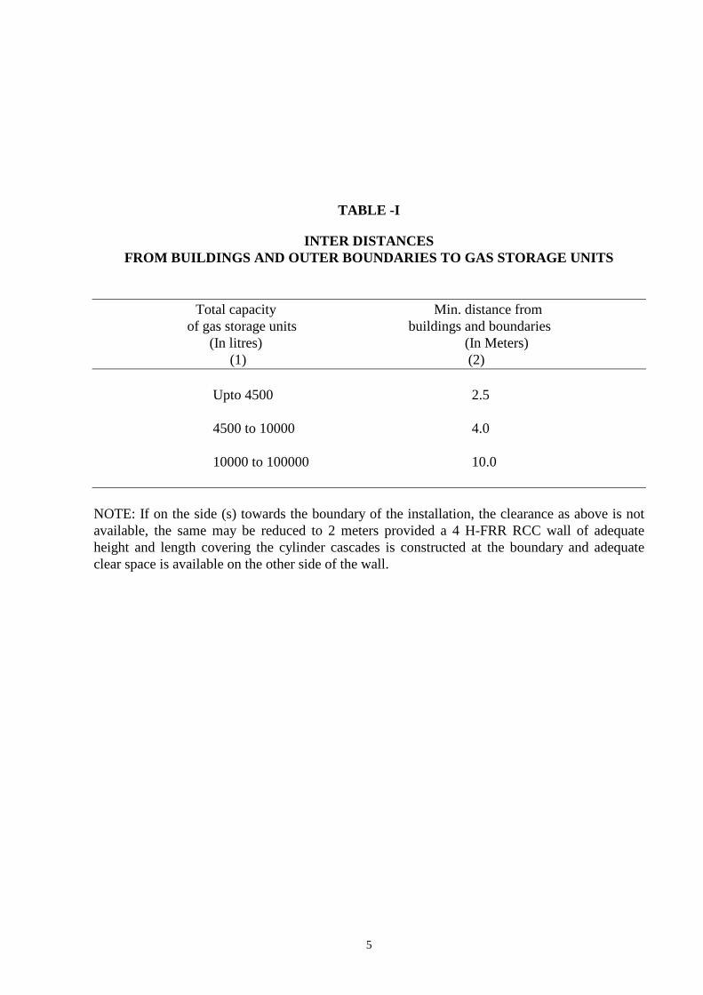
TABLE -I
INTER DISTANCES FROM BUILDINGS AND OUTER BOUNDARIES TO GAS STORAGE UNITS
Total capacity Min. distance from of gas storage units buildings and boundaries
(In litres) (In Meters) (1) (2)
Upto 4500 2.5
4500 to 10000 4.0
10000 to 100000 10.0
NOTE: If on the side (s) towards the boundary of the installation, the clearance as above is not available, the same may be reduced to 2 meters provided a 4 H-FRR RCC wall of adequate height and length covering the cylinder cascades is constructed at the boundary and adequate clear space is available on the other side of the wall.

6
TABLE - II
INTER DISTANCES BETWEEN VARIOUS FACILITIES OF NATURAL GAS HANDLING AT
INSTALLATION --------------------------------------------------------------------------------------------------------------------------------- Distance From 1 2 3 4 5 6 7 (in meters) --------------------------------------------------------------------------------------------------------------------------------- 1. CNG - 3 2 3 6 6 T-1
Compressor (Min-3) 2. CNG 3 - 2 4 6 4 -Do-
Dispensing Unit 3. Storage 2 2 - T-1 T-1 T-1 -Do-
cascade (Min-6) (Min-4) 4. Outer 3 4 T-1 - 6 4 -Do- boundary wall/ CLF 5 MS/HSD 6 6 T-1 6 - 6 -Do-
dispenser (Min-6) 6. Vent of 6 4 T-1 4 6 - 6
MS/HSD u/g (Min-4) storage tanks
7. Filling point of ----------------------------T-1(Min-3)------------------------- 6 - MS/HSD ------------------------------------------------------------------------------------------------------------------------------- NOTES : i) T-I denotes Table-I ii) Distances shown as “ – ” shall be any
distance necessary for operational convenience.
iii) A suitable curbing platform shall be
provided at the base of the dispensing unit to prevent vehicles from coming too near the unit.
iv) A CNG cascade having cylinders of total
water capacity not exceeding 4500 liters can be mounted on top of the compressor super structure. The assembly shall observe 3-meter clearance around and also from the dispensing unit. This can be reduced to 2 meter as per Note- I of Table – I.
7.0 CNG STORAGE SYSTEM
(Static) :
7
7.1 The cascade having horizontal cylinders and
sited parallel to other cascade, cylinder fittings should be arranged so that they do not face cylinder fittings of other cascade.
7.2 Cylinder installed horizontally in a cascade
shall be separated from another cylinder in the cascade by a distance of not less than 30 mm.
7.3 Cascade with horizontal cylinders shall
have the valves fitted on the same side within the cascade opposite to the refuelling point and arranged in a manner that any gas leakage is discharged upwards.
7.4 Cascade/bulk units shall be installed on a
firm, compacted, well-drained non-combustible foundation. This foundation may be in the form of a plinth with the raised edge at 2 M from the front and sides of the cascade forming a kerb upto which vehicles should be permitted. The cascade shall be securely anchored to prevent floating in case flooding is anticipated.
7.5 Gas storage facility shall be protected from
the effects of the weather by a roof or canopy designed to facilitate the dispersion of free or escaped gas and shall not permit gas to be trapped.
7.6 Adequate means shall be provided to
prevent the flow or accumulation of flammable or combustible liquids under containers such as by grading, pads or diversion curbs.
8.0 CNG STORAGE SYSTEM
(Mobile)
8.1 Only dedicated trailer, truck or any other vehicle to be used for transportation of CNG storage units. These units should have lugs fitted for lifting and in no case magnetic device to be used for lifting purposes.
8.2 The vehicle with the cascade thereon, shall
be placed with easy access and egress on a low platform or hard compacted ground, which shall extend to atleast another one meter on all sides and this platform or hard ground shall be under a light roof or canopy as described in 7.5 above.
8.3 For other inter-distances refer Table I, II,
above.
8.4 The trailers/ vehicle carrying CNG should
be made immovable by application of brake and wheel choke prior initiation of filling or dispensing operation.
9.0 CYLINDERS 9.1 The cylinders and their fittings for CNG use
shall be designed, manufactured, tested including hydrostatic stretch test at a pressure in full conformity to IS:7285 and Gas Cylinder Rules, 1981, considering the maximum allowable operating pressure of 250 kg/ Sq.cm.g.
9.2 These cylinders are to be permanently and
clearly marked for “CNG only” and also labelled "CNG ONLY" in letter at least 25 mm high in contrasting colour in a location which shall be visible after installation.
9.3 The cylinder shall be fabricated from steel.
However, cylinders with composite materials may be considered after the establishment of its suitability and approval of the Chief Controller of Explosives.
9.4 The cylinders shall be re-examined and re-
tested every five years and in accordance with Gas Cylinder Rules, 1981 by a competent person with due markings. No cylinder shall be used which has not been duly re-tested as indicated.
9.5 Cylinders shall be painted white to reduce
solar heating effect and protect it from atmospheric corrosion.
10.0 CNG PIPING 10.1 All rigid piping, tubing, fittings and other
piping components shall conform to the recommendations of ANSI B 31.3. All the elements of piping should be designed for the full range of pressures, temperatures and loading to which they may be subjected with a factor of safety of at least 4 based on the minimum specified tensile strength at 20 deg. C.
10..2 Gaskets, packing and any other materials used
shall be compatible with natural gas and its service conditions.
10.3 All the piping and tubing shall have minimum
turns with adequate provision for expansion, contraction, jarring, vibration and settling.

8
Exterior piping may be either buried with suitable corrosion protection or installed 30 cm. above the ground level with supports and protection against mechanical and corrosive damage.
10.4 Rigid pipelines shall have welded joints
between their respective components. 10.5 All the piping and tubing shall withstand a
pressure equal to that of safety relief device and tested accordingly after assembly. The testing to be done by inert gas, in case natural gas is used the suitable safety measures to be adhered to.
10.6 VALVES 10.6.1 A minimum of four shut off valves shall be
fitted between the gas storage unit and vehicle refuelling filling nozzle as explained below:
a) Each CNG storage unit to have quick
action isolation valve in the steel supply pipe immediately adjacent to such storage unit to enable isolation of individual storage unit. These valves shall be within fencing of storage unit.
b) Master shut off valve with locking
arrangement in close position, shall be installed in steel outlet pipe outside but immediately adjacent to the gas storage unit to isolate all downstream equipment from the gas storage unit. This valve shall be outside the fencing.
c) A quick action emergency and isolation
shut off valve shall be installed near dispensing unit with easy approach and to remain closed when refuelling is not being done.
d) A vehicle refuelling shut off valve shall
be installed for each flexible vehicle refuelling hose to control the refuelling operation and shall have venting provision to allow for the bleeding of the residual high pressure gas after refuelling is complete.
10.6.2 All these valves and other elements of piping shall be suitable for the full range of pressure and temperature to which they may be subjected. These valves are to have permanent marking for service rating etc.
11. 0 CNG HOSES
11.1 Internally braided, electrically continuous,
non-metallic and metallic hoses resistant to corrosion and suitable to the natural gas service may be used for CNG service in the downstream of emergency and isolation shut off valve.
11.2 These flexible hoses and their connections
shall be suitable for most severe pressure and temperature service condition expected with a burst pressure of at least four times the maximum working pressure.
11.3 The flexible hoses with their connections
shall be tested after assembly and prior to use to atleast two times the working pressure and also tested to a pneumatic pressure of atleast 400 bar under water. Thereafter, all the hoses shall be examined visually and tested for leaks with soapsuds or equivalent at an interval not exceeding one year. Hoses shall be rejected and destroyed in the event of any leakage. These tests are to be recorded and such records shall be available at installations at all times.
11.4 Flexible hoses shall have permanent marking
indicating the manufacturer's name/ identification, working pressure and suitability for use with CNG.
12. 0 PRESSURE GAUGES 12.1 Every CNG storage unit including each
cascade or bulk storage tank shall be provided with a suitable pressure gauge directly in communication with them.
12.2 The CNG storage unit shall have an opening
not to exceed 1.4-mm diameter at the connection where pressure gauge is mounted.
12.3 The pressure gauge shall have dial graduated
to read approximately double the operating pressure but in no case less than 1.2 times the pressure at which pressure relief valve is set to function.
12.4 All pressure gauges in the installation shall be
tested and calibrated atleast once a year and records maintained.
13. 0 COMPRESSOR STATION 13.1 The piping and its fittings upto the battery
limit of CNG installation shall conform to ANSI B 31.8 or equivalent.

9
13.2 Compressor shall be designed for use in CNG
service and for the pressures and temperature to which it may be subjected under normal operating conditions conforming to API 618/ API 813 or equivalent standard and Flame proof electric motor and associated fittings should conform to IS:2148 suitable for class I division I group II area.
13..3 Compressor shall be fitted with the following
minimum devices : a) Pressure relief valves on inlet and all stages
to prevent pressure build up above the predetermined set point.
b) High discharge temperature shut down c) High cooling water temperature switch
fitted to cooling water return line to shut the compressor in the event of a fault.
d) High, inlet, inter stage & discharge
pressures shut down. e) Low lube oil pressure shut down f) Low cooling water flow switch fitted to the
cooling water return line to shut the compressor in the event of fault.
g) A remote isolation switch for emergency
shut down to be provided with manual reset at control panel.
13.4 Compressor shall be provided atleast the
following clear and permanent markings readily accessible and easy to read in the installed position :
a) Manufacturer's name b) Model c) Serial No./ month & year of
manufacture d) Certificate of approval no. e) Rated capacity (cubic meter per hour) f) Operating speed (RPM) g) Required driving power( in kW)
h) Maximum & minimum supply pressures i) Maximum outlet pressure j) Certification for Natural Gas use
13..5 A compressor and its all fittings shall be
tested for compliance of relevant standard suitable for CNG use by a competent person/ agency prior to installation.
14. 0 PRESSURE RELIEF DEVICE 14.1 Safety Relief Devices may consist of either
burst disc or safety relief valve and should conform to the requirements of OISD-STD-132.
14.2 Safety relief devices shall be installed with
unobstructed full size discharge to a safe place on bulk tanks and cylinders in the vertical position with suitable rain caps. These devices should have their outlet arranged in a manner so that in case of emergency a high-pressure gas escapes from these should not directly hit on operators/ persons in the close vicinity.
14.3 Cylinder should have safety relief devices
fitted in conformity to the Gas Cylinder Rules.
14.4 Piping shall be protected by safety relief
devices in conformity to OISD-STD-132. 14.5 Safety relief valves shall have a locking
arrangement to prevent tempering by unauthorised persons. Any adjustments to the safety relief valve shall be made by manufacturer or a competent person. These valves should have a permanent tag indicating pressure setting, date of re-setting/ setting and capacity.
14.6 All safety relief devices shall be tested at
least once a year for proper operations and records to be maintained.
14.7 All the safety relief devices shall have
manufacturer's permanent marking indicating following :
a) Set pressure to start discharge b) Discharge capacity in CuM / min. 14.8 No shut off valves shall be installed between
the safety relief device and the gas storage unit or bulk tank.
14..9 All natural gas devices not otherwise
specifically mentioned shall be constructed and installed to provide a safety equivalent to that other parts of the system.
14.10 Gas detectors interlocked with compressor
cut out switch in the electrical system of the compressor are to be installed which would automatically switch off the unit in case of major gas leak.

10
15.0 ELECTRICAL EQUIPMENT 15.1 All electrical wiring and equipment, gas
storage dispensing unit located in hazardous area Division I and II shall be in accordance with the Indian Electricity Rules, Gas Cylinder Rules, IS:5572 (Part 1), NFPA - 52.
15.2 The earthing at the installation, protection
against ignition arising out of static, lightning and stray currents shall be as described in OISD-STD-110 and further maintained as per the guidelines given in OISD-STD-137.
16.0 SAFETY AT VEHICLE FOR
REFUELLING 16.1 The vehicles shall have approved type of
CNG kit fitted in accordance with the guidelines of Ministry of Surface Transport, Govt. of India by an authorised workshop and such workshop should issue a fitness certificate to the vehicle for its suitability for CNG use. Such certificate should be always carried by the driver of the vehicle at all times.
16.2 Driver of the vehicle should also carry the
record showing the last examination of the vital parts of the system fitted in the vehicle for CNG use and their next due date for such examination. The details must include the test periodicity of cylinder, pressure relief devices, pressure gauges, piping etc.
16.3 The cylinder with valves and connected
facilities fitted in the vehicle shall be in accordance with Gas Cylinder Rules. These cylinders should be subjected to hydraulic test at least once every five years.
16.4 Every vehicle using CNG fuel system should
display "CNG" labels prominently in compliance to Central Motor Vehicle Rules .
17.0 DISPENSING UNIT 17.1 Dispensers shall be installed on a suitable
foundation observing the minimum safety distances etc. as given in 6.0 above. Dispensing unit to be protected against possible damage by vehicular movement.
17.2 The flexible hoses fitted on the dispenser
shall be mechanically and electrically continuous. The design, material and construction of hoses shall be suitable for
CNG and shall withstand not less than four times the maximum working pressure of the system.
17..3 The dispensing unit shall be of a type
approved by the Chief Controller of Explosives / Statutory Authorities .
18. 0 CNG REFUELLING INTO
VEHICLES 18.1 The vehicle refuelling shall be done by an
experienced operator duly certified by the oil / gas company having control over the refuelling station.
18.2 The operator of the CNG dispensing unit
shall check the following prior to refuelling the gas :
a) The driver of the vehicle is carrying updated
history record as given in clause 16.
b) There is no smoking, naked flame or any other source of ignition within six meter of the refuelling point.
c) There is no leakage in the CNG fuel system
reported by the driver of the vehicle.
d) The fuel connection is in good condition and matches the dispensers filling nozzle. Fuel connection shall be tight without any leakage.
e) The engine is switched off, hand brake is
firmly applied, the vehicle parked in gear or in " P " with automatic transmission.
f) No passenger remains inside the vehicle .
18.3 Detailed precautions (refer 18.2) and
procedure of refuelling to be displayed near the dispensing unit and strictly followed by the operator.
18.4 The operator of the dispensing machine
should not leave the vehicle being refuelled. 18.5 The cylinder on the vehicle shall not be
charged in excess of maximum allowable working pressure at normal temperature for the cylinder.
18.6 Before the refuelled vehicle is driven away
from the dispensing point the operator and driver should ensure that there are no

11
apparent gas leaks either on the vehicle or on the dispensing point that may have been caused through faulty filling or the faulty action of connecting or disconnecting.
18.7 Warning signs with the words "STOP
VEHICLE", "NO SMOKING", "NO OPEN FLAME PERMITTED", "FLAMMABLE GAS", shall be displayed at dispensing station and compressor areas. The location of the signs shall be such that these are prominently visible from each point of transfer/ operation.
19. 0 FIRE PROTECTION 19.1 Fire fighting facilities need to be carefully
planned after considering the availability of municipal fire tenders etc. However, atleast the following Portable fire extinguishers shall be positioned:
Location Type of Extinguishers Dispensing Unit 1 x 10 kg. DCP Compressor ( on-line) 1 x 10 kg. DCP (mother station) 1x 75 kg DCP CNG Storage 1 x 10 kg. DCP Cascade refuelling 1 x 10 kg. DCP area MCC/ Electrical { 1 x 4.5 kg CO2 Installation { 25 Sq.M floor area 19.2 Any other flammable materials not specified
in this standard in the CNG installation shall be stored in a non-flammable chamber with a minimum safety distance of 15 M from compressor station/ MCC/ electrical installation.
19.3 All approaches to machines, compressors,
storage facilities and work places shall be free from obstacles, so that they are readily accessible in an emergency.
19.4 The electrical installations shall be inspected
by a competent Electrical Inspector as per IE Rules and compliance shall be made as pointed out in the inspection. Records shall be maintained for all periodic inspections.
19.5 The flameproof characteristics of electrical
equipment shall be checked through visual checks, condition of gasket, completeness and
tightness of bolts, glands and as recommended by manufacturer's test certificates.
19.6 No unauthorised additions or modifications
of the service station whether temporary or permanent shall be taken up.
19.7 Proper illumination to be ensured for all
operating and non-operating areas. 19.8 All electrical maintenance at the Automotive
Station shall be undertaken by licensed electrical technician under supervision of authorised person.
19.9 Each installation shall have minimum two
numbers hand held explosive meter in working conditions at all times.
20. 0 EMERGENCY PLAN AND
PROCEDURE 20.1 The Oil Company having control over the
refuelling station shall draw an operational emergency plan in consultation with adjoining establishments and local authorities e.g. fire brigade, police, and other District Emergency Authorities etc. for the following circumstances :
a) Loss of or interruption to the gas supplies
due to leaks or failure of pipeline b) Over-odorisation of the gas c) Major failure of CNG fittings d) Accidents or other emergencies, which
can affect the CNG refuelling, station e) Civil emergencies f) Any other risk arising from the existence
or use of the CNG refuelling station. 20.2 The above emergency plan shall be
disseminated amongst all personnel involved and ensured that they understand their roles and responsibilities in the event of an emergency.
20.3 The operator of the refuelling station should
have close liaison with Fire Service, the Police, the Municipal Authorities and the person supplying gas to CNG facility.
20.4 Important telephone numbers for emergency
use shall be displayed prominently. 20.5 Means of communication shall be always at
the disposal of the Incharge of the installation on 24 hours basis.

<< Back Home Next >>