
* of 69 Design for Cast and Molded Parts Team: Terese Bertcher Larry Brod Pam Lee Mike Wehr.
153
* of 69 Design for Cast and Molded Parts Team: Terese Bertcher Larry Brod Pam Lee Mike Wehr
-
Upload
skyler-gatley -
Category
Documents
-
view
216 -
download
0
Transcript of * of 69 Design for Cast and Molded Parts Team: Terese Bertcher Larry Brod Pam Lee Mike Wehr.

* of 69
Design for Cast and Molded PartsTeam: Terese Bertcher
Larry Brod
Pam Lee
Mike Wehr

* of 69
Lecture updates
Revisions & Edits provided by: Seamus Clark, Scott Leonardi, Gary Meyers, Joe Torres, Beatriz Dhruna, John Fraser, Craig Jozsa, Dwayne Mattison, Darcy McClure, Kevin O’Callaghan, Norm Opolsky, Henry Gasahl, Rolf Glaser

* of 69
Lecture Topics
• Basic Casting Design Guidelines• Injection Molding Process• Gating Considerations• Case Study – Corvette Brake Pedal• Case Study – M1 Abrams Tank
* of 69
Basic Casting Design Guidelines1. Visualize the Casting
2. Design for Soundness
3. Avoid Sharp Angles & Corners
4. Minimize the Number of Sections
5. Employ Uniform Sections
6. Correctly Proportion Inner Walls
7. Fillet All Sharp Angles
8. Avoid Abrupt Section Changes
9. Maximize Design of Ribs & Brackets
10. Avoid Using Bosses, Lugs & Pads

* of 69
Visualize the Casting
• It is difficult to follow section changes and shapes from blueprint.
• Create a model to scale or full size to help designer to:– See how cores must be designed, placed or omitted– Determine how to mold the casting– Detect casting weaknesses (shrinks / cracks)– Determine where to place gates and risers– Answer questions affecting soundness, cost and
delivery
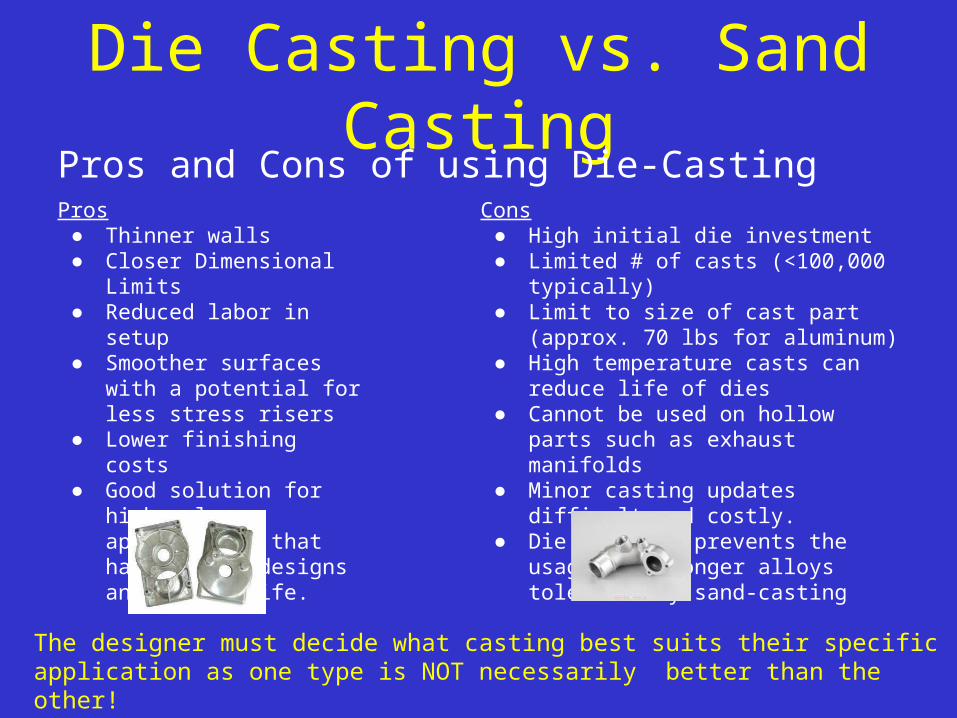
Die Casting vs. Sand CastingPros and Cons of using Die-CastingPros
● Thinner walls● Closer Dimensional Limits● Reduced labor in setup● Smoother surfaces with a
potential for less stress risers● Lower finishing costs● Good solution for high
volume applications that have stable designs and design life.
Cons● High initial die investment● Limited # of casts (<100,000 typically)● Limit to size of cast part (approx. 70 lbs for
aluminum)● High temperature casts can reduce life of
dies● Cannot be used on hollow parts such as
exhaust manifolds● Minor casting updates difficult and costly.● Die casting prevents the usage of stronger
alloys tolerated by sand-casting
The designer must decide what casting best suits their specific application as one type is NOT necessarily better than the other!

* of 69
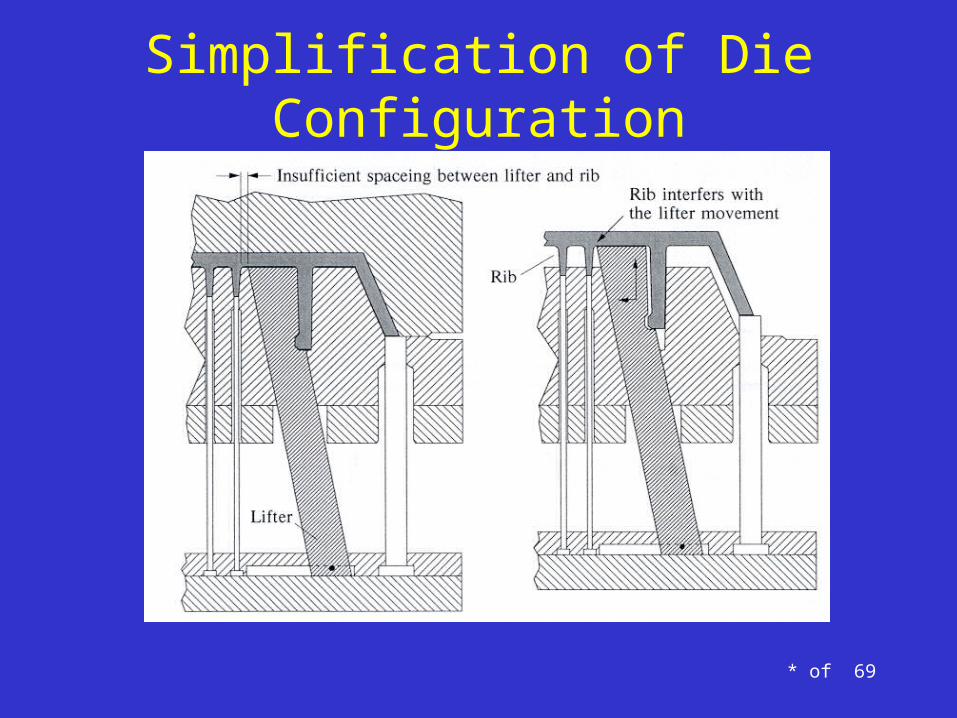
Simplification of Die Configuration
Core
Cavity
Part
Die Opening Direction
Die Opening Direction

* of 69
Simplification of Die Configuration
Add a chamfer to the part
Core
Cavity
Die Opening Direction
Die Opening Direction

* of 69
Simplification of Die Configuration
Support plate is stationary. It pushes lifter to the left as ejector plate moves upward. Lifter moves away from undercut portion of snap
Ejector pin pushes the part out of the core as the lifter slides away from the snap undercut.
* of 69
Simplification of Die Configuration

* of 69
Basic Casting Design Guidelines1. Visualize the Casting
2. Design for Soundness
3. Avoid Sharp Angles & Corners
4. Minimize the Number of Sections
5. Employ Uniform Sections
6. Correctly Proportion Inner Walls
7. Fillet All Sharp Angles
8. Avoid Abrupt Section Changes
9. Maximize Design of Ribs & Brackets
10. Avoid Using Bosses, Lugs & Pads

* of 69
Design for Soundness
• Most metals, alloys, and plastics shrink when they solidify• Design components so that all parts increase in dimension
progressively to areas where feeder heads (risers) can be placed to offset shrinkage
• Disguise areas of shrinkage when unavoidable• The mold and pattern should be made larger than the casting by the
amount of shrinkage• Shrinkage of casting varies not only with material but also with shape,
thickness, casting temperature, mold temperature and mold strength • Thicker areas will cool slower than thinner areas. Areas of transition
between thick and thin (ribs, walls, embosses, etc) will be prone to sink marks. Different tool shops and different materials will require a certain rib-to-wall thickness ratio.

Design for Soundness
• The table below shows an average amount of shrinkage for important cast metals
* *

* of 69
Design Rules: Disguising Sink Marks

* of 69
Basic Casting Design Guidelines1. Visualize the Casting
2. Design for Soundness
3. Avoid Sharp Angles & Corners
4. Minimize the Number of Sections
5. Employ Uniform Sections
6. Correctly Proportion Inner Walls
7. Fillet All Sharp Angles
8. Avoid Abrupt Section Changes
9. Maximize Design of Ribs & Brackets
10. Avoid Using Bosses, Lugs & Pads

* of 69
Avoid Sharp Angles & Corners
• When two or more sections conjoin, mechanical weakness is induced at the junction interrupting free cooling (most common defect in casting design).– Replace sharp angles with radii and minimize heat and
stress concentration– In cored parts avoid designs without cooling surfaces– A rounded junction offers a more uniform distribution
of strength

* of 69
Design Rules:Corners & Radii
Good Corner Design Incorrect Corner Design
Incorrect Corner Design Incorrect Corner Design
• Generous radius
• Uniform wall thickness
• Smooth flow transition
• Very sharp radii
• High stress concentration
• Sharp flow transition
• Inside / outside radius mismatch
• Non-uniform wall thickness
• Non-uniform flow transition
• Outside corner and inside radius
• Non-uniform wall thickness
• Non-uniform flow transition
• Shrinkage stress / voids / sinksSink

* of 69
Basic Casting Design Guidelines1. Visualize the Casting
2. Design for Soundness
3. Avoid Sharp Angles & Corners
4. Minimize the Number of Sections
5. Employ Uniform Sections
6. Correctly Proportion Inner Walls
7. Fillet All Sharp Angles
8. Avoid Abrupt Section Changes
9. Maximize Design of Ribs & Brackets
10. Avoid Using Bosses, Lugs & Pads

* of 69
Minimize the Number of Sections
• A well designed casting brings the minimum number of sections together at one point.
• Staggering sections (where possible)– Minimizes hot spot effects– Eliminates weakness– Reduces distortion
• Where staggering sections is not possible use a cored hole through the center of the junction.– Helps to speed solidification– Helps to avoid hot spots

* of 69
Basic Casting Design Guidelines1. Visualize the Casting
2. Design for Soundness
3. Avoid Sharp Angles & Corners
4. Minimize the Number of Sections
5. Employ Uniform Sections
6. Correctly Proportion Inner Walls
7. Fillet All Sharp Angles
8. Avoid Abrupt Section Changes
9. Maximize Design of Ribs & Brackets
10. Avoid Using Bosses, Lugs & Pads

* of 69
Employ Uniform Sections
• Thicker walls will solidify more slowly.– This means they will feed solidifying thinner walls.– Results in shrinkage voids in the thicker walls
• Goal is to design uniform sections that solidify evenly.– If this is not possible, all heavy sections should be
accessible to feeding from risers.

* of 69
Design Rules: Wall Uniformity
Original Part Design• Very thick wall sections
• Non-uniform wall thickness
• Sharp inside and outside radii
Improved Part Design• Thinner wall sections
• More uniform wall thickness
• Inside and outside radii (when possible)

* of 69
Basic Casting Design Guidelines1. Visualize the Casting
2. Design for Soundness
3. Avoid Sharp Angles & Corners
4. Minimize the Number of Sections
5. Employ Uniform Sections
6. Correctly Proportion Inner Walls
7. Fillet All Sharp Angles
8. Avoid Abrupt Section Changes
9. Maximize Design of Ribs & Brackets
10. Avoid Using Bosses, Lugs & Pads
* of 69
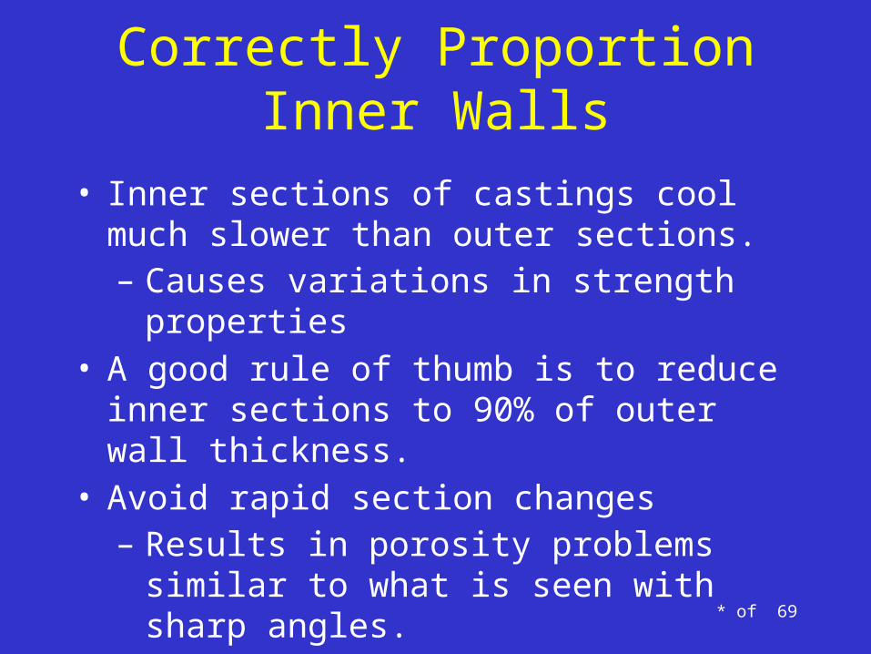
Correctly Proportion Inner Walls
• Inner sections of castings cool much slower than outer sections.– Causes variations in strength properties
• A good rule of thumb is to reduce inner sections to 90% of outer wall thickness.
• Avoid rapid section changes– Results in porosity problems similar to what is
seen with sharp angles.
* of 69
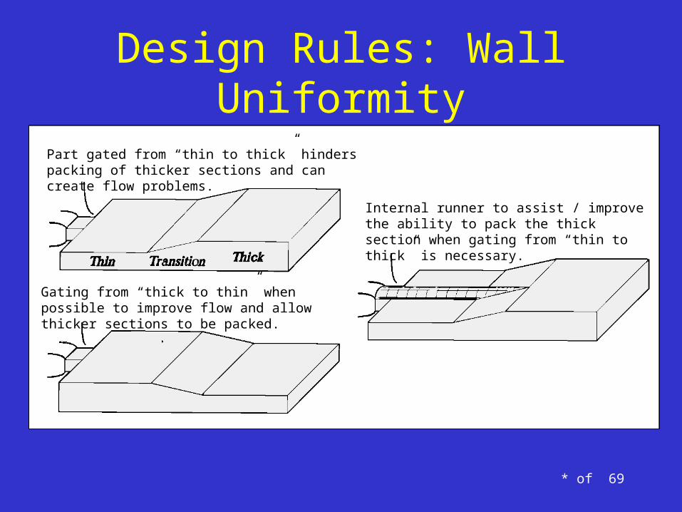
Design Rules: Wall Uniformity
Part gated from “thin to thick” hinders packing of thicker sections and can create flow problems.
Gating from “thick to thin” when possible to improve flow and allow thicker sections to be packed.
Internal runner to assist / improve the ability to pack the thick section when gating from “thin to thick” is necessary.

* of 69
Correctly Proportion Inner Walls
• Whenever complex cores must be used, design for uniformity of section to avoid local heavy masses of metal.
• The inside diameter of cylinders and bushings should exceed the wall thickness of castings.– When the I.D. is less than the wall it is better to cast the
section as a solid.– Holes can be produced by cheaper and safer methods
than with extremely thin cores
* of 69
Basic Casting Design Guidelines1. Visualize the Casting
2. Design for Soundness
3. Avoid Sharp Angles & Corners
4. Minimize the Number of Sections
5. Employ Uniform Sections
6. Correctly Proportion Inner Walls
7. Fillet All Sharp Angles
8. Avoid Abrupt Section Changes
9. Maximize Design of Ribs & Brackets
10. Avoid Using Bosses, Lugs & Pads
Fillet All Sharp Angles
• Fillets (rounded corners) have three functional purposes:– To reduce the stress concentration in a casting in
service– To eliminate cracks, tears and draws at re-entry angles– To make corners more moldable by eliminating hot
spots– Improves flow of material
• The number of different size fillet radii used in a pattern should be the minimized

* of 69
Fillet All Sharp Angles
• Large fillets may be used with radii equaling or exceeding the casting section.– Commonly used to fulfill engineering stress
requirements– Reduces stress concentration
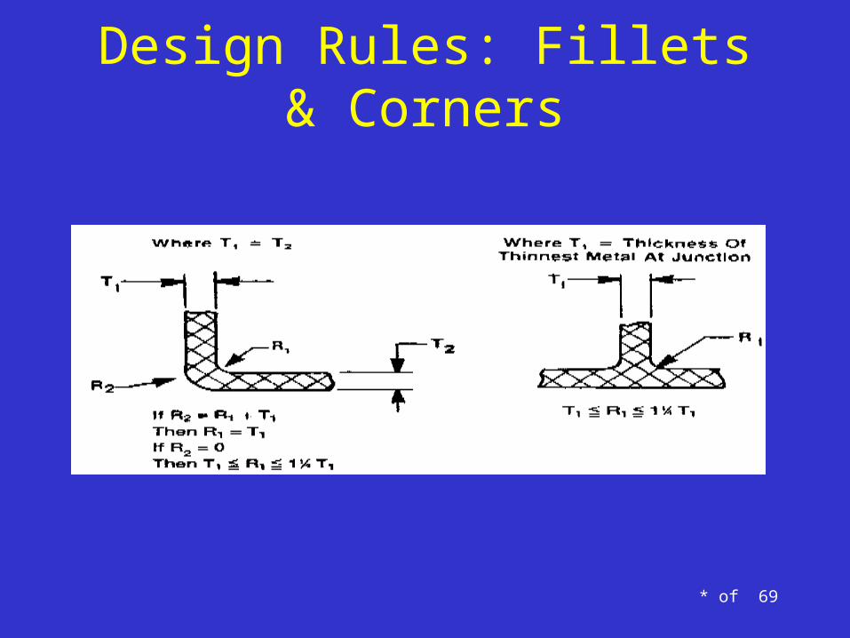
• Note: Fillets that are too large are undesirable – the radius of the fillet should not exceed half the thickness of the section joined.

* of 69
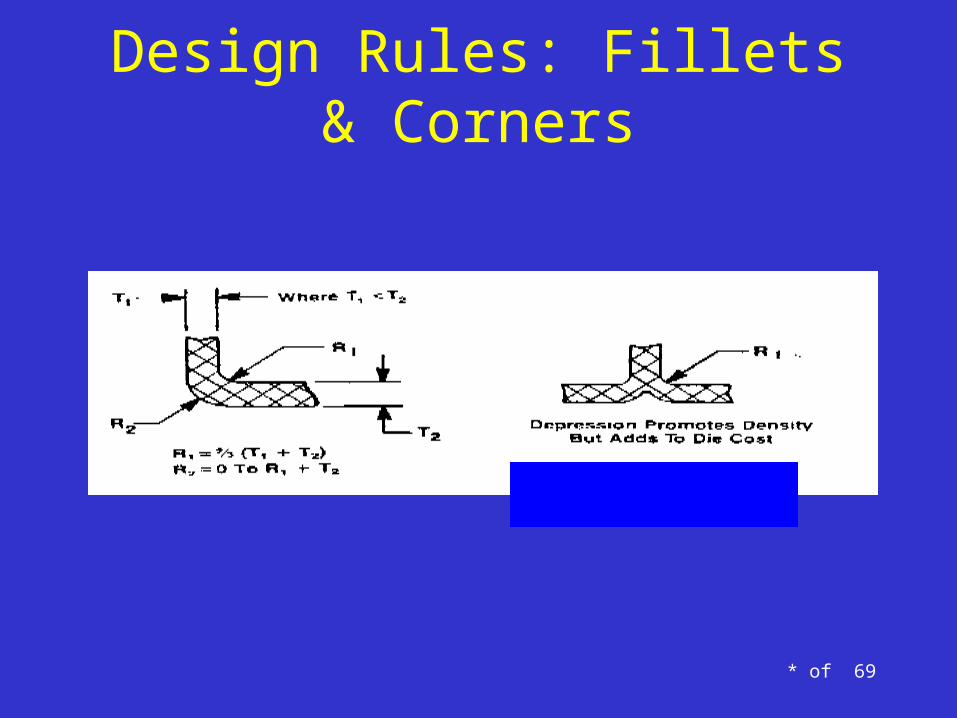
Fillet All Sharp Angles
• Tips to avoid a section size that is too large at an “L”, “V” or “Y” junction.
• For an “L” junction :– Round an outside corner to match the fillet on the
inside wall. (If this is not possible the designer must make a decision as to which is more important: Engineering design or possible casting defect)
• For a “V” or “Y” junction:– Always design so that a generous radius eliminates
localization of heat.
* of 69
Design Rules: Fillets & Corners
* of 69
Design Rules: Fillets & Corners

* of 69
Design Rules: Fillets & Corners

* of 69
Basic Casting Design Guidelines1. Visualize the Casting
2. Design for Soundness
3. Avoid Sharp Angles & Corners
4. Minimize the Number of Sections
5. Employ Uniform Sections
6. Correctly Proportion Inner Walls
7. Fillet All Sharp Angles
8. Avoid Abrupt Section Changes
9. Maximize Design of Ribs & Brackets
10. Avoid Using Bosses, Lugs & Pads

* of 69
Avoid Abrupt Section Changes
• The difference in relative thickness of adjoining sections should not exceed a ratio of 2:1.
• With a ratio less than 2:1 the change in thickness may take on the form of a fillet.
• Where this is not possible consider a design with detachable parts.

* of 69
Avoid Abrupt Section Changes
• With a ratio greater than 2:1 the recommended shift for the change in thickness should take on the form of a wedge.– Note: wedge-shaped changes in wall thickness should
not taper more than 1 in 4.
• Where a combination of light and heavy sections is unavoidable, use fillets and tapered sections to temper the shifts.

* of 69
Design Rules: Section Changes
Wall Thickness Transitions
Tapered Transition
Gradual TransitionStepped Transition
Core out thicker areas where possible
Poor Design
Better
Best
* of 69
Basic Casting Design Guidelines1. Visualize the Casting
2. Design for Soundness
3. Avoid Sharp Angles & Corners
4. Minimize the Number of Sections
5. Employ Uniform Sections
6. Correctly Proportion Inner Walls
7. Fillet All Sharp Angles
8. Avoid Abrupt Section Changes
9. Maximize Design of Ribs & Brackets
10. Avoid Using Bosses, Lugs & Pads

* of 69
Maximize Design of Ribs & Brackets
• Ribs are only preferable when the casting wall cannot be made strong or stiff enough on its own.
• Ribs have two functions:– They increase stiffness– They help to reduce weight
• Common mistakes that make ribs ineffective:– Too shallow– Too widely spaced
* of 69
Maximize Design of Ribs & Brackets
• The thickness of the ribs should be approximately 80% of the adjoining thickness and should be rounded at the edge.
• The design preference is for ribs to be deeper than they are thick.
• Ribs should solidify before the casting section they adjoin.
• The space between ribs should be designed such that localized accumulation of metal is prevented.
• Preferably the ribs connect the attachment to the loading point.

* of 69
Design Rules:Rib Dimensions
General Guidelines for Rib Dimensions*
•Component wall thickness: h
•Draft per side(0): 0.5º ⇔ 1.5º
•Rib height (L): ≤ 5h (typically 2.5⇔3.0h)
•Rib spacing (on center): ≥ 2h ⇔ 3h
•Base radius (R): ≥ 0.25h ⇔ 0.40h
•Rib thickness (t): 0.4 ⇔ 0.8h
*Exact rib dimensions are material specific

* of 69
Design Rules:Rib Wall Thickness
Correct Proportions
Radius (fillet)
Sink Mark
Shrinkage VoidsExcessive
Radius
Part Wall
Rib
Excessive Rib Wall
Thickness

* of 69
Maximize Design of Ribs & Brackets
• Generally, ribs in compression offer a greater safety factor than ribs in tension.
• Exception: Castings with thin ribs in compression may require design changes to provide necessary stiffening and avoid buckling.
• Thin ribs should be avoided when joined to a heavy section or they may lead to high stresses and cracking

* of 69
Maximize Design of Ribs & Brackets
• Avoid cross ribs & ribbing on both sides of a casting– Cross ribbing creates hot spots and makes feeding
difficult– Alternative is to design cross-coupled ribs in a
staggered “T” form.
• Avoid complex ribbing– Complicates molding, hinders uniform solidification
and creates hot spots

* of 69
Maximize Design of Ribs & Brackets
• Ribs meeting at acute angles may cause molding difficulties, increase costs and aggravate the risk of casting defects
• “Honeycombing” often will provide increased strength and stiffness without creating hot spots

* of 69
Design Rules: Rib Manufacturability

* of 69
Design Rules: Rib Design

* of 69
Maximize Design of Ribs & Brackets
• Brackets carrying offset loads introduce bending moments, localized and in the body of the casting.
• Tips to avoid this problem:– Taper “L” shaped brackets and make the length of
contact with the main casting as ample as possible.– Brackets may frequently be cast separately and then
attached, simplifying the molding.

* of 69
Maximize Design of Ribs & Brackets
• A ribbed bracket will offer a stiffness advantage, but avoid heat concentration by providing cored openings in webs and ribs.– The openings should be as large as possible– The openings should be consistent with strength and
stiffness
• Avoid rectangular-shaped cored holes in ribs or webs.– Use oval-shaped holes with the longest dimension in
the direction of the stresses

* of 69
Recommended Configurations
May complicate die construction
External ribs may cause poor distribution of stresses
May complicate die construction
Sharp corners, small radii
H ≤ T H > T core out underside
Good distribution of stresses
Sharp corners, small radii, little draft
Generous draft and fillets, angular transitions
Ribs inside, good distribution of metals for all purposes.
* of 69
Avoid Using Bosses, Lugs & Pads
• Bosses and pads can have adverse effects on castings:– They increase metal thickness– They create hot spots– They can cause open grain or draws
• If they must be incorporated into a design you should blend them into the casting by tapering or flattening the fillets.

* of 69
Reducing Heavy Masses & Die Simplification
A
a c
B
b
d

* of 69
Reducing Heavy Masses & Die Simplification
A B C
a
dcb

* of 69
Reducing Heavy Masses & Die Simplification
A B

* of 69
Basic Casting Design Guidelines1. Visualize the Casting
2. Design for Soundness
3. Avoid Sharp Angles & Corners
4. Minimize the Number of Sections
5. Employ Uniform Sections
6. Correctly Proportion Inner Walls
7. Fillet All Sharp Angles
8. Avoid Abrupt Section Changes
9. Maximize Design of Ribs & Brackets
10. Avoid Using Bosses, Lugs & Pads

* of 69
Avoid Using Bosses, Lugs & Pads
• The thickness of bosses and pads should be less than the thickness of the casting section they adjoin but thick enough to permit machining without touching the casting wall.
• Exception: Where a casting section is light the following should be used as a guide:
Casting Length: < 1.5’ Min. Boss Height: .25”
1.5’< X < 6’ .75”
> 6’ 1.00”

* of 69
Avoid Using Bosses, Lugs & Pads• Bosses should not be used in casting design when
the surface to support bolts may be obtained by milling or countersinking.
• A continuous rib instead of a series of bosses will permit shifting hole location.
• Where there are several lugs and bosses on one surface, they should be joined to facilitate machining.– A panel of uniform thickness will simplify machining– Make the walls of a boss at uniform thickness to the
casting walls
* of 69
Design Rules: Boss Design
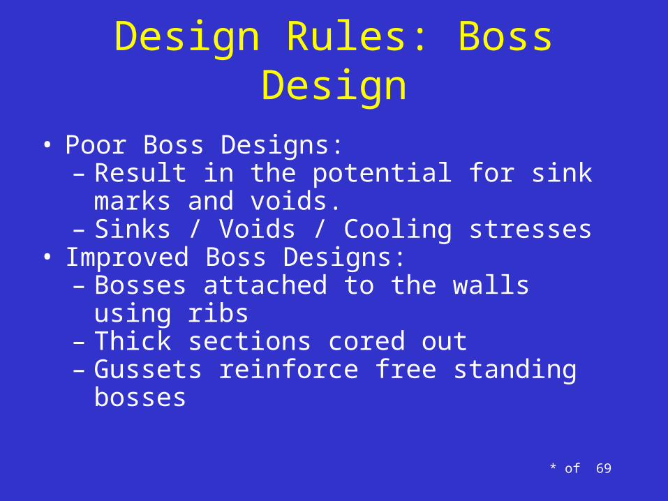
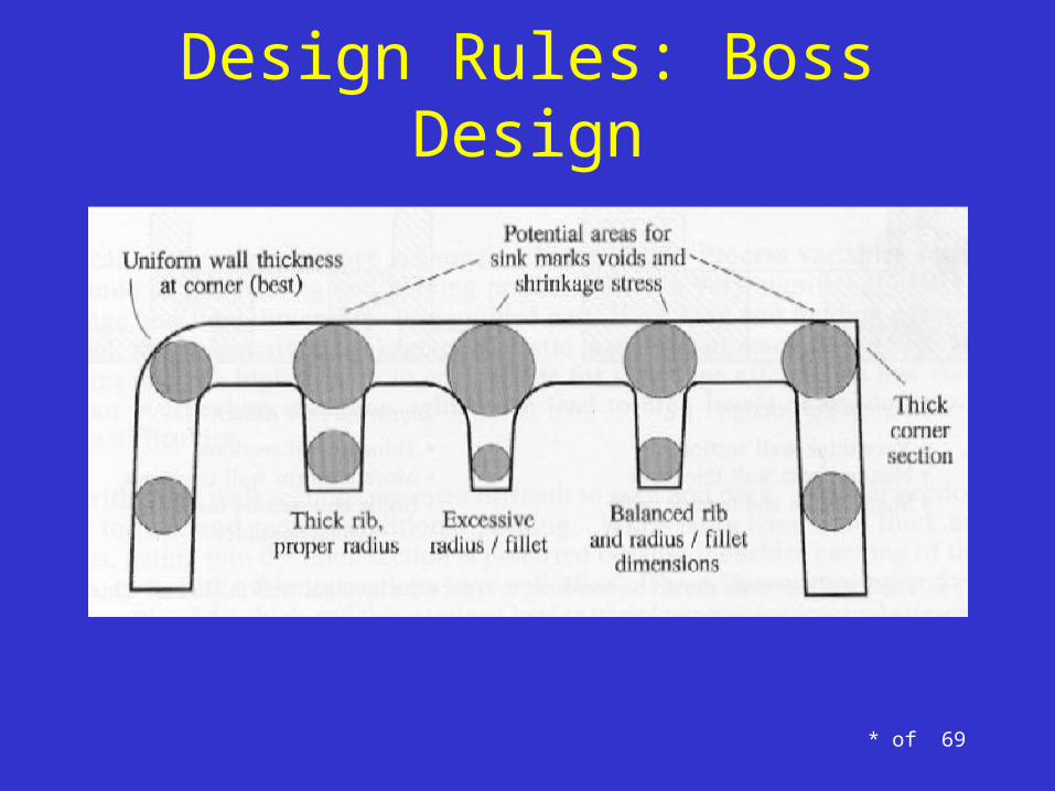
• Poor Boss Designs:– Result in the potential for sink marks and voids.– Sinks / Voids / Cooling stresses
• Improved Boss Designs:– Bosses attached to the walls using ribs– Thick sections cored out– Gussets reinforce free standing bosses
* of 69
Design Rules: Boss Design

* of 69
Lecture Topics
• Basic Casting Design Guidelines• Injection Molding Process• Gating Considerations• Case Study – Corvette Brake Pedal• Case Study – M1 Abrams Tank

* of 69
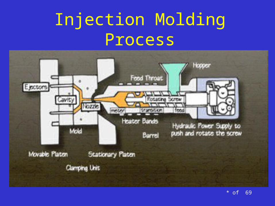
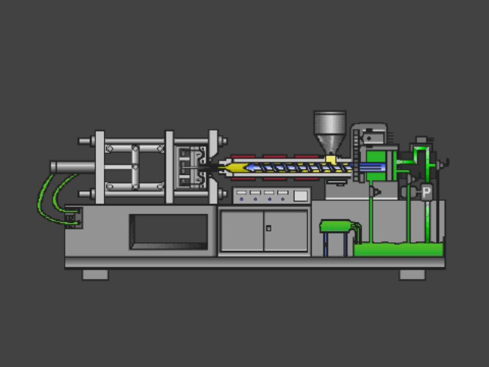
• The injection molding process is the most commonly used plastic molding process. It is a high speed, automated process for producing parts from both thermoplastic and thermosetting plastic materials, and is used to create a large variety of products with complex shapes and sizes.
• Advantages: o high production rates (multi-cavity tooling, low cycle times)o repeatable high toleranceso low labor costo minimal scrap losseso little need to finish parts after molding
Injection Molding Process
* of 69
Injection Molding Process

* of 69
Injection Molding Process

* of 69
Injection Molding Process
Conventional Injection Molding
Gas Assisted Injection MoldingGas Assisted Injection Molding
Sink
Gas Channels
* of 69
Video Clip of Injection Molding Process
Rev. 11-2001 * of 69

Rev. 11-2001 * of 69

Rev. 11-2001 * of 69

Rev. 11-2001 * of 69

51 of 69
Gas-Assisted Injection Molding Process

Common Defects with Injection Molding• Knit lines - Caused by the melt-front flowing around an object
standing proud in a plastic part as well as at the end of fill where the melt-front comes together again. Can be minimized or eliminated with a mold-flow study when the mold is in design phase.
• Sink marks – Excessive material thickness (in local area) or rib thickness too large for wall thickness.
• Flash - Parting line on the tool is damaged, too much injection speed/material injected, clamping force too low. Parting lines should
be placed in non-visible locations, especially in class-A surfaces. • Dealing with these: Die draw, parting lines, boss locations, can all be
assessed while the interior surfaces are still in the clay design phase. Suggestion is to add a case study around an IP or Console clay in the studio development phase, and how it can be used to assess injection molding capabilities.
* of 69

Impact of Design Guidelines on Molding Process
Steel / Product Conditions Risk if violated• Minimum Wall Thickness 2.5mm • Increase Cavity Pressures
• Short Shots
• Wall stock designed with variation of more than +/- 15% from normal wall
• Product stress caused by uneven pack and cooling• Inconsistent gloss levels due to “hot spots”
• 40% of normal wall to be maximum rib thickness at wall stock intersection
• Sink marks• Gloss variation
• 1 degree per side minimum draft on ribs • Sinking in mold• Drag marks
• Distortion of “A” surface
• Ribs deeper than 17mm without ability to insert and / or vent mold at bottom of ribs
• Gas traps and /or short shot• Gas Burns
• Steel erosion at bottom of rib due to “Off Gassing”
• Minimum Rib thickness of 1mm at base of rib • Short shots due to inability to fill thin sections • Increase cavities pressures
• Over packing of part causing inaccurate shrink
• Injection Pressures in excess of 12,000 psi, as shown on mold flow (Mold flow pressures are typically 15% / 25%
lower than actual machine pressures in production)
• Excess stress to cavity or core steel possible causing metal fatigue leading to failure
• Inconsistent cavity fill and pack on older equipment
Rev. 11-2001 72 of 69

Steel / Product Conditions Risk if violated• Hot drop quantity and / or positioning that limit mold cooling • Internal stress in plastic
• Gloss variations do to lack of cooling • Increase cycle time
• Standing “Fingers of Steel” that do not maintain a 1:1 height to base ratio (i.e. 10mm high x 10mm square or Dia. Base)
• Possible failure of steel do to fatigue caused by molding pressure or shutoff loads
• Minimum draft of 1.5 degrees for an un-textured surfaces and 1 degree / .001” (.025mm) of Texture Depth for grained
surfaces
• Drag marks• Damage surface
• Grain scuffing
• Class “A” surface parting lines should be designed with deliberate offset to facilitate matching and graining
• As a little as .001” mismatch of steel is visible on class “A” surface
• Texture Mask (Shut-Off protection) is visible
• Split parting lines on Class “A” surface should be designed into a flat surface, if the parting line is designed to a tangent
of a radius the surface will deteriorate rapidly
• Parting line deterioration• “Frog Hair” Flash
• Heavy Surface Flash
• Deep “V” product designs that create “notch” conditions in injection mold (a deep “V” is defined as anything less than 60 degrees included angle and with a depth of more than
twice the width
• Cracked or broken molds• Catastrophic mold failure with loss of production
• Tolerances that are tighter than are repeatable in normal mold cycles. General rule of thumb is +/- 0.5mm first
200mm than +/- 0.0025mm per mm of length or width after
• Molded product that may not meet capability requirements
Rev. 11-2001 73 of 69
Impact of Design Guidelines on Molding Process

Injection Mold Design Considerations
• Min draft on all faces → 0.5° (without grain)• Draft as low as 0.3° for deep features (without
grain)• Gate into thick regions of the part• Maintain acceptable rib-to-wall ratio (to avoid
sink)• Use action in tooling to avoid undercuts• Consider draft angle requirements for intended
grain (if parts are to be grained)

Rib Design Guidelines - Injection Molding
• Rib thickness at base should be no more than 40-50% of wall thickness to avoid sink marks
• Rib height should be set to achieve 1mm MIN thickness at peak (avoid “razor edge”)

Tooling Action - Injection Molding
• Action (i.e. slides/lifters) should be used to avoid undercut
Red hatched lines represent undercut area when using the die draw direction specified. Adding a slide to form this feature will alleviate the undercut issue.
Example:”Witness lines” can be seen on the part in the area where a slide was used to form the clip tower

Part Graining - Injection Molding
• Each grain type has draft requirements for grain depth (i.e. 60%, 80%, 100%, etc.). 100% depth requires maximum draft angle for all grained surfaces.
• General requirement = 1° draft / 1 micrometer of grain depth
Molded parts can be grained to improve appearance and reducegloss level.

Advanced Injection Molding Techniques
Pulsed Cooling–Traditional techniques of cooling have circulated fluid through the mold at a constant rate, and the local surface temp of the mold was therefore somewhat uncontrolled.–Advanced pulse cooling controls the temperature of the mold on a localized basis by opening and closing valves which controls the mass flow of the fluid and therefore the rate of heat transfer out of the mold.
Traditional Cooling Pulsed Cooling

Advanced Injection Molding TechniquesInduction Heating
– Traditionally, the temperature of the mold during the filling cycle was a function of the temperature of the resin, the facility, the temperature and flow of the coolant, and length of time since the last shot.
–With the use of induction heating, the mold temperature can be raised above the temperature of the resin before and during the filling phase.
–This can have many benefits including:• lower injection pressure and clamping requirements• improved flow lengths• reduction of internal part stresses• reduction or elimination of weld lines,• Reduction of jetting, silver streaks, or sink marks.
Simple Induction heating of rod

Advanced Injection Molding TechniquesLive-Feed Injection Molding
–The live-feed injection molding process applies oscillating pressure at multiple polymer entrances to cause the melt to oscillate
–The action of the pistons keeps the material in the gates molten while different layers of molecular or fiber orientation are being built up in the mold due to solidification
–This process provides a means of making simple or complex parts that are free from voids, cracks, sink marks, and weld-line defects

Advanced Injection Molding TechniquesMulti-Material Molding – There are several types
–Once Step Process• Co-Injection• Sandwich molding
–Multi-Step Process• Overmolding• Two-shot molding

Advanced Injection Molding TechniquesMulti-Material Molding – Sandwich
–Sandwich molding is typically used to mold multi-layered plastic packaging articles having a laminated wall structure. Each layer is typically passed through a different annular or circular passageway in a single nozzle structure and each layer is partially, sequentially, injected through the same gate. Ref US Pat #7,559,756

Advanced Injection Molding TechniquesMulti-Material Molding – Co-Injection
–Co-Injection molding is similar to Sandwich molding, however in co-injection the materials may not come out in layers as in Sandwich.
–The same basic manufacturing principle applies – Muli-Materials are simultaneously input into a single mold, and combined together to form one part
Multiple Sprues & Materials

Advanced Injection Molding TechniquesMulti-Material Molding – Over-Molding
–Overmolding (or two-shot molding) is for parts where more than one material is needed (i.e. plastic housing molded around metal plate)
–In these processes, only part of a product is molded in one material, and that molded piece is manipulated so the second material can be
molded around, over, under, or through it to complete the final part. –Overmolding is differentiated from two-shot in the fact that a part
that is overmolded may be done in a completely separate operation, or may be made of a material other than plastic, so it is not a two shot process, but still an overmold.
Overmolded Knife – Polymer Handle

Advanced Injection Molding TechniquesMulti-Material Molding – Two Shot
–Two shot molding is very similar to overmolding, only the molding is done within a single manufacturing process.
–There are several processes of two shot molding, shown below is an indexing process. Shot one is completed in cavity A, then the parts are rotated, part A is transferred into cavity B. After Shot B is complete, the final part is ejected.

Advanced Injection Molding TechniquesMulti-Material Molding – Combined Processes
–In this example, Overmolding and Two Shot molding are combined• Polymer C is overmolded to the Metal Ring• Polymer B is overmolded to the Metal Ring / Polymer C• Polymer A is then overmolded to complete the assembly
Polymer A
Metal Ring
Polymer C
Polymer B

Advanced Injection Molding TechniquesMulti-Material Molding – Combining processes
–In the diagram below, this shows how an overmolded (2 shot) part and a sandwich molded part are brought together via a hot plate weld.
•http://www.ptonline.com/articles/hot-cold-thermal-cycling-of-injection-molds-heats-up•http://www.mddionline.com/article/innovative-injection-molding-techniques-medical-industry•http://www.dc.engr.scu.edu/cmdoc/dg_doc/develop/process/molding/b2500004.htm•http://www.google.com/imgres?imgurl=http://www.pulsecooling.com/images/Animation/anipc2.gif&imgrefurl=http://www.pulsecooling.com/&usg=__HL8G3m2axMCqeFZKRUmDJGX69sA=&h=346&w=376&sz=193&hl=en&start=1&zoom=1&tbnid=YNyGFifrjpBOsM:&tbnh=112&tbnw=122&ei=LrUT57gL4XK2AWN9rSzDw&prev=/search%3Fq%3Dpulsed%2Bmould%2Bcooling%26um%3D1%26hl%3Den%26safe%3Dstrict%26sa%3DN%26gbv%3D2%26tbm%3Disch&um=1&itbs=1•http://en.wikipedia.org/wiki/File:Induction_heating_of_bar.jpg•http://www.4spe.org/plastics-encyclopedia/coinjection-molding•US Patent # - 7,559,756 •http://www.google.com/imgres?imgurl=http://www.cascadecartsolutions.com/images/coinjection.jpg&imgrefurl=http://www.cascadecartsolutions.com/tech/coinjection.htm&usg=__540EJ9vnJyNdZ3ShnV6B84QUpt8=&h=325&w=415&sz=20&hl=en&start=1&sig2=mEUWMnmI8lTzc-qHJSR4-A&zoom=1&tbnid=jSFc15hKryTnmM:&tbnh=98&tbnw=125&ei=5MXUT_ikMuPW2gWs1YSSDw&prev=/search%3Fq%3Dcoinjection%26hl%3Den%26safe%3Dstrict%26tbm%3Disch&itbs=1•http://www.google.com/imgres?imgurl=http://www.dc.engr.scu.edu/cmdoc/fp_doc/fill_pix/5coinjec/begn_out/coresurf/coresurf.gif&imgrefurl=http://www.dc.engr.scu.edu/cmdoc/fp_doc/f5co1.frm.html&usg=__syxxBxDtl1bxO12cJhfmLVHQWiA=&h=331&w=419&sz=6&hl=en&start=4&sig2=0ECD13yWj-YpoGZafQ9U3g&zoom=1&tbnid=9AK7427uPt4e0M:&tbnh=99&tbnw=125&ei=xs3UT-j8GIPY2gXe6PibDw&prev=/search%3Fq%3Dcoinjection%2Bmolding%26um%3D1%26hl%3Den%26safe%3Dstrict%26gbv%3D2%26tbm%3Disch&um=1&itbs=1•http://www.glstpes.com/pdf/om.pdf•http://www.google.com/imgres?imgurl=http://terpconnect.umd.edu/~skgupta/M3T/Figure%25202_7.jpg&imgrefurl=http://terpconnect.umd.edu/~skgupta/M3T/MSM.html&usg=__tEFlwu65EfKLt71FB2vGDKedj8Y=&h=506&w=541&sz=65&hl=en&start=7&sig2=uWJC6LxXy3UXxtMX5tnF_w&zoom=1&tbnid=fp8FAASVFpxolM:&tbnh=123&tbnw=132&ei=9tPUT6yeGsaA2QXm0_CfDw&prev=/search%3Fq%3D2%2Bshot%2Bmolding%26um%3D1%26hl%3Den%26safe%3Dstrict%26sa%3DN%26gbv%3D2%26tbm%3Disch&um=1&itbs=1
Material BMaterial A
Hot Plate Weld JointMaterial B
Material CMaterial B
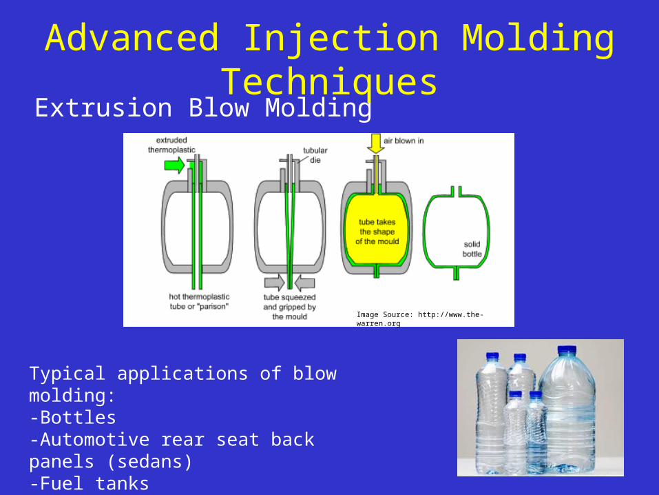
Advanced Injection Molding TechniquesExtrusion Blow Molding
Image Source: http://www.the-warren.org
Typical applications of blow molding:-Bottles-Automotive rear seat back panels (sedans)-Fuel tanks -HVAC ducts

• Mold parting is vertical.• All metal in gates, risers and casting cavities are contained
within the flaskless sand molds.• There are casting size and weight limitations due to the
hydrostatic pressure built up within the mold.• There is reduced flexibility for gating and risers.
*
DISAMATIC Casting Process
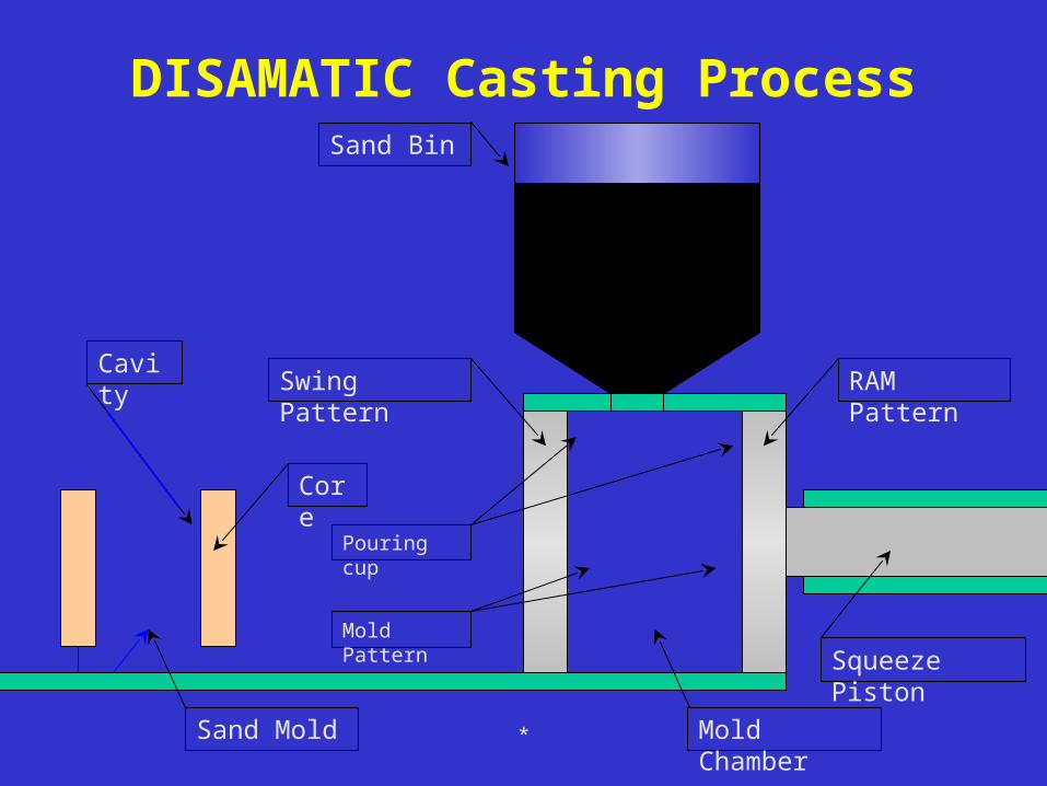
Squeeze Piston
Swing Pattern RAM Pattern
Sand Bin
Mold ChamberSand Mold
Core
Cavity
Pouring cup
Mold Pattern
DISAMATIC Casting Process
*
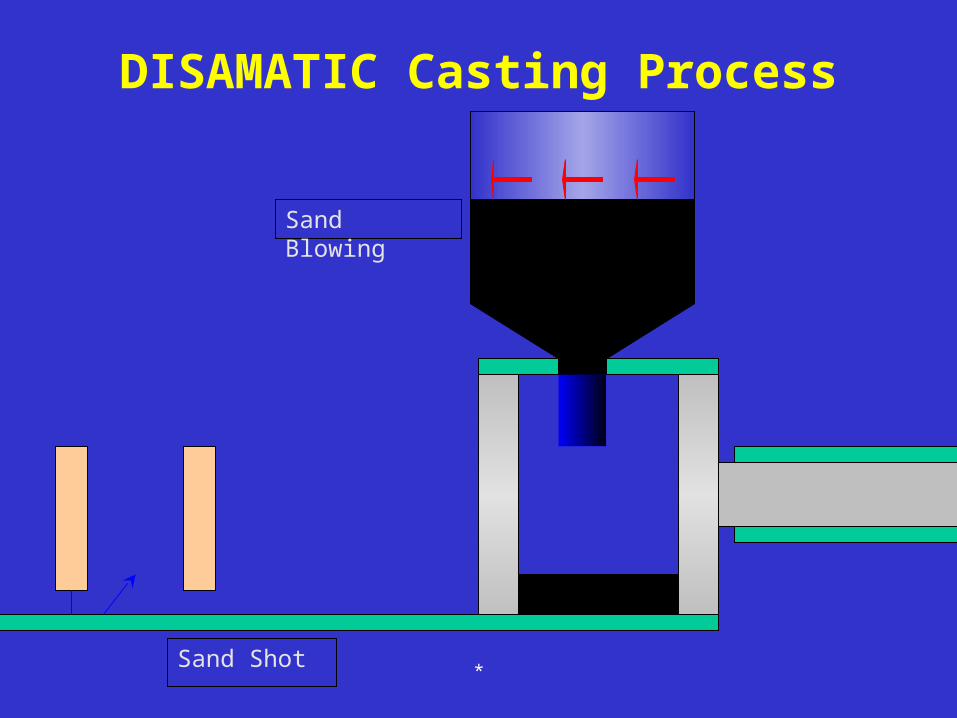
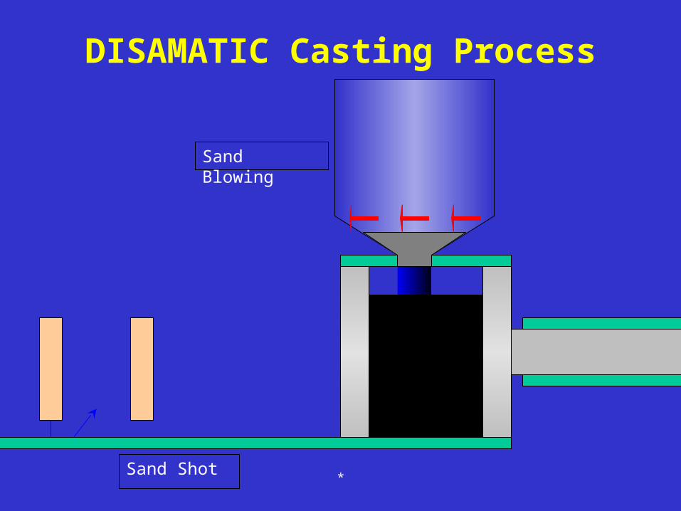
DISAMATIC Casting Process
Sand Shot
Sand Blowing
*

DISAMATIC Casting Process
Sand Blowing
*Sand Shot

DISAMATIC Casting Process
Sand Blowing
*Sand Shot

DISAMATIC Casting Process
Sand Blowing
*Sand Shot
DISAMATIC Casting Process
Sand Blowing
*Sand Shot

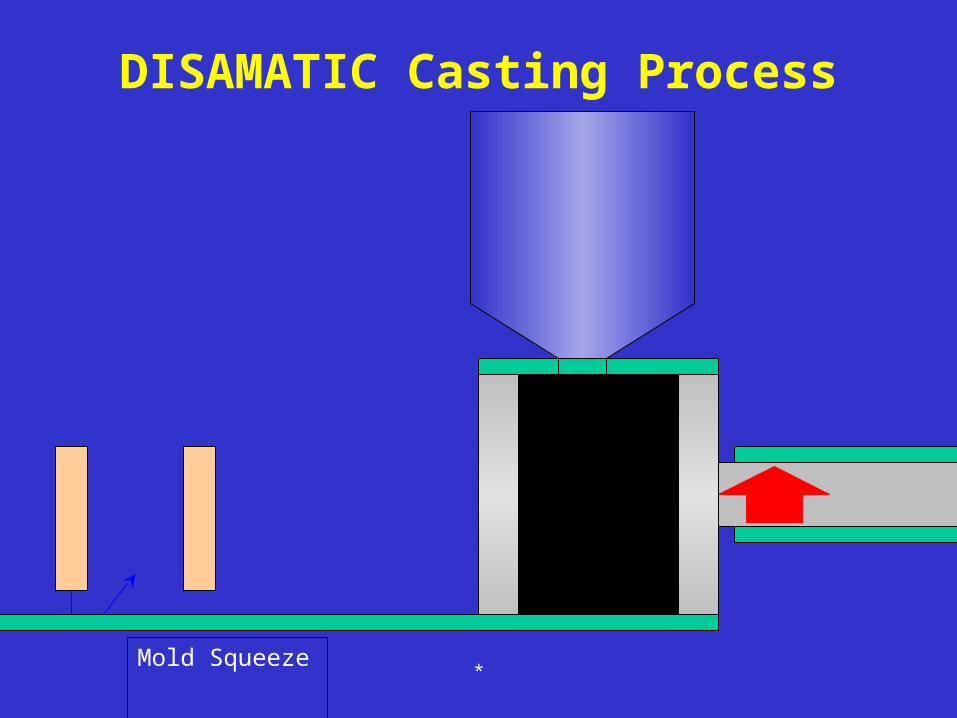
DISAMATIC Casting Process
Mold Squeeze*
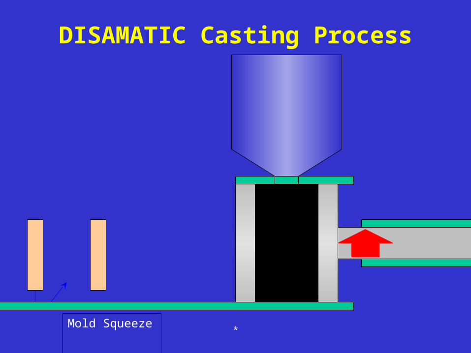
DISAMATIC Casting Process
*Mold Squeeze

DISAMATIC Casting Process
*Mold Squeeze
DISAMATIC Casting Process
*Mold Squeeze

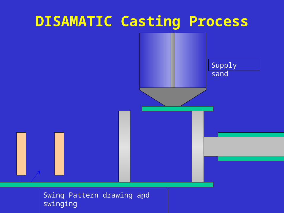
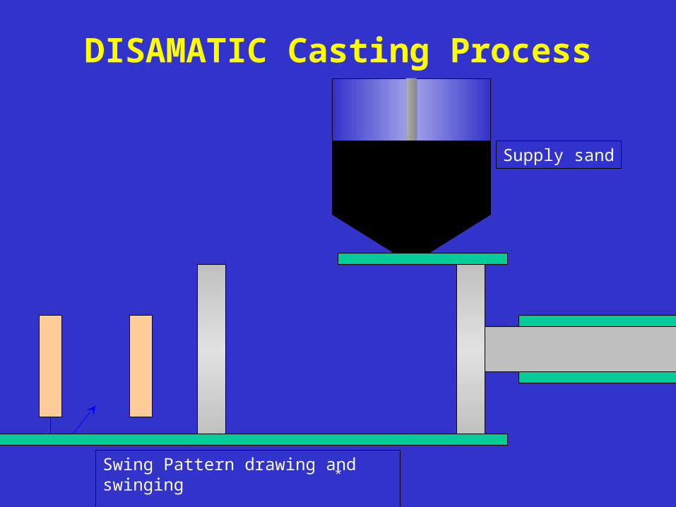
DISAMATIC Casting Process
Supply sand
*Swing Pattern drawing and swinging

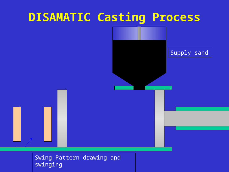
DISAMATIC Casting Process
Supply sand
*Swing Pattern drawing and swinging
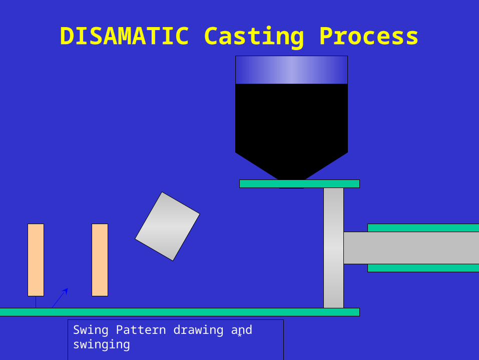
DISAMATIC Casting Process
Supply sand
*Swing Pattern drawing and swinging

Supply sand
DISAMATIC Casting Process
*Swing Pattern drawing and swinging

Supply sand
DISAMATIC Casting Process
*Swing Pattern drawing and swinging
Supply sand
DISAMATIC Casting Process
*Swing Pattern drawing and swinging
Supply sand
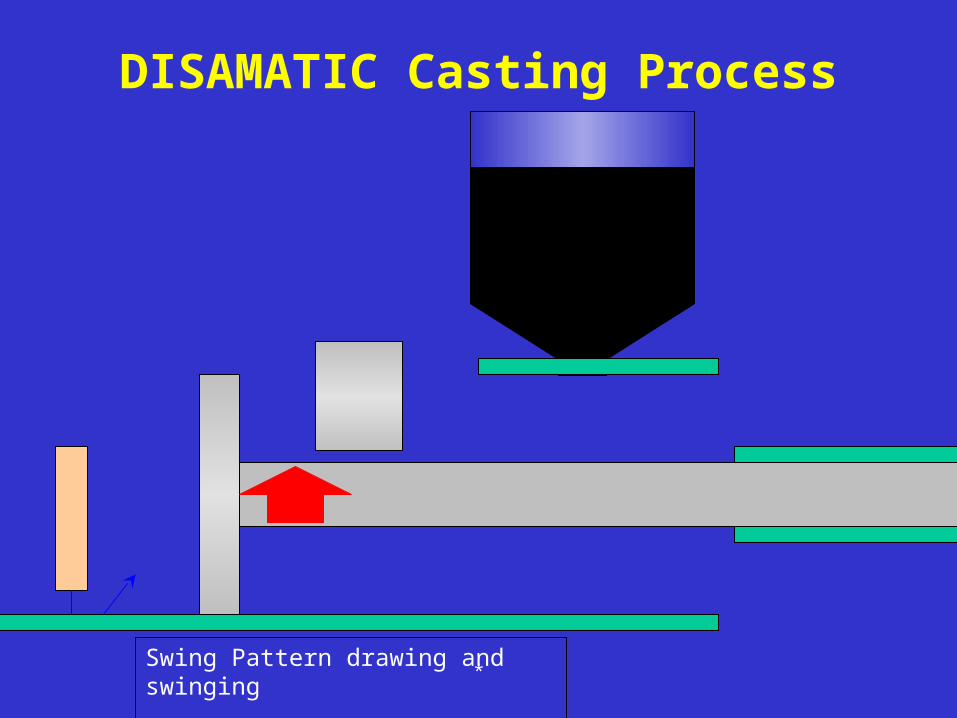
DISAMATIC Casting Process
*Swing Pattern drawing and swinging

DISAMATIC Casting Process
*Swing Pattern drawing and swinging
DISAMATIC Casting Process
*Swing Pattern drawing and swinging

DISAMATIC Casting Process
*Swing Pattern drawing and swinging

DISAMATIC Casting Process
*Swing Pattern drawing and swinging

DISAMATIC Casting Process
*Swing Pattern drawing and swinging

DISAMATIC Casting Process
*Swing Pattern drawing and swinging

DISAMATIC Casting Process
*Swing Pattern drawing and swinging

DISAMATIC Casting Process
*Swing Pattern drawing and swinging
DISAMATIC Casting Process
*Swing Pattern drawing and swinging
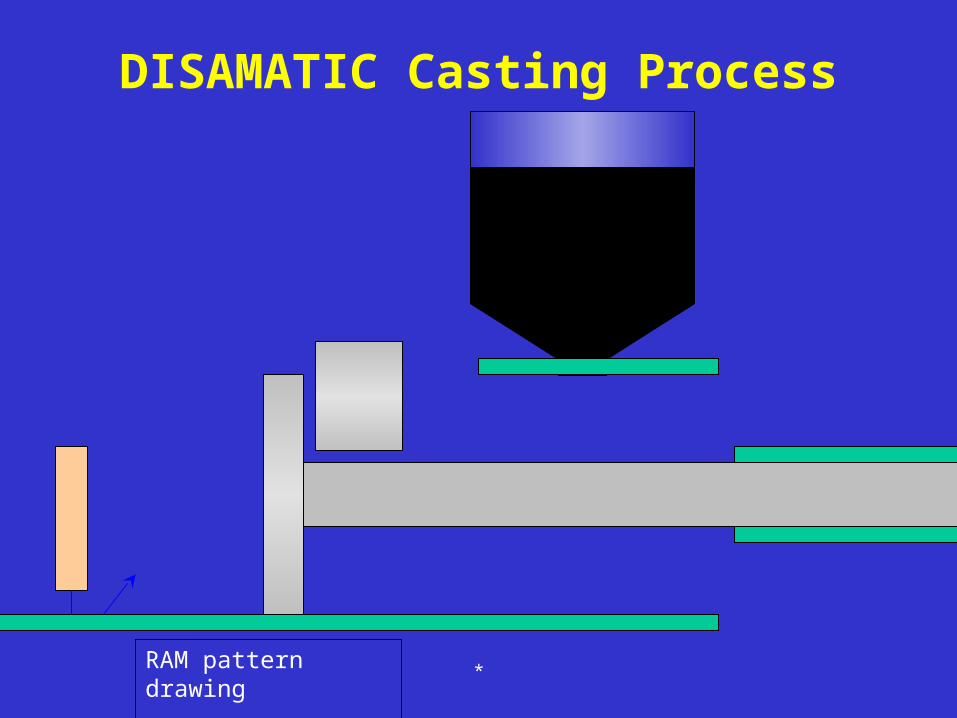
RAM pattern drawing
DISAMATIC Casting Process
*

DISAMATIC Casting Process
*RAM pattern drawing

DISAMATIC Casting Process
*RAM pattern drawing

DISAMATIC Casting Process
*RAM pattern drawing
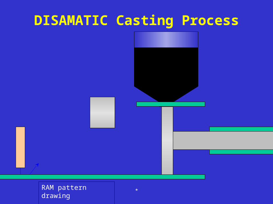
DISAMATIC Casting Process
*RAM pattern drawing

DISAMATIC Casting Process
*RAM pattern drawing

DISAMATIC Casting Process
*RAM pattern drawing
DISAMATIC Casting Process
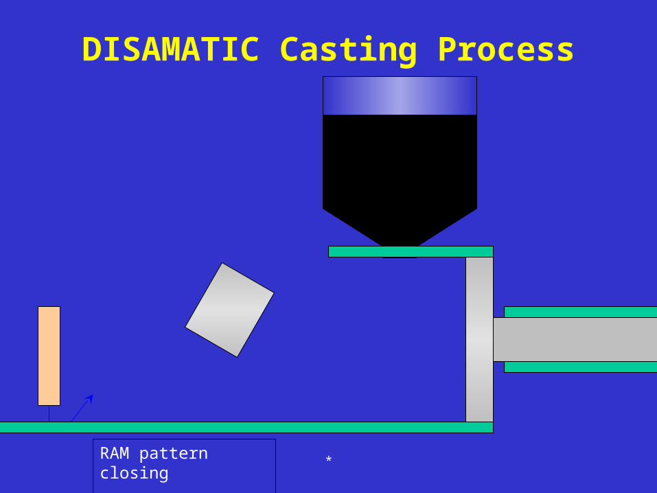
*RAM pattern closing

DISAMATIC Casting Process
*RAM pattern closing

DISAMATIC Casting Process
*RAM pattern closing

DISAMATIC Casting Process
*RAM pattern closing

DISAMATIC Casting Process
*RAM pattern closing

DISAMATIC Casting Process
*RAM pattern closing

Core Mask
Core
DISAMATIC Casting Process
*Core Setting

DISAMATIC Casting Process
*Core Setting

DISAMATIC Casting Process
*Core Setting

DISAMATIC Casting Process
*Core Setting
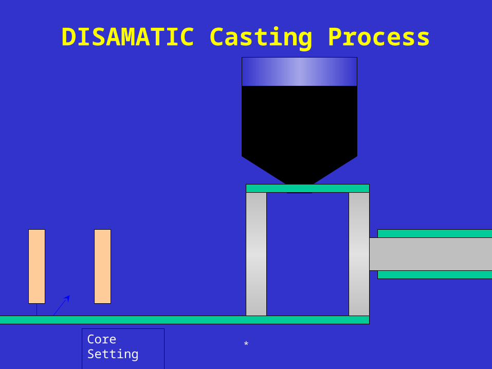
DISAMATIC Casting Process
*Core Setting

Cycle time : 10 - 15 seconds/mold
DISAMATIC Casting Process
*

* of 69
Lecture Topics
• Basic Casting Design Guidelines• Injection Molding Process• Gating Considerations• Case Study – Corvette Brake Pedal• Case Study – M1 Abrams Tank

*
Gating Location and Constraint Considerations
Spoke Gating (2 spokes) Diaphragm or disk gateSpoke Gating (4 spokes)

* of 69
Gating Considerations
Cavity
Spruce Puller (and cold slug well)
GateCore
Runner
PartSpruce

* of 69
Gating Considerations
Two plate single cavity mold
Three plate mold configuration (multi cavity)
Single parting
line
Primary spruce
Pin Gate
Parting Line 1
Parting Line 2
Secondary Spruce
Spruce Gate

* of 69
Gating Considerations
Reverse Injection
Cavity (stationary half)
Core (moving half)
Standard Configuration
Alternatives to Reverse Injection
Tunnel gating through knockout pin
Cavity (stationary half)
Core (moving half)
Logo..placed
At gate location

* of 69
Gating Considerations
Single top center gate
Hot manifold for a stack mold
Cold edge gate fed by hot manifold
Direct lateral gating of several cavities
Center gating of several cavities Cold edge gating of several cavities fed by hit manifold
Multiple top gating of single cavity
* of 69
Gating Considerations
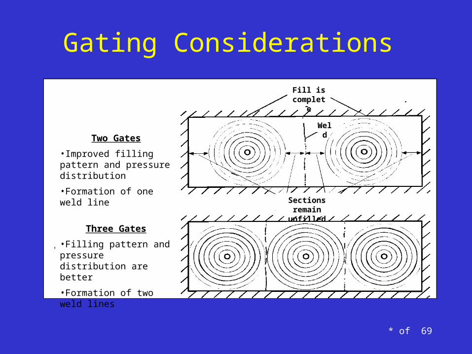
Two Gates
•Improved filling pattern and pressure distribution
•Formation of one weld line
Three Gates
•Filling pattern and pressure distribution are better
•Formation of two weld lines
Fill is complete
Sections remain unfilled
Weld
* of 69
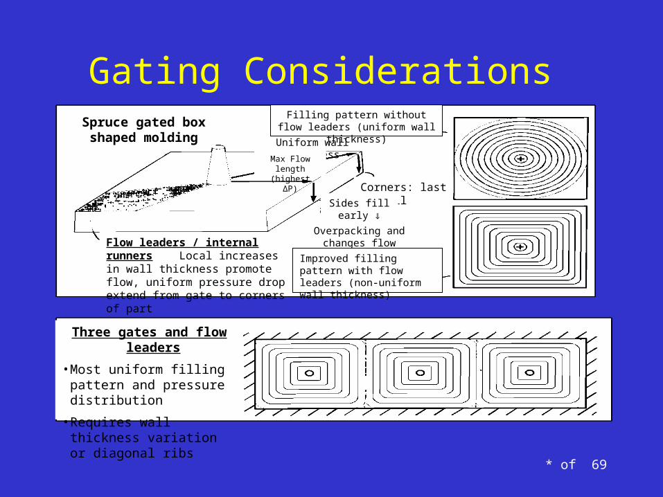
Gating Considerations
Three gates and flow leaders
• Most uniform filling pattern and pressure distribution
• Requires wall thickness variation or diagonal ribs
Spruce gated box shaped molding Uniform wall thickness
Corners: last to fill
Flow leaders / internal runners Local increases in wall thickness promote flow, uniform pressure drop extend from gate to corners of part
Filling pattern without flow leaders (uniform wall thickness)
Max Flow length (highest ΔP)
Overpacking and changes flow direction
Improved filling pattern with flow leaders (non-uniform wall thickness)
Sides fill early ⇓
Gating Considerations
• Gating system design is crucial in controlling the rate and turbulence in the molten metal being poured, the flow of liquid metal through the casting's system, and the temperature gradient within the metal casting. – good gating system will create directional solidification
throughout the casting, since the flow of molten material and temperature gradient will determine how the casting solidifies.
Source: http://thelibraryofmanufacturing.com/metalcasting_troubleshooting.html

Gating Considerations
• Superheat (The difference between the solidification temperature and the pouring temperature of the metal is called the superheat.)
– increases fluidity of the material for the casting– increases gas porosity, increased oxide formation, and
mold penetration.

Gating Considerations
• Insulate Risers– Since the riser is the reservoir of molten material for
the casting it should be last to solidify. – Insulating the top will greatly reduce cooling in the
risers from the steep temperature gradient between the liquid metal of the casting, and the room temperature air.

Gating Considerations
• Sections of the Casting– The flow of material is very important to the
manufacturing process. Do not feed a heavy section through a lighter one.
Gating Considerations
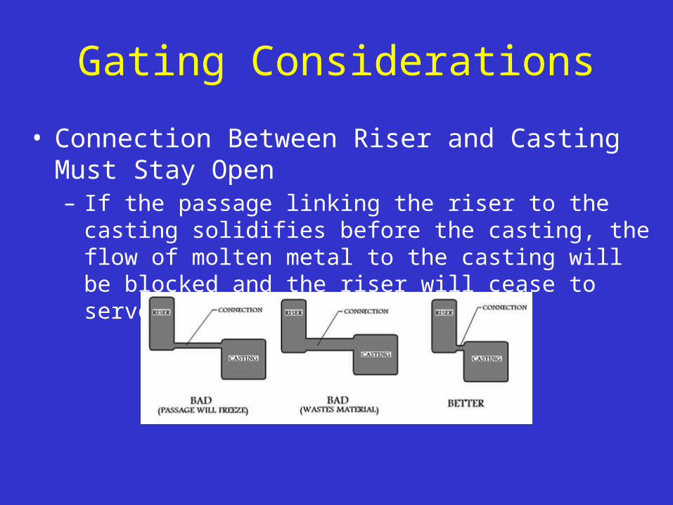
• Connection Between Riser and Casting Must Stay Open– If the passage linking the riser to the casting solidifies before
the casting, the flow of molten metal to the casting will be blocked and the riser will cease to serve its function.

Die Casting vs Other Processes• Die casting vs. plastic molding - Die casting produces stronger parts
with closer tolerances that have greater stability and durability. Die cast parts have greater resistance to temperature extremes and superior electrical properties.
• Die casting vs. sand casting - Die casting produces parts with thinner walls, closer dimensional limits and smoother surfaces. Production is faster and labor costs per casting as well as finishing costs are lower.
• Die casting vs forging - Die casting produces more complex shapes with closer tolerances, thinner walls and lower finishing costs. Cast coring holes are not available with forging.
• Die casting vs. stamping - Die casting produces complex shapes with variations possible in section thickness. One casting may replace several stampings, resulting in reduced assembly time.
Source: http://www.diecasting.org

* of 69
Lecture Topics
• Basic Casting Design Guidelines• Injection Molding Process• Gating Considerations• Case Study – Corvette Brake Pedal• Case Study – M1 Abrams Tank

* of 69
A Design Study in Aluminum Casting
The Brake Pedal for the Chevrolet Corvette
Casting\Corvette Case Study.pdf

* of 69
Lecture Topics
• Basic Casting Design Guidelines• Injection Molding Process• Gating Considerations• Case Study – Corvette Brake Pedal• Case Study – M1 Abrams Tank
* of 69
A Design Study in Steel Casting
The Ice Cleat for the M1 Abrams Tank
Casting\ice_cleat M1 Abrams.pdf

* of 69
References
• The case studies were obtained from the Engineered Casting Solutions website.– URL: http://www.castsolutions.com/
• Modern Casting, May 2001 v91 i5 p50., “Basics of Gray Iron Casting Design: 10 Rules for Engineered Quality”