英文 NICE2000 2.10 mm - szmctc.com Escalator... · NICE2000 User Manual Foreword I Foreword...
131
NICE2000 User Manual Foreword I Foreword NICE2000 is a modularized and high-powered elevator integrative controller, which is developed independently by Suzhou Monarch control technology Co., Ltd. It represents the future development trend and can satisfy the variety needs of different factories. Compared with the traditional general-type controller, it has compact structure, more convenient installation method. What is prior, its advanced motor control arithmetic, motor parameter auto-tuning (static tune and complete tune), run contactor control, brake contactor control, bypass variable frequency energy saved control, complete variable frequency energy saved control, speed track control are incomparable. Particular functions like run contactor contact detection, brake contactor contact detection, touch conglutination detection, up and down light- electricity signal, left and right armrest signal, step loss detection provide the most dependable guarantee for the safe movement of the elevator. Moreover , the special single-key design of NICE2000 elevator control system makes the complicated keyboard operation much more easier; it can use the general terminal RJ45 to connect to any position of the operation panel, that enables the adjust of the elevator convenient and simple. Main features: z Integration & Perfect combination of drive and control NICE2000 elevator control system, gathering all functions of motor driving part and control logic part in the whole, highly integrates the elevator control system, which come to a compact structure, and avoid the tedious process of choosing the logic control part and drive part respectively. It accomplishes the difficult task with much lower cost and better match which originally can only achieved by two divided parts. NICE2000 not only reduces periphery connection to a large extent, but also reinforces the safety and the stability of the elevator. & Dispense with PLC and elevator control board NICE2000 control system, integrates the motor control and elevator control, replaces the traditional PLC or the “elevator control board + inverter” control mode. It save the PLC or elevator control board so that save the electric costs, on the basis of the reliability improvement of control system. & Adapt to global variable standards
Transcript of 英文 NICE2000 2.10 mm - szmctc.com Escalator... · NICE2000 User Manual Foreword I Foreword...
NICE2000 User Manual Foreword
I
Foreword NICE2000 is a modularized and high-powered elevator integrative controller, which is developed independently by Suzhou Monarch control technology Co., Ltd. It represents the future development trend and can satisfy the variety needs of different factories. Compared with the traditional general-type controller, it has compact structure, more convenient installation method. What is prior, its advanced motor control arithmetic, motor parameter auto-tuning (static tune and complete tune), run contactor control, brake contactor control, bypass variable frequency energy saved control, complete variable frequency energy saved control, speed track control are incomparable. Particular functions like run contactor contact detection, brake contactor contact detection, touch conglutination detection, up and down light- electricity signal, left and right armrest signal, step loss detection provide the most dependable guarantee for the safe movement of the elevator.
Moreover , the special single-key design of NICE2000 elevator control system makes the complicated keyboard operation much more easier; it can use the general terminal RJ45 to connect to any position of the operation panel, that enables the adjust of the elevator convenient and simple.
Main features:
Integration
Perfect combination of drive and control
NICE2000 elevator control system, gathering all functions of motor driving part and control logic part in the whole, highly integrates the elevator control system, which come to a compact structure, and avoid the tedious process of choosing the logic control part and drive part respectively. It accomplishes the difficult task with much lower cost and better match which originally can only achieved by two divided parts. NICE2000 not only reduces periphery connection to a large extent, but also reinforces the safety and the stability of the elevator.
Dispense with PLC and elevator control board
NICE2000 control system, integrates the motor control and elevator control, replaces the traditional PLC or the “elevator control board + inverter” control mode. It save the PLC or elevator control board so that save the electric costs, on the basis of the reliability improvement of control system.
Adapt to global variable standards
Foreword NICE2000 User Manual
II
With many years professional experience in elevator control system, NICE2000 has considered the different standards in different countries. It meets the requirement of EN115 (Europe standard), AS1735 (Aussie standard), A17.1 (America standard), PUBEE (Russia standard), K (Korea standard), Hongkong and Singapore’s special requirements.
Bypass invert frequency
Dispense with braking resistance
NICE2000 elevator control system has original bypass variable frequency of the integrated control technology, taking full advantage of operation, and making conversion elevator control operate without braking resistance.
Invert frequency work frequency redundancy design
NICE2000 elevator control system has complete variable frequency control, bypass variable frequency control, Y- control etc. multi -control modes, and inside placed abundant elevator control function, and utmost satisfy the usage need of different customers, reduce fault stop rate, also provide more flexible choice to customer.
Energy saving usage
When the elevator is in the state of standby and speedup, it uses frequency-conversion control; while in stable operation, it adopts frequency control. This kind of intermittent working can surely save energy.
Professional quality
Specialized manufacture platform
The manufacturing platform of the NICE2000 adopts specialized streamline. It adopts the standardized work specification, perfect management system, advanced control and strict product examination system in the production line.
Independent wind channel design three defend processing
The internal PCBs of NICE2000 all introduce three-defend painting craft, and the whole series adopt the independent wind channel design, raising the stability of NICE2000 circulate over long-term in the elevator, automatic sidewalk in different application circumstance
Meet EMC standard
It has advanced lightning-proof design inside, which raises the credibility of the

NICE2000 User Manual Foreword
III
system consumedly. Moreover, NICE2000 elevator control system has super strong anti-interference ability, meet the harsh EMC standard.
Please read this manual carefully before you use the NICE2000 elevator control system.
The contents of the manual has already confirm before sending to press. But our company is making every effort to the continuously perfection and improvement of the production, so we the reserve the rights of modifying product specification, function and other contents of this manual. If there is any change, we won’t give prior notice.
Suzhou Monarch Control Technology Co., Ltd provides all-directions technical support for the customers. If there is any question, please contact with Monarch product sale center or the customer service center.
Thank you for your consistent support to us!
Foreword NICE2000 User Manual
IV
NICE2000 User Manual Foreword
V
Contents
Foreword........................................................................................... I Chapter 1 Safety and Precautions ............................................. - 2 - 1.1 Safety information ................................................................... - 2 -
1.2 Cautions .................................................................................. - 5 - Chapter 2 Product Information................................................. - 10 - 2.1 Name designation rules ...................................................... - 10 -
2.2 Nameplate .......................................................................... - 10 -
2.3 Controller models................................................................ - 11 -
2.4 Technical Specification........................................................ - 11 -
2.5 Product appearance and installation holes dimension........ - 12 -
2.6 option units ......................................................................... - 14 -
2 .7 Daily maintenance of controller.......................................... - 15 - Chapter 3 Installation and Wiring............................................. - 18 - 3.1 Mechanical installation........................................................ - 18 -
3.2 Electric part installation. ...................................................... - 20 -
3.3 The solution for EMC problem ............................................ - 30 - Chapter 4 Operation and Test-run of controller...................... - 34 - 4.1 technical terms of NICE2000 controller............................... - 34 -
4.2 Introduction of operation and display panel ........................ - 35 -
4.3 Function code examine & operation instruction .................. - 36 -
4.4 Operation mode of shortcut menu ...................................... - 38 -
4.5 Password setting ................................................................ - 40 - Chapter 5 Function parameter Table ....................................... - 44 - 5.1 Instruction of function parameters....................................... - 44 -
5.2 Function parameter table .................................................... - 44 - Chapter 6 Instruction of function parameter........................... - 64 - 6.1 F0 Group Basic parameter ............................................. - 64 -
6.2 F1 Group Motor parameter............................................. - 66 -
6.3 F2 Group Vector control parameter .................................. - 67 -
6.4 F3 Group Motor control parameter ................................. - 69 -
Foreword NICE2000 User Manual
VI
6.5 F4 Group Input function parameter .................................. - 71 -
6.6 F5 Group Output function parameter.............................. - 78 -
6.7 F6 Group Elevator basic parameters................................ - 81 -
6.8 F7 Group Assistant function parameter............................ - 84 -
6.9 F9 Group Assitant management parameter.................... - 88 -
6.10 F9 Group Protection function parameter ........................ - 89 -
6.11 FA Group Communication parameter ........................... - 93 -
6.12 FB Group Elevator special function setting................... - 94 -
6.13 FC group Additional function parameters........................ - 102 -
6.14 FF Group Factory parameter (reserved)..................... - 104 -
6.15 FP Group User parameter .......................................... - 104 - Chapter 7 Typical application and adjusting of system....... - 108 - 7.1 Typical application of bypass variable frequency .............. - 108 -
7.2 Typical application of complete variable frequency........... - 112 -
7.3 Adjusting procedures ........................................................ - 114 - Chapter 8 Fault Diagnosis and Countermeasures ............... - 120 - 8.1 Fault information and solutions ......................................... - 120 -
8.2 Common faults and disposal............................................. - 124 -
NICE2000 User Manual Foreword
‐ 1 ‐
Safety and Precautions
Safety and Precautions NICE2000 User Manual
‐ 2 ‐
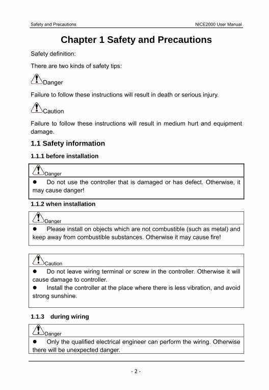
Chapter 1 Safety and Precautions Safety definition:
There are two kinds of safety tips:
Danger
Failure to follow these instructions will result in death or serious injury.
Caution
Failure to follow these instructions will result in medium hurt and equipment damage.
1.1 Safety information 1.1.1 before installation
Danger Do not use the controller that is damaged or has defect. Otherwise, it
may cause danger!
1.1.2 when installation
Danger Please install on objects which are not combustible (such as metal) and
keep away from combustible substances. Otherwise it may cause fire!
Caution Do not leave wiring terminal or screw in the controller. Otherwise it will
cause damage to controller. Install the controller at the place where there is less vibration, and avoid
strong sunshine.
1.1.3 during wiring
Danger Only the qualified electrical engineer can perform the wiring. Otherwise
there will be unexpected danger.

NICE2000 User Manual Safety and Precautions
‐ 3 ‐
Danger A circuit breaker must be installed between the electric power and the
controller. Otherwise there will be danger of fire. Wiring can only be done after the electric power is cut off. Otherwise
there will be danger of electric shock. Please connect the controller to the ground according to the standard.
Otherwise it may cause an electric shock. Do not connect the input terminals with the output terminals (U, V, W).
Otherwise the controller may be damaged. Ensure the wiring meet the EMC requirements and the slow safety
standard. Please refer to the as to the wire size. Otherwise accident may occur!
1.1.4 Before power-on
Caution Please confirm the mains voltage level is consistent with that of the
controller and the input (R, S, T) and output (U, V, W) wiring are correct, and check if there is any short circuit in peripheral circuit and if the wiring is fixed firmly. Otherwise the controller may be damaged!
Every part of the controller had passed the dielectric strength test at factory. Please do not do this test again by yourself. Otherwise accident may occur!
Danger Please mount the cover plate properly before power-on the controller.
Otherwise accident may occur! All of the wiring should comply with the instructions of the manual and
make sure connect the circuitry correctly. Otherwise accident may occur!
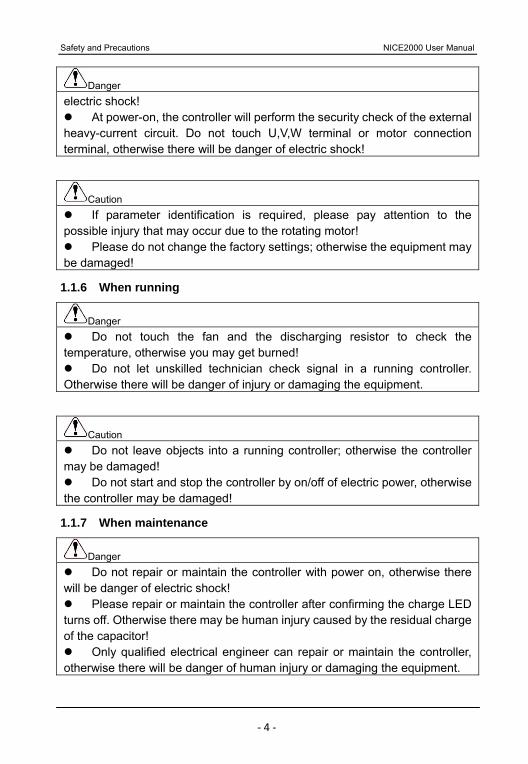
1.1.5 After power-on
Danger Do not open the cover of the controller after power-on. Otherwise there
will be danger of electric shock! Do not touch the controller and its circuit with wet hands. Otherwise
there will be danger of electric shock! Do not touch the controller terminals. Otherwise there will be danger of
Safety and Precautions NICE2000 User Manual
‐ 4 ‐
Danger electric shock!
At power-on, the controller will perform the security check of the external heavy-current circuit. Do not touch U,V,W terminal or motor connection terminal, otherwise there will be danger of electric shock!
Caution If parameter identification is required, please pay attention to the
possible injury that may occur due to the rotating motor! Please do not change the factory settings; otherwise the equipment may
be damaged!
1.1.6 When running
Danger Do not touch the fan and the discharging resistor to check the
temperature, otherwise you may get burned! Do not let unskilled technician check signal in a running controller.
Otherwise there will be danger of injury or damaging the equipment.
Caution Do not leave objects into a running controller; otherwise the controller
may be damaged! Do not start and stop the controller by on/off of electric power, otherwise
the controller may be damaged!
1.1.7 When maintenance
Danger Do not repair or maintain the controller with power on, otherwise there
will be danger of electric shock! Please repair or maintain the controller after confirming the charge LED
turns off. Otherwise there may be human injury caused by the residual charge of the capacitor!
Only qualified electrical engineer can repair or maintain the controller, otherwise there will be danger of human injury or damaging the equipment.

NICE2000 User Manual Safety and Precautions
‐ 5 ‐
1.2 Cautions 1.2.1 Check the insulation of the motor
When the motor is used for the first time, or reused after storing for a long time, or in regular checkup, the user must check the insulation of the motor to prevent the poor insulation of the windings of motor from damaging the controller. The motor connection must be divided from the controller during the insulation check. It is recommended to use a 500V Mega-Ohm-Meter to check and the insulation resistance shall not be less than 5MΩ.
1.2.2 Thermal protection of motor
If the rated capacity of the motor selected is not matching that of the controller, especially when the rated power of the controller is bigger than that of the motor, make sure to adjust the parameters for motor protection inside the controller or to install a thermal relay to the motor to guarantee the protection to the motor.
1.2.3 Run above work frequency
Please don’t use it above work frequency. If user sets the frequency above 50Hz running, please take the equipment intensity and duration into your account.
1.2.4 Motor heat and noise
Since the output voltage of the controller is in PWM wave with some harmonics, the temperature may raise, the noise and vibration may slightly increase compared with the controller running at main frequency.
1.2.5 Pressure-sensitive device or capacitor at output side
Since the controller outputs PWM wave, the capacitor (used for improving power) and pressure-sensitive resistor (used for lightening-proof) shouldn’t be installed at the output side of the controller, otherwise the controller may have transient over-current and may be damaged.
1.2.6 Switches Used at the Input and Output terminal of the Controller
If the contactor is required to be installed between the controller and the power supply, it is prohibited to start or stop the controller with this contactor. Frequent charge and discharge will shorten the life of capacitor in the controller. If the switches (such as contactors) are connected between the output terminal and the motor, make sure to start and stop the controller when the controller
Safety and Precautions NICE2000 User Manual
‐ 6 ‐
has no output, otherwise the modules in the controller may be damaged.
1.2.7 Usage beyond the range of rated voltage
NICE2000 controller shall not be used out of the specified range of operation voltage. Otherwise the internal components of the controller may be damaged. If needed, please use corresponding voltage regulation device to change the voltage.
1.2.8 Change three-phase input to two-phase input
Do not change NICE2000 control system three phase to two phase. Otherwise there will be malfunction or controller damaged.
1.2.9 Lightning proof
There are lightning-proof devices inside the controller and can protect itself from some inductive thunders, but the user should install other lightning protection device at the front of the controller if lightning strike occurs frequently.
1.2.10 Altitude and de-rating use
When the altitude is higher than 1000m, the cooling effect is deteriorated because of the rarefaction of air; the de-rating method must be used. Please refer to our company for detailed technical support.
1.2.11 Some special usages
If customer needs to use other wiring methods beyond the graphs in the manual, please contact our company..
1.2.12 Disposal of controller
The electrolytic capacitors in the main circuits and PCB may explode when they are burned and poisonous gas may be generated when the plastic parts are burned. Please dispose the controller as industrial rubbish.
1.2.13 About adapt motor
The standardized applicable motor of controller is four-pole squirrel-cage asynchronous motor. Please pay attention to the useable range of the controller rated current when select the applicable motor.
The cooling fan and rotor axis of the un-conversion motor is linked in the same axis. When the rotor speed slows down, the fan cooling effect will be

NICE2000 User Manual Safety and Precautions
‐ 7 ‐
reduced too. Therefore, customer should add strong exhaust fan or replace the motor into variable frequency motor in the circumstance of motor overheat.
Short circuit inside the cable or motor will result in the controller alarm, even exploded the motor. Please do the insulating-short-circuit test at beginning. This test is also necessary in the daily maintenance. When doing this test, the controller and tested part must be cut off completely.
Safety and Precautions NICE2000 User Manual
‐ 8 ‐
NICE2000 User Manual Safety and Precautions
‐ 9 ‐
Product Information
Product Information NICE2000 User Manual
‐ 10 ‐
Chapter 2 Product Information Summarize:
In this chapter we introduce NICE2000 elevator control system in details, including related information of each part, daily usage and maintenance, type selection instruction of it and so on. It will help the clients to use our products safely.
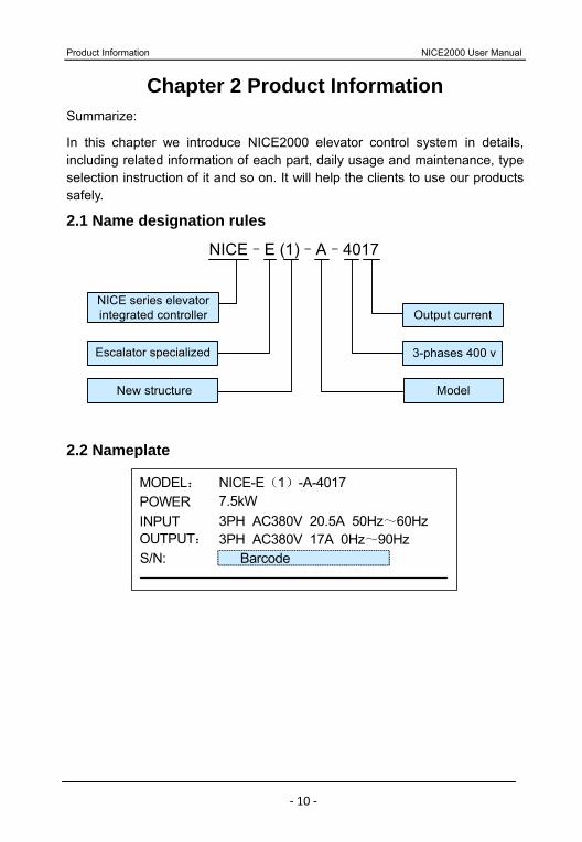
2.1 Name designation rules
NICE series elevator integrated controller
Escalator specialized
Model
NICE–E (1)–A–4017
Output current
3-phases 400 v
New structure
2.2 Nameplate
MODEL: POWER
OUTPUT: S/N: Barcode
NICE-E(1)-A-40177.5kW
3PH AC380V 17A 0Hz~90Hz INPUT 3PH AC380V 20.5A 50Hz~60Hz
NICE2000 User Manual Product Information
‐ 11 ‐
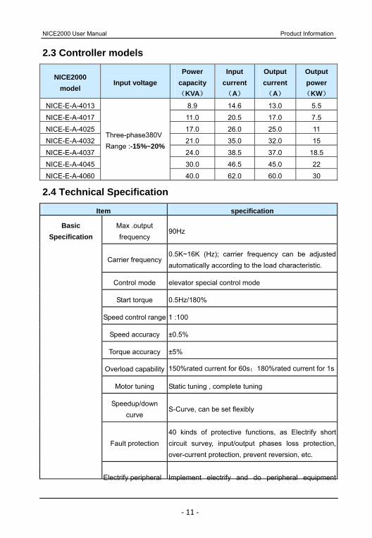
2.3 Controller models
NICE2000 model
Input voltage Power
capacity (KVA)
Input current(A)
Output current (A)
Output power (KW)
NICE-E-A-4013 8.9 14.6 13.0 5.5
NICE-E-A-4017 11.0 20.5 17.0 7.5
NICE-E-A-4025 17.0 26.0 25.0 11
NICE-E-A-4032 21.0 35.0 32.0 15
NICE-E-A-4037 24.0 38.5 37.0 18.5
NICE-E-A-4045 30.0 46.5 45.0 22
NICE-E-A-4060
Three-phase380VRange :-15%~20%
40.0 62.0 60.0 30
2.4 Technical Specification
Item specification
Max .output frequency
90Hz
Carrier frequency0.5K~16K (Hz); carrier frequency can be adjusted automatically according to the load characteristic.
Control mode elevator special control mode
Start torque 0.5Hz/180%
Speed control range 1 :100
Speed accuracy ±0.5%
Torque accuracy ±5%
Overload capability 150%rated current for 60s;180%rated current for 1s
Motor tuning Static tuning , complete tuning
Speedup/down curve
S-Curve, can be set flexibly
Fault protection 40 kinds of protective functions, as Electrify short circuit survey, input/output phases loss protection, over-current protection, prevent reversion, etc.
Basic Specification
Electrify peripheral Implement electrify and do peripheral equipment

Product Information NICE2000 User Manual
‐ 12 ‐
Item specification
equipment safety auto-check
detection like grounding、short circuit etc.
State monitor Judge the work state according to feedback signals toensure the escalator work effectively.
Switch input 19 switch input terminal, input specification:24V, 5mA
Switch output 12 relay output, with corresponding function setup neatly I / O interface
Analogue 2 analogue input terminals, 1 analogue output terminal
Operation panel5-bit LED display, with operating speed and bus voltage parameters. Display and
keypad Computer monitor Monitor the parameters in all states
Altitude Lower than 1000m
Ambient temperature
-10 ~+ 40 ( ambient temperature is within40 ~ 50 duration is required)
Humidity Less than 95%RH, without condensation
Vibration Less than 5.9m/s2(0.6g)
Application environment
Storage temperature
-20~+60
2.5 Product appearance and installation holes dimension 2.5.1 Serial Product appearance
NICE2000 User Manual Product Information
‐ 13 ‐
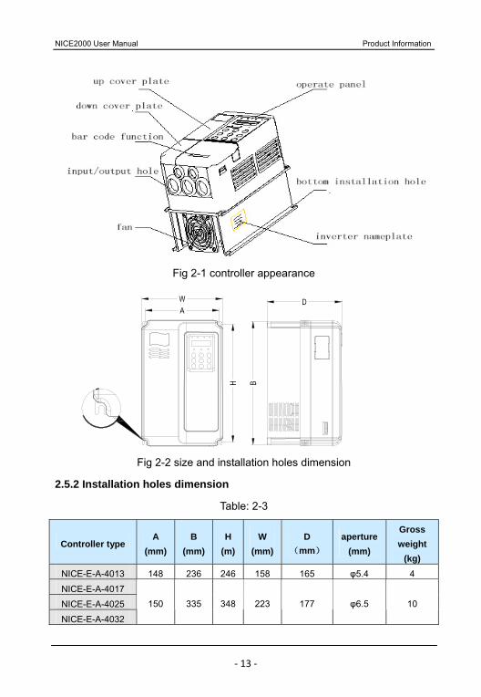
Fig 2-1 controller appearance
Fig 2-2 size and installation holes dimension
2.5.2 Installation holes dimension
Table: 2-3
Controller type A
(mm)B
(mm)H
(m)W
(mm)D
(mm)
aperture(mm)
Gross weight
(kg) NICE-E-A-4013 148 236 246 158 165 φ5.4 4
NICE-E-A-4017
NICE-E-A-4025
NICE-E-A-4032
150 335 348 223 177 φ6.5 10
Product Information NICE2000 User Manual
‐ 14 ‐
Controller type A
(mm)B
(mm)H
(m)W
(mm)D
(mm)
aperture(mm)
Gross weight
(kg) NICE-E-A-4037
NICE-E-A-4045
NICE-E-A-4060
235 447 460 285 220 φ6.5 14
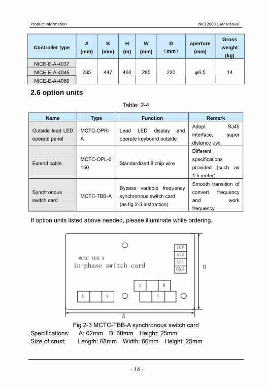
2.6 option units
Table: 2-4
Name Type Function Remark
Outside lead LED operate panel
MCTC-OPR-A
Lead LED display and operate keyboard outside
Adopt RJ45 interface, super distance use
Extend cable MCTC-OPL-0150
Standardized 8 chip wire
Different specifications provided (such as 1.5 meter)
Synchronous switch card
MCTC-TBB-ABypass variable frequency synchronous switch card (as fig 2-3 instruction)
Smooth transition of convert frequency and work frequency
If option units listed above needed, please illuminate while ordering.
Fig 2-3 MCTC-TBB-A synchronous switch card
Specifications: A: 62mm B: 60mm Height: 25mm Size of crust: Length: 68mm Width: 66mm Height: 25mm
NICE2000 User Manual Product Information
‐ 15 ‐
2 .7 Daily maintenance of controller 2.7.1 Daily maintenance
The components in the controller may become aging due to the influence of ambient temperature, humidity, dust and vibration, which will cause further potential faults and reduce the life of controller. Therefore, it is necessary to keep daily or periodic maintenance of controller.
Danger
Never do maintenance or repair work to the controller, since there still exist high voltage at filter capacitor after the power supply is switched off in a short time. Wait until the light “CHARGR” off, and the bus-voltage is lower than 36V.
1) Daily check items:
Check if there is any abnormal noise during the running of the motor;
Check if there is strong vibration of motor;
Check if the installation environment of controller changes;
Check if the cooling fan of controller works normally;
Check if the controller is over heated.
2) Daily cleaning
Always keep the controller in a clean state. Clean the dust on the controller and prevent the dust especially the metal
powder; Clean the oil dirt in the cooling fan of the controller.
2.7.2 Periodical maintenance
It focuses on the places that can be hardly checked during the daily check.
1) Periodical maintenance items:
Check the air channels and clean them periodically. Check whether the screws are loose. Check whether the controller is rusted. Check whether the input / output terminals have scratch or pulling trace. Insulation test in main circuit.
Product Information NICE2000 User Manual
‐ 16 ‐
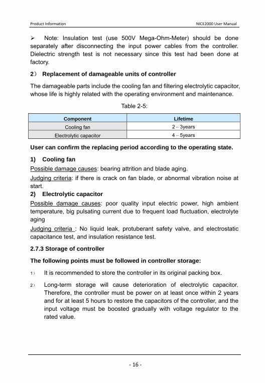
Note: Insulation test (use 500V Mega-Ohm-Meter) should be done separately after disconnecting the input power cables from the controller. Dielectric strength test is not necessary since this test had been done at factory.
2) Replacement of damageable units of controller
The damageable parts include the cooling fan and filtering electrolytic capacitor, whose life is highly related with the operating environment and maintenance.
Table 2-5:
Component Lifetime Cooling fan 2~3years
Electrolytic capacitor 4~5years
User can confirm the replacing period according to the operating state.
1) Cooling fan Possible damage causes: bearing attrition and blade aging. Judging criteria: if there is crack on fan blade, or abnormal vibration noise at start. 2) Electrolytic capacitor Possible damage causes: poor quality input electric power, high ambient temperature, big pulsating current due to frequent load fluctuation, electrolyte aging Judging criteria : No liquid leak, protuberant safety valve, and electrostatic capacitance test, and insulation resistance test.
2.7.3 Storage of controller
The following points must be followed in controller storage:
1) It is recommended to store the controller in its original packing box.
2) Long-term storage will cause deterioration of electrolytic capacitor. Therefore, the controller must be power on at least once within 2 years and for at least 5 hours to restore the capacitors of the controller, and the input voltage must be boosted gradually with voltage regulator to the rated value.

Product Information NICE2000 User Manual
17
Installation and Wiring
Installation and Wiring NICE2000 User Manual
‐ 18 ‐
Chapter 3 Installation and Wiring Do open the packing and check the controller before installation. Please confirm these information listed below carefully: 1) Check that if the model and the rated power is complied with your order.
Your ordered machine, product certification, user manual and warranty card will be in the package.
2) Check if the machine is broken during the transportation; if there is any miss or damage, please contact with our company or agent as soon as possible.
Note: Installation and wiring should strictly comply with the criterions in chapter 1.
3.1 Mechanical installation
1) Installation environment
a) Temperature: The ambient temperature will bring great affect to the life of controller. The allowable extent is -10 ~+50 .
b) Mount the controller on incombustible surface (such as metal) with enough space to spread heat. And use screw to mount it vertically on the bracket.
c) Mount the controller at places with less than 0.6G vibration. Never near punch and kindred equipment.
d) Avoid places with direct sunshine or dampness. e) Avoid place with corrosive, flammable, explosive gas f) Avoid places with oil dirt, dust or metal powder.
2) Installation position

NICE2000 User Manual Installation and Wiring
‐ 19 ‐
Fig 3-1 installation position
Instruction:
When the controller power is less than 22kw, the size of A can be left out of account; and when the controller power is more than 22kw, A shall be bigger than 50mm.
Heat dissipation is a big issue, so pay attention to the notices below: 1) Please install the controller vertically to be convenient for heat dispelling upwards. Never invert. 2) The installation space should be absolutely conforming to Fig 3-1 to make sure the heat dissipation of the machine. And do not forget the heat situation of other parts in the cabinet. 3) Installation bracket should be incombustible material. 4) As to the hermetic places with powder, the space should be enough.
3) Teardown and installation of panel
NICE2000 controller (under 15KW) adopts plastic shell, the teardown and installation information is in Fig 3-2. 1) Teardown: Find the pothooks under the plate, and push towards inside, using tools. 2) Installation: First, put the upside meatus (at the down cover plate) into the apertures (at the up cover plate), then press forcibly downwards until hearing the sound of “chatter”.
Note: Don’t teardown the main part of the plastic shell. please contact our company if repairing needed.
Installation and Wiring NICE2000 User Manual
‐ 20 ‐
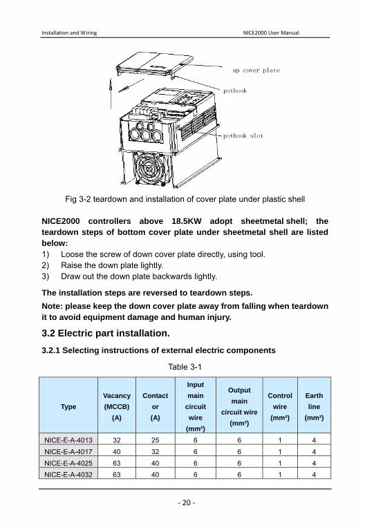
Fig 3-2 teardown and installation of cover plate under plastic shell
NICE2000 controllers above 18.5KW adopt sheetmetal shell; the teardown steps of bottom cover plate under sheetmetal shell are listed below: 1) Loose the screw of down cover plate directly, using tool. 2) Raise the down plate lightly. 3) Draw out the down plate backwards lightly.
The installation steps are reversed to teardown steps. Note: please keep the down cover plate away from falling when teardown it to avoid equipment damage and human injury.
3.2 Electric part installation. 3.2.1 Selecting instructions of external electric components
Table 3-1
Type Vacancy(MCCB)
(A)
Contactor (A)
Input main
circuit wire
(mm²)
Output main
circuit wire (mm²)
Control wire
(mm²)
Earth line
(mm²)
NICE-E-A-4013 32 25 6 6 1 4
NICE-E-A-4017 40 32 6 6 1 4
NICE-E-A-4025 63 40 6 6 1 4
NICE-E-A-4032 63 40 6 6 1 4
NICE2000 User Manual Installation and Wiring
‐ 21 ‐
Type Vacancy(MCCB)
(A)
Contactor (A)
Input main
circuit wire
(mm²)
Output main
circuit wire (mm²)
Control wire
(mm²)
Earth line
(mm²)
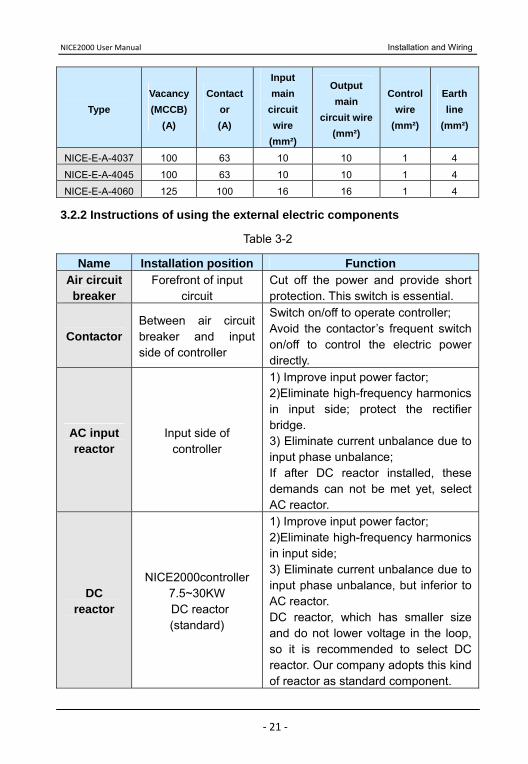
NICE-E-A-4037 100 63 10 10 1 4
NICE-E-A-4045 100 63 10 10 1 4
NICE-E-A-4060 125 100 16 16 1 4
3.2.2 Instructions of using the external electric components
Table 3-2
Name Installation position Function Air circuit breaker
Forefront of input circuit
Cut off the power and provide short protection. This switch is essential.
Contactor Between air circuit breaker and input side of controller
Switch on/off to operate controller; Avoid the contactor’s frequent switch on/off to control the electric power directly.
AC input reactor
Input side of controller
1) Improve input power factor; 2)Eliminate high-frequency harmonics in input side; protect the rectifier bridge. 3) Eliminate current unbalance due to input phase unbalance; If after DC reactor installed, these demands can not be met yet, select AC reactor.
DC reactor
NICE2000controller 7.5~30KW
DC reactor (standard)
1) Improve input power factor; 2)Eliminate high-frequency harmonics in input side; 3) Eliminate current unbalance due to input phase unbalance, but inferior to AC reactor. DC reactor, which has smaller size and do not lower voltage in the loop, so it is recommended to select DC reactor. Our company adopts this kind of reactor as standard component.
Installation and Wiring NICE2000 User Manual
‐ 22 ‐
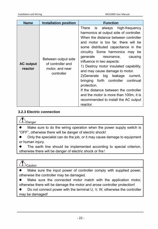
Name Installation position Function
AC output reactor
Between output side of controller and motor, and near
controller
There is always high-frequency harmonics at output side of controller. When the distance between controller and motor is too far, there will be some distributed capacitance in the circuitry. Some harmonics may be generate resonance, causing influence in two aspects: 1) Destroy motor insulated capability, and may cause damage to motor. 2)Generate big leakage current, bringing forth controller continual protection. If the distance between the controller and the motor is more than 100m, it is recommended to install the AC output reactor.
3.2.3 Electric connection
Danger Make sure to do the wiring operation when the power supply switch is
“OFF”, otherwise there will be danger of electric shock! Only the specialist can do the job, or it may cause damage to equipment
or human injury. The earth line should be implemented according to special criterion,
otherwise there will be danger of electric shock or fire!
Caution Make sure the input power of controller comply with supplied power,
otherwise the controller may be damaged. Make sure the connected motor match with the application motor,
otherwise there will be damage the motor and arose controller protection! Do not connect power with the terminal U, V, W, otherwise the controller
may be damaged!
NICE2000 User Manual Installation and Wiring
‐ 23 ‐
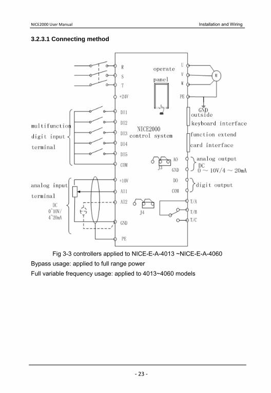
3.2.3.1 Connecting method
Fig 3-3 controllers applied to NICE-E-A-4013 ~NICE-E-A-4060
Bypass usage: applied to full range power Full variable frequency usage: applied to 4013~4060 models
Installation and Wiring NICE2000 User Manual
‐ 24 ‐
Y11
Y10
Y9
CM2
Y8
Y7
Y6
Y5
Y4
Y3
Y2
Y1
CM1
NICE2000(
extend board)
automatic energy save
high speed
bypass
X14
X13
X12
pre-reversion
up step loss
down step loss
fire alarm
brake open switch
X9
X10
X11
X8
X7
0VDC24V+
Vexamine and repair X1
safety
touch point conglutination
drive chain
down
up
X4
X5
X6
X3
X2
DC-DC+
assist brake signal relay output
down direction signal relay output
up direction signal relay output
buzzer signal relay output
oil signal relay output
up running signal relay output
brake signal relay output
run signal relay output
signal relay output
Y signal relay output
down running signal relay output
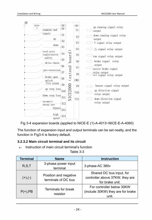
Fig 3-4 expansion boards (applied to NICE-E (1)-A-4013~NICE-E-A-4060)
The function of expansion input and output terminals can be set neatly, and the function in Fig3-4 is factory default.
3.2.3.2 Main circuit terminal and its circuit a) Instruction of main circuit terminal’s function
Table 3-3
Terminal Name Instruction
R,S,T 3-phase power input
terminal 3-phase AC 380v
(+),(-) Position and negative terminals of DC bus
Shared DC bus input, for controller above 37KW, they are
for brake unit.
P(+),PB Terminals for break
resistor
For controller below 30KW (include 30KW) they are for brake
unit.
NICE2000 User Manual Installation and Wiring
‐ 25 ‐
Terminal Name Instruction U,V,W Controller output terminal Connect 3-phase motor
PE Terminal for grounding Grounding terminal
b) Cautions in wiring a) DC bus (+) and (-) terminals:
Please pay attention that the DC bus terminals (+) and (-) still have voltage after power off, and the user cannot touch the terminals until the indicator light “CHARGE” turns off and the voltage is below 36V.
Do not connect the brake resistance with DC current bus directly; otherwise it may cause damage to controller or even fire.
b) Controller output side U,V, W
The output side of controller should connect to 3-phase motor. When the motor operating direction is reversed with the actual requirement, change any two of the U, V, W cables to change the operating direction.
The output of controller cannot connect to capacitors or inrush absorber, otherwise it may cause frequent protection of the controller or damage to it.
Controller output circuit earth line or short circuit is forbidden.
Controller output cables of U, V and W should be in metal pipe with earth line, and divided or vertical with control circuit cables.
If the cables between the motor and the controller are too long, electrical resonance may occur due to the distributed capacitance, which may result in damage to the motor insulation or leakage current that will make the controller go into protective status. Usually, the cable length should be less than 100m. It is recommended to add AC output reactor when the length is above 100m.
c) Grounding terminal
Grounding terminal must be connected to the ground reliably. The ground cable should be thick and short, and we recommend using special yellow-green cable above 4 square mm with several copper cores. And the grounding resistance shall be less than 5Ω. Do not share the GE (ground electrode) and neutral line of main supply
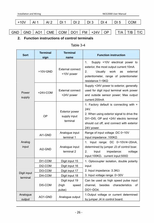
3.2.3.3 Terminal and its wiring 1. Terminal collocation in controller circuit.
Installation and Wiring NICE2000 User Manual
‐ 26 ‐
+10V AI 1 AI 2 DI 1 DI 2 DI 3 DI 4 DI 5 COM
2. Function instructions of control terminals
Table 3-4
Sort Terminal
sign Terminal
name Function instruction
+10V-GND External connect
+10V power
1. Supply +10V electrical power to exterior, the most output current:10mA 2. Usually work as external potentiometer, range of potentiometer resistance:1~5KΩ
+24V-COM External connect
+24V power
Supply +24V power to exterior, generally used for digit input terminal work power and outside sensor power; Max output current:200mA
Power supply
OP Exterior power supply input
terminal
1. Factory default is connecting with + 24V. 2. When using exterior signal to drive the DI1~DI5, OP and +24V electric terminal should cut off, and connect with exterior 24V power.
AI1-GND Analogue input
terminal 1 Range of input voltage :DC 0~10V Input impedance :100KΩ
Analog input
AI2-GND Analogue input
terminal 2
1. Input range: DC 0~10V/4~20mA, determined by jumper J3 of control boar.2. Input impedance: voltage input:100KΩ,current input:500Ω
DI1-COM Digit input 15
DI2-COM Digit input 16
DI3-COM Digit input 17
DI4-COM Digit input 18
1. Optocoupler isolation, double polarity input 2. Input impedance :3.3KΩ 3. Input voltage range :0~30V
Digit input terminal
DI5-COM Digit input 19
(high speed pulse)
Can be used as high speed pulse input channel, besides characteristics of DO1~DO4.
Analogue output
AO1-GND Analogue output1.Output voltage or current determined by jumper J4 in control board.
GND GND AO1 CME COM DO1 FM +24V OP T/A T/B T/C
NICE2000 User Manual Installation and Wiring
‐ 27 ‐
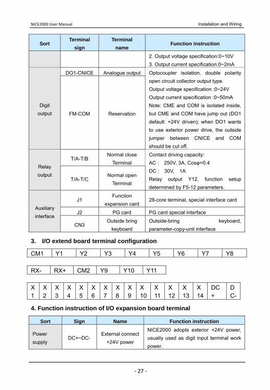
Sort Terminal
sign Terminal
name Function instruction
2. Output voltage specification:0~10V 3. Output current specification:0~2mA
DO1-CNICE Analogue output
Digit output FM-COM Reservation
Optocoupler isolation, double polarity open circuit collector output type. Output voltage specification :0~24V Output current specification :0~50mA Note: CME and COM is isolated inside, but CME and COM have jump out (DO1 default: +24V driven); when DO1 wants to use exterior power drive, the outside jumper between CNICE and COM should be cut off.
T/A-T/B Normal close
Terminal Relay output
T/A-T/C Normal open
Terminal
Contact driving capacity: AC : 250V, 3A, Cosφ=0.4 DC : 30V, 1A Relay output Y12, function setup determined by F5-12 parameters.
J1 Function
expansion card 28-core terminal, special interface card
J2 PG card PG card special interface Auxiliary interface
CN3 Outside bring
keyboard Outside-bring keyboard, parameter-copy-unit interface
3. I/O extend board terminal configuration
CM1 Y1 Y2 Y3 Y4 Y5 Y6 Y7 Y8 RX- RX+ CM2 Y9 Y10 Y11 X1
X2
X3
X4
X5
X6
X7
X8
X9
X10
X11
X12
X13
X14
DC+
DC-
4. Function instruction of I/O expansion board terminal
Sort Sign Name Function instruction
Power supply
DC+~DC- External connect
+24V power
NICE2000 adopts exterior +24V power, usually used as digit input terminal work power.
Installation and Wiring NICE2000 User Manual
‐ 28 ‐
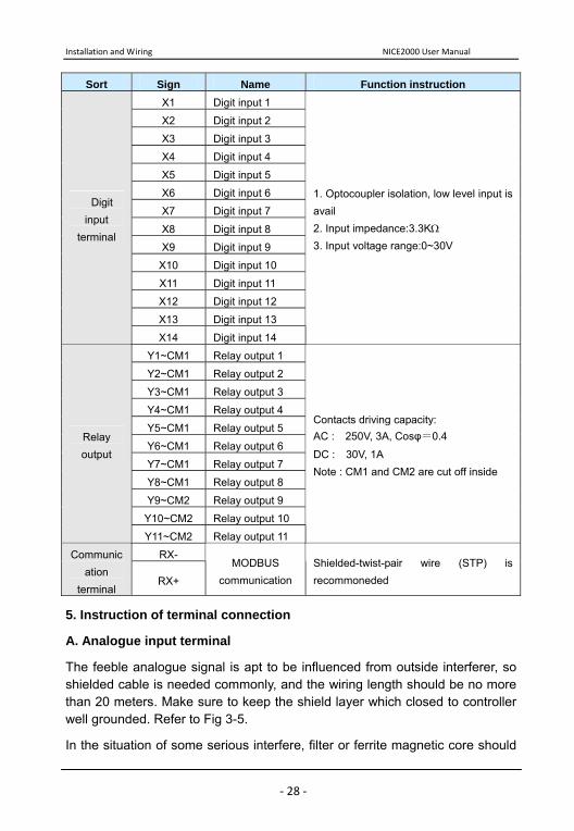
Sort Sign Name Function instruction X1 Digit input 1
X2 Digit input 2
X3 Digit input 3
X4 Digit input 4
X5 Digit input 5
X6 Digit input 6
X7 Digit input 7
X8 Digit input 8
X9 Digit input 9
X10 Digit input 10
X11 Digit input 11
X12 Digit input 12
X13 Digit input 13
Digit input
terminal
X14 Digit input 14
1. Optocoupler isolation, low level input is avail 2. Input impedance:3.3KΩ 3. Input voltage range:0~30V
Y1~CM1 Relay output 1
Y2~CM1 Relay output 2
Y3~CM1 Relay output 3
Y4~CM1 Relay output 4
Y5~CM1 Relay output 5
Y6~CM1 Relay output 6
Y7~CM1 Relay output 7
Y8~CM1 Relay output 8
Y9~CM2 Relay output 9
Y10~CM2 Relay output 10
Relay output
Y11~CM2 Relay output 11
Contacts driving capacity: AC : 250V, 3A, Cosφ=0.4
DC : 30V, 1A Note : CM1 and CM2 are cut off inside
RX- Communication
terminal RX+
MODBUS communication
Shielded-twist-pair wire (STP) is recommoneded
5. Instruction of terminal connection
A. Analogue input terminal
The feeble analogue signal is apt to be influenced from outside interferer, so shielded cable is needed commonly, and the wiring length should be no more than 20 meters. Make sure to keep the shield layer which closed to controller well grounded. Refer to Fig 3-5.
In the situation of some serious interfere, filter or ferrite magnetic core should

NICE2000 User Manual Installation and Wiring
‐ 29 ‐
be added at the side of analogue signal source. Refer to Fig 3-6.
Fig 3-5 Terminal connection Fig 3-6 Signal disposal connection
B. Digital input terminal
Shielded cable or twisted line are usually used in wiring (refer to 3.2.1 external electric components), and the wiring length must be as short as possible (less than 20 meters). If use shielded line, please connect shielded layer into terminal PE which is near the side of controller.
When using active drive, filter measure is essential to avoid serial interfere.
It is recommended to use contact control mode.
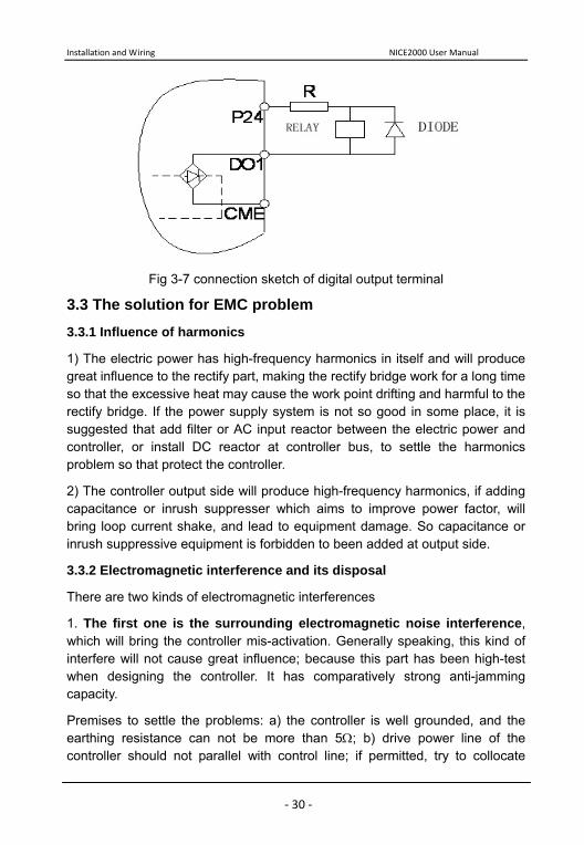
C. Digital output terminal
When digital output terminals need to drive the relay, absorbing diode should be added at both sides of relay loop. Otherwise the DC 24V power will be damaged.
Note: Absorbing diode must be setup correctly, which means its polarities have to be installed properly. Otherwise when the digital output terminal have output, it will burn out the DC 24V power immediately.
Installation and Wiring NICE2000 User Manual
‐ 30 ‐
Fig 3-7 connection sketch of digital output terminal
3.3 The solution for EMC problem 3.3.1 Influence of harmonics
1) The electric power has high-frequency harmonics in itself and will produce great influence to the rectify part, making the rectify bridge work for a long time so that the excessive heat may cause the work point drifting and harmful to the rectify bridge. If the power supply system is not so good in some place, it is suggested that add filter or AC input reactor between the electric power and controller, or install DC reactor at controller bus, to settle the harmonics problem so that protect the controller.
2) The controller output side will produce high-frequency harmonics, if adding capacitance or inrush suppresser which aims to improve power factor, will bring loop current shake, and lead to equipment damage. So capacitance or inrush suppressive equipment is forbidden to been added at output side.
3.3.2 Electromagnetic interference and its disposal
There are two kinds of electromagnetic interferences
1. The first one is the surrounding electromagnetic noise interference, which will bring the controller mis-activation. Generally speaking, this kind of interfere will not cause great influence; because this part has been high-test when designing the controller. It has comparatively strong anti-jamming capacity.
Premises to settle the problems: a) the controller is well grounded, and the earthing resistance can not be more than 5Ω; b) drive power line of the controller should not parallel with control line; if permitted, try to collocate
NICE2000 User Manual Installation and Wiring
‐ 31 ‐
vertically; c) at the place with high interfering request, shielded cable between controller and motor should be adopted and keep shielded layer well grounded. d) as to the down-lead which suffer the influence of interference, it is suggested to use double-twist shielded line, and keep the shielded layer well grounded.
There are two kinds of surrounding electromagnetic noise interferences: one is controller’s radiation, the other is produced by the down-leads between controller and motor. Both will bring electromagnetism or electrostatic induction to the surface of the surrounding equipments. Common solutions are listed below:
1) Apparatus, receivers or sensors which are used for measuring, usually have the feeble signal around. If closed to controller or in the same control panel, they are liable to get interference and come into malfunction. It is recommended to use following solutions: keep away from the interfere power; don’t make the signal line parallel to the driving line, and parallel enlacement together is especially prohibitive; the signal line and driving line should adopt shielded cable; add linear filter or wireless noise filter in the input and output side of the controller. 2) When interfered equipment and controller use the same power, the best bet is to add linear filter or wireless noise filter between the controller and power if the interference isn’t alleviative by the above solutions. 3) Earth the peripheral equipments separately, which can eliminate the interference generated by grounding line’s leakage current due to earthing together. 2. The other one is interference produced by the surrounding equipment.
The ecumenical reason is that there are large numbers of relays, contactors or electromagnetic arresters around the controller.
When facing with this kind of problem, use the following methods:
1) Add inrush suppresser in the equipment which produce interfere. 2) Add filter at the signal input terminal of the controller.
3.3.3 Electric leakage and its disposal
There are two forms of electric leakage when using controller: 1) leakage current to earth; 2) leakage among the lines.
Installation and Wiring NICE2000 User Manual
‐ 32 ‐
1) Factors influencing leakage current to earth and solution.
There are distributed capacitance between lead and earth. The more the distributed capacitance is, the larger the leakage current will be; to minish the distance between the controller and motor will reduce the distributed capacitance.
The higher the carrier frequency is, the larger the leakage current will be; we can reduce carrier frequency to reduce leakage current; but remember that it will increase the motor noise.
Adding reactor is also an efficient way to resolve the leakage current.
2) Leakage current will be increased with the increase of loop current; therefore, large motor power will lead to corresponding large leakage current.
3) Factors influencing leakage current among the lines and solution.
There exists distributed capacitance among the controller output lines; if the current passing circuitry has high-frequency harmonics, resonance will occur and then lead to leakage current. Using thermal overload relay here will cause malfunction.
The resolvent is to reduce carrier frequency or to add output reactor. It is not suggested that to add thermal overload relay in the front of motor when using the controller; use the electro-over-current protective function of the controller.
NICE2000 User Manual Installation and Wiring
‐ 33 ‐
Operation and Test-run of controller
Operation and Test-run of controller NICE2000 User Manual
‐ 34 ‐
Chapter 4 Operation and Test-run of controller Summarize: we will give detailed information in operating keyboard and function code setting of display panel of the NICE2000 in this chapter.
4.1 technical terms of NICE2000 controller
Main parts: operation mode, control mode, running mode and working state.
4.1.1 Operation mode
The definition of operation mode: it is the modes of receiving running command and speed instruction. NICE2000 control system can select only one of the operating modes hereinafter.
1) Operating panel control: use the key RUN and STOP of the operating panel to control the controller output.
2) Command control terminal: the running command and running speed are controlled by multi-functional input signal of input terminal.
4.1.2 Running mode
NICE2000 control system can select only one of the control modes hereinafter.
1) Self-tuning running mode: NICE2000 control system provides self learning mode under loaded state and unloaded state. For details, please refer to parameter F1-11.
2) Common running mode: running under the control of operating panel.
3) Elevator control mode: the running speed is controlled according to the logic state of elevator control carry through auto selection.
4.1.3 Working state
NICE2000 control system have four states in live state: stop state, program state, running state and fault-alarm state.
1) Stop state:
Re-electrify or stop after running command finished, the controller is always at the wait state until receiving another running command. At this moment, indicator light will go out, with the contents in LED screen flashing; can use key “》”to display different parameter circularly.
2) Program state:
NICE2000 User Manual Operation and Test-run of controller
‐ 35 ‐
Examine and set up the parameters through operating panel of controller.
3) Running state:
The running indicator light is on when the controller is at the state of running, with the contents in LED screen un-flashing
4) Fault alarm state:
There comes fault of controller and the fault code is displayed.
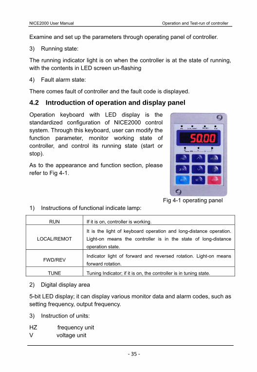
4.2 Introduction of operation and display panel
Operation keyboard with LED display is the standardized configuration of NICE2000 control system. Through this keyboard, user can modify the function parameter, monitor working state of controller, and control its running state (start or stop).
As to the appearance and function section, please refer to Fig 4-1.
1) Instructions of functional indicate lamp:
RUN If it is on, controller is working.
LOCAL/REMOT It is the light of keyboard operation and long-distance operation. Light-on means the controller is in the state of long-distance operation state.
FWD/REV Indicator light of forward and reversed rotation. Light-on means forward rotation.
TUNE Tuning Indicator; if it is on, the controller is in tuning state.
2) Digital display area
5-bit LED display; it can display various monitor data and alarm codes, such as setting frequency, output frequency.
3) Instruction of units:
HZ frequency unit V voltage unit
Fig 4-1 operating panel
Operation and Test-run of controller NICE2000 User Manual
‐ 36 ‐
% percentage A current unit RPM rotation speed unit
4) Instruction of buttons on keyboard
Table 4-1 Keyboard function
Key Name Function
PRG Program key Enter and exit the first-level menu and delete quick parameter
ENTER Confirm key Enter the menu level by level and set parameter conformation
∧ Up key Increase of data and function code
∨ Down key Decrease of data and function code
》 Shift key Select the display parameters circularly at stop state and running state. Select the modification bit when modifying parameters.
RUN Run key Start up the machine in the terms of keyboard operation mode.
STOP/RESET
Stop/Reset keyStop the machine when the controller is in running. Reset the machine, when in the state of fault alarm.
QUICK Quick key Enter or exit the first-level of quick menu. Refer to QUICK operation instruction
MF.K Multi-function selection key
Display and remove error information.
4.3 Function code examine & operation instruction 4.3.1 Operation flow of 3-level menu
NICE2000 adopts 3-level menu to conduct the parameter setting. It’s convenient to query and modify function code and parameter.
3-level menu include: function parameter group (first level)→function code (second level)→function code setting(third level). You can refer to operation flow chart Fig4-2.
NICE2000 User Manual Operation and Test-run of controller
‐ 37 ‐
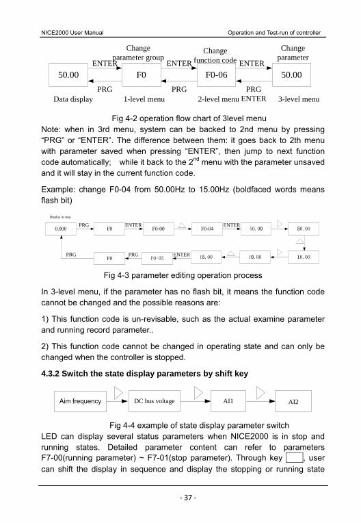
50.00 F0 F0-06 50.00PRG PRG PRG
ENTER
ENTER ENTER ENTER
Data display
Change function code
Changeparameter
Change parameter group
1-level menu 2-level menu 3-level menu
Fig 4-2 operation flow chart of 3level menu Note: when in 3rd menu, system can be backed to 2nd menu by pressing “PRG” or “ENTER”. The difference between them: it goes back to 2th menu with parameter saved when pressing “ENTER”, then jump to next function code automatically; while it back to the 2nd menu with the parameter unsaved and it will stay in the current function code.
Example: change F0-04 from 50.00Hz to 15.00Hz (boldfaced words means flash bit)
50.00F0-04F0-00ENTER ENTER
50.00
10.0010.0015.00F0-05ENTER
F0PRG
0.000 F0PRG
PRG
Display in stop
Fig 4-3 parameter editing operation process
In 3-level menu, if the parameter has no flash bit, it means the function code cannot be changed and the possible reasons are:
1) This function code is un-revisable, such as the actual examine parameter and running record parameter..
2) This function code cannot be changed in operating state and can only be changed when the controller is stopped.
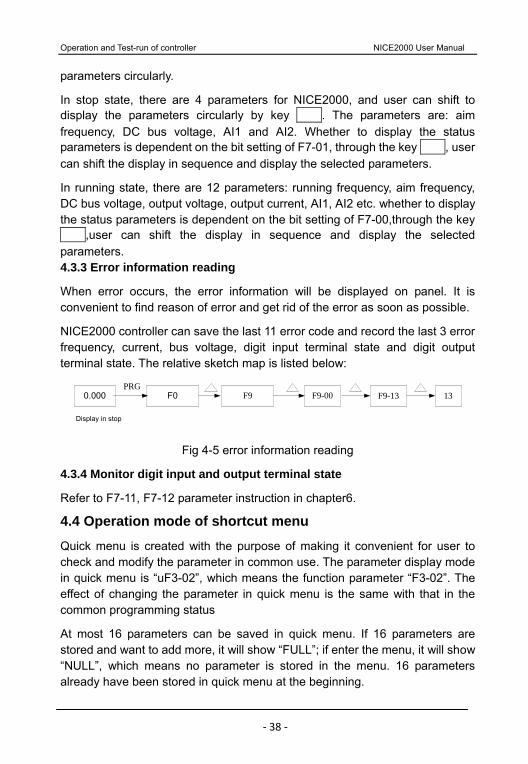
4.3.2 Switch the state display parameters by shift key
AI1DC bus voltage AI2Aim frequency
Fig 4-4 example of state display parameter switch
LED can display several status parameters when NICE2000 is in stop and running states. Detailed parameter content can refer to parameters F7-00(running parameter) ~ F7-01(stop parameter). Through key , user can shift the display in sequence and display the stopping or running state
Operation and Test-run of controller NICE2000 User Manual
‐ 38 ‐
parameters circularly.
In stop state, there are 4 parameters for NICE2000, and user can shift to display the parameters circularly by key . The parameters are: aim frequency, DC bus voltage, AI1 and AI2. Whether to display the status parameters is dependent on the bit setting of F7-01, through the key , user can shift the display in sequence and display the selected parameters.
In running state, there are 12 parameters: running frequency, aim frequency, DC bus voltage, output voltage, output current, AI1, AI2 etc. whether to display the status parameters is dependent on the bit setting of F7-00,through the key ,user can shift the display in sequence and display the selected parameters. 4.3.3 Error information reading
When error occurs, the error information will be displayed on panel. It is convenient to find reason of error and get rid of the error as soon as possible.
NICE2000 controller can save the last 11 error code and record the last 3 error frequency, current, bus voltage, digit input terminal state and digit output terminal state. The relative sketch map is listed below:
F9-00F9 F9-13F00.000PRG
13
Display in stop
Fig 4-5 error information reading
4.3.4 Monitor digit input and output terminal state
Refer to F7-11, F7-12 parameter instruction in chapter6.
4.4 Operation mode of shortcut menu
Quick menu is created with the purpose of making it convenient for user to check and modify the parameter in common use. The parameter display mode in quick menu is “uF3-02”, which means the function parameter “F3-02”. The effect of changing the parameter in quick menu is the same with that in the common programming status
At most 16 parameters can be saved in quick menu. If 16 parameters are stored and want to add more, it will show “FULL”; if enter the menu, it will show “NULL”, which means no parameter is stored in the menu. 16 parameters already have been stored in quick menu at the beginning.
NICE2000 User Manual Operation and Test-run of controller
‐ 39 ‐
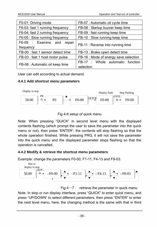
F0-01: Driving mode FB-07 : Automatic oil cycle time F6-03: fast 1 running frequency FB-08 : Startup buzzer keep time F6-04: fast 2 running frequency FB-09 : fast running keep time F6-05 : Slow running frequency FB-10 : Slow running keep time F6-09 : Examine and repair frequency
FB-11 : Reverse into running time
FB-00 : fast 1 sensor detect time FB-13 : Brake open detect time FB-03 : fast 1 host motor pulse FB-16 : Mode of energy save selection
FB-06 : Automatic oil keep time FB-17 : Whole automatic function selection
User can edit according to actual demand.
4.4.1 Add shortcut menu parameters
50.00 F0 F0-00 F0-00 F0-00PRG QUICK ENTE
R
Display in stop Display flash Stop flashing
Fig 4-6 setup of quick menu
Note: When pressing “QUICK” in second level menu with the displayed contents flashing (which prompt the user to save the parameter into the quick menu or not), then press “ENTER”; the contents will stop flashing so that the whole operation finished. While pressing PRG, it will not save the parameter into the quick menu and the displayed parameter stops flashing so that the operation is cancelled.
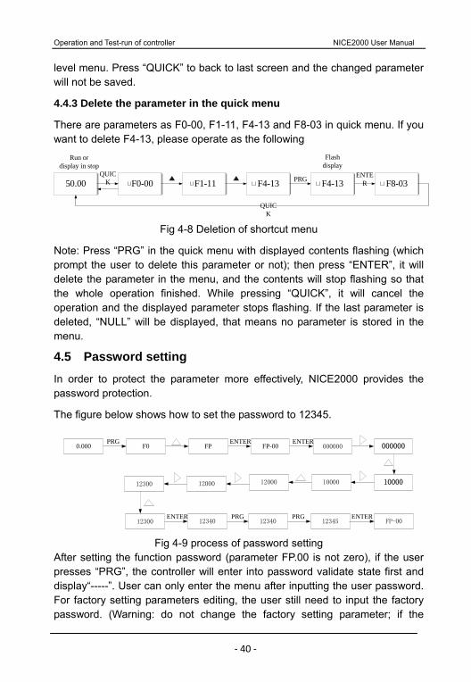
4.4.2 Modify & retrieve the shortcut menu parameters
Example: change the parameters F0-00, F1-11, F4-13 and F8-03:
50.00 F0-00 F1-11 F4-13 F8-03QUIC
K
Run or display in stop
Fig 4-7 retrieve the parameter in quick menu Note: In stop or run display interface, press “QUICK” to enter quick menu, and press “UP/DOWN” to select different parameters, then press “ENTER” to enter the next level menu, here, the changing method is the same with that in third
Operation and Test-run of controller NICE2000 User Manual
‐ 40 ‐
level menu. Press “QUICK” to back to last screen and the changed parameter will not be saved.
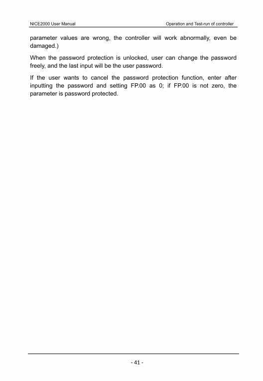
4.4.3 Delete the parameter in the quick menu
There are parameters as F0-00, F1-11, F4-13 and F8-03 in quick menu. If you want to delete F4-13, please operate as the following
50.00 F0-00 F1-11 F4-13QUIC
K F8-03ENTE
RPRG
Flash display
QUICK
F4-13
Run or display in stop
Fig 4-8 Deletion of shortcut menu
Note: Press “PRG” in the quick menu with displayed contents flashing (which prompt the user to delete this parameter or not); then press “ENTER”, it will delete the parameter in the menu, and the contents will stop flashing so that the whole operation finished. While pressing “QUICK”, it will cancel the operation and the displayed parameter stops flashing. If the last parameter is deleted, “NULL” will be displayed, that means no parameter is stored in the menu.
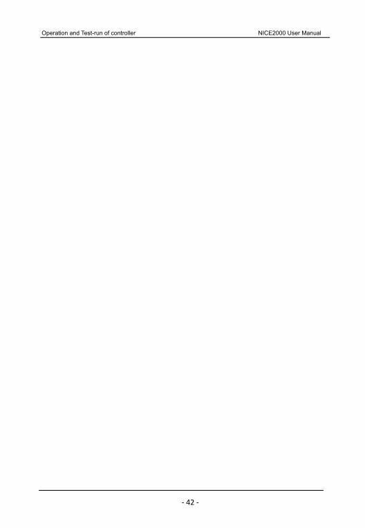
4.5 Password setting
In order to protect the parameter more effectively, NICE2000 provides the password protection.
The figure below shows how to set the password to 12345.
000000FP-00FPENTER
000000
10000100001200012000
0.000 F0PRG ENTER
12300
12300 12340ENTER
12340PRG
12345PRG
FP-00ENTER
Fig 4-9 process of password setting
After setting the function password (parameter FP.00 is not zero), if the user presses “PRG”, the controller will enter into password validate state first and display“-----”. User can only enter the menu after inputting the user password. For factory setting parameters editing, the user still need to input the factory password. (Warning: do not change the factory setting parameter; if the
NICE2000 User Manual Operation and Test-run of controller
‐ 41 ‐
parameter values are wrong, the controller will work abnormally, even be damaged.)
When the password protection is unlocked, user can change the password freely, and the last input will be the user password.
If the user wants to cancel the password protection function, enter after inputting the password and setting FP.00 as 0; if FP.00 is not zero, the parameter is password protected.
Operation and Test-run of controller NICE2000 User Manual
‐ 42 ‐
Operation and Test-run of controller NICE2000 User Manual
‐ 43 ‐
Function Parameter Table
Function Parameter Table NICE2000 User Manual
‐ 44 ‐
Chapter 5 Function parameter Table 5.1 Instruction of function parameters
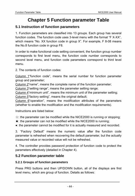
1. Function parameters are classified into 13 groups. Each group has several function codes. The function code uses 3-level menu with the format “F X-XX”, which means “No. XX function code in group X”. For example, F 8-08 means the No.8 function code in group F8.
In order to make functional code setting convenient, the function group number corresponds to first level menu, the function code number corresponds to second level menu, and function code parameters correspond to third level menu.
2. The contents of function codes:
Column 1“function code”, means the serial number for function parameter group and parameter; Column 2“name”, means the complete name of the function parameter; Column 3“setting range”, means the parameter setting range; Column 4“minimum unit”, means the minimum unit of the parameter setting; Column 5“factory setting”, means the original default; Column 6“operation”, means the modification attributes of the parameters (whether to enable the modification and the modification requirements).
Instructions are listed below:
: the parameter can be modified while the NICE2000 is running or stopping; : the parameter can not be modified while the NICE2000 is running;
: the parameter cannot be modified for it is actually measured and recorded.
3. “Factory Default” means the numeric value after the function code parameter is refreshed when recovering the default parameter, but the actually measured value or recorded value will not be refreshed.
4. The controller provides password protection of function code to protect the parameters effectively (detailed in Chapter 4).
5.2 Function parameter table
5.2.1 Groups of function parameters
Press PRG buttons and then UP/DOWN button, all of the displays are first level menu, which are group of function. Details as follows:

Operation and Test-run of controller NICE2000 User Manual
‐ 45 ‐
F0――Basic parameter F1――motor parameter F2――vector control parameter F3――VF function parameter F4――input function parameter F5――output function parameter F6――up/down control parameter
F7――assistant function parameter
F8――auxiliary managing parameter F9――protect function parameter FA――communication parameter FB――elevator function parameter FF――factory parameter FP――user parameter
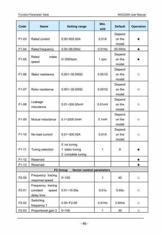
5.2.2 Function parameter table
Code Name Setting range Min. unit
Default Operation
F0 Group Basic parameter F0-00 Reserved 0~2 1 2
F0-01 Elevator drive mode
0 :operating panel control 1 :bypass variable frequency 2 :full variable frequency driving 3 :Y- direct startup
1 1
F0-02 Frequency power setting
0 : interior digit setting 1 0
F0-03 Operating panel frequency
0.00Hz~F0-04 0.01Hz 0.00Hz
F0-04 Max. frequency 50.00Hz~99.00Hz 0.01Hz 50.00Hz
F0-05 Carrier frequency 0.5~16.0kHz 0.1kHzDepend on the model
F0-06 Panel-controlled reverse running
0~1 1 0
F1 Group Motor parameter F1-00 Reserved 0~2 1 0
F1-01 Rated power 2.2~75.0kW 0.1kW Depend on the model
F1-02 Rated voltage 0~440V 1V 380V
Function Parameter Table NICE2000 User Manual
‐ 46 ‐
Code Name Setting range Min. unit
Default Operation
F1-03 Rated current 0.00~655.00A 0.01A Depend on the model
F1-04 Rated frequency 0.00~99.00Hz 0.01Hz 50.00Hz
F1-05 Rated rotate speed
0~3000rpm 1 rpm Depend on the model
F1-06 Stator resistance 0.001~30.000Ω 0.001ΩDepend on the model
F1-07 Rotor resistance 0.001~30.000Ω 0.001ΩDepend on the model
F1-08 Leakage inductance
0.01~300.00mH 0.01mHDepend on the model
F1-09 Mutual inductance 0.1~2000.0mH 0.1mH Depend on the model
F1-10 No-load current 0.01~300.00A 0.01A Depend on the model
F1-11 Tuning selection 0 :no tuning 1 :static tuning 2 :complete tuning
1 0
F1-12 Reserved
F1-13 Reserved
F2 Group Vector control parameters
F2-00 Frequency tracing response speed
0~100 1 40
F2-01 Frequency tracing constant speed delay time
0.01~10.00s 0.01s 0.60s
F2-02 Switching frequency 1
0.00~F2-05 0.01Hz 2.00Hz
F2-03 Proportional gain 2 0~100 1 30
NICE2000 User Manual Function Parameter Table
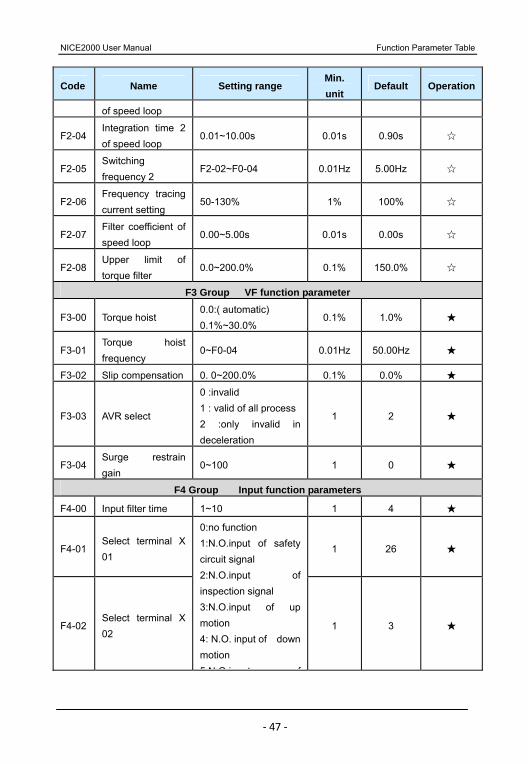
‐ 47 ‐
Code Name Setting range Min. unit
Default Operation
of speed loop
F2-04 Integration time 2 of speed loop
0.01~10.00s 0.01s 0.90s
F2-05 Switching frequency 2
F2-02~F0-04 0.01Hz 5.00Hz
F2-06 Frequency tracing current setting
50-130% 1% 100%
F2-07 Filter coefficient of speed loop
0.00~5.00s 0.01s 0.00s
F2-08 Upper limit of torque filter
0.0~200.0% 0.1% 150.0%
F3 Group VF function parameter
F3-00 Torque hoist 0.0:( automatic) 0.1%~30.0%
0.1% 1.0%
F3-01 Torque hoist frequency
0~F0-04 0.01Hz 50.00Hz
F3-02 Slip compensation 0. 0~200.0% 0.1% 0.0%
F3-03 AVR select
0 :invalid 1 : valid of all process 2 :only invalid in deceleration
1 2
F3-04 Surge restrain gain
0~100 1 0
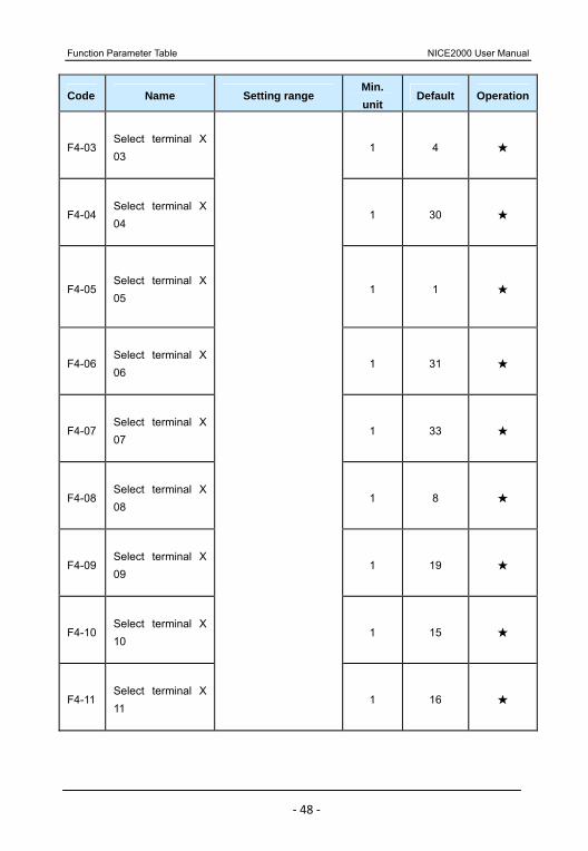
F4 Group Input function parameters
F4-00 Input filter time 1~10 1 4
F4-01 Select terminal X 01
1 26
F4-02 Select terminal X 02
0:no function 1:N.O.input of safety circuit signal 2:N.O.input of inspection signal 3:N.O.input of up motion 4: N.O. input of down motion 5:N O input of
1 3
Function Parameter Table NICE2000 User Manual
‐ 48 ‐
Code Name Setting range Min. unit
Default Operation
F4-03 Select terminal X 03
1 4
F4-04 Select terminal X 04
1 30
F4-05 Select terminal X 05
1 1
F4-06 Select terminal X 06
1 31
F4-07 Select terminal X 07
1 33
F4-08 Select terminal X 08
1 8
F4-09 Select terminal X 09
1 19
F4-10 Select terminal X 10
1 15
F4-11 Select terminal X 11
1 16
NICE2000 User Manual Function Parameter Table
‐ 49 ‐
Code Name Setting range Min. unit
Default Operation
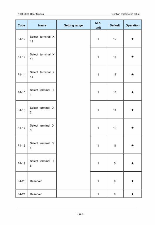
F4-12 Select terminal X 12
1 12
F4-13 Select terminal X 13
1 18
F4-14 Select terminal X 14
1 17
F4-15 Select terminal DI 1
1 13
F4-16 Select terminal DI 2
1 14
F4-17 Select terminal DI 3
1 10
F4-18 Select terminal DI 4
1 11
F4-19 Select terminal DI 5
1 5
F4-20 Reserved 1 0
F4-21 Reserved 1 0
Function Parameter Table NICE2000 User Manual
‐ 50 ‐
Code Name Setting range Min. unit
Default Operation
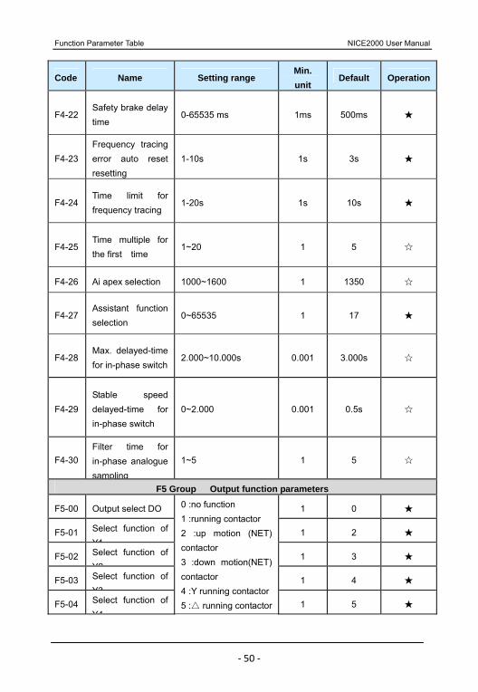
F4-22 Safety brake delay time
0-65535 ms 1ms 500ms
F4-23 Frequency tracing error auto reset resetting
1-10s 1s 3s
F4-24 Time limit for frequency tracing
1-20s 1s 10s
F4-25 Time multiple for the first time
1~20 1 5
F4-26 Ai apex selection 1000~1600 1 1350
F4-27 Assistant function selection
0~65535 1 17
F4-28 Max. delayed-time for in-phase switch
2.000~10.000s 0.001 3.000s
F4-29 Stable speed delayed-time for in-phase switch
0~2.000 0.001 0.5s
F4-30 Filter time for in-phase analogue sampling
1~5 1 5
F5 Group Output function parameters
F5-00 Output select DO 1 0
F5-01 Select function of Y1
1 2
F5-02 Select function of Y2
1 3
F5-03 Select function of Y3
1 4
F5-04 Select function of Y4
0 :no function 1 :running contactor 2 :up motion (NET) contactor 3 :down motion(NET) contactor 4 :Y running contactor5 : running contactor 1 5
NICE2000 User Manual Function Parameter Table
‐ 51 ‐
Code Name Setting range Min. unit
Default Operation
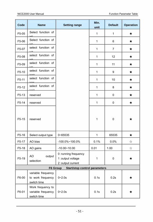
F5-05 Select function of Y5
1 1
F5-06 Select function of Y6
1 6
F5-07 select function of Y7
1 7
F5-08 select function of Y8
1 12
F5-09 select function of Y9
1 11
F5-10 select function of Y10
1 9
F5-11 select function of Y11
1 10
F5-12 select function of Y12
1 8
F5-13 reserved 1 0
F5-14 reserved 1 0
F5-15 reserved 1 0
F5-16 Select output type 0~65535 1 65535
F5-17 AO bias -100.0%~100.0% 0.1% 0.0%
F5-18 AO gains -10.00~10.00 0.01 1.00
F5-19 AO output selection
0 :running frequency 1 :output voltage 2 :output current
1 0
F6 Group Start/stop control parameters
F6-00 variable frequency to work frequency switch time
0~2.0s 0.1s 0.2s
F6-01 Work frequency to variable frequency switch time
0~2.0s 0.1s 0.2s

Function Parameter Table NICE2000 User Manual
‐ 52 ‐
Code Name Setting range Min. unit
Default Operation
F6-02 Conversion switch frequency
0~50.0Hz 0.01 43.0Hz
F6-03 Quick 1 running frequency
0~Max.frequency 0.01Hz 50.00Hz
F6-04 Quick 2 running frequency
0~Max.frequency 0.01Hz 30.00Hz
F6-05 Slow running frequency
0~Max.frequency 0.01Hz 20.00Hz
F6-06 Star- triangular switch of time extension
0~500MS 1MS 100MS
F6-07 Accelerate time 0.0~3000.0s 0.1s 4.0s
F6-08 Decelerate time 0.0~3000.0s 0.1s 60.0s
F6-09 Examining and repairing frequency
0.00~Max.frequency 0.01Hz 25.00Hz
F6-10 Inching (examine and repair) accelerate time
0.0~3000.0s 0.1s 20.0s
F6-11 Selection of inspection mode
0~1 1 0
F6-12 Up-frequency switch surplus
0~10.00Hz 0.01Hz 1.50Hz
F6-13 Down-frequency switch surplus
0~10.00Hz 0.01HZ 1.50HZ
F7 Group Assistant function parameters
F7-00 Running parameter display
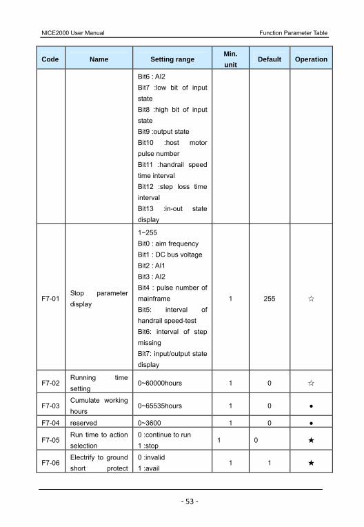
1~16383 Bit0 :running frequency Bit1 :aim frequency Bit2 :DC bus voltage Bit3 :output voltage Bit4 :output current Bit5 : AI1
1 16383
NICE2000 User Manual Function Parameter Table
‐ 53 ‐
Code Name Setting range Min. unit
Default Operation
Bit6 : AI2 Bit7 :low bit of input state Bit8 :high bit of input state Bit9 :output state Bit10 :host motor pulse number Bit11 :handrail speed time interval Bit12 :step loss time interval Bit13 :in-out state display
F7-01 Stop parameter display
1~255 Bit0 : aim frequency Bit1 : DC bus voltage Bit2 : AI1 Bit3 : AI2 Bit4 : pulse number of mainframe Bit5: interval of handrail speed-test Bit6: interval of step missing Bit7: input/output state display
1 255
F7-02 Running time setting
0~60000hours 1 0
F7-03 Cumulate working hours
0~65535hours 1 0
F7-04 reserved 0~3600 1 0
F7-05 Run time to action selection
0 :continue to run 1 :stop
1 0
F7-06 Electrify to ground short protect
0 :invalid 1 :avail
1 1
Function Parameter Table NICE2000 User Manual
‐ 54 ‐
Code Name Setting range Min. unit
Default Operation
detection
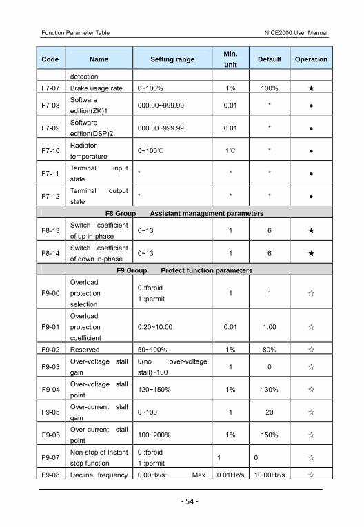
F7-07 Brake usage rate 0~100% 1% 100%
F7-08 Software edition(ZK)1
000.00~999.99 0.01 *
F7-09 Software edition(DSP)2
000.00~999.99 0.01 *
F7-10 Radiator temperature
0~100 1 *
F7-11 Terminal input state
* * *
F7-12 Terminal output state
* * *
F8 Group Assistant management parameters
F8-13 Switch coefficient of up in-phase
0~13 1 6
F8-14 Switch coefficient of down in-phase
0~13 1 6
F9 Group Protect function parameters
F9-00 Overload protection selection
0 :forbid 1 :permit
1 1
F9-01 Overload protection coefficient
0.20~10.00 0.01 1.00
F9-02 Reserved 50~100% 1% 80%
F9-03 Over-voltage stall gain
0(no over-voltage stall)~100
1 0
F9-04 Over-voltage stall point
120~150% 1% 130%
F9-05 Over-current stall gain
0~100 1 20
F9-06 Over-current stall point
100~200% 1% 150%
F9-07 Non-stop of Instant stop function
0 :forbid 1 :permit
1 0
F9-08 Decline frequency 0.00Hz/s~ Max. 0.01Hz/s 10.00Hz/s
NICE2000 User Manual Function Parameter Table
‐ 55 ‐
Code Name Setting range Min. unit
Default Operation
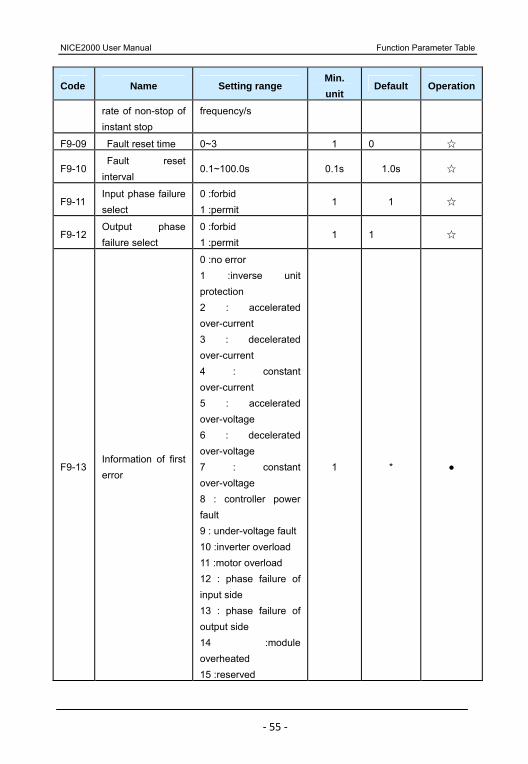
rate of non-stop of instant stop
frequency/s
F9-09 Fault reset time 0~3 1 0
F9-10 Fault reset interval
0.1~100.0s 0.1s 1.0s
F9-11 Input phase failure select
0 :forbid 1 :permit
1 1
F9-12 Output phase failure select
0 :forbid 1 :permit
1 1
F9-13 Information of first error
0 :no error 1 :inverse unit protection 2 : accelerated over-current 3 : decelerated over-current 4 : constant over-current 5 : accelerated over-voltage 6 : decelerated over-voltage 7 : constant over-voltage 8 : controller power fault 9 : under-voltage fault10 :inverter overload 11 :motor overload 12 : phase failure of input side 13 : phase failure of output side 14 :module overheated 15 :reserved
1 *
Function Parameter Table NICE2000 User Manual
‐ 56 ‐
Code Name Setting range Min. unit
Default Operation
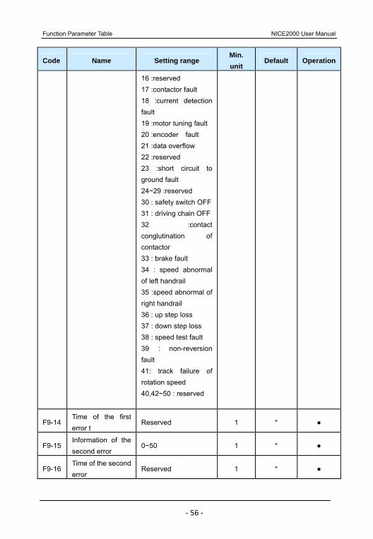
16 :reserved 17 :contactor fault 18 :current detection fault 19 :motor tuning fault 20 :encoder fault 21 :data overflow 22 :reserved 23 :short circuit to ground fault 24~29 :reserved 30 : safety switch OFF31 : driving chain OFF32 :contact conglutination of contactor 33 : brake fault 34 : speed abnormal of left handrail 35 :speed abnormal of right handrail 36 : up step loss 37 : down step loss 38 : speed test fault 39 : non-reversion fault 41: track failure of rotation speed 40,42~50 : reserved
F9-14 Time of the first error t
Reserved 1 *
F9-15 Information of the second error
0~50 1 *
F9-16 Time of the second error
Reserved 1 *
NICE2000 User Manual Function Parameter Table
‐ 57 ‐
Code Name Setting range Min. unit
Default Operation
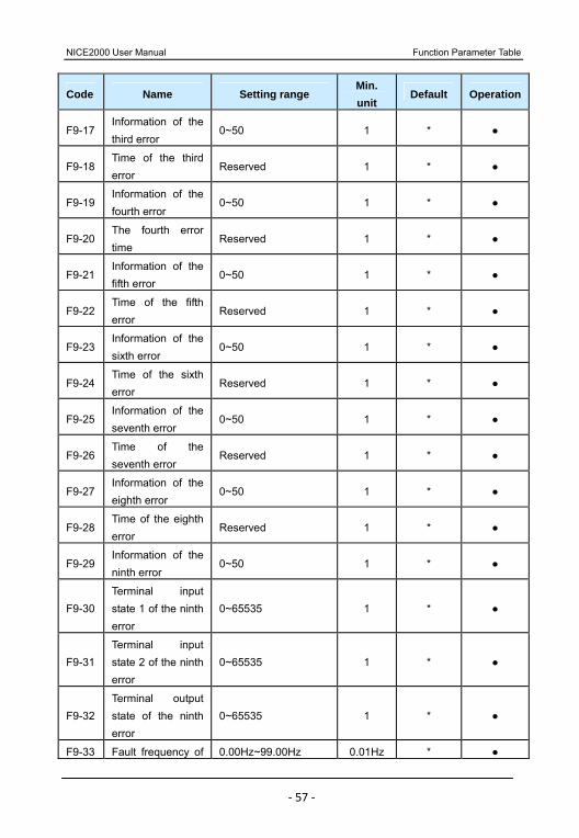
F9-17 Information of the third error
0~50 1 *
F9-18 Time of the third error
Reserved 1 *
F9-19 Information of the fourth error
0~50 1 *
F9-20 The fourth error time
Reserved 1 *
F9-21 Information of the fifth error
0~50 1 *
F9-22 Time of the fifth error
Reserved 1 *
F9-23 Information of the sixth error
0~50 1 *
F9-24 Time of the sixth error
Reserved 1 *
F9-25 Information of the seventh error
0~50 1 *
F9-26 Time of the seventh error
Reserved 1 *
F9-27 Information of the eighth error
0~50 1 *
F9-28 Time of the eighth error
Reserved 1 *
F9-29 Information of the ninth error
0~50 1 *
F9-30 Terminal input state 1 of the ninth error
0~65535 1 *
F9-31 Terminal input state 2 of the ninth error
0~65535 1 *
F9-32 Terminal output state of the ninth error
0~65535 1 *
F9-33 Fault frequency of 0.00Hz~99.00Hz 0.01Hz *
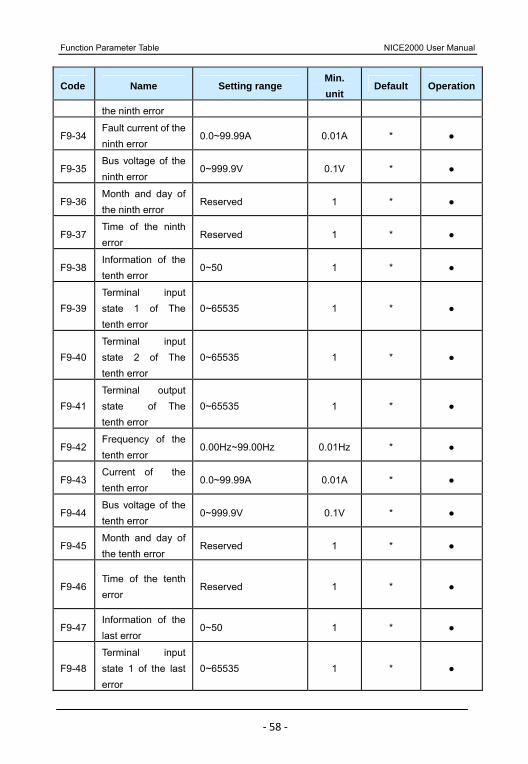
Function Parameter Table NICE2000 User Manual
‐ 58 ‐
Code Name Setting range Min. unit
Default Operation
the ninth error
F9-34 Fault current of the ninth error
0.0~99.99A 0.01A *
F9-35 Bus voltage of the ninth error
0~999.9V 0.1V *
F9-36 Month and day of the ninth error
Reserved 1 *
F9-37 Time of the ninth error
Reserved 1 *
F9-38 Information of the tenth error
0~50 1 *
F9-39 Terminal input state 1 of The tenth error
0~65535 1 *
F9-40 Terminal input state 2 of The tenth error
0~65535 1 *
F9-41 Terminal output state of The tenth error
0~65535 1 *
F9-42 Frequency of the tenth error
0.00Hz~99.00Hz 0.01Hz *
F9-43 Current of the tenth error
0.0~99.99A 0.01A *
F9-44 Bus voltage of the tenth error
0~999.9V 0.1V *
F9-45 Month and day of the tenth error
Reserved 1 *
F9-46 Time of the tenth error
Reserved 1 *
F9-47 Information of the last error
0~50 1 *
F9-48 Terminal input state 1 of the last error
0~65535 1 *
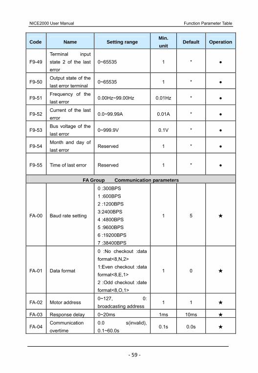
NICE2000 User Manual Function Parameter Table
‐ 59 ‐
Code Name Setting range Min. unit
Default Operation
F9-49 Terminal input state 2 of the last error
0~65535 1 *
F9-50 Output state of the last error terminal
0~65535 1 *
F9-51 Frequency of the last error
0.00Hz~99.00Hz 0.01Hz *
F9-52 Current of the last error
0.0~99.99A 0.01A *
F9-53 Bus voltage of the last error
0~999.9V 0.1V *
F9-54 Month and day of last error
Reserved 1 *
F9-55 Time of last error Reserved 1 *
FA Group Communication parameters
FA-00 Baud rate setting
0 :300BPS 1 :600BPS 2 :1200BPS 3:2400BPS 4 :4800BPS 5 :9600BPS 6 :19200BPS 7 :38400BPS
1 5
FA-01 Data format
0 :No checkout :data format<8,N,2> 1:Even checkout :data format<8,E,1> 2 :Odd checkout :date format<8,O,1>
1 0
FA-02 Motor address 0~127, 0: broadcasting address
1 1
FA-03 Response delay 0~20ms 1ms 10ms
FA-04 Communication overtime
0.0 s(invalid), 0.1~60.0s
0.1s 0.0s
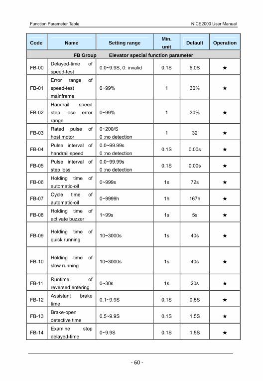
Function Parameter Table NICE2000 User Manual
‐ 60 ‐
Code Name Setting range Min. unit
Default Operation
FB Group Elevator special function parameter
FB-00 Delayed-time of speed-test
0.0~9.9S, 0: invalid 0.1S 5.0S
FB-01 Error range of speed-test mainframe
0~99% 1 30%
FB-02 Handrail speed step lose error range
0~99% 1 30%
FB-03 Rated pulse of host motor
0~200/S 0 :no detection
1 32
FB-04 Pulse interval of handrail speed
0.0~99.99s 0 :no detection
0.1S 0.00s
FB-05 Pulse interval of step loss
0.0~99.99s 0 :no detection
0.1S 0.00s
FB-06 Holding time of automatic-oil
0~999s 1s 72s
FB-07 Cycle time of automatic-oil
0~9999h 1h 167h
FB-08 Holding time of activate buzzer
1~99s 1s 5s
FB-09 Holding time of quick running
10~3000s 1s 40s
FB-10 Holding time of slow running
10~3000s 1s 40s
FB-11 Runtime of reversed entering
0~30s 1s 20s
FB-12 Assistant brake time
0.1~9.9S 0.1S 0.5S
FB-13 Brake-open detective time
0.5~9.9S 0.1S 1.5S
FB-14 Examine stop delayed-time
0~9.9S 0.1S 1.5S
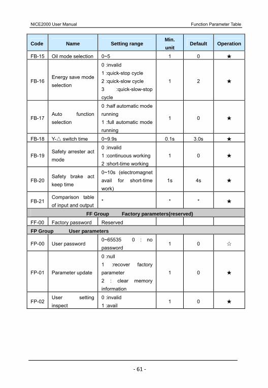
NICE2000 User Manual Function Parameter Table
‐ 61 ‐
Code Name Setting range Min. unit
Default Operation
FB-15 Oil mode selection 0~5 1 0
FB-16 Energy save mode selection
0 :invalid 1 :quick-stop cycle 2 :quick-slow cycle 3 :quick-slow-stop cycle
1 2
FB-17 Auto function selection
0 :half automatic mode running 1 :full automatic mode running
1 0
FB-18 Y- switch time 0~9.9s 0.1s 3.0s
FB-19 Safety arrester act mode
0 :invalid 1 :continuous working 2 :short-time working
1 0
FB-20 Safety brake act keep time
0~10s (electromagnet avail for short-time work)
1s 4s
FB-21 Comparison table of input and output
* * *
FF Group Factory parameters(reserved) FF-00 Factory password Reserved
FP Group User parameters
FP-00 User password 0~65535 0 : no password
1 0
FP-01 Parameter update
0 :null 1 :recover factory parameter 2 : clear memory information
1 0
FP-02 User setting inspect
0 :invalid 1 :avail
1 0
Function Parameter Table NICE2000 User Manual
‐ 62 ‐
Operation and Test-run of controller NICE2000 User Manual
‐ 63 ‐
Instruction of function parameter

Instruction of function parameter NICE2000 User Manual
‐ 64 ‐
Chapter 6 Instruction of function parameter 6.1 F0 Group Basic parameter
Driving mode Default 1 Min. unit 1
F0-01 Setting range 0,1,2,3
It can set the mode of running command and running speed of the system.
0: 0perating panel control
Use the key “RUN” and “STOP” to control the machine, and the running speed is determined by F0-03 (running frequency of panel control). This running mode is mainly used for the debugging process of NICE2000.
When NICE2000 is in running, we have 3 ways to control the elevator:
1: Bypass conversion frequency drive
When in this mode, NICE2000 will automatically select variable frequency drive or work frequency drive according to the state of elevator (example: if there is any passenger). When no passenger is on the elevator, it will switch from work frequency to variable frequency; while having passengers, the elevator will accelerate, switching to work frequency.
2. Complete conversion frequency drive
In this mode, whether the running speed of the elevator is high or low, NICE2000 adopts variable frequency drive constantly. NICE2000 automatically control the speed according to the passenger state: no passenger, variable frequency at energy saving low running; while having passengers, variable frequency accelerate to high running.
3. Y- direct start
NICE2000 will use Y- to startup di rectly instead of variable frequency drive in this mode. When over-current fault happens, Y- can remain running
normally.
Frequency power setting
Default 0 Min. unit 1 F0-02
setting range 0

NICE2000 User Manual Instruction of function parameter
‐ 65 ‐
0: interior figure setting
Operating panel
running frequency
Default 0.00Hz Min. unit 0.01Hz F0-03
setting range 0.00Hz~F0-04
This function code is valid only when F0-01=0.
It sets up the initial default of speed when the elevator is controlled by panel operation. Once the value is set up, it can never be lost even when electric is cut off. User can change this function code to change the running speed.
Max. frequency 50Hz
Depend on the model
Min. unit 0.01Hz F0-04
setting range 50.00Hz~99.00Hz
Set the max. output power of system.
Carrier frequency Default
Depending on the model
Min. unit 0.1KHz F0-05
setting range 0.5~16.0kHz
The magnitude of carry frequency is highly correlative to motor running. The carrier frequency generally is set upward10 KHz to travel without noise. It is suggested to reduce the carry frequency within noise allowing range.
When the carrier frequency is low, the output current higher-harmonic increases, and the consumption as well as elevated temperature of motor will increase.
When the carrier frequency is high, the consumption as well as elevated temperature of motor will decline, but the consumption, elevated temperature and interference of the system will all increase.
To regulate the carrier frequency will exert influences on the following performance:
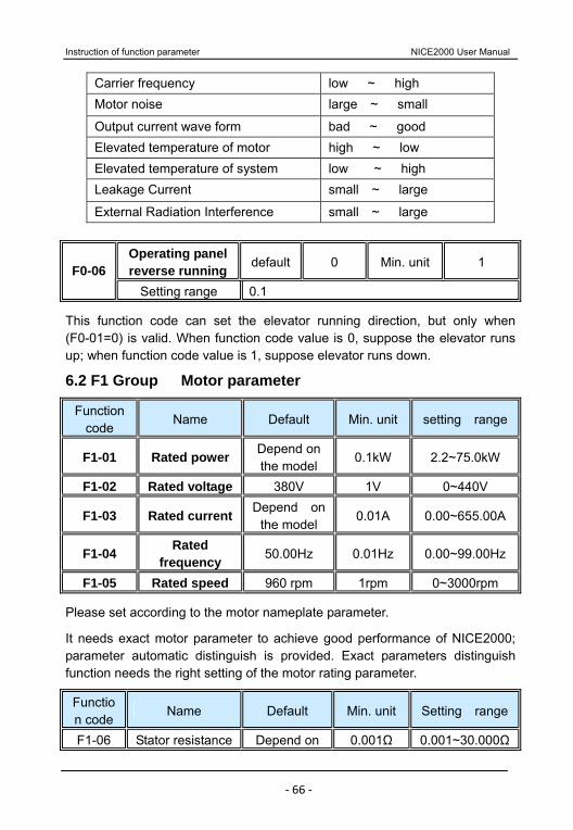
Instruction of function parameter NICE2000 User Manual
‐ 66 ‐
Carrier frequency low ~ high Motor noise large ~ small
Output current wave form bad ~ good Elevated temperature of motor high ~ low Elevated temperature of system low ~ high Leakage Current small ~ large
External Radiation Interference small ~ large
Operating panel reverse running default 0 Min. unit 1 F0-06
Setting range 0.1
This function code can set the elevator running direction, but only when (F0-01=0) is valid. When function code value is 0, suppose the elevator runs up; when function code value is 1, suppose elevator runs down.
6.2 F1 Group Motor parameter
Function code
Name Default Min. unit setting range
F1-01 Rated power Depend on the model
0.1kW 2.2~75.0kW
F1-02 Rated voltage 380V 1V 0~440V
F1-03 Rated current Depend on the model
0.01A 0.00~655.00A
F1-04 Rated frequency 50.00Hz 0.01Hz 0.00~99.00Hz
F1-05 Rated speed 960 rpm 1rpm 0~3000rpm
Please set according to the motor nameplate parameter.
It needs exact motor parameter to achieve good performance of NICE2000; parameter automatic distinguish is provided. Exact parameters distinguish function needs the right setting of the motor rating parameter.
Function code
Name Default Min. unit Setting range
F1-06 Stator resistance Depend on 0.001Ω 0.001~30.000Ω
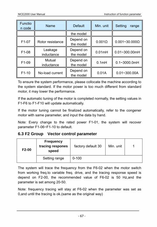
NICE2000 User Manual Instruction of function parameter
‐ 67 ‐
Function code
Name Default Min. unit Setting range
the model
F1-07 Rotor resistanceDepend on the model
0.001Ω 0.001~30.000Ω
F1-08 Leakage
inductance Depend on the model
0.01mH 0.01~300.00mH
F1-09 Mutual
inductance Depend on the model
0.1mH 0.1~3000.0mH
F1-10 No-load currentDepend on the model
0.01A 0.01~300.00A
To ensure the system performance, please collocate the machine according to the system standard. If the motor power is too much different from standard motor, it may lower the performance.
If the automatic tuning of the motor is completed normally, the setting values in F1-F6 to F1-F10 will update automatically.
If the motor tuning cannot be finalized automatically, refer to the congener motor with same parameter, and input the data by hand.
Note: Every change to the rated power F1-01, the system will recover parameter F1-06~F1-10 to default.
6.3 F2 Group Vector control parameter
Frequency tracing respones
speed factory default 30 Min. unit 1
F2-00
Setting range 0-100
The system will trace the frequency from the F6-02 when the motor switch from working freq.to variable freq. drive, and the tracing response speed is depend on F2-00, the recommended value of F6-02 is 50 Hz,and the parameter is set among 20-50.
Note: frequency tracing will stay at F6-02 when the parameter was set as 0,and until the tracing is ok.(same as the original way)

Instruction of function parameter NICE2000 User Manual
‐ 68 ‐
Freq.tracing constant
speed delay time
Factory default
0.60s Min.unit 0.01 F2-01
Settinfg range 0.01-10.00s
When the escalator switch from the work freq.to variable freq., it will run with the constant freq.as tracing .The motor will run at decrese freq. after the F2-01 setting time.this parameter needs no modification.
Function code
Name Default Min. unitSetting range
F2-02 Switching frequency 1 2.00Hz 0.01Hz0.00~F2-0
5Hz
F2-03 Proportional gain of speed
loop 2 30 1 0~100
F2-04 Integration time of speed
loop 2 0.80s 0.01s
0.01~10.00s
F2-05 Switching frequency 2 5.00Hz 0.01HzF2-02~F0-
04Hz
Freq. tracing current setting
Default 100% Min. unit 1% F2-06
setting range 50~130%
The system will trace the freq. with the current of F2-06. This parameter needs no modification.
Filter coefficient of speed loop Default
0.00s
Min. unit 0.01s F2-07 setting range 0.00~5.00s
This function code is the filter time of ASR output (torque current), current sampling and speed feedback. Generally speaking, we don’t need to adjust the parameter; when there is strong interference, just add time constant.
The output of speed regulator refers to the torque current command to the controller. The filter time constant of speed loop refers to the filter time of the torque current command.
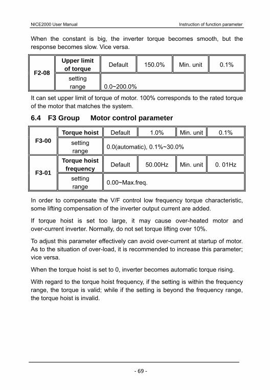
NICE2000 User Manual Instruction of function parameter
‐ 69 ‐
When the constant is big, the inverter torque becomes smooth, but the response becomes slow. Vice versa.
Upper limit of torque Default 150.0% Min. unit 0.1%
F2-08 setting range 0.0~200.0%
It can set upper limit of torque of motor. 100% corresponds to the rated torque of the motor that matches the system.
6.4 F3 Group Motor control parameter
Torque hoist Default 1.0% Min. unit 0.1% F3-00 setting
range 0.0(automatic), 0.1%~30.0%
Torque hoist frequency Default 50.00Hz Min. unit 0. 01Hz
F3-01 setting range
0.00~Max.freq.
In order to compensate the V/F control low frequency torque characteristic, some lifting compensation of the inverter output current are added.
If torque hoist is set too large, it may cause over-heated motor and over-current inverter. Normally, do not set torque lifting over 10%.
To adjust this parameter effectively can avoid over-current at startup of motor. As to the situation of over-load, it is recommended to increase this parameter; vice versa.
When the torque hoist is set to 0, inverter becomes automatic torque rising.
With regard to the torque hoist frequency, if the setting is within the frequency range, the torque is valid; while if the setting is beyond the frequency range, the torque hoist is invalid.

Instruction of function parameter NICE2000 User Manual
‐ 70 ‐
Fig 6-3 Hand-operated torque hoist
Slip compensation Default 0.0% Min. unit 0.1%
F3-02 setting range 0.0%~200.0%
AVR select Default 1 Min. unit 2 F3-03 setting range 0, 1, 2
oscillating restrain gain Default 0 Min. unit 1 F3-04 setting range 0~100
F3-02 Slip compensation is effective for V/F control. To set this parameter can compensate the slip load when it is V/F controlled, minishing the change of motor rotation generated due to the variation of the load; generally, 100% corresponds to rated slip when the motor with rated load. We can adjust slip coefficient referring to following principle: when slip compensate coefficient is set up to 100% with rated load, the rotation of the inverter motor is basically close to given speed. If with lower load, this coefficient can be less than 100%; and if with lager load, this coefficient can also be larger than 100%.
F3-03 AVR (automatic steady voltage function) select. In the V/F control mode, when need quick stop but without brake resistance, selecting 2 “only valid when decelerated” can greatly reduce the possibility of the over voltage fault alarm; but at the circs of having brake resistance or quick decelerate unnecessary, please select 1 “whole process valid”.
F3-04 oscillating restrain gain, when motor has no oscillating phenomena, please select the parameter to 0. Only when motor have obvious oscillating
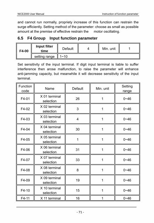
NICE2000 User Manual Instruction of function parameter
‐ 71 ‐
and cannot run normally, propriety increase of this function can restrain the surge efficiently. Setting method of the parameter: choose as small as possible amount at the premise of effective restrain the motor oscillating.
6.5 F4 Group Input function parameter
Input filter time Default 4 Min. unit 1 F4-00
setting range 1~10
Set sensitivity of the input terminal. If digit input terminal is liable to suffer interference then arose malfunction, to raise the parameter will enhance anti-jamming capacity, but meanwhile it will decrease sensitivity of the input terminal.
Function code
Name Default Min. unit Setting range
F4-01 X 01 terminal
selection 26 1 0~46
F4-02 X 02 terminal
selection 3 1 0~46
F4-03 X 03 terminal
selection 4 1 0~46
F4-04 X 04 terminal
selection 30 1 0~46
F4-05 X 05 terminal
selection 1 1 0~46
F4-06 X 06 terminal
selection 31 1 0~46
F4-07 X 07 terminal
selection 33 1 0~46
F4-08 X 08 terminal
selection 8 1 0~46
F4-09 X 09 terminal
selection 19 1 0~46
F4-10 X 10 terminal
selection 15 1 0~46
F4-11 X 11 terminal 16 1 0~46

Instruction of function parameter NICE2000 User Manual
‐ 72 ‐
selection
F4-12 X 12 terminal
selection 12 1 0~46
F4-13 X 13 terminal
selection 18 1 0~46
F4-14 X 14 terminal
selection 17 1 0~46
F4-15 DI 1 terminal
selection 13 1 0~46
F4-16 DI 2 terminal
selection 14 1 0~46
F4-17 DI 3 terminal
selection 10 1 0~46
F4-18 DI 4 terminal
selection 11 1 0~46
F4-19 DI 5 terminal
selection 5 1 0~46
X01~X14, DI1~DI5 are switch input terminals, and they can select corresponding function codes 00~46, the same function code cannot be used repeatedly.
Every function has corresponding code. The code of every function is as follows:
00 No function: The controller does not work even if the signal is input. Set the unused terminals as none to prevent error work.
01 N.O. input of safety circuit signal It is an important guarantee of lift safety running, including a lot of safety switch device. Any fault happened to safety circuit will cause to the elevator’s direct stop. So it is a necessary condition of elevator running.
02 N.O. input of inspect signal 03 N.O. input of up motion 04 N.O. input of down motion Insert examine handle into examine interface of upper/ down machine room, and elevator will come to examine state. When examine signal is input to the NICE2000 system, the system will cancel whole normal running into examine
NICE2000 User Manual Instruction of function parameter
‐ 73 ‐
circs. When having examine up signal or examine down signal input to the system, elevator is running with examine speed.
05 N.O. input of host motor test speed signal For the sake of elevator safety, we need monitor the motor running speed. When host motor test speed pulse shows abnormity, NICE2000 will protect it; consequently ensure the elevator safety. After this signal receives sensor signal which is transmitted by the motor, it will judge the speed of operation.
06 N.O. input of contact conglutination signal Monitor the overall work contactor to avoid the elevator’s next running when any of the contactors has conglutination fault.
07 N.O. input of drive chain detect Drive chain’s rupture will directly threaten the running safety of the elevator, and it is also one of the important conditions of additional safety arrester brake work. NICE2000 controller judges drive chain abnormity or not according to this input.
08 N.O. input of brake detection Open or close work arrester (brake) will directly influence the normal work. To avoid motor running with brake, the detection is necessary.
09 N.O. input of non-reversion detect In order to avoid non-operate reverse protection, the test can effectively avoid the situation of up process reverse to downgrade, but it doesn’t need to consider in the state of downgrade.
10 N.O. input of up photo electricity 11 N.O. input of down photo electricity 12 N.O. input of energy save selection Energy save switch is used to set the elevator state (at hand or automatic). At the state of automatic energy save, up-down photoelectricity detect switch can monitor the passengers. NICE2000 dispose automatic energy save running through these two signals.
Energy save selection valid indicates that the controller is in the automatic running state.
13 N.O. input of left handrail speed 14 N.O. input of right handrail speed The running speed of the left/right armrest strap is separately monitored, to avoid the elevator stop running when the armrest appear abnormity and output

Instruction of function parameter NICE2000 User Manual
‐ 74 ‐
alarm.
15 N.O. input of up step loss 16 N.O. input of down step loss Up/down step of the running process is separately monitored, to avoid the elevator stop running when the step loss, and output alarm.
17 N.O. input of variable frequency speed selection When the elevator needs diverse speed, the signal can adjust the speed selection by hand (only the quick running state). When this signal is valid, the quick frequency of NICE2000 is the setting parameter of quick 2 frequency. This function is valid both in the bypass variable frequency and complete variable frequency.
18 N.O. input of driving mode selection This signal can select elevator Y- circs running with high PRI, when the
signal is effective, even if F0-01set up to bypass variable frequency or complete variable frequency, NICE2000 will come into elevator Y- circs
running.
19 N.O. input of fire signal When have fire alarm, this signal can cut off lift running signal.
20 N.O. input of fault reset External fault reset terminal signal.
21 N.O. input of stop signal The signal available indicates lift in the stop state, as well as NICE2000.
22 N.O. input of normal parallel connection When NICE2000 is used to connect in parallel, it needs to identify if the external signal of NICE2000 normal or not. Only when both controllers are in normal state, can we make parallel connection.
Options 25~46 They are the N.C. signal points of the above mentioned options with same functions.
Safety brake delaying time
default 500ms Min. unit
1ms F4-22 Setting range 0- 65535ms
The escalator will output safety brake after this parameter set time when the drive chain broken or over-speed and reversion error occur.
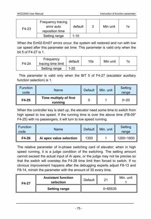
NICE2000 User Manual Instruction of function parameter
‐ 75 ‐
Frequency tracing error auto
reposition time default 3 Min unit 1s
F4-23
Setting range 1-10
When the Em02-Em07 errors occur, the system will restored and run with low car speed after this parameter set time. This parameter is valid only when the bit 5 of F4-27 is 1.
Frequency tracing time limit
default 10s Min unit 1s F4-24
Setting range 1-20
This parameter is valid only when the BIT 5 of F4-27 (escalator auxiliary function selection) is 1.
Function code
Name Default Min. unitSetting range
F4-25 Time multiply of first running 5 1 0~20
When the controller key is start up, the elevator need some time to switch from high speed to low speed. If the running time is over the above time (FB-09* F4-25) with no passengers, it will turn to low speed running.
Function code
Name Default Min. unitSetting range
F4-26 Ai apex value selection 1350 1 1200~1600
The relative parameter of in-phase switching card of elevator; when in high speed running, it is a judge condition of the switching. The setting amount cannot exceed the actual input of Ai apex, or the judge may not be precise so that the switch will overstep the F4-28 time limit then forced to switch. If no obvious improvement happens after the debugging experts adjust F8-13 and F8-14, minish the parameter with the amount of 30 every time.
Assistant function selection Default 21
Min. unit 1 F4-27
Setting range 0~65535
Instruction of function parameter NICE2000 User Manual
‐ 76 ‐
Bit 5,Bit 7 are the new added, and the default 21 is corresponding to Bit 0,Bit 2,Bit 4 valid.
BIT0 0: The inverted photoelectricity doesn’t work, which means the elevator will not accelerate in case of passenger entering in reversed direction in decelerating process or low speed climbing. 1: The elevator will accelerate to high speed running, when there are passengers entering in reversed direction. Bit 1
Set as 0: high speed startup, after key switch action, escalator reach high speed running state.
Set as 1: low speed startup ,after key switch action, escalator reach low speed running state.
BIT2 0: Monitor the mainframe both in high speed running and low speed running. 1: Monitor the mainframe only in high speed running.
BIT3 0: Alarm only once when having fault. 1: Impulse alarm when having fault.
BIT4 0: Alarm at once, when having fault. 1: Alarm only when having successive faults. Bit 5 0: if the system can not trace the frequency after 15s, E41 tracing error reported. 1:Err01- Err 07 occur, the system will restored and startup with slow car speed after F4-23’s setting time. If no such errors, there is no frequency tracing anymore and system turn to slow car startup. Bit 6 reserved Bit 7 0: reversion judgment through reversion switch. 1: reversion judgment through 2 photoelectricity signals A and B, WIRING :A connected to D15 terminal and B connected to D11 terminal . Function selection of D11 (F4-15) needs no settings. Bit 8 0: up/down command need only touching off signal
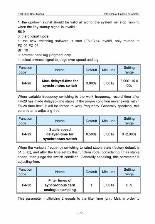
NICE2000 User Manual Instruction of function parameter
‐ 77 ‐
1: the up/down signal should be valid all along, the system will stop running when the key startup signal is invalid. Bit 9 0: the original mode 1: the new switching software is start (F8-13,14 invalid, only related to FC-00-FC-05 BIT 10 0: armrest band lag judgment only 1: select armrest signal to judge over-speed and lag.
Function code
Name Default Min. unitSetting range
F4-28 Max. delayed-time for synchronous switch 3.000s 0.001s
2.000~10.000s
When variable frequency switching to the work frequency, record time after F4-29 has made delayed-time stable. If the proper condition never exists within F4-28 time limit, it will be forced to work frequency. Generally speaking, this parameter is adjusting-free
Function code
Name Default Min. unitSetting range
F4-29 Stable speed
delayed-time for synchronous switch
0.500s 0.001s 0~2.000s
When the variable frequency switching to rated stable state (factory default is 51.5 Hz), and after the time set by this function code, considering it has stable speed, then judge the switch condition. Generally speaking, this parameter is adjusting-free.
Function code
Name Default Min. unitSetting range
F4-30 Filter times of
synchronous card analogue sampling
1 0.001s 0~9
This parameter multiplying 2 equals to the filter time (unit: Ms), in order to
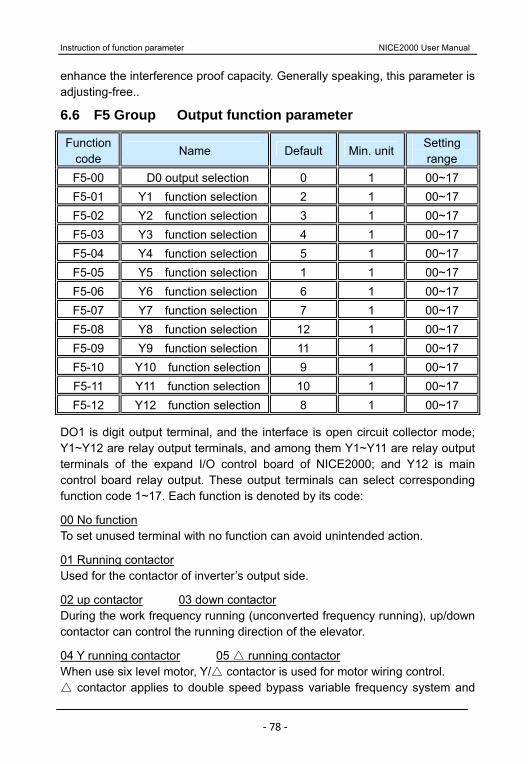
Instruction of function parameter NICE2000 User Manual
‐ 78 ‐
enhance the interference proof capacity. Generally speaking, this parameter is adjusting-free..
6.6 F5 Group Output function parameter
Function code
Name Default Min. unitSetting range
F5-00 D0 output selection 0 1 00~17 F5-01 Y1 function selection 2 1 00~17 F5-02 Y2 function selection 3 1 00~17 F5-03 Y3 function selection 4 1 00~17 F5-04 Y4 function selection 5 1 00~17 F5-05 Y5 function selection 1 1 00~17 F5-06 Y6 function selection 6 1 00~17 F5-07 Y7 function selection 7 1 00~17 F5-08 Y8 function selection 12 1 00~17 F5-09 Y9 function selection 11 1 00~17 F5-10 Y10 function selection 9 1 00~17 F5-11 Y11 function selection 10 1 00~17 F5-12 Y12 function selection 8 1 00~17
DO1 is digit output terminal, and the interface is open circuit collector mode; Y1~Y12 are relay output terminals, and among them Y1~Y11 are relay output terminals of the expand I/O control board of NICE2000; and Y12 is main control board relay output. These output terminals can select corresponding function code 1~17. Each function is denoted by its code:
00 No function To set unused terminal with no function can avoid unintended action.
01 Running contactor Used for the contactor of inverter’s output side.
02 up contactor 03 down contactor During the work frequency running (unconverted frequency running), up/down contactor can control the running direction of the elevator.
04 Y running contactor 05 running contactor When use six level motor, Y/ contactor is used for motor wiring control.
contactor applies to double speed bypass variable frequency system and
NICE2000 User Manual Instruction of function parameter
‐ 79 ‐
standby Y- system. While the Y contactor is only suitable for Y - system.
06 Brake contactor output Brake output contactor can release the arrester of motor; thereby it allows the motor operation.
07 Assistant brake contactor This function supplies strong signal of the brake contactor.
08 Security brake contactor When the height of escalator is raised (H >6m), additional safety arrester should be outfitted. When facing the situation of drive chain rupture or anti-reverse switch act, the elevator will begin reversion or run exceeding 1.3 times of rated speed, then the security arrester act.
09 Up direction indicate output 10 Down direction indicate output They are used for direction indicator; with it, passengers can identify direction when they are hitching escalator.
11 Buzzer output In the case of escalator startup, fault or having reverse passenger, buzzer is playing an important role.
12 Oil output Oil output controls lubricate pump, and can oil the controller automatically or by hand.
13 Fault output
It is valid when NICE2000 has error.
14 Integrative preparation ready When the controller is well prepared, the relay is in N.C. output state; while when the power supply is cut off or error happens, the relay is in N.O. output state.
15 Start-up contactor When the lift is running, the output will start up the connector. In the other hand, when elevator stops, it will cut off the exported.
16 Rapido running state output When the elevator is in variable frequency or running state, this signal will
be output.
17 Slow running state output
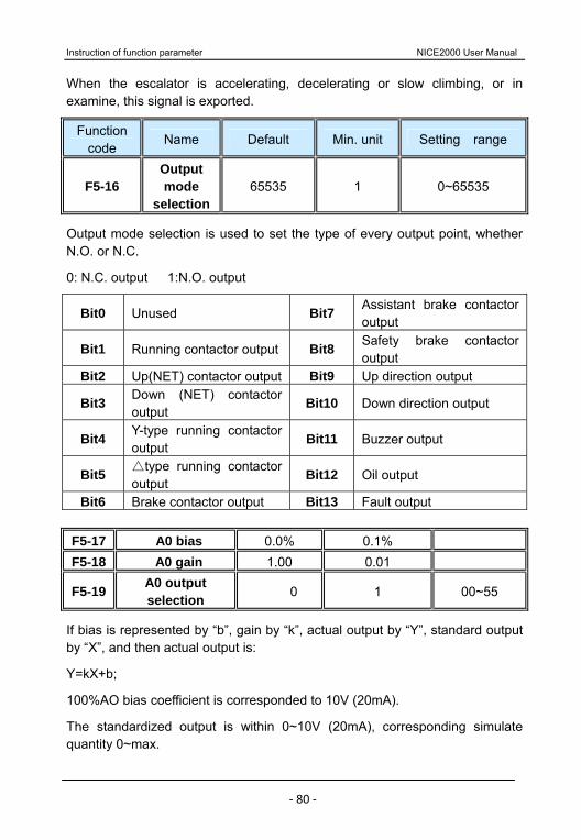
Instruction of function parameter NICE2000 User Manual
‐ 80 ‐
When the escalator is accelerating, decelerating or slow climbing, or in examine, this signal is exported.
Function code
Name Default Min. unit Setting range
F5-16 Output mode
selection65535 1 0~65535
Output mode selection is used to set the type of every output point, whether N.O. or N.C.
0: N.C. output 1:N.O. output
Bit0 Unused Bit7 Assistant brake contactor output
Bit1 Running contactor output Bit8 Safety brake contactor output
Bit2 Up(NET) contactor output Bit9 Up direction output
Bit3 Down (NET) contactor output
Bit10 Down direction output
Bit4 Y-type running contactor output
Bit11 Buzzer output
Bit5 type running contactor
output Bit12 Oil output
Bit6 Brake contactor output Bit13 Fault output F5-17 A0 bias 0.0% 0.1% F5-18 A0 gain 1.00 0.01
F5-19 A0 output selection 0 1 00~55
If bias is represented by “b”, gain by “k”, actual output by “Y”, standard output by “X”, and then actual output is:
Y=kX+b;
100%AO bias coefficient is corresponded to 10V (20mA).
The standardized output is within 0~10V (20mA), corresponding simulate quantity 0~max.
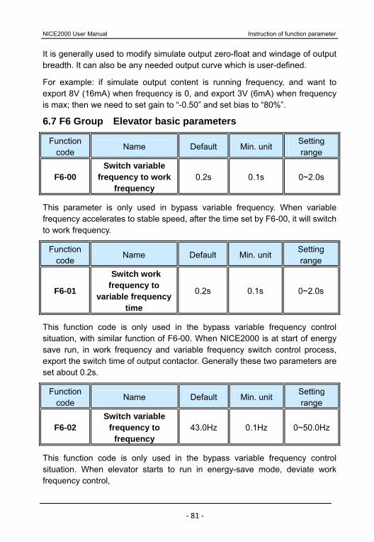
NICE2000 User Manual Instruction of function parameter
‐ 81 ‐
It is generally used to modify simulate output zero-float and windage of output breadth. It can also be any needed output curve which is user-defined.
For example: if simulate output content is running frequency, and want to export 8V (16mA) when frequency is 0, and export 3V (6mA) when frequency is max; then we need to set gain to “-0.50” and set bias to “80%”.
6.7 F6 Group Elevator basic parameters
Function code
Name Default Min. unit Setting range
F6-00 Switch variable
frequency to work frequency
0.2s 0.1s 0~2.0s
This parameter is only used in bypass variable frequency. When variable frequency accelerates to stable speed, after the time set by F6-00, it will switch to work frequency.
Function code
Name Default Min. unit Setting range
F6-01
Switch work frequency to
variable frequency time
0.2s 0.1s 0~2.0s
This function code is only used in the bypass variable frequency control situation, with similar function of F6-00. When NICE2000 is at start of energy save run, in work frequency and variable frequency switch control process, export the switch time of output contactor. Generally these two parameters are set about 0.2s.
Function code
Name Default Min. unit Setting range
F6-02 Switch variable
frequency to frequency
43.0Hz 0.1Hz 0~50.0Hz
This function code is only used in the bypass variable frequency control situation. When elevator starts to run in energy-save mode, deviate work frequency control,
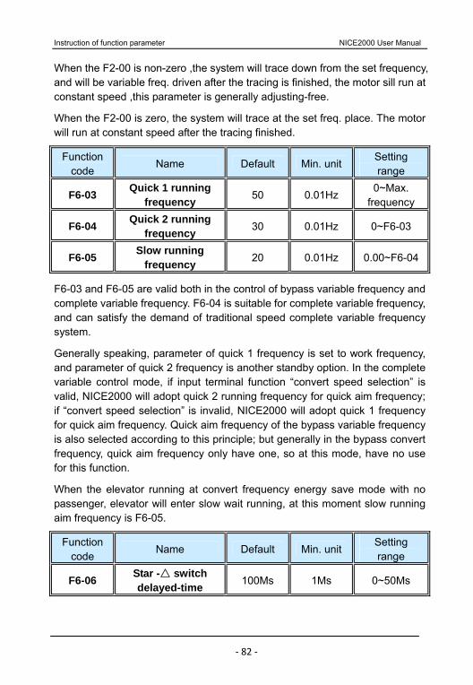
Instruction of function parameter NICE2000 User Manual
‐ 82 ‐
When the F2-00 is non-zero ,the system will trace down from the set frequency, and will be variable freq. driven after the tracing is finished, the motor sill run at constant speed ,this parameter is generally adjusting-free.
When the F2-00 is zero, the system will trace at the set freq. place. The motor will run at constant speed after the tracing finished.
Function code
Name Default Min. unitSetting range
F6-03 Quick 1 running frequency 50 0.01Hz
0~Max. frequency
F6-04 Quick 2 running frequency 30 0.01Hz 0~F6-03
F6-05 Slow running frequency 20 0.01Hz 0.00~F6-04
F6-03 and F6-05 are valid both in the control of bypass variable frequency and complete variable frequency. F6-04 is suitable for complete variable frequency, and can satisfy the demand of traditional speed complete variable frequency system.
Generally speaking, parameter of quick 1 frequency is set to work frequency, and parameter of quick 2 frequency is another standby option. In the complete variable control mode, if input terminal function “convert speed selection” is valid, NICE2000 will adopt quick 2 running frequency for quick aim frequency; if “convert speed selection” is invalid, NICE2000 will adopt quick 1 frequency for quick aim frequency. Quick aim frequency of the bypass variable frequency is also selected according to this principle; but generally in the bypass convert frequency, quick aim frequency only have one, so at this mode, have no use for this function.
When the elevator running at convert frequency energy save mode with no passenger, elevator will enter slow wait running, at this moment slow running aim frequency is F6-05.
Function code
Name Default Min. unitSetting range
F6-06 Star - switch
delayed-time 100Ms 1Ms 0~50Ms

NICE2000 User Manual Instruction of function parameter
‐ 83 ‐
When the controller is in star- mode, after FB -18 startup time, the star contactor is released, and then after F6-06 switching time, export contactor.
Function code
Name Default Min. unitSetting range
F6-07 Accelerate time 4.0s 0. 1s 0.0~3000.0sF6-08 Decelerate time 20.0s 0. 1s 0.0~3000.0s
Accelerate time is the time needed from zero speedup to Max. frequency Decelerate time is the time needed from Max . frequency decelerate to zero.
Refer to next fig 6-4:
Fig 6-4 Accelerate and decelerate time When set frequency equals to max.output frequency, actual accelerate/decelerate time is the given accelerate/decelerate time.
When set frequency is less than max. output frequency, actual accelerate time =set value×(set frequency /max.frequency).
Function code
Name Default Min. unitSetting range
F6-09 Inspection frequency 25.0Hz 0.01Hz
0~Max.frequency
F6-10 Inching (examine
and repair) accelerate time
20.0 0. 1s 0.0~3000.0s
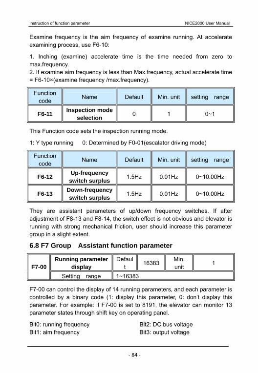
Instruction of function parameter NICE2000 User Manual
‐ 84 ‐
Examine frequency is the aim frequency of examine running. At accelerate examining process, use F6-10:
1. Inching (examine) accelerate time is the time needed from zero to max.frequency. 2. If examine aim frequency is less than Max.frequency, actual accelerate time = F6-10×(examine frequency /max.frequency).
Function code
Name Default Min. unit setting range
F6-11 Inspection mode selection 0 1 0~1
This Function code sets the inspection running mode.
1: Y type running 0: Determined by F0-01(escalator driving mode)
Function code
Name Default Min. unit setting range
F6-12 Up-frequency switch surplus 1.5Hz 0.01Hz 0~10.00Hz
F6-13 Down-frequency switch surplus 1.5Hz 0.01Hz 0~10.00Hz
They are assistant parameters of up/down frequency switches. If after adjustment of F8-13 and F8-14, the switch effect is not obvious and elevator is running with strong mechanical friction, user should increase this parameter group in a slight extent.
6.8 F7 Group Assistant function parameter
Running parameter display
Default
16383 Min. unit
1 F7-00 Setting range 1~16383
F7-00 can control the display of 14 running parameters, and each parameter is controlled by a binary code (1: display this parameter, 0: don’t display this parameter. For example: if F7-00 is set to 8191, the elevator can monitor 13 parameter states through shift key on operating panel.
Bit0: running frequency Bit1: aim frequency
Bit2: DC bus voltage Bit3: output voltage
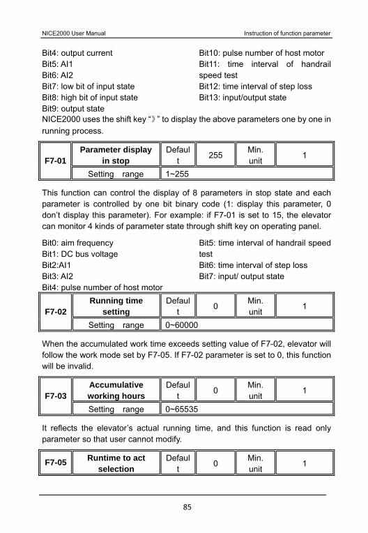
NICE2000 User Manual Instruction of function parameter
85
Bit4: output current Bit5: AI1 Bit6: AI2 Bit7: low bit of input state Bit8: high bit of input state Bit9: output state
Bit10: pulse number of host motor Bit11: time interval of handrail speed test Bit12: time interval of step loss Bit13: input/output state
NICE2000 uses the shift key “》” to display the above parameters one by one in running process.
Parameter display in stop
Default
255 Min. unit
1 F7-01 Setting range 1~255
This function can control the display of 8 parameters in stop state and each parameter is controlled by one bit binary code (1: display this parameter, 0 don’t display this parameter). For example: if F7-01 is set to 15, the elevator can monitor 4 kinds of parameter state through shift key on operating panel.
Bit0: aim frequency Bit1: DC bus voltage Bit2:AI1 Bit3: AI2 Bit4: pulse number of host motor
Bit5: time interval of handrail speed test Bit6: time interval of step loss Bit7: input/ output state
Running time setting
Default
0 Min. unit
1 F7-02 Setting range 0~60000
When the accumulated work time exceeds setting value of F7-02, elevator will follow the work mode set by F7-05. If F7-02 parameter is set to 0, this function will be invalid.
Accumulative working hours
Default
0 Min. unit
1 F7-03 Setting range 0~65535
It reflects the elevator’s actual running time, and this function is read only parameter so that user cannot modify.
F7-05 Runtime to act selection
Default
0 Min. unit
1
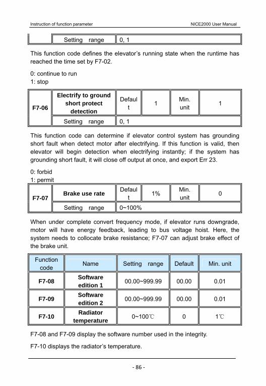
Instruction of function parameter NICE2000 User Manual
‐ 86 ‐
Setting range 0, 1
This function code defines the elevator’s running state when the runtime has reached the time set by F7-02.
0: continue to run 1: stop
Electrify to ground short protect
detection
Default
1 Min. unit
1 F7-06
Setting range 0, 1
This function code can determine if elevator control system has grounding short fault when detect motor after electrifying. If this function is valid, then elevator will begin detection when electrifying instantly; if the system has grounding short fault, it will close off output at once, and export Err 23.
0: forbid 1: permit
Brake use rate Default
1% Min. unit
0 F7-07
Setting range 0~100%
When under complete convert frequency mode, if elevator runs downgrade, motor will have energy feedback, leading to bus voltage hoist. Here, the system needs to collocate brake resistance; F7-07 can adjust brake effect of the brake unit.
Function code
Name Setting range Default Min. unit
F7-08 Software edition 1 00.00~999.99 00.00 0.01
F7-09 Software edition 2 00.00~999.99 00.00 0.01
F7-10 Radiator temperature 0~100 0 1
F7-08 and F7-09 display the software number used in the integrity.
F7-10 displays the radiator’s temperature.
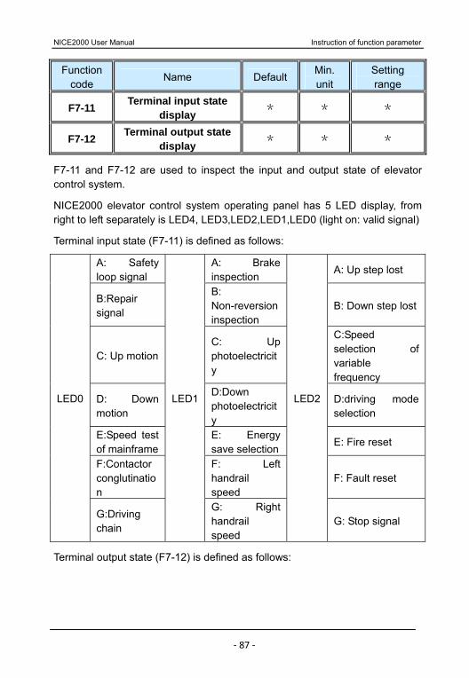
NICE2000 User Manual Instruction of function parameter
‐ 87 ‐
Function code
Name Default Min. unit
Setting range
F7-11 Terminal input state display
* * *
F7-12 Terminal output state display
* * *
F7-11 and F7-12 are used to inspect the input and output state of elevator control system.
NICE2000 elevator control system operating panel has 5 LED display, from right to left separately is LED4, LED3,LED2,LED1,LED0 (light on: valid signal)
Terminal input state (F7-11) is defined as follows:
A: Safety loop signal
A: Brake inspection
A: Up step lost
B:Repair signal
B: Non-reversion inspection
B: Down step lost
C: Up motionC: Up photoelectricity
C:Speed selection of variable frequency
D: Down motion
D:Down photoelectricity
D:driving mode selection
E:Speed test of mainframe
E: Energy save selection
E: Fire reset
F:Contactor conglutination
F: Left handrail speed
F: Fault reset
LED0
G:Driving chain
LED1
G: Right handrail speed
LED2
G: Stop signal
Terminal output state (F7-12) is defined as follows:
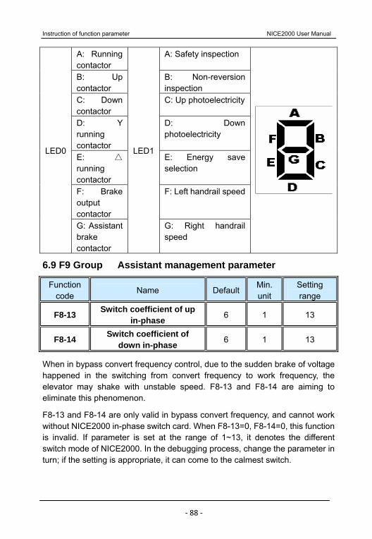
Instruction of function parameter NICE2000 User Manual
‐ 88 ‐
A: Running contactor
A: Safety inspection
B: Up contactor
B: Non-reversion inspection
C: Down contactor
C: Up photoelectricity
D: Y running contactor
D: Down photoelectricity
E:
running contactor
E: Energy save selection
F: Brake output contactor
F: Left handrail speed
LED0
G: Assistant brake contactor
LED1
G: Right handrail speed
6.9 F9 Group Assistant management parameter
Function code
Name Default Min. unit
Setting range
F8-13 Switch coefficient of up in-phase 6 1 13
F8-14 Switch coefficient of down in-phase 6 1 13
When in bypass convert frequency control, due to the sudden brake of voltage happened in the switching from convert frequency to work frequency, the elevator may shake with unstable speed. F8-13 and F8-14 are aiming to eliminate this phenomenon.
F8-13 and F8-14 are only valid in bypass convert frequency, and cannot work without NICE2000 in-phase switch card. When F8-13=0, F8-14=0, this function is invalid. If parameter is set at the range of 1~13, it denotes the different switch mode of NICE2000. In the debugging process, change the parameter in turn; if the setting is appropriate, it can come to the calmest switch.

NICE2000 User Manual Instruction of function parameter
‐ 89 ‐
Change to F6-00 parameter or periphery contactor act time will influence the setting of the F8-13 and F8-14, so the debugging process must conduct as: 1) first set F6-00=0; 2) debug F8-13 and F8-14, rectifying from large to small until feel the transition smoothly. If basically can feel the shake every time, minish F4-26 parameter (decrease 30 every time) until the shake is eliminated.
6.10 F9 Group Protection function parameter
Overload protect
selection Default 1 Min. unit 1 F9-00
Setting range 0, 1
0: The system has no over-load protection.
1: The system has over-load protection. Refer to F9-01.
Overload protect
coefficient Default 1.00 Min. unit 0.01
F9-01 Setting range
0.50~10.00
The reference of this function code is over-loaded current. When system has detected the output current reaching to F9-01×motor rated current and last to the end of anti-time limit curve fixed time, it will export Err 11.
F9-03 Over voltage lose speed gain 0 1
0(non over voltage lose
speed)~100
F9-04 Over voltage lose speed point 130% 1% 120~150%
F9-05 Over current lose speed gain 20 1 0~100
F9-06 Over current lose speed point 150% 1% 100~200%
Over voltage lose speed gain: It can adjust inverter’s ability to restrain over-voltage lose speed. The value of this parameter and the ability is in direct ratio.
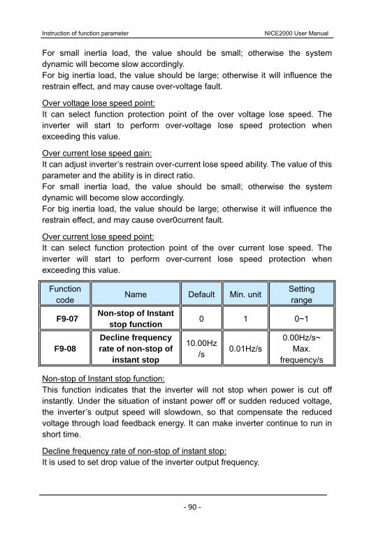
Instruction of function parameter NICE2000 User Manual
‐ 90 ‐
For small inertia load, the value should be small; otherwise the system dynamic will become slow accordingly. For big inertia load, the value should be large; otherwise it will influence the restrain effect, and may cause over-voltage fault.
Over voltage lose speed point: It can select function protection point of the over voltage lose speed. The inverter will start to perform over-voltage lose speed protection when exceeding this value.
Over current lose speed gain: It can adjust inverter’s restrain over-current lose speed ability. The value of this parameter and the ability is in direct ratio. For small inertia load, the value should be small; otherwise the system dynamic will become slow accordingly. For big inertia load, the value should be large; otherwise it will influence the restrain effect, and may cause over0current fault.
Over current lose speed point: It can select function protection point of the over current lose speed. The inverter will start to perform over-current lose speed protection when exceeding this value.
Function code
Name Default Min. unitSetting range
F9-07 Non-stop of Instant stop function 0 1 0~1
F9-08 Decline frequency rate of non-stop of
instant stop
10.00Hz/s
0.01Hz/s0.00Hz/s~
Max. frequency/s
Non-stop of Instant stop function: This function indicates that the inverter will not stop when power is cut off instantly. Under the situation of instant power off or sudden reduced voltage, the inverter’s output speed will slowdown, so that compensate the reduced voltage through load feedback energy. It can make inverter continue to run in short time.
Decline frequency rate of non-stop of instant stop: It is used to set drop value of the inverter output frequency.
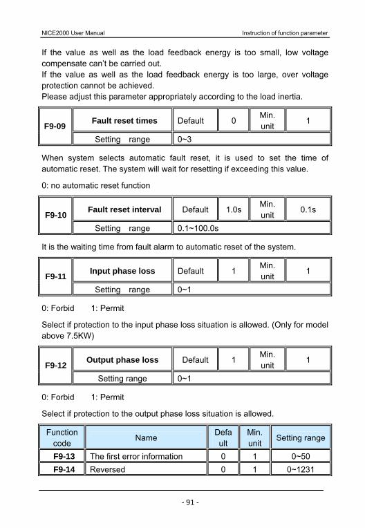
NICE2000 User Manual Instruction of function parameter
‐ 91 ‐
If the value as well as the load feedback energy is too small, low voltage compensate can’t be carried out. If the value as well as the load feedback energy is too large, over voltage protection cannot be achieved. Please adjust this parameter appropriately according to the load inertia.
Fault reset times Default 0 Min. unit
1 F9-09 Setting range 0~3
When system selects automatic fault reset, it is used to set the time of automatic reset. The system will wait for resetting if exceeding this value.
0: no automatic reset function
Fault reset interval Default 1.0sMin. unit
0.1s F9-10 Setting range 0.1~100.0s
It is the waiting time from fault alarm to automatic reset of the system.
Input phase loss Default 1 Min. unit
1 F9-11 Setting range 0~1
0: Forbid 1: Permit
Select if protection to the input phase loss situation is allowed. (Only for model above 7.5KW)
Output phase loss Default 1 Min. unit
1 F9-12 Setting range 0~1
0: Forbid 1: Permit
Select if protection to the output phase loss situation is allowed.
Function code
Name Default
Min. unit
Setting range
F9-13 The first error information 0 1 0~50 F9-14 Reversed 0 1 0~1231
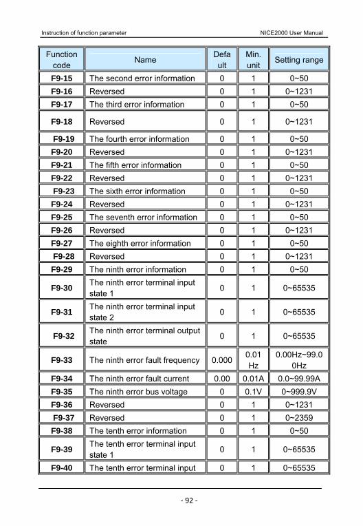
Instruction of function parameter NICE2000 User Manual
‐ 92 ‐
Function code
Name Default
Min. unit
Setting range
F9-15 The second error information 0 1 0~50 F9-16 Reversed 0 1 0~1231 F9-17 The third error information 0 1 0~50
F9-18 Reversed 0 1 0~1231
F9-19 The fourth error information 0 1 0~50 F9-20 Reversed 0 1 0~1231 F9-21 The fifth error information 0 1 0~50 F9-22 Reversed 0 1 0~1231 F9-23 The sixth error information 0 1 0~50 F9-24 Reversed 0 1 0~1231 F9-25 The seventh error information 0 1 0~50 F9-26 Reversed 0 1 0~1231 F9-27 The eighth error information 0 1 0~50 F9-28 Reversed 0 1 0~1231 F9-29 The ninth error information 0 1 0~50
F9-30 The ninth error terminal input state 1
0 1 0~65535
F9-31 The ninth error terminal input state 2
0 1 0~65535
F9-32 The ninth error terminal output state
0 1 0~65535
F9-33 The ninth error fault frequency 0.0000.01Hz
0.00Hz~99.00Hz
F9-34 The ninth error fault current 0.00 0.01A 0.0~99.99AF9-35 The ninth error bus voltage 0 0.1V 0~999.9V F9-36 Reversed 0 1 0~1231 F9-37 Reversed 0 1 0~2359 F9-38 The tenth error information 0 1 0~50
F9-39 The tenth error terminal input state 1 0 1 0~65535
F9-40 The tenth error terminal input 0 1 0~65535

NICE2000 User Manual Instruction of function parameter
‐ 93 ‐
Function code
Name Default
Min. unit
Setting range
state 2
F9-41 The tenth error terminal output state
0 1 0~65535
F9-42 The tenth error fault frequency 0.0000.01Hz
0.00Hz~99.00Hz
F9-43 The tenth error fault current 0.0 0.01A 0.0~99.99AF9-44 The tenth error bus voltage 0 0.1V 0~999.9V F9-45 Reversed 0 1 0~1231 F9-46 Reversed 0 1 0~2359 F9-47 The last error information 0 1 0~50
F9-48 The last error terminal input state 1
0 1 0~65535
F9-49 The last error terminal input state 2
0 1 0~65535
F9-50 The last error terminal output state
0 1 0~65535
F9-51 Last error fault frequency 0.0000.01Hz
0.00Hz~99.00Hz
F9-52 The last error fault current 0.00 0.01A 0.0~99.99AF9-53 Error bus voltage 0 0.1V 0~999.9V F9-54 Reversed 0 1 0~1231 F9-55 Reversed 0 1 0~2359
This group parameter can record the latest 11 fault information and fault occurring time. Fault information displays fault code. As to the detailed type and their significations, please refer to chapter 8.
6.11 FA Group Communication parameter Refer to 《NICE2000 Communication Protocol》
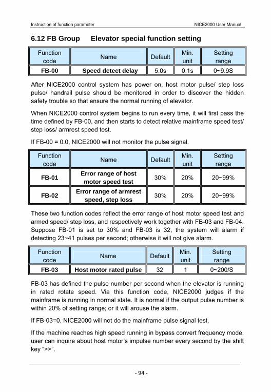
Instruction of function parameter NICE2000 User Manual
‐ 94 ‐
6.12 FB Group Elevator special function setting
Function code
Name DefaultMin. unit
Setting range
FB-00 Speed detect delay 5.0s 0.1s 0~9.9S
After NICE2000 control system has power on, host motor pulse/ step loss pulse/ handrail pulse should be monitored in order to discover the hidden safety trouble so that ensure the normal running of elevator.
When NICE2000 control system begins to run every time, it will first pass the time defined by FB-00, and then starts to detect relative mainframe speed test/ step loss/ armrest speed test.
If FB-00 = 0.0, NICE2000 will not monitor the pulse signal.
Function code
Name DefaultMin. unit
Setting range
FB-01 Error range of host motor speed test 30% 20% 20~99%
FB-02 Error range of armrest speed, step loss 30% 20% 20~99%
These two function codes reflect the error range of host motor speed test and armed speed/ step loss, and respectively work together with FB-03 and FB-04. Suppose FB-01 is set to 30% and FB-03 is 32, the system will alarm if detecting 23~41 pulses per second; otherwise it will not give alarm.
Function code
Name DefaultMin. unit
Setting range
FB-03 Host motor rated pulse 32 1 0~200/S
FB-03 has defined the pulse number per second when the elevator is running in rated rotate speed. Via this function code, NICE2000 judges if the mainframe is running in normal state. It is normal if the output pulse number is within 20% of setting range; or it will arouse the alarm.
If FB-03=0, NICE2000 will not do the mainframe pulse signal test.
If the machine reaches high speed running in bypass convert frequency mode, user can inquire about host motor’s impulse number every second by the shift key “>>”.
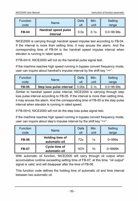
NICE2000 User Manual Instruction of function parameter
‐ 95 ‐
Function code
Name Default
Min. unit
Setting range
FB-04 Handrail speed pulse interval 0.0s 0.1s 0.0~99.99s
NICE2000 is carrying though handrail speed impulse test according to FB-04. If the interval is more than setting time, it may arouse the alarm. And the corresponding time of FB-04 is the handrail speed impulse interval when elevator is running in rated speed.
If FB-04=0, NICE2000 will not do the handrail pulse signal test.
If the machine reaches high speed running in bypass convert frequency mode, user can inquire about handrail’s impulse interval by the shift key “>>”.
Function code
Name Default
Min. unit
Setting range
FB-05 Step lose pulse interval 0.00s 0.1s 0.0~99.99s Similar to handrail speed pulse interval, NICE2000 is carrying through step loss pulse interval according to FB-05. If the interval is more than setting time, it may arouse the alarm. And the corresponding time of FB-05 is the step pulse interval when elevator is running in rated speed.
If FB-05=0, NICE2000 will not do the step loss pulse signal test.
If the machine reaches high speed running in bypass convert frequency mode, user can inquire about step’s impulse interval by the shift key “>>”.
Function code
Name Default
Min. unit
Setting range
FB-06 Holding time of automatic-oil 72s 1s 0~999s
FB-07 Cycle time of automatic-oil 167h 1h 0~9999h
With automatic oil function, NICE2000 will carry through oil output when accumulative runtime exceeding setting time of FB-07; at this time, “oil output” signal is valid, and will disappear after the time of FB-06.
This function code defines the holding time of automatic oil and time interval between two automatic oil.
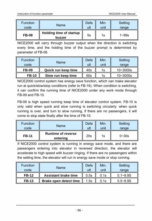
Instruction of function parameter NICE2000 User Manual
‐ 96 ‐
Function code
Name Default
Min. unit
Setting range
FB-08 Holding time of startup buzzer 5s 1s 1~99s
NICE2000 will carry through buzzer output when the direction is switching every time, and the holding time of the buzzer prompt is determined by parameter of FB-08.
Function code
Name Default
Min. unit
Setting range
FB-09 Quick run keep time 40s 1s 10~3000s FB-10 Slow run keep time 60s 1s 10~3000s
NICE2000 control system has energy save function, which can make elevator run at quick/slow/stop conditions (refer to FB-16). When condition is switching, it can confirm the running time of NICE2000 under any work mode through FB-09 and FB-10.
FB-09 is high speed running keep time of elevator control system. FB-10 is only valid when quick and slow running is switching circularly: when quick running is over, and turn to slow running, if there are no passengers, it will come to stop state finally after the time of FB-10.
Function code
Name Default
Min. unit
Setting range
FB-11 Runtime of reverse entering 20s 1s 0~30s
If NICE2000 control system is running in energy save mode, and there are passengers entering into elevator in reversed direction, the elevator will accelerate to high speed with buzzer ringing. If there are no passengers within the setting time, the elevator will run in energy save mode or stop running.
Function code
Name Default
Min. unit
Setting range
FB-12 Assistant brake time 0.5s 0.1s 0.1~9.9S FB-13 Brake open detect time 1.5s 0.1s 0.5~9.9S
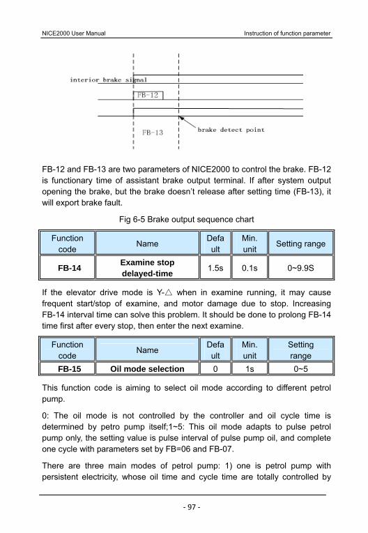
NICE2000 User Manual Instruction of function parameter
‐ 97 ‐
FB-12 and FB-13 are two parameters of NICE2000 to control the brake. FB-12 is functionary time of assistant brake output terminal. If after system output opening the brake, but the brake doesn’t release after setting time (FB-13), it will export brake fault.
Fig 6-5 Brake output sequence chart
Function code
Name Default
Min. unit
Setting range
FB-14 Examine stop delayed-time 1.5s 0.1s 0~9.9S
If the elevator drive mode is Y- when in examine running, it may cause
frequent start/stop of examine, and motor damage due to stop. Increasing FB-14 interval time can solve this problem. It should be done to prolong FB-14 time first after every stop, then enter the next examine.
Function code
Name Default
Min. unit
Setting range
FB-15 Oil mode selection 0 1s 0~5
This function code is aiming to select oil mode according to different petrol pump.
0: The oil mode is not controlled by the controller and oil cycle time is determined by petro pump itself;1~5: This oil mode adapts to pulse petrol pump only, the setting value is pulse interval of pulse pump oil, and complete one cycle with parameters set by FB=06 and FB-07.
There are three main modes of petrol pump: 1) one is petrol pump with persistent electricity, whose oil time and cycle time are totally controlled by
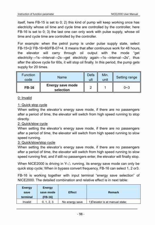
Instruction of function parameter NICE2000 User Manual
‐ 98 ‐
itself, here FB-15 is set to 0; 2) this kind of pump will keep working once has electricity whose oil time and cycle time are controlled by the controller, here FB-16 is set to 0; 3) the last one can only work with pulse supply, whose oil time and cycle time are controlled by the controller.
For example: when the petrol pump is under pulse supply state, select FB-15=2/ FB-16=60/FB-07=4. It means that after continuous work for 48 hours, the elevator will carry through oil output with the mode “get electricity→1s→interval→2s→get electricity again→1s→interval→2s”, thus after the above cycle for 60s, it will stop oil finally. In this period, the pump gets supply for 20 times.
Function code
Name Default
Min. unit
Setting range
FB-16 Energy save mode selection 2 1 0~3
0: Invalid
1: Quick stop cycle When setting the elevator’s energy save mode, if there are no passengers after a period of time, the elevator will switch from high speed running to stop directly. 2: Quick/slow cycle When setting the elevator’s energy save mode, if there are no passengers after a period of time, the elevator will switch from high speed running to slow speed running. 3: Quick/slow/stop cycle When setting the elevator’s energy save mode, if there are no passengers after a period of time, the elevator will switch from high speed running to slow speed running first, and if still no passengers enter, the elevator will finally stop.
When NICE2000 is driving in Y- running, its energy save mode can only be
quick stop cycle; When in bypass convert frequency, FB-16 can select 1, 2 or3.
FB-16 is working together with input terminal “energy save selection” of NICE2000. The detailed combination and relative effect is in next table:
Energy save
terminal
Energy save mode
(FB-16) Effect Remark
Invalid 0, 1, 2, 3 No energy save 1)Elevator is at manual state;

NICE2000 User Manual Instruction of function parameter
‐ 99 ‐
Energy save
terminal
Energy save mode
(FB-16) Effect Remark
effect 2)Running direction is determined by terminal “up” and “down”; 3)Keep high speed running after startup;
Avail 0 No energy save
effect
1)Elevator is at automatic state; 2)Running direction is determined by terminal “up” and “down”; 3) Keep high speed running after startup;
Avail 1 Quick/stop cycle
energy save
1)Elevator is at automatic state; 2)When FB-17=0, running direction is determined by terminal “up” and “down”; 3)When FB-17=1, running direction is determined by terminal “up photoelectricity” and “down photoelectricity”; 4)When elevator is in quick and stop state conversion, the corresponding state keep time is determined by quick keep time(FB-09)
Avail 2 Quick/slow cycle
energy save
1)Elevator is at automatic state; 2)When FB-17=0, running direction is determined by terminal “up” and “down”; 3)When FB-17=1, running direction is determined by terminal “up photoelectricity” and “down photoelectricity”; but under this mode elevator will not stop, so the direction will not change; 4)When elevator is in quick and slow state conversion, the corresponding state keep time is determined by quick keep time( FB-09) and slow keep time (FB-10);
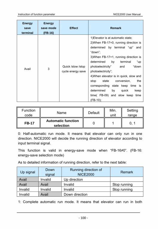
Instruction of function parameter NICE2000 User Manual
‐ 100 ‐
Energy save
terminal
Energy save mode
(FB-16) Effect Remark
Avail 3 Quick /slow /stop cycle energy save
1)Elevator is at automatic state; 2)When FB-17=0, running direction is determined by terminal “up” and “down”; 3)When FB-17=1, running direction is determined by terminal “up photoelectricity” and “down photoelectricity”; 4)When elevator is in quick, slow and stop state conversion, the corresponding state keep time is determined by quick keep time( FB-09) and slow keep time (FB-10);
Function
code Name Default
Min. unit
Setting range
FB-17 Automatic function selection 0 1 0, 1
0: Half-automatic run mode. It means that elevator can only run in one direction. NICE2000 will decide the running direction of elevator according to input terminal signal.
This function is valid in energy-save mode when “FB-16≠0”. (FB-16: energy-save selection mode)
As to detailed information of running direction, refer to the next table:
Up signal Down signal
Running direction of NICE2000
Remark
Avail Invalid Up direction Avail Avail Invalid Stop running Invalid Invalid Invalid Stop running Invalid Avail Down direction
1: Complete automatic run mode. It means that elevator can run in both
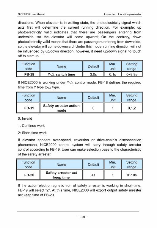
NICE2000 User Manual Instruction of function parameter
‐ 101 ‐
directions. When elevator is in waiting state, the photoelectricity signal which acts first will determine the current running direction. For example: up photoelectricity valid indicates that there are passengers entering from underside, so the elevator will come upward; On the contrary, down photoelectricity valid means that there are passengers entering from downside, so the elevator will come downward. Under this mode, running direction will not be influenced by up/down direction, however, it need up/down signal to touch off to start up.
Function code
Name Default Min. unit
Setting range
FB-18 Y- switch time 3.0s 0.1s 0~9.9s
If NICE2000 is working under Y- control mode, FB -18 defines the required time from Y type to type.
Function code
Name Default Min. unit
Setting range
FB-19 Safety arrester action mode 0 1 0,1,2
0: Invalid
1: Continue work
2: Short time work
If elevator appears over-speed, reversion or drive-chain’s disconnection phenomena, NICE2000 control system will carry through safety arrester control according to FB-19. User can make selection base to the characteristic of the safety arrester.
Function code
Name Default Min. unit
Setting range
FB-20 Safety arrester act keep time 4s 1 0~10s
If the action electromagnetic iron of safety arrester is working in short-time, FB-19 will select “2”. At this time, NICE2000 will export output safety arrester act keep time of FB-20.
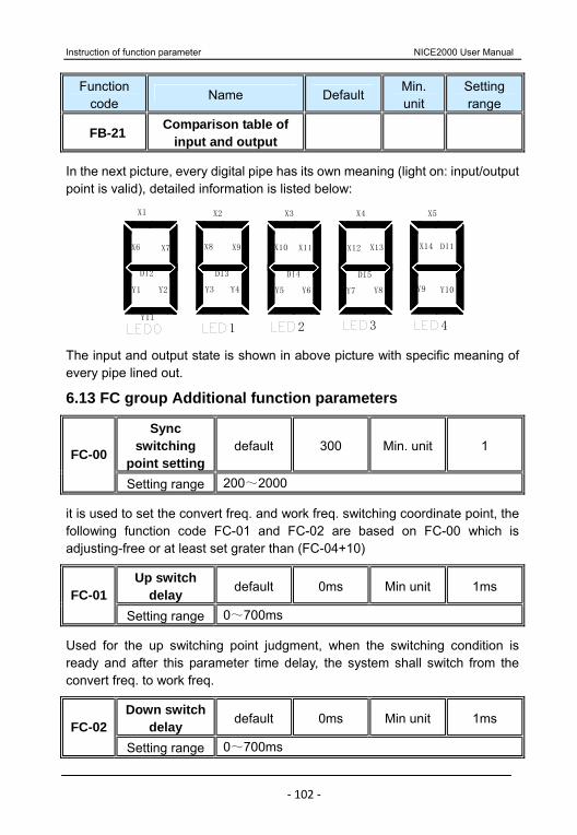
Instruction of function parameter NICE2000 User Manual
‐ 102 ‐
Function code
Name Default Min. unit
Setting range
FB-21 Comparison table of input and output
In the next picture, every digital pipe has its own meaning (light on: input/output point is valid), detailed information is listed below:
1
X2
DI3
Y11
DI2
Y1 Y2
X6 X7
Y3
X8
X1
2
X11
Y4
X9
Y5
DI4
X10
3
Y6
DI5
Y7 Y8
X12 X13
4
X14
Y9 Y10
DI1
X3 X4 X5
The input and output state is shown in above picture with specific meaning of every pipe lined out.
6.13 FC group Additional function parameters
Sync switching
point settingdefault 300 Min. unit 1 FC-00
Setting range 200~2000
it is used to set the convert freq. and work freq. switching coordinate point, the following function code FC-01 and FC-02 are based on FC-00 which is adjusting-free or at least set grater than (FC-04+10)
Up switch delay default 0ms Min unit 1ms FC-01
Setting range 0~700ms
Used for the up switching point judgment, when the switching condition is ready and after this parameter time delay, the system shall switch from the convert freq. to work freq.
Down switch delay default 0ms Min unit 1ms FC-02
Setting range 0~700ms
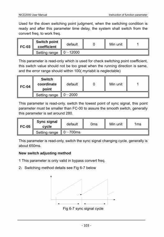
NICE2000 User Manual Instruction of function parameter
‐ 103 ‐
Used for the down switching point judgment, when the switching condition is ready and after this parameter time delay, the system shall switch from the convert freq. to work freq.
Switch point coefficient default 0 Min unit 1 FC-03
Setting range 0~12000
This parameter is read-only which is used for check switching point coefficient, this switch value should not be too great when the running direction is same, and the error range should within 100( myriabit is neglectable)
Switch coordinate
point default 0 Min unit 1 FC-04
Setting range 0~2000
This parameter is read-only, switch the lowest point of sync signal, this point parameter must be smaller than FC-00 to assure the smooth switch, generally this parameter is set around 280.
Sync signal cycle default 0ms Min unit 1ms FC-05
Setting range 0~700ms
This parameter is read-only, switch the sync signal changing cycle, generally is about 650ms.
New switch adjusting method
1 This parameter is only valid in bypass convert freq.
2:Switching method details see Fig 6-7 below
Fig 6-7 sync signal cycle

Instruction of function parameter NICE2000 User Manual
‐ 104 ‐
3 Firstly, choosing FC-01 or FC-02 for adjusting on the basis of running direction. Starting adjusting from 0 and add 100 each time ( 0, 100, 200, 300, 400, 500, 600 respectively) then select the best one. After this, done the fine tuning by add or reduce 20 to select the most appropriate parameter.
4 Judging the correctness of FC-03, FC-04, FC-05 ( set the change of FC-03 at the same direction as criteria – changing range should smaller than 100). FC-04 should smaller than 300, FC-05 should around 650.
5 Please check F4-29, F4-30, F6-12, F6-13 or sync card wiring and sync card condition for FC-03, FC-04, FC-05 abnormal.
6.14 FF Group Factory parameter (reserved) 6.15 FP Group User parameter
Function code
Name Default Min. unit
Setting range
FP-00 User password 0 1 0~65535
Set it as any number except zero so that the password protection function is valid.
00000: eliminate the former user’s password value and make password protect function invalid.
When user password is set and become effective, NICE2000 will forbid examining the parameter.
Please fix your password. If mis-setting or forget, please contact with factory.
Function code
Name Default Min. unit
Setting range
FP-01 Parameter update 0 1 0,1,2
0: No operation.
1: Inverter will resume all the parameters to factory default. 2: Inverter will eliminate the latest fault record.
Function code
Name Default Min. unit
Setting range
FP-02 User setting examine 0 1 0,1
NICE2000 User Manual Instruction of function parameter
‐ 105 ‐
After having selected FP-02 function, operating panel LED only display the parameter which is different from default in order to make it convenient for user to check up the setting and discover problems.

Instruction of function parameter NICE2000 User Manual
‐ 106 ‐
NICE2000 User Manual Instruction of function parameter
‐ 107 ‐
Typical application and adjusting of system
Typical application and adjusting of system NICE2000 User Manual
‐ 108 ‐
Chapter 7 Typical application and adjusting of system
7.1 Typical application of bypass variable frequency
Escalator bypass variable frequency technique is the combination of variable frequency drive and work frequency drive. The predominance of convert frequency drive is when startup and wait state, motor will shift smoothly with small current concussion, so that when there are few passengers, the escalator will running at slow speed. It not only can save energy but also can reduce mechanical abrasion. The advantage of direct electricity drive is calm speed running process, which use the simplest mode to achieve energy feedback without brake resistance. So bypass variable frequency is that take advantage of variable frequency drive into the variable speed process. If switch the drive motor to work frequency and prepare to enter rated speed running, inverter bypass will wait. In this process, inverter work for a short time so that save the system cost.
NICE2000 provides a suit of traditional Y-- standby control system besides
bypass variable frequency control. With these two systems, it can reduce fault at largest extent.
NICE 2000 has combined the escalator controller and inverter together, providing user a special resolvent. It not only can make full use of variable frequency and work frequency, but also can eliminate the brake energy save resistance. Energy save, low equipment cost and compact structure, all of these advantages are definitely the future trend of escalator development.
7.1.1 connection mode
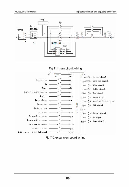
NICE2000 User Manual Typical application and adjusting of system
‐ 109 ‐
Fig 7.1 main circuit wiring
Fig 7-2 expansion board wiring
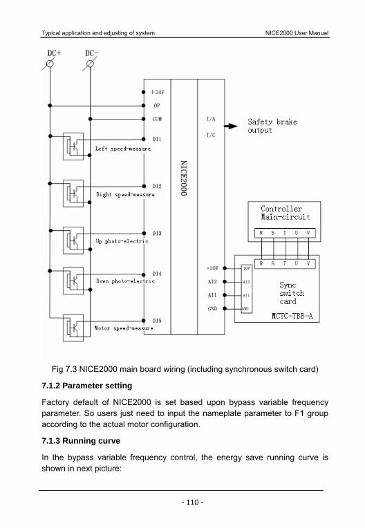
Typical application and adjusting of system NICE2000 User Manual
‐ 110 ‐
Fig 7.3 NICE2000 main board wiring (including synchronous switch card)
7.1.2 Parameter setting
Factory default of NICE2000 is set based upon bypass variable frequency parameter. So users just need to input the nameplate parameter to F1 group according to the actual motor configuration.
7.1.3 Running curve
In the bypass variable frequency control, the energy save running curve is shown in next picture:
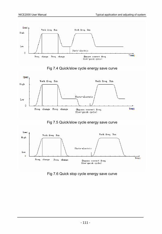
NICE2000 User Manual Typical application and adjusting of system
‐ 111 ‐
Fig 7.4 Quick/slow cycle energy save curve
Fig 7.5 Quick/slow cycle energy save curve
Fig 7.6 Quick stop cycle energy save curve
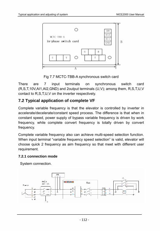
Typical application and adjusting of system NICE2000 User Manual
‐ 112 ‐
Fig 7.7 MCTC-TBB-A synchronous switch card
There are 7 input terminals on synchronous switch card (R,S,T,10V,AI1,AI2,GND) and 2output terminals (U,V); among them, R,S,T,U,V contact to R,S,T,U,V on the inverter respectively.
7.2 Typical application of complete VF
Complete variable frequency is that the elevator is controlled by inverter in accelerate/decelerate/constant speed process. The difference is that when in constant speed, power supply of bypass variable frequency is driven by work frequency, while complete convert frequency is totally driven by convert frequency.
Complete variable frequency also can achieve multi-speed selection function. When input terminal “variable frequency speed selection” is valid, elevator will choose quick 2 frequency as aim frequency so that meet with different user requirement.
7.2.1 connection mode
System connection.
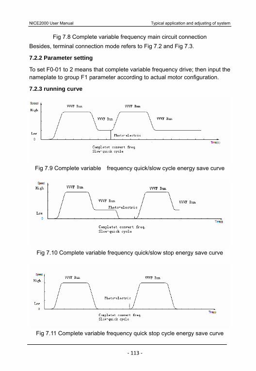
NICE2000 User Manual Typical application and adjusting of system
‐ 113 ‐
Fig 7.8 Complete variable frequency main circuit connection Besides, terminal connection mode refers to Fig 7.2 and Fig 7.3.
7.2.2 Parameter setting
To set F0-01 to 2 means that complete variable frequency drive; then input the nameplate to group F1 parameter according to actual motor configuration.
7.2.3 running curve
Fig 7.9 Complete variable frequency quick/slow cycle energy save curve
Fig 7.10 Complete variable frequency quick/slow stop energy save curve
Fig 7.11 Complete variable frequency quick stop cycle energy save curve
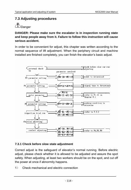
Typical application and adjusting of system NICE2000 User Manual
‐ 114 ‐
7.3 Adjusting procedures
Danger
DANGER: Please make sure the escalator is in inspection running state and keep people away from it. Failure to follow this instruction will cause serious accident.
In order to be convenient for adjust, this chapter was written according to the normal sequence of lift adjustment. When the periphery circuit and machine installed are finished completely, you can finish the elevator’s basic adjust.
7.3.1 Check before slow state adjustment
Correct adjust is the safeguard of elevator’s normal running. Before electric adjust, please check whether it is allowed to be adjusted and assure the spot safety. When adjusting, at least two workers should be on the spot, and cut off the power at once if abnormity happens.
1) Check mechanical and electric connection
NICE2000 User Manual Typical application and adjusting of system
‐ 115 ‐
Check periphery before electrify, in order to ensure human safety.
a) Suitable component type.
b) Well connected safe circuit.
c) No person in elevator, and safe running condition.
d) Well grounded.
e) Correct periphery connection according to factory drawing.
f) Credible switch.
g) Check resistance between phases of main circuit, and judge whether connected to the earth.
h) Confirm that the elevator is in inspection state.
i) make sure that machine is installed correctly, and it will not damage to human and equipment.
2) Power check
It is necessary to check the power before electrify.
a) The voltage between every two phases of user power should within the range of 380V±15%, and imbalance range of each phase should be no more than 3%.
b) The input voltage of interface terminal between DC+ and DC- is DC 24V.
Note: It will cause devastating result if the input voltage is over the allowed value; please check carefully. Please confirm positive and negative polarity of DC. Don’t move the car if the system input power is in phase failure state.
3) Grounding check
Please check the electricity supply before the system is power on.
a) Find out whether the resistance between grounding terminal and PE is infinite, if it is too small, check immediately.
Between R, S, T and PE
Between U1, V1, W1 and PE
Between motor U21, V21, W21, U22, V22, W22 and PE
Typical application and adjusting of system NICE2000 User Manual
‐ 116 ‐
Between mainboard 24V and PE
Between terminal of safe circuit, inspection circuit and PE
b) Find out whether the resistance between grounding terminal of all the electric part and power input PE is infinite, if it is too small, check immediately.
7.3.2 Adjustment
After checking the periphery, take off brake control wire, and turn the electricity on. Observe whether have output or not in the state of un-running; even if brake control wire is connected, brake can’t be open as well, then cut off the power, and connect brake control wire. Prepare run at low speed.
1. Check after power-on
1) Make sure the input voltage (on main board) between CN2 +24V and COM is within range DC24V±0.5V.
2) Make sure the voltage between DC+ and DC- terminal CN1 is 24V.
2. Setting function of terminal parameters check
Terminal function parameter group F4 and F5 will decide whether the received signal is correspondent with signal sent by system, and whether the expected aim is same with real aim.
1) Check whether the function of each setting terminal right according to the factory chart, and whether input/output terminal type is complied with the actual type.
2) Check out the corresponding input terminal signal is normal or not, through the numeral pipe on/off LED and input/output setting type of the corresponding terminal.
3. Motor tuning
Choose the keyboard running mode. Before motor tuning, please input parameter F1-00~F1-05; NICE2000 controller match standard based upon this nameplate.
4. Check test running
After above preparation, we can carry through test-run, and the inspection speed is set by F6-09 (default: 25Hz);

NICE2000 User Manual Typical application and adjusting of system
‐ 117 ‐
1) Input signal check
Check carefully whether the action sequence of the switch signals received is correct or not.( safety dot input signal, examine up/down input signal, touch conglutination signal, pre-reversion signal, brake opening signal etc.)
2) Output signal check
Check carefully whether the definition of MCB output terminal is corresponding to the relative contactor and whether the signal and the contact controlled by MCB output terminal work well. (Running contactor, brake contactor etc.)
3) Running direction check
Observe whether the actual direction is same with the aim direction (direction sign of motor flywheel is significant judgment); if not, please change two phases of motor randomly.
4) Sensor check
Main motor test speed sensor, left right speed sensor, up down step loss sensor are important guarantee for the normal running. If the running speed is abnormal, after sensor detecting abnormity signal, it will automatically cut off the running of the elevator. Observe carefully if sensor power light is normal or not, or survey if signal output terminal have voltage or not.
5. Check before high speed
On the basis of examine running, renew the escalator to normal state, and test running circs at hand and auto state separately, examine item by item according to the parameter setting.
Typical application and adjusting of system NICE2000 User Manual
‐ 118 ‐

NICE2000 User Manual Typical application and adjusting of system
‐ 119 ‐
Fault Diagnosis and Countermeasures
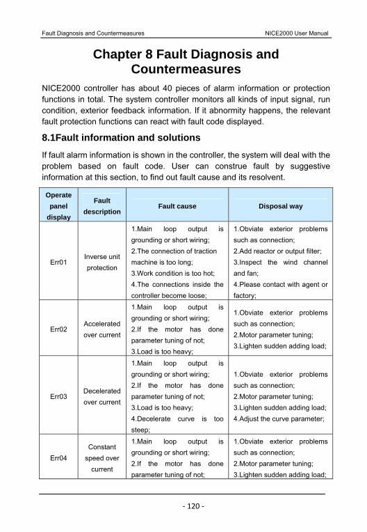
Fault Diagnosis and Countermeasures NICE2000 User Manual
‐ 120 ‐
Chapter 8 Fault Diagnosis and Countermeasures
NICE2000 controller has about 40 pieces of alarm information or protection functions in total. The system controller monitors all kinds of input signal, run condition, exterior feedback information. If it abnormity happens, the relevant fault protection functions can react with fault code displayed.
8.1Fault information and solutions
If fault alarm information is shown in the controller, the system will deal with the problem based on fault code. User can construe fault by suggestive information at this section, to find out fault cause and its resolvent.
Operate panel
display
Fault description
Fault cause Disposal way
Err01 Inverse unit protection
1.Main loop output is grounding or short wiring; 2.The connection of traction machine is too long; 3.Work condition is too hot; 4.The connections inside the controller become loose;
1.Obviate exterior problems such as connection; 2.Add reactor or output filter; 3.Inspect the wind channel and fan; 4.Please contact with agent or factory;
Err02 Accelerated over current
1.Main loop output is grounding or short wiring; 2.If the motor has done parameter tuning of not; 3.Load is too heavy;
1.Obviate exterior problems such as connection; 2.Motor parameter tuning; 3.Lighten sudden adding load;
Err03 Decelerated over current
1.Main loop output is grounding or short wiring; 2.If the motor has done parameter tuning of not; 3.Load is too heavy; 4.Decelerate curve is too steep;
1.Obviate exterior problems such as connection; 2.Motor parameter tuning; 3.Lighten sudden adding load;4.Adjust the curve parameter;
Err04 Constant
speed over current
1.Main loop output is grounding or short wiring; 2.If the motor has done parameter tuning of not;
1.Obviate exterior problems such as connection; 2.Motor parameter tuning; 3.Lighten sudden adding load;
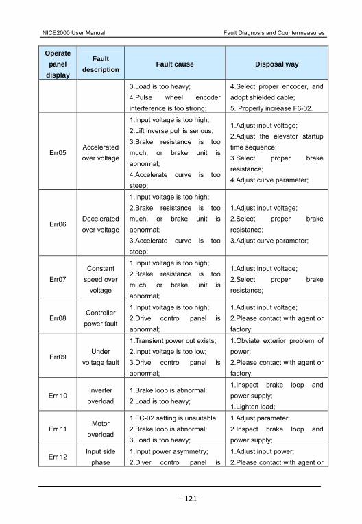
NICE2000 User Manual Fault Diagnosis and Countermeasures
‐ 121 ‐
Operate panel
display
Fault description
Fault cause Disposal way
3.Load is too heavy; 4.Pulse wheel encoder interference is too strong;
4.Select proper encoder, and adopt shielded cable; 5. Properly increase F6-02.
Err05 Accelerated over voltage
1.Input voltage is too high; 2.Lift inverse pull is serious; 3.Brake resistance is too much, or brake unit is abnormal; 4.Accelerate curve is too steep;
1.Adjust input voltage; 2.Adjust the elevator startup time sequence; 3.Select proper brake resistance; 4.Adjust curve parameter;
Err06 Decelerated over voltage
1.Input voltage is too high; 2.Brake resistance is too much, or brake unit is abnormal; 3.Accelerate curve is too steep;
1.Adjust input voltage; 2.Select proper brake resistance; 3.Adjust curve parameter;
Err07 Constant
speed over voltage
1.Input voltage is too high; 2.Brake resistance is too much, or brake unit is abnormal;
1.Adjust input voltage; 2.Select proper brake resistance;
Err08 Controller power fault
1.Input voltage is too high; 2.Drive control panel is abnormal;
1.Adjust input voltage; 2.Please contact with agent or factory;
Err09 Under
voltage fault
1.Transient power cut exists; 2.Input voltage is too low; 3.Drive control panel is abnormal;
1.Obviate exterior problem of power; 2.Please contact with agent or factory;
Err 10 Inverter overload
1.Brake loop is abnormal; 2.Load is too heavy;
1.Inspect brake loop and power supply; 1.Lighten load;
Err 11 Motor
overload
1.FC-02 setting is unsuitable; 2.Brake loop is abnormal; 3.Load is too heavy;
1.Adjust parameter; 2.Inspect brake loop and power supply;
Err 12 Input side
phase 1.Input power asymmetry; 2.Diver control panel is
1.Adjust input power; 2.Please contact with agent or

Fault Diagnosis and Countermeasures NICE2000 User Manual
‐ 122 ‐
Operate panel
display
Fault description
Fault cause Disposal way
failure abnormal; factory;
Err 13 Output side
phase failure
1.The connections of main loop output become loose; 2.Motor is broken;
1.Inspect connection; 2.Obviate motor fault;
Err 14 Module
overheated
1.The temperature of working environment is too high; 2.The fan is broken; 3.The wind channel is blocked;
1.Reduce the environmental temperature; 2.Clear the wind channel; 3.Change the fan;
Err 15 Reserved
Err 16 Reserved
Err 17 Contactor
fault
1.Bus voltage is abnormal; 2.Drive control panel is abnormal;
Please contact with agent or factory;
Err 18 Current
detection fault
Diver control panel is abnormal;
Please contact with agent or factory;
Err 19 Motor tuning
fault
1.Motor parameter setting is wrong; 2.Parameter tuning is overtime; 3.Synchronous rotate encoder is abnormal;
1.Input the right motor parameter; 2.Detect motor lead wire; 3.Detect the rotate encoder wiring, and make sure the pulse number per round is well set;
Err 20 Rotary
encoder fault
1.Rotary encoder model is suited or not; 2.Encoder connection error;
1.Asynchronous motor can select push-pull output or open-collector encoders; synchronous motor can select UVW or SIN/COS; 2.Obviate connection problem;
Err 21 Data
spillage Data of encoder abnormity;
Please contact with agent or factory;
Err 22 Reserved
Err 23 Short circuit
fault to Output short circuit to ground;
Please contact with agent or factory;
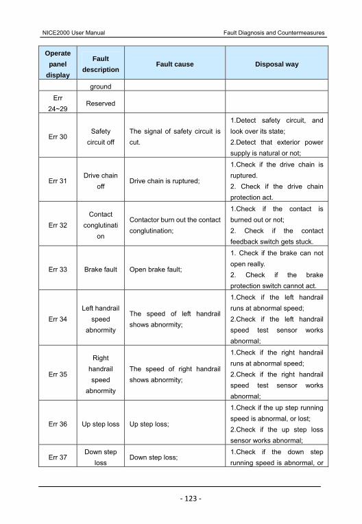
NICE2000 User Manual Fault Diagnosis and Countermeasures
‐ 123 ‐
Operate panel
display
Fault description
Fault cause Disposal way
ground
Err 24~29
Reserved
Err 30 Safety
circuit off The signal of safety circuit is cut.
1.Detect safety circuit, and look over its state; 2.Detect that exterior power supply is natural or not;
Err 31 Drive chain
off Drive chain is ruptured;
1.Check if the drive chain is ruptured. 2. Check if the drive chain protection act.
Err 32 Contact
conglutination
Contactor burn out the contact conglutination;
1.Check if the contact is burned out or not; 2. Check if the contact feedback switch gets stuck.
Err 33 Brake fault Open brake fault;
1. Check if the brake can not open really. 2. Check if the brake protection switch cannot act.
Err 34 Left handrail
speed abnormity
The speed of left handrail shows abnormity;
1.Check if the left handrail runs at abnormal speed; 2.Check if the left handrail speed test sensor works abnormal;
Err 35
Right handrail speed
abnormity
The speed of right handrail shows abnormity;
1.Check if the right handrail runs at abnormal speed; 2.Check if the right handrail speed test sensor works abnormal;
Err 36 Up step loss Up step loss;
1.Check if the up step running speed is abnormal, or lost; 2.Check if the up step loss sensor works abnormal;
Err 37 Down step
loss Down step loss;
1.Check if the down step running speed is abnormal, or
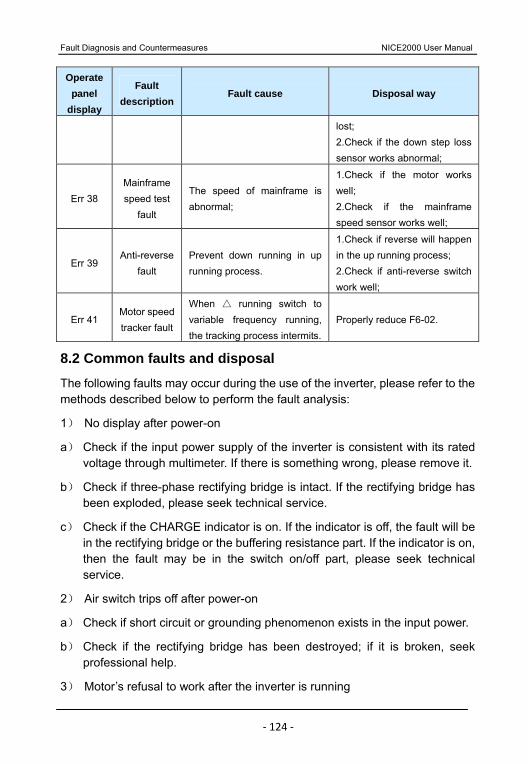
Fault Diagnosis and Countermeasures NICE2000 User Manual
‐ 124 ‐
Operate panel
display
Fault description
Fault cause Disposal way
lost; 2.Check if the down step loss sensor works abnormal;
Err 38 Mainframe speed test
fault
The speed of mainframe is abnormal;
1.Check if the motor works well; 2.Check if the mainframe speed sensor works well;
Err 39 Anti-reverse
fault Prevent down running in up running process.
1.Check if reverse will happen in the up running process; 2.Check if anti-reverse switch work well;
Err 41 Motor speed tracker fault
When running switch to
variable frequency running, the tracking process intermits.
Properly reduce F6-02.
8.2 Common faults and disposal
The following faults may occur during the use of the inverter, please refer to the methods described below to perform the fault analysis:
1) No display after power-on
a) Check if the input power supply of the inverter is consistent with its rated voltage through multimeter. If there is something wrong, please remove it.
b) Check if three-phase rectifying bridge is intact. If the rectifying bridge has been exploded, please seek technical service.
c) Check if the CHARGE indicator is on. If the indicator is off, the fault will be in the rectifying bridge or the buffering resistance part. If the indicator is on, then the fault may be in the switch on/off part, please seek technical service.
2) Air switch trips off after power-on
a) Check if short circuit or grounding phenomenon exists in the input power.
b) Check if the rectifying bridge has been destroyed; if it is broken, seek professional help.
3) Motor’s refusal to work after the inverter is running
NICE2000 User Manual Fault Diagnosis and Countermeasures
‐ 125 ‐
a) Check if there is balanced three-phase output between the U, V, and W. If there is, the motor wiring has been damaged, or the motor is blocked up due to mechanical cause.
b) There is output but three-phase is not balanced. It means that the inverter drive board or the output modules are damaged. Please seek help.
c) If there is no output, the inverter drive board or the output modules are damaged. Please seek help.
4) Inverter work normally after power on, but the air switch jump after running.
a) Check if there is short circuit between output modules. If there is, seek help.
b) Check if there is short circuit or grounding between the motor wiring. If there is, seek help.
c) If tripping happens occasionally and the distance between motor and inverter is quite long, consider add output AC reactor.