* m* M M W
109
y, . . y, .y - ^ ' : *, 7 #.* # # * % *,f * m* M M W ** - * ** ' * * "** * ' Wl k projwt nrort .ttbBitt^ to the foeelty of «r,ine.tio» Itoiveteity of the Uitoetor.rsna. Johoono.burt, in p.rti.1 fulfilootit ,« th re<Ft«Wt let the degree of Heeler of Seieoce dm fog o. rfm.
Transcript of * m* M M W

y, . . y, . y -
^ ': *, 7 #.* # # * % *,f
* m * M M W * * - * * * ' * * " * * * '
W l
k projwt nrort .ttbBitt to the foeelty of «r,ine.tio» Itoiveteity of the Uitoetor.rsna. Johoono.burt, in p.rti.1 fulfilootit ,« th re<Ft«Wt let the degree of Heeler of Seieocedm fog o. rfm.

rris
— v«aarifmSTTT •
M. » 0 W
....

Beee tapporting pendents *te constdered to be one of the ware critical dr. aline conponents. The? are subjected to a high degree of dynamic loading throughout their relatively abort, operational life and are inaccessible to conventions! intenanc* and inspection practices. The consequences of failure are extreme and a need Mists to understand the physical and meobaalcal properties of the support mechanism.
Therefore, this report discusses the reetlte of an investigation to determine the pendant loadings of the boom support system, with particular emphasis on the degree of load-sharing along with the operational factors, which affa=t their performance. The equilibrium conditions of the upper main suspension are determined by means of a computer analysis, and the ftotora which identify the pendant equalisation link as the source of a major geometric problem ate discussed. k number of practical techniques are presented to overcome the deficiencies identified by the investigation.

/#
unWiwiwrnwii
the author wild like to express hi* appreciation and indebtedne*» t@ tbe foIloving:
Hr 8, cipclat, faculty of Engineering, Project Supervisor, for his valuable counsel and guidance,
Mr Andres#j lies, AAC Mechanical Engineering Department for the benefit of frequent discussions and his interest andencouragement, as well as his cot league, Mr Aif van Mjh, for hJ* assistance during the test period.
The permission of the management of the Coal Division of AngloAmerican Corporation to publish this report is acknowledged. Tothem, and to Mrs toes Lowe and Mrs Adel# Palmer, who did thetyping, I express r-y thanks.

* * * * * M *11 111
g K L l W M * 1*
* * * * = 'vlll
oc**** *w * ^1 I * < * T M W * j * l * * * " * "
$
i^Bcoticrrtos
i.i
1.1
3.13.13.3
= 5 5 - - = - "
* * 1 "
4.11.1 --
m * * AMM.1818 Of C A M ST&OCTORfS
Tb* BUetic Catenary$ tk Awlyala
S»* O p t i m i n t i m
3.5 O a e w r s w y Criteria3.5 IsMMry of Iterative Procedures
273031353637
« © discussion
Imtarsmdiate Suspwieio i Pendants
6,1*3
« . w
*.1.1
* 1 ^
Historypattern of Load Variation
Nsasnraeants of Interwdiate Suspensions
363940
Effoct of Variations in Pendant Static Preloads 41 Load-Deflection Characteristics of Intermediate 46 Pendantsfactors affecting the asymetricrl distribution 46 el load in the dragline boom support system
%par Main Suspension Pendants 51
6.2.1 History 516.2.2 Upper Main Pendant Load Sharing 536-2.3 Determination of Equilibrium Conditions for 5J
the Upper Main Suspension System 6.2,* Magnitude of Link Error factor 566.2.3 Condition of Friction Coefficient 58
EECOMBNDATIOMS
7.1 Conclusions from Investigation... — — — -
6165

LIST or FIi
Fijruire
1.1
1.2
1.3
2.1
3.1
3.2
4.1
4.2
5.1
5.2
5.3
5.4
5.5
Power Shovel developed by U.S. Otis in 1835
Layout of Typical Dragline Pit
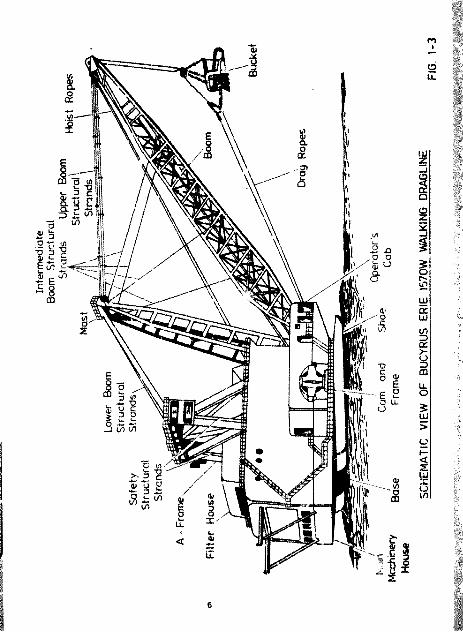
Seheaatie of Bucyrus Erie 1570# Dragline
ABCD fc I Design Considerations in theloading of Dragline Boons
Strees-Strain Relationship of Steel Wire Crilen
Cross SMt^Utn of a typical Bridge Strand
Hydraulic Tensioning Arrangement for Intermediate Suspension Pendants
Schematic for a Poissoo Strain Gauge Bridge on a hot metaled socket
Co-ordinates for the Elastic Catenary
Forces am a segment of the strained cableprofile
Load-Defletcion characteristic of an upper Main Suspension Pendant
tqpilibtisa of a rigid support cable trues
BtpiiUbriua of the upper HaSa Suspension Pendant :#$port System
m m
2
5
6
11
15
16
22
22
28
29
31
32
33
6,1 Pattern of Lower laterwediate Pendant LoadVariation*
6 .a Pm * tody Magrae o f t l» Boon
6.3 Loed-Deflection Characteris^xc* of Lower Intermediate Pendant*
6.4 Load-teflectiea Characteristic* ol tapper Intermediate Pendant*
6.5 Effect* of Error* in setting lower intermediate pendant preload*
6.6 Effects of Error* in setting upper intermediate pendant preload*.
6.7 Upper Main Suspension fabricated Link
6.6 Load-Link Equalisation Angle Characteristicfor Upper Main Suspension
6.9 Friction - Tension characteristic for ♦he LinkAssembly with identical length Upper Main Suspension Pendants for Load Case 1.
39
43
47
•*7
49
49
51
56
60
7.1 Upper Main Suspension fabricated Modified Link 62

Specific*' lone of Bridge Strend used oa Bucynse Erie 1570H Drsglinee
Fullback (creet) of Locked Coil Suspension Rope
Upper Main Suspension Pendant Length Measurement# as installed on the Kleinkopje Dragline
Field Test Rssultr for both Upper Main mad Intermediate Suspension Pendants »e measured on the Bucyrus Erie 1570V Dragline at Kleinkopje Colliery
Extent of load imbalance in upper main suspension pendants due to variations in setting of intermediate pendant preloads
Comparison between the dragline manufacturer1# calculated loads and the loads as measured on the Kleinkopje dragline (for upper main pendants)
Upper Main Suspension Load Accuracy Analysis
Resultant load share interaction of the dragline upper main suspension produced by a variation in each intermediate pendant as determined by a model of boom geometry
Suspension System Equilibrium Conditions for identical length upper main penw&nta (62,17* n)
Difference to Pendant Length necessary to result to efsat pendant tension# and equilibrium

LIST Of SYMBOLS
Quantity Syebol
1. Mensuratioe
angleare* Aco-ordinate# s*y#sdiameter 4distance along yeth •height hlength 1»X*radius t
2. Mechanics
acceleration gcoefficient of friction jj,force fmess #moment of force Khorisontal force 1vertical force Vstrain •stress @weight 6Young's modulus S

c 1
1 INTRODnCTION
1.1 Th« Brolveeent of the Walking Dragline
The United States of the 19th Century still relied on slow and costly wagon haulage for the distribution of bulk commodities to the interior of the country. Water transport was the key to the opening of the i erior, but at that time canal building was painfully slow with onlv about 170 kilometres of canals having been completed. This problem, together with the start of railway construction, brought a market for practical and economical dryland excavating machines.
Hollingworth. ^ * in his History of Strip Mining, described how the first excavating machinery was devcxoped originally for dredgir„ rivers end harbours. Dredging machinery dates back to at least the 18th Century, as in 1/96 the firm of Boulton and Watt built and installed a 3k,W steam engine of Watt's design in a scow, from which it was used to operate spoon dredge machinery. Some seven years later, steam power wee applied to elevator dredges and their use spread rapidly.
Adopting the existing design of steam dredge to a land baaed requirement was so difficult, that none of the early attempts was really successful. Then in 1835 a new type of excavating machine, a power shovel, was developed by a young American, William Smith Otis. His invention. Illustrated in Figure 1.1, was a major step fovward in excavation, swung from the centre, end had a power thrust to adjust the radial thickness of the cut. These features were combined with existing designs of a
1

self-propelled car oody, moaatad on standard gauge railroad wheel# and axles. The tw&ae basic motions: hoisting, swinging,and tnrustimg were all operated by steam power to produce a machine recognisable today. The terminology is self-explanatory, hoisting refers to the raising of the bucket by chains or cables passing over a supporting boom. Swinging refers to the excavator's turning motion, which in the original machine was delivered by a chain wrapped around a swing circle. Thrusting (cruwding) is the motion of th. bucket and bucket handle away from the boom towards the wore. When excavating sites moved away from rails, ss in the case of highway building and urban construction, additional mobility was required. This was first supplied by traction wheels and later by crawler mountings. Meanwhile, tits more efficient and versatile full-revolving design v introduced. Next came the replacement of steam power by more eaiily man/.ged and economical internal combustion engines andelectric motors
Figure 1.1 Power Shovel developed by M.S. Otis in 1835 (Mollingworth CD)
2

From this beginning the walking dragline has been developed primarily to suit various applications in the United States. The great flood control projects on the Mississippi and other rivers required long cantilevered boom machines with low bearing pressures to escavrte river channels and to build levees in the soft river bottom lands.
Draglines were used as auxiliary machines for many years n conjunction with stripping (power) shovels in surface coal mining operations, but it was not until 1930 that they began to be considered as primary excavators for overburden removal. By 1940, while stripping shovels were considered the favoured tool in most operations, the oragline wa*« being applied where overburden depths were too great for stripping shovel stacking capacity.
In the years between 1940 and i960 about nine walking draglines with an average bucket capacity of It cubic metres were placed in service. Two thirds of them were applied to coal mining operations and the bulk of *ve remainder to other mining operations, primarily phosphate. Almost all of this capacity was utilised in the United States. The following decade reflected a dramatic increase in dragline capacity as a result of the intensive development in dragline design and application. Maximum machine sise increased tenfold and boon lengths doubled during this period. Since that time bucket capacity has continued to increase and while gradual increases in boom length have continued, machine sise has remained stable.
It is significant that in the past tv r.ty years dragline operations outside the United States have absorbed a third of the new capacity as compared to a minor proportion of machines before that period. The first large walking dragline in South Africa was commissioned during August 1971 and since that time the local dragline population has increased to 22 unite.

1.2 Dragline Application
Moat drag]inea have baan &?: led to coal deposits, where the average overVardm depth does not exceed 40 metres, figare 1.2 shews a typical dragline pit. The type of overburden way vary from loosely consolidated to highly consolidated sedimentary materials» such ar ndstone or limestone, which require fragmentation by drilling or blasting. The major function of the dragline is to excavate a long narrow trench in the overburden, exposing a strip of coal. After the coal has been re# ved, tas dragline rt arses and excavates a new seam prallel to the previrae cut dumping the overburden where the coal has been removed. For this reason, draglines require long booms toincrease the range between the drag and dump points. Otherimportant factors are large bucket capacities and nid swing cycles.
A dragline supports the bucket with wire ropes. (See Figure1.3). The bucket is hoisted by pulling ropes oxer sheaves at theboon point and is dragged by ropes passing near the boom foot. The hoist *nd drag frmctione must be co-ordinated to obtain the digging operation. As long as the ropes remain tau , the bucket will remain upright. When the drag ropes are relaxed, the be at dumps. For a normal digging cycle the ucket is lowered vertically from the boom point until it contacts the overburden to be removed, where it is dragged towards the foot bus filling the bucket. kith hoist and drag ropes taut, the bucket is reeled out and up until it is almost at the boom point, where the drag rope t* -ion is released, the hoist ropes stopped and the bucket dumps. Th# «v^ng motion is co-ordinated *»ith hoist an (rag to dig and dump et almost any desireo swing cycle. In the simple case shown in Figure 1.2 the dragline sits on top of the material to be excavated and swings through an arc of between 45° and 90° to dispose of the material. A typical average cycle time tor tMs operation is 45 seconds.

Surface
wBirm u .
Exposed Seam /
PLAN VIEW
Surface
Cut W id th
SECTION VIEW
TYPICAL PIT ARRANGEMENT
5FIG. 1 -2
Inte
rmed
iate
Bo
om
Stru
ctur
al
SCH
EMA
TIC
VIEW
OF
BU
CYRU
S ER
IE
157Q
W
WAL
KING
D
RAG
LIN
E

Draglines used in opencast mining typically range in sise from machines equipped with 5 cubic metre drag buckets on 35 metre booms to a monster 168 cubic metre drag bucket on a 95 metre boom. A lumber of Bucyrus Er ie 1570W drsgl' >ee are operating in South Africa. The dragbuckets on these machines rang* in sizefrom 53,5 to 61 cubic ae"res depending on the ooom length.
All large draglines are powered by electric motors, which are fed by 6600 volt trailing cables supplied from an irpit 22 kVoverhead power line. Mobility for these large machines isprovided by a cam and shoe mechanism on each aide of the machine. These lift the rear of the machine and simultaneously move it forward. Walking speed is in the region of 225 metres per hour.
1.3 Statement of Problem
I . South Africa today business is at a crossroads. For many years industry has not developed the skills of technological expertise, due to its ea availability from foreign sources. With the advent of sanctions, industrialists will now be forced to compensate by long term development of staff and technological expertise, vis-a-vis the short term needs to apply technology for immediate commercial gains. Bmp isis must be placed on looking internally rather than externally for the solution of these difficulties. Therefore a conscious effort has been made toformulate a strategy to offset the loss of foreign technology with the ultimate objective of becoming self-sufficient.
As in the past, the trend in the mining industry is towards larger equipment. Mining companies usually seek out the single dragline, which will be able to handle the entire stripping requirement. This together with an operational requirement of about 7500 hours pe. annum requires 'hat emphasis be placed on developing components with high levels of reliability and predictability. This will ensure that repairs and replacement of components an be scheduled at times that will least effect the ewexell miming operation.
7

The greatest ameete of a dragline are inherent in the actual design of the machine. The greater the reach and dumping radius, the deeper the level of overburden, which cam be removed.Overburden up to 3b metres is well within the dumping reach of existing dragline capacities and removal can be achieved at substantially less total cost than by any other method. #.a overburden depth increases longer booms are required to dispose of the spoil at an adequate distan.e. Machines with 120 metrebooms are go'.ng into service, and it seems likely that boom lenfh will increase further. To maintain the same excavating capacity larger machines are required and both investment andoperating costs pet cubic metre will be higher than with amachine of the same capacity with a shorter boom.
from this objective, providing Bucyrus Brie 1570W draglines with a local supply of suspension rope pendants has proved to be a difficult and time-consuming operation. It highlighted the complication of working to extremely tight tolerances over long lengths and determined a need for effective length compensation. Following installation of the first set of locally produced pendants it was observed that the catenaries in adjacent ropes, connected to the same link, were different. It was naturally assumed that this was caused by errors in the lengths of theropes, which resulted in differing rope tensions and catenaries. This Initiated a set of field teets^®^to seaa are the loads on both the upper and lower main suspension pendants. The results of these tests were reported in September 1984 and January 1986 They established that indeed the loads in the ropes were notshared and variations in rope tensions in exce.ts of 100% were found.
The effect of unequal load sharing magnifies the already high degree of static and dynamic load as seen by the structuralmembers in normal operation. High static end dynamic load levels can increase the susceptibility of the wires to deterioratethrough normal fatigue mechanisms. The rate of deterioration can
8

be eigBificently woteetied by the effects of enviiomeeet. With ■eintenence end inspection of the oondents difficult, it is vitally ieportent to limit these deficiencies ss each ss possible.
4 further factor for wonuideration is damage or failure of a component of an operati nal dragline boom. The damage could be ss a result of an accident or a fatigue-induced failure during operation. This could be confined to a particular area of the beee where collapse may occur unless there is some geoeetric stability remaining after the damage.
1,4 Scope of Project
In order to meet these challenges a need exists to study critically and evaluate dragline operation and boon loadings in detail. Therefore, the initial «-orpose of the research is to develop an understanding of the physical and mechanical properties of the boom suspension system. Pendant loadings are to be determine4 by means of a strain gauge analysis and taose operational factors, which have an influence on their performance, are to be identified. In addition, it is required to establish the origin of the poor load sharing previously noted between a set of upper end lower main suspension pendents. Critical components are to be identified and their role in boom structural integrity ascertained. Practical solutions will be presented to overcome any deficiencies highlighted by the analysis.

2 CONSIDERATIONS IN BOON DESIGN
2.1 Beee Loading
The boon is probably the most critical single component of a dragline, from an engineering standpoint. This seemingly simple structure most he designed to withstand a medley of forces that interact and reverse continually during the loading, hoist, swing, dump and return operations
Loading of a boom can be categorised into thtee major areas.
(1) The compressive load as the b<on itself is basically loaded as a column.
(2) Because the boom is not vertical, but supported at a lower angle, the column deflects due to deadweight w*.th consequential loadings, which are additive to the working loads applied to the boom.
(3) The dynamic loadings which occur as a result of the swing cycle.
For a better understanding of the overall loading*2*of a boom, together with design considerations and rationale, consider the following*
10

iigcrs 2.1 Simplified Boos Loading Diagram (Sankey (2))
In Figure 2.1, the bucket load is shown as Force » which issupported over the boos point sheave and a Weight ti of the boos. The Loads L^, supporting the load and L^ to the winch, can be resolved into one Load acting on the end of the boos. Theresultant Force LR and the weight of the boos are supported bythe boom support penda.ita, which are in tension, and the boositself, which is in cot r.oaslon.
J-c
This shows the boos loads received into forces of compression L^, which act down the centreline of the bowt through the boos foot, and forces Lp perpendicular to the boos, which tund to rotate the boos about Point A. The load n the support pendants T will be that force necessary to prevent rotation of the Worn and maintain static balance.
11

/ T P
LP
The Force T is resolved into forces Tp perpendicular to the boo* to prevent rotation and its component down the boom, which is additive to the compressive forces. Thus,, one can see that the loads perpendicular to the boom ate cancelled to maintain equilibrium, and the resultant force on the boom is the additive effect of the compressive Loads L. due to the working load, due to the rope tension, and due to the boos weight.
The resultant working force o« the boom is illustrated in Figure 2,1,CO as a compressors force acting along its centroid.
12

^-EXTENDED MAST
SHORT MAST
L r
2.1(D) illumt h<bod h' £■
changing th# magRitud# of fore# dovn th# boo#. Since the boo# ia a pinned aeructur#, cb# compraaaiv# load nuat always act down th# centroid of th# bon#. By combining th# Load# and whicn ar* pinned o/f at Point B, th# raaultant load is ahown aa Fore# C . If th# naat ia extended to Point C. then the combined load of L_ and T . ia ahown by the Load C . By obaervation C, ia amaller than 0 . thua, on# can conclude that the higher the maat, the lower the co^reaaiv# load in th# boo# for a given work load.
Figi i Z.l(E) fa a mathematical r*pr#a*ntation of the aawe principle, which ahowa the compreaalve load down the boo# to bo a fmrnction of th# Load T in th# ropea and the a"gle between thm rope# and the boom. Thia force vari#a aa the coaine of the angle, thna aa th# angle between th# rope tnd th# boom incremaea far a hitter maat - the compreaalve load down th# boom decreaaea.
13
3 SUSPENSION PENDANTS AND ATTACHMENTS
3.1 Pendant Configuration
The boom of a Bucyrus Erie 1570# dragline is supported by four upper main fixed length suspension pendants. The;# pendants are solidly connected at the boo* point box, and by bronze bushed equalizer links to the mast head.
Two sets of intermediate suspension structural pendants support the lower boon chords at two points on either side of the bcoa. The structural pendants ire equipped with hydraulic adjusting jacks and are connected to the boom chords by open strand sockets mounted on spherical ball bushed pins.
Spacer blocks ate located along che length of the upper main boom support pendants. The s r acer blocks are clasped between the two structural pendants on each side of the boos and are used to minimize pendant vibration during the digging cycle.
3.2 Stress Str*' topertiea of Steel Cables
Three different types of steel cables are common in structural applications: structural strand with individual wires woundround a are, structural rope with several strands of wire, finer in diameter than in the strand, wound around a core and parallel wire strands with the wires bundled not twisted. Due to the differing method# of manufeetttre the effective modulus of
14

elasticity varies. The sore pronounced influence of the helice* gives the rope the eealleet aodulua, with an approximate value of E equal to 14C GPa. This say be contraeted with 170 QPa for a structural strand an4 190 to 210 GPa for a parallel wire strand.
Because the elastic liait is not clearly defined (see figure 3.1) the modulus of elasticity is usually calculated free the slope of the straight line that connects the 10 percent breaking load with the 90 percent pre~stretching load of the cable specimen. A pre-stretching load of about 55% of Uie breaking load is usually applied to remove the constructional looseness of the cables. This results in extension by the bedding down of the assembled wires with a corresponding reduction in the overall diameter. This reduction in diameter creates an excess length of wire which is accomodated by a lengthening of the helical lay. When sufficiently large bearing areas have been generated on adjacent wires to withstand the circumferential compressive loads, this mechanically created extension ceases and elastic extension
£ I $00 1OT 1000
.• STRUCTURAL
£ '500
r \S 1000STRAND
0 0,01 CXU2 0,03 0,00 at* o,oz ojoi 0,04 o,oa
STRESS
STRAINflpire 3.1 Streee-ltrein lelstloMUps of Stsel el re Cables
( Indw (*))»

Typically the elasrie limit <5% is reached at about 50 percent o.f ihe ultimate tensile atrengthOu. Ultimate tensile strengths of 1500 Mfa are regularly achieved, with ultimate strains of around 3 percent for rope and 6 percent for strand. Tests show rhat strand is stronger than the more flexible rope of the same size. Strength and stiffness, based as the? are on the nocioal cross-sectional areas, are affected by the class of zinc coating. Factors of safety vary, but a working stress of approximately 1 MPa (giving a factor of safety of 6 on the ultimate tensile strength) is routinely used on dragline applications.
Figure 3.2 Cross Section of a typical Bridge Strand (Maggie Rand (11))
Bridge strand usad on Bucyrus Erie 1570* draglines have the following specifications:
LowerMain
VpperMein Intermediate
Ditaaeter (aac) 98 89 57
So. of wires* 283 243 146
Wire tensile (MPa) 1570 ive 1470
Metallic Area fmm ) 5639 4700 1968
Modulua of Elasticity (GPa)** 147.15 148,6 171,7
Masa/m (kg/m) 47.95 30,73 16.27
Estimated breaking force (kN) 7995 6762 2766
laid op (54/4#/42/36/32/26/20/l4/#/3) All143 im l*id up (51/54/39/33/27'3l/15/#/3) right hmmd146 1# laid up (40/34/24/18/12/6*6/6/1) lay
** + 3% mftmr pr*#tr##si*g.
fAte 3,1 Specificationa of Bridge Strand meed on Bucyrua Erie 1570W Dragline Susp«ataiona

3.1 Mmnnfmctur# of P#ndan*. A3##mbli#«
A# i 1 ] umt rated in Figur# 1.1 th# boo# of tr w i*
5upDor*-f 1 hv f f i %m4 length #u#p#naion pendant a. "h# drmgl *
uanuEaccurers specification rm uiraa that fh< p#odan :a are
meaaurmd ur.der load auch that the finiahad laig%.ha ar^
Upptr Mainm 67,176 m ^ 0,006 at 1197 ' «
Clearly thia require* that cloo* attention - pa^d ^ ) f 1 .
of aeaauremenr ani rh* , ach&ent of tha ^er%io" .
Bridge mt rand usag* in Soutn Africa fa a? ' efL'uf.vr'y
reatriftec to the replacement of dragline :u«, n ...u ^frd^nta.
Aa thi * roii&f itutea a low and intermit'_#ni c .j^'cior.. local
manufacture ham nor been conaidered jiid . .'_r l .. 'i*aoa to
aupply iheae critical and varied itemc !:aa ha^ to * e r and.
Long lenRTh*. :p tn 1000 m, of preatreacwo atrand - Imported by
:he local wire rone manufacturer from which .i« ibly of the
varicua ' engthm of nendanta can be " . .«r' The local
manufacturer, Hairgie RanJ, h#va i . r J # m long
renaioning/compieaK.^n frame, whi"! enwL .e ft c cr' and to be
loaded to 17'"H 1«N and thua prndur* a*t» *»r iuita well
vithin the specified tolerancea.
For rhia inv*at:*arion * f-jll syr n: up; r mai^ auapenainn
pandan: a warn ca_ ibrated by cy. 11 - c l610 k* until
there *na no meaaurable change in ^ . a mir. 'f of three load
cyclea baing apeci fi»d. In the t;ata " three cycl*a
vert in fact auffici#nt *n "aetiie" tha rope. Once thia me# dona
the meaaurement of l*n*th waa undertak e ..
The technique u^ed to maaaure length waa to hrng pltmboba from
the centre of a permanent aockwt pin to the correepo adimg eocket
pin of a d u ^ y aocket. The b<jba are au.pemded directly above
graduated meaaurlng acalaa fixed the foummmtieam of %he
tenaioning irama. The diatance betveem the meeeuriug ecelem led
17
!
been set up u-ilng ateel tay#. Teieperattire effectswiicfe might alter the absolute value of length aefcsurement obtainei are eloiaieed by eaer -■ng during the nighl. Minor 'Mriutione in tampegat##'At* etaadardleed by a length adfnstaent -sing a coeffielast expansion f«rr strand of 12,5 * 10 6
rture variation.par "C of
At this point f*»a pendant i# r m o w d 2rtm the tensioning frame for the roplar of SjBe dumny socket by the permanent strandtermination « 'i# ttitait following the establishment ofthe pendt li positioning tha cast seta! wedgesocket c to ensure specified lengthtolerances. *he t JltfMi# it lifted into a socketing tower,«..*ich will allow at atraad diaaators to hang verticallydownwards from the ' fcicapsulatioa is then undertaken inaccordance with 463. Th«$ casting metal used forproducing ttte weiga **#£ be a n»lr entectic alloy, suchthat the affect sf daring casting does not result inany damage to the wire material, while ensuring a uniform distrihutioa ef tile W W r the wires together with a strongadhesive bond. 4
Following the eoa^la### #t this permanent termination, thependant is re-la#*#&l#&4* the tensioning frame and a tensioning load of 1700 ten appti*4c! W , e application of load Is beneficial in standardising the effect# af «aJge creep o» matched sets ofpendants. Due t# ikaga of the casting metal onsolidification as4 the presence ef micro blowholes andinformation of t&# Wieat, scree pullback of the castingcome in the socket basket cl® he observed. Thia is dependent on the degree of applied load and should be confined to a fewmillimeters in e properly prepared taraiortivn. Table 3.2 shows «h# r j*lt* #* *1 « lock«4 c#il mwpm lom r**« of 69 im
(3)

Losd PullbackkN an
600 0800 0,10C0 0,361200 0,551600 0,902000 1.192400 2.45
Table 3.2 Pullback (creep) of Locked Coil Suspension Ropes fSchneider (3))
A matched set of pendants is ateeebled from the ea»e original length of strant'. The results of the length eeaaureeente for the pendants installed on the Kleinkopje dragline, following the verification tsst wati within + 3mm, see table 3.3.
PendantPosition
Tensioning Data iCorrectedLength
M
AmbientTemp.oC
MeasuredLengthM
L.H. Top 12 62,169 62,175L.H. Bottom 13 62,170 62,1)4
S.H. Top 13 62,169 62.174R.H. Bottom 62,169 62.174
Teble 3.3 Upper Main Pendant Length Measurements aa inetelledon the Kleinkopje Dragline

4 FIELD TESTIWT
A.l Booo Raising Procedure
Raising and lowering the boom is done by using a separate boomhoist rope, reeved between sheaves on the A-frame and the top ofthe m a st, and attmc td to the drag drum to provide the necessary leverage. The ippir main suspension pendants, as well as the intermediate suspension pendants, ere attached to the mast prior to raising. Rotation of the drag drum raises the mast, and in turn the dragline boom, into a position, where the lower mainsuspension pendants are connected between the A trama and the.;ast. Releasing the boos taising rope transfers the weight of the boom onto the structural pendants. The mom hoist rope is then released, unrmewed and stored for future use.
4.2 Intermediate Suspension Hopes
Dragline booms are supported in such a manner as to eliminate, or at least minimise, the effect of deadweight bending. On Bucyrus Erie 1570V dragline® two pairs of intermediate suspension pendants are positioned above and below the midpoint of the boom. This has the effect of segmenting the boom into shorter ■embers, which support the bending components.
They are further intended to react the centrifugal forces generated when the machine is swinging. The forces would otherwise cause the boom to deflect radially outward and, since the booe is essentially a cuLina, a buckling failure could ensue due to the eccentricity so generated.
20

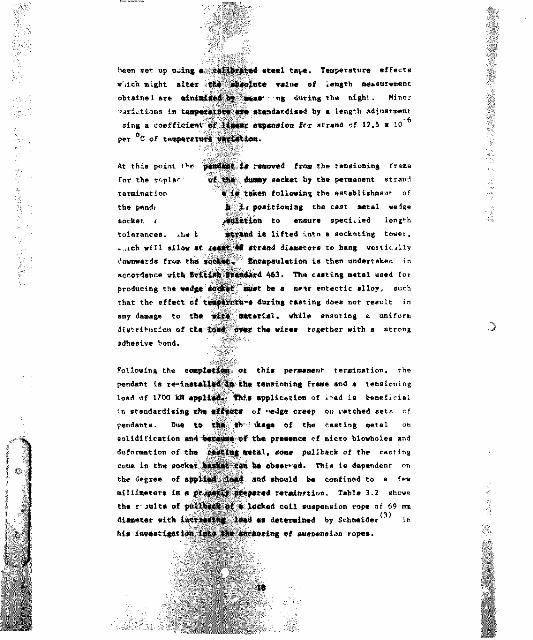
Following installation it is a requirement of the manufacturer that these ropes be preteasioned to a normal static tension of 260 kN for the upper intermediate ropes and 285 k* for the lower intermediate ropes. Teasiontng is achieved by means of a portable hydraulic jacking system (Figure 4.1). k portablejacking unit is connected to the cylinders and vhea the correct pressure is achieved, the tension is mechanically secured byme a n s of lockouts. Tensions on both the upper and lower, left and right hand ropes are set independently but simultaneously. It was found that, to achieve the specified preloads, several a p p l i c a t i o n s of tension by the jacking system on individual ropes were necessary to oc aim a balanced »sult.
4,3 Measurement of Pendant Loadings
Two basic techniques have been used for * he measurement ofsuspension pendant loads either direct strait readings on legs of sockets or indirectly am the pressure gauge provided for the intermediate pendant tessioning system. Figures 4.1 and 4.2 show the principles of both types of measurement. It is essential that strain gauge bridge circuits are arranged, so thate x t r a n e o u s bendlog and torsion e f fe cts are eliminated, and so that the cor-ect loads ar e produced, when the loading between tnelegs of s o ck et* ia mo t p e r f e c t l y ce nt ral .
In most cases, calibration is desirable, but this has not been p o s s i b l e in the m b s e m c e o f a s u i w b f e sp e r e so ck et. E x p l o r a t o r y w o r k has beeu undertaken however, by employing the results of a previous calibration exercise on a socket analsgous to that used in the Kleinkopje measurements. It is estimated that thea c c u r a c y obtained by this method is within 10-15 percent ofactual values. This exercise is detailed under Appendix B.
Prior to the recording of suspension pendant tensions, the zero stress reference position was established. This refers to the
21
PRELOAD INSi RUCTIONS# iMMumw wma* t» mo* uttm
MOK&j m m I m m 1n s r xmn. «u# stumb iwras susp siiweAN£M m iSODN EMPTY m m ESN EKFtY
H0RI1 O-SL K X W Homz M L BJOCETi no# UJMM 3ie m w 2#0kN 32?kN tow Wwil 2MhM
won. **»* mmcATU MKf n* MgLMDDMECTLY M
;. &L M P W M D uwa0-&1 OETENMMB UMO CAM I]. B#rr aucw MFwe m#TY mucw suyoom megan* #onw #om. of- '""MO LO*c ?
LOW# «OQ@T NUTrBmOBE
Figure 4.1 Hydraulic Temloning Arrsnge@ent for Intermediate Suspension Pendants
e m t a m g u m Mfigwtm 4,2 Schematic for Poisioo Strain Gauge Bridge on a hot
■staled socket

condition wt wttich the strain gauges are calibrated t j a zero atr-atic level, It was obtained by supporting the beo® on the ground with all pendants and booe raising ropes slack. All subsequent strain measurements were then taken in three well defined load conditions.
bucket and rigging on the groundbucket empty, suspended Helow boom point boxbuckct full, suspended below boom point box
following the raising of the boom and the pretensioning of the intermediate pendants, with both bucket and rigging on the ground as required by the manufacturer, the dragline was operated on normal excavation for a few days to "settle" the boom suspension system. Prior to mny massurements, the intermediate pendant pretensions were again checked and readjusted to conform with the manufacturer's requirements. The strain gauges were then connected to th& switch and balance unit and the zero s t re ss position, as established with the boom on the ground, set for the strain gauges on the strain indicator.
The test sequence for the boom suspension gauges consists of:
1. Balance and calibrate the strain gauges with the bucket on the ground and with the spreader bar and dump nlock weight off the hoist ropes. The bucket should be positioned directly below the boom point shea tree equivalent to maximum reach. This position represents losd case 1.
2. Hoist the e-pty bucket at maxima reach to e position justbelow the h. 1st trip-out point. This position representsload case 2.
3. Hoist » full bucket at maximum reach to a position justbelow the hoist trip-out poire. This position representsload case 3.
13

4. Oa coepletion of the full bucket test, return to theststting point and set the bucket on the ground, making surethat the spreader bar and dump block weight are off thehoict ropes. Rtcheck the strain gauge calibration.
The tests were established with the dragline oase supported under average ground conditions, with the supporting surface blasted, covered with on* met re of shale and dosed l»v»l.
To establish the effect of a variation in intermediate pendant pretenrions, on completion of the series of tests as detailed above, a right lower intermediate pendant pretension waa reduced by 40 kN. The remaining intermediate pendants pretensions were not readjusted to their specified values, but allowed tocompensate for the maladjustment to the right lower pretension. A second series of measurements was then undertaken using theprevious test sequence.
This was followed by a further set of measurements to establish the effect of a variation to a right upper intermediate pendant,also subjec • to a reduced pretension of 40 kN. Before thisadjustment was undertaken all intermediate pendant pretensions were re-established to the manufacturer's specified values and thereafter allowed to compensate for the reduced right upper loading.
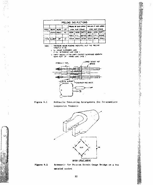
The full series of test results for the Kleinkopje machine aresummarised in Table 4.1. Table 4.2 shows the results andillustTstea the extent of imbalance in maximum loads that can occur, because of error* in setting initial pretensions.
2*

Rope Loadings (kN)
Bucket onRope Pcaition Ground
Emptyducket
FullBucket
Preloads as specified
Left Top 290 519 882Left Bottom 438 719 10 82Right Top 246 471 81 0Right Bottom 3*6 637 1006Left Upper Inter. 260 320 37 9Right Upper Inter. 26) 320 395Left Lower Inter, 2 8 5 285 ^02Right Lower Inter. 285 285Preload reduced on right lower inteimediate
Left Top 255 49 4 87 2Left Bottom 40 2 68 9 10 84Right Top 225 433 801Right Bottom 3 7 4 630 1010Left Upper Inter. 212 285 395Right Upper Inter. 250 ?3l 363Left Lower Inter. 290 299 302Right Lower luter. 244 244 244Preload reduced on right upper intermediate
Left Top 236 -*56 801Left Bottom 395 66 6 10 34Right Top 205 4 1 2 738Right Bottom 368 6 3 9 971Left Upper Inter. 261 319 395Right Upper Inter. 221 296 383Left Lower Inter. 284 26? 284Right Lower Inter. 284 28' 290
Table 4.1 Field Test Results for both ’ipper Ha in andIntermediate Suspension Pendant# as measured or the Kleinkopje, lucyrua Erie 15701* Dragline
3 SI
% 51
5 §!
I:
a
a
t
31
o #
il
3*

Rep* Wadia** (») fercertage Variation
Position Losd Came 1 Load Case 3
Left RiVif Left Right Klght
Q c n c s E ] a amotw. & &
7 1 # * 1 4
Q E CPreloads reduced on Right Lower Intermediate
^ C Z 3 ] ^ O E D m i*«t«m m
w ; M #
C S DPreloeda reduced on Right Upper Intermediate
Top ______ _ 236 205 ______ _ ______ _r R % i n c n
#o t * j gM l 17)
U S E
W.2 I_Z1% _U1 i*w no#
C O Z l
49 4 433
j m j a s1163 1063
n r n
45 6 41 2
J&* - I S11 22 1051
c z n
r n n ] r r n i r
10 82 100 6 19 64 1*1*
c n z r w ? i
_ H 3 ]
3 3 ]
872 1 10
1084 10101956 1820
n a
m *1*35 1709
I w.l I
E L
t*l» *«1 lEtee* at tot6 liAelwiee *m V f f x Wale Suspennion Pendants 4ee to i variation in tatting of urndm# l»W #.

c 5
5 STATIC ANALYSIS OF CABLE STRUCTURES
A cable assembly of this for® belongs to the category of geometrically nonlinear structures, because the', are structural mechanises, the stiffness of which depends upon the stiffness in the cables and because the high tensile steel used in the wire permits strains which are approximately six times greater than those used in ordinary structural steel.
The non linear behaviour of this type of structure oust be taken into account in analysis, since conventional linear methods vil1 overestimate the displacements when the structure is st iffen lug, and underestimate the displacements when it is softening. A unifying approach to the analysis of both linear and non linear structures is to consider the dfcterminat ion of a system equilibrium equation u d its solution by means of an iterative process, fhe position of equilibrium being reachtd when both sides of the equation are equal.
5.1 The Elastic Catenary
When freely hanging cables are connected to a common attachment, general linearised solutions developed to the solution of cccesary problem# are no longer adequate, and other methods of determining cluster response must be found. One possibility is to use the finite element method by dividing the cable up into several elements, writing approximate equilibrium and ecepatibilit'' equatlone for each element, combining these into a global system for the complete pendant assembly, and so
27

proceeding to detev'-sioe its r#*spon*e. Aa alternative approach is, h o w e v e r , to use the exact analytical solutions for the
Structures, which in contrast to th e suiti-element techniques, represent the pendant by a single element. The potential saving in computer time makes this method mere attractive for static r e m p o n m e c a l c u l a t i o n # .
Dragline s u s p e n s i o n pendant* resist a p pl ied load by changes in both tens ion and geometry. A c h a r a c t e r i s t i c of r e l a t i v e l y flat suspended c a b l e s , is that em ai l changes in ca b l e length give rise t o su b s t a n t i a l c h an ges in ca b l e g e om etr y.
Th e s u sp end ed cable shown in Figure 5.1 is s u s p e n d e d between two fixed points A and B w h i c h ha v e Cartesian co-ordinates (0,0) and (1 ,h), respectively. Thus the s p a n of the ca bl e is 1, and the relative v e rt i c a l displacement of the ends is h. The unstrained length of ca bl e is d&ere L is not n e c e s s a r i l y g r e a t e r th an (1"* + althoiit obviously cannr«. be much * ifE o ok e's lew is not to be v i o l a t e d . A point in the c a b l e baa Lag rangian c o - o r d i n a t e a In the unstrained profile (the length of ca bl e fr o m the o r i g i n to thet point is s wh e n the c a b l e is u n i c e d e d ) . Under self-weight of W (- mgL^) this point moves to o c c u p y its n e w p o s i t i o n in the st ra ine d p r o f i l e d e s c r i b e d by C a r t e s i a n c o - o r d i n a t e # x and y a n d L a g r a n g i a n c o - o r d i n a t e p.
elastic c a t e n a r y developed by Irvine (4) in bis b o o k , Cable
X
Z?f i g u r e 5.1 C o - c r d i m a t # e for tb # K l ae tic C a t e n a r y
( I r v i n # (4))
T h e g e o m e t r i c c o n s t r a i n t to b e sa t i s f i e d i#
2#
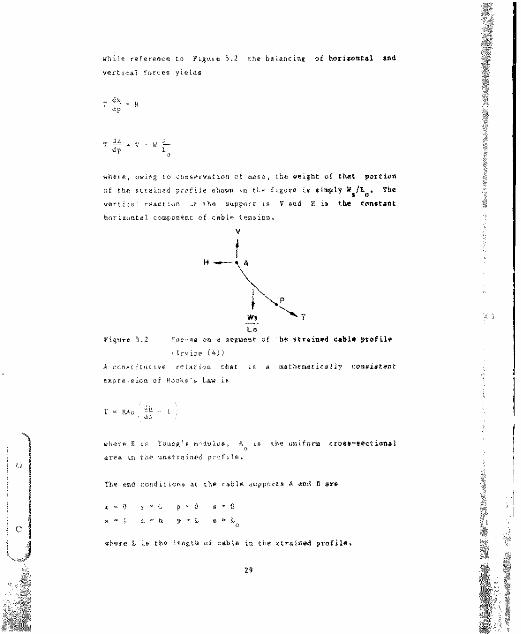
w h i l e r e f e r e n c e to F i g u i e 5.2 the b a l a n c i n g o f am dve rt i c a l fo rc e# yield#
w h e r e , o w i n g to c o n m e r v a t i o n of m a m # , the w e i g h t o f th at p o r t i o n o f the # t r a i n e d p r of ile mhown in tke figure i# # im pl y W ^ / L . T b * ve rt ic* ^ r e a c t i o n ^t the #u pp ort i# V an d H i# th a co ma t a m t h o r i zon ta l c o m p o n e n t of ca bl e te n# ion .
L oF i g u r e 5.2 Fo rr e# o n a #e gm #nt of h# # t r a i m # d c a b l # p r o f 11#
( I rv ine (4))A c o n m t i t u t i v e rr ia tio n Chat i# a m a t h e a e c i c a l l y co a a i a t e n t e x p r e .#ion of R a ok e'# L a w i#
w h e r e E i# Y o u n g # a-^dulu#, A i# the u n i f o r m c r o # # - # # « t i o m a la r e a in the u n # t r a i n e d pr of ile .
T h e end c o n d i t i o n # at the c a b l e #u pp ort # A and b are
a - Q % * ( , p - 0 # ^ 0% - l * - h p " L # " L
w h e r e L i# th e length of ca b l e in the * t r a i a # d pr of i l # *
VI
29

Irvine now derives the #tr »in#d cmbl# proJil#.
that describes the
or-(».R,/L.\ 2 \ 1/2
Pendsot Sti ffnees Aaalyele
T o d « t * r * i n * th* b m m i c lo ad - h m r # r t # r l # f i c (ord r m g l i n # «u«t._a#ion p e n d m n t * % # % # ! % # # # # # # d # r # t a a 4 i n # of thoiret mt ic and d y na mic re mpoma*. 0 * # # # y * f f h i m k i a # about thiaparameter is to consider it as rea«*feiiltg the stiffness ot twoa p ri ng# ir aeriea. C o n a i d # r a * f * * * o g & l # i m w h i c h th # en da# r # be i n g a t r # t c h # A apart. Bom# # w l a t # o c m # u p p l i # d iag # c m e t r i c . b # c # u a e th # ia i I####. T h i a a t i ! f o # a a ia'MThm rfkminlng #tll mmiml w# by a t*rm like KA.
* c o m b in«Tio n of rh*#« r*» *fl— W th# r— p o w of tha« u a p a n « l o n pa ad irr . C o m a i * « T * paw l an t that hu &«c ' o i a l y to th a ch o r d a p a m ^ i m # ^ # m * M t i a # p o i n t # a n d i.t h a r a f o r a ta nt and « r a i * t . * w t K r a t c h to ra al ita p p l i e d load, but th ia . t r a t o k i m # t m * # & * aacoad or d a r in tha a d d i t i o n a l d a f l a c t i o a . aa th * * A w # I n t a n a i o n araa b w n t . O n t h a o t h a r h a n d ak a# I * I f f la o l . la .a , 'n thac a t a n a r y t h a n tha r a l a t i a # i n a a t a n a i M l i t y » * n a t a l c a b l .a a n i l a a t a itaal". M d l t i a m a l # # * a l a » « * m W x w r m t a d to tba

f order* Ncatiee the loaded peodant can apt a new profile that dees net necessarily depend on changes in cable length for it* esietewee. Soeewhere between these two limits upper and lower mein #u#p#a#ion pendants will be found to operate.
The result:fces losd deflection characteristic for an upper main auapaasiem peatiant is plotted in Figuie 5.3 and is based on anomimsl ef 62,176 a.
61.5-
61,3-
100 200STRAND TENSION (kN)
Figure 5.3 Load Deflection Characte. istic of an Upper Main Suspension Pendant
5.3 M M e l Deveiopsent
Thu cable support structure will be analysed ay a single entity, and t h e aaalyais proceeds on the as s u m p t i o n that its top and b o t t o m c h o r d s do «-' react i n de pen de ntl y. The relatively small w e i g h t o f t h e eabi has been included, so that the free hanging geometry is specified by the cable ten#ions, the p o s i t i o n of the link sad the stum. The small longitudinal movements of the cable Btracteeei saeeciated with the vertical movement of the structure under ie ed . West be allowed to occur Freely. Bven though the e h r u e t * r * i respense is in general nor linear, it ia
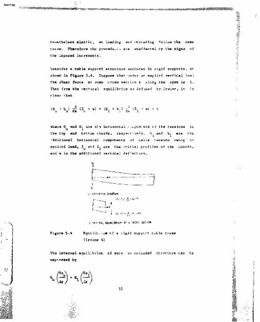
n o n e t b # ! # # # # l a # t i c . #o l o ad ing «n d u n l o a d i n g f o l l o w tb # ma m#curve. Therefore the yroeedtuc-j are unaffected by tb# signs of th # im p o a # d i n cr #m# nt m.
C o n # i d # r e e m b l # a n pp ort a t m c t u r # a n c h o r a d in ri gi d a a p p o r t # , arshown in figure 5.4, Suppose that under ar a p pl ied vertical loeC t h # « h # m r f o r c e at a o m # c r o a # w a c t i o n a a l o n g th a #p a n ia S.T h a n from th# vertical equilibrium as defined by Ir vi ne, it is c l # a r fhet
w L # r # R a m 4 XL ar a t M h o r i a o n t a l ru ^ion* ntm o f th # T a n a i o n a inthe top a n d b o t t o m chords» respectively, h^ and h. are the a d d i t i o n a l horizontal component# of c a b l e tension owing to a p p l i e d load, 2 an d Z. mr# th # in it ial pr of i l a s o f tb# c h or ds.a n d w is th# additional v e r t i c a l deflection.
T h # i m t e t m # ! e q u i l i b r i u m o f a u c h an u n l o a d a d s t m c t u r # c a n ba # % p r # s # # d h y
c: OEFmfiM
F i g u r e 5 . 4 Eq nl lib . .um o f a ri gi d s u p p o r t c a b l # t m a a (Irwim# 4)
32

kithough the drag Iine upper main suspensija attaebaeBt at the boo® point box may be considered to approximate a rigid nupport, the lover end of the pendants are connected at the mast head oy means of a rotatable link. This therefore necessitates some modification to the general approach given above» in that the pendant profiles cannot be assumed to adopt unifote profiles even under equal length conditions.
Considering now the determination of an equilibrium equation for the dragline ca bl e support structure over the desired range of dragline boom loading. For the m e c h a n i s m shown in the accompanying Figure 5.5, the relationship betwevo link geometry and motion ca n be found from consideration of the applicable geometric runctions to be:
- (c t«w d ewS}-M( <d ewiji. c wm p)
Figure 5.5 Equilibrium of the Upper Main Suspension Pendant support sy s t e m
If the chorde dr« considered to be elastic catenaries, as d#w#lop#d io tb* prtv.oa# moctiom, th# imtormml equilibrium im the initial profile is satisfied by the followibg dmensionless quant itiei
33

r " H * * " ' ''u ' % ^ 'i: * * *1 *- C * e * co m g
wh m r m t h * harimoritml a n d v e r t i c a l c o m p o n # n t m H ma d V o f th# t m n m i o n at »ha u p p e r en d o f the i n it ial p r o f i l e h a v e b e e n d a t t r m i n e d fi o * th e im pl ici t a q u a t i o n e
E A
nr ( Z - i2 1/Z . 2.1/Z
(For c a l c u l a t i o n pu rp o m a a tha i n ye rma h y p e r b o l i c a ine ha a be an ra pl a c e d b y itm l o gm rit hm ic r e p r a a a a t i t i o n . n a r^ ly.
h * In (a
The fu n c t i o n a l c o n m t r a i n t m w h i c h hm vm to m a t i a f i e d in the d a m i g n m o l u t i o n mr#:
' = + "l)' *
%* er # G ia the v e r t i c a l - o a p o n a n t of "ha ma m # of th e .ink m e ti ng mt itm n e u t r a l a x i a mnd
%#here m g l la I* If-v aig ht of the c a b l # rr o m th e o r i g i n of th# u p p a r a u p p o r t L_ th# h o r t a o n t a l ta ng ent of th e c a t a n a r y ar d th** mu b m c r i p t r e f a r m to the lo w e r c a b la mu pp ort .
3A

'u + V2
T
where T represents the aaxiama cable tension acting at the upper mupport.
Regional constraints, Vhi have to be satisfied in the design eolntior due to the flx#d gK-Mmetry of th# upp fr euppnrt of th# cab]## are:
Horizontal remiraint
D % = ap e n 1 * n% - ap am u » Da ^
Vertical remtrajnt
where Dx and Dy represent ';he wptrific location dimenrionr of the p a n d u n t m at th e b o o a po i n t Lo%.
Every coaplea deaj,j problaa haa ita ova uniru# characferietic that make it a ap#ci#l eball#ng# o tradJ tioaal optiaiaation alKcrithaa. It waa therefor# aecemaary to try a mmber ot r mmercial aaftwpre program### to fetermine the beat algorithm to "lit thia particular problem. Theoretically, the miniaiaation can take pJ ace aloag any defined d#c#nt v#crar. In thia optiaiaation, th# a#tbad of ateapaat daacant *#« /oaad to b# practical.
5.4 Computer Solutloa
35

Tb# software progratan* "•Eureka", availab fro* Borland , einiiiises functions by the steepest descent ^ethod. The solution path gees from the initial point to th# constraint manifold and then lies or. the constraint manifold until convergence is achieved. The marifold of points has a Rtesannian metric, which ia derived from the Hessian of the function br«.ng minimised. The COBatraints are a enforced by means of a user defined penalty function.
^.5 Gonvergency Criteria
A number of different convergency criteria may be used to terminate the iterative process. In the structure under investigation the method used is to evaluate each side of the solved equation individually and then compare the two sides; the difference between the two result should ideally be 0. However, in practice, the most accurate criteria zn which to judge when the problem had converged to a sufficient degree accuracy was when the changes in displacement of the hovise--- and vertical regional constraints were at a minimum. Fo. purpose ofdesign, sufficient accurf:y was assumed to be ach* , wh«n thedifference in equili-iriuia was reduced to between (,01 percent and 0,1 percent.
5.6 Smeary of Iterative Procedures
The main steps in the iterative process in determining the magnitude of pendant tensions of specified lengt\, to achieve #trmctur#l e^iilibrium may be summsrised aa ollows.
t%fc"# be start of the iteration acheme:
Specify th* prnbleu ;— ' ' r'infa
— Fri*"r4nn Coeff ""- Yo t a i or c e o n L i n k (S pecific Lo a d Case)^ P#Want lengths as detevmivd by snppli«r.
*

(b) for th# perpo«#f of initi#ll##tlon, omtimmt# #ach pendant lo#d mnd individually cmlculmt# th# two coapowntm H mnd V of th# t#nmion mt th# opp#r mnd of th# profil# fro# th# implicit #qumtion#.
= i r * t t (j ) - 7 h"1
> ^ ! ( " » T ( - - ( - ) T
(c) %nt#r th# d#riv#d H , M_. V V. mm initimlimmtionm.
(d) Th# nominal v*rticml dimtmncmm b#t*##n th# pendant mttmchm#ntm h h, mr# #nt#r#d m# #p#cific conmtrmin e.
Th# mt#pm in th# it#rmtiv# proc#dur# mr# ch#n mm fullo*m
8t#p 1 Solv# for th# totml «ymt#m rmmctionm mnd ch#ck if th#problem hmm conv#r$#d. If th# di#plmc*acct in th# r#gionml coAmtrmintm I# Immm thmn 0 . 1 p#rc#nt wtop h# cmlculmtionm mnd print r#m%lt& if not. prcc##d to St#p 2.
@t#p 2 Dpdmt# th# initimlimmtion ot 7 mm *#11 mmth# indivlduml p#ndmnc tmnmion# from th# cmlculmtmd rmmultm of th# prmvioum cmlculmtion, Chmng# th# nominml vmrticml dimtmncmm h^ h_ fro# conmtrmintm to initimlimmtionm.
St#p 3 R#p#mt th# mbov# itm^mtior by rmtuming to ft#p 1.
37

c
6. RESULTS AMD DISC0S8I0*
6.1 lateraediet? Suepensioa Pendants
6.1.1 History
In 1977, boob after the introduction of Bucyrus Erie 1570 ¥draglines into the local coal mining industry, problems developed in the termination* of intermediate suspension pendants. The original manufacturers design of the termination failed from betiding fatigue due to a "dogs-leg" deeigfl. As a result of this the design was changed to a system utilising straight bolts. Unfortunately these too suffered from bending farigue problems in spite of improved materials. During 1985/86 an investigation into those repeated failures cm#* to th# cootlu#iom that significant b&nding stresses were present in th* termination#, due to irperfect seating of the nuts of the preloading bolts onth# socket bridg# piece. A# a r#ault of this investigation, thetermination design *a# refined to include parallel machinedbearing faces and also ensured that the bolt holes were normal to the bearing faces.
This revised :#rmir mt ion greatly reduced tb# incidence offailures of the terminations of intermediate suspension pendants, but has not tn all case* produced an adequate serfire life. The a*#* inv##tigmlien into preleaiing bolt failure# al#o identified oxial forces in the bolts greater than the design loads. This was, however, aot pursued and the source of the overloading and its ousequent maidisfibation of loads a I lowed to continue.
3#

6.1.2 Fsttem of Load Variation
typical chart records for the inner and outer bolts of the left hand lover intermediate are shown in Figure 6.1. These aeaeureeents were obtained from the investigation into the failure of the preload bolts referred to under Section 6.1,1 on a second machine. They are however believed to be representative of the pattern rf load variations present during normal machine operation.
TENSION INNER BOLT
Figure 6.1 Pattern of Lower Intermediate Pendent Load Variations (Pry (6))
They illustrate that during a swing cycle the load variations are fairly repeatable. During digging, vibration of the boom (induced either by impact as the bucket is released or -etrievt d, or by drag load variations) causes oscillations in rop "about the mean static tension level. Average pendant - os/, increases as the bucket is hoisted and the dragline ewiags, maximum loads being achieved during the simultaneous swing/hoist cycle. Generally the maximum rope load occurring for any cycle will correspond to the peak lavel reached during the boom induted oscillations towards the end of the hoist cycle.
Additional load components are Induced as # re.mlt of let iral vibration of the ropes at a frequency of about 1,6 Ks. Mean axial load in the rope is significantly affected by this vibration.
3#

6 . 1.: Lead Measurements of Intermediate Suspension Pendants
Measurements of static rope loads mere ^dertaken with a view to establishing the influence of intermediate -atic pretension andits interact inn on the redundant pendant cyst--
The manufacturer's computer analysis used in sir , the boom chorda and suspension pendasta, only utilises a single it^her to simulate the two right-hand upper main pendants and a igle member to siuulate the left hand pair. Therefore this approachdoes not allow for the calculation of a differential load i n
direct comparison with the measured values. With the simple pin connected design no consideration was given to any differentialin loading occurring in the programme output
Recognising these deficiencies the manufacturer's design analysis or d the following results for direct comparison withmeacuied slues from the Kleinkopje dragline. The measurement technique riliffd both strain gauged sockets and pressure readings iron the intermediate pendant prestrassing equipment, as diacusK*d in Section 4.2.
Load Caco 1
Pendant LocationCalculated
Loading (kN)MeasuredLoading (kM)
Variation(kM)
Upper Mains 260 averaged) + 75.0Lower Intermediate ?ms M S ..Tapper Intermediate . >0 260 (pr* ''d)
Load Case 2
Calculated Measured VariationPendant Location Loading (kM) Loading (kM) (kM)
'pper Mains 516 566 (averaged) +50.0, wjwer Intermediate 327 320 -7.0Upper Irtermediate k*2 2#5 -7.0
Table 6.1 Compar’son between the dragline manufacturer'scal alated loads and the loads for the upper main suspension at measured on the Kleinkopje dragline.
AO

6.1.4 Effect of Variation* in Pendant Static Preload*
To anal, se and assess the accuracy of the pendant load aeasttrittg for the specific variations in setting initial tension, a*a;>plied to the intermediate pendente of the Kleinkopje dragline, and their consequential effect-< on the upper main pendantsrequired the following amalyaia.
ronaider a diagram of the boom supported at iv* pin, lowerintermediate*, upper intermediates and upper mains, a#illustrated In Figure 6.2. The - ’* of the products of eachpendant load and its moment arm about the boom foot piu meetremain constant for each of the distinct load conditions (backet on ground, empty bucket and full cucket). Therefor# the ffacts of variations in intermediate pendant preloads can be a- iseed against those calculated for Individual load case# at ~lr specified "reloads.
affective strand tensions ir respect of the fleet angle of the pendants from the plane, perpendiculur to the boom feet, are as follows for the Kleinkopje dragl ne geometry. Lower intermediate (8,28^ deg) is equivalent to *8,956 percent of measured tension effective- in resisting front end moment, upper intermediate (5,575 deg) is equivalent to 99.527 percent and the upper maims at 0 deg are 100 percent effect vs. The calculated moment arms of the pendant lines about the boom foot pin# arm: lowerintermediate 32,004 m, upper intermediate 42,266 a and upper malm 40,465 m.
In this analysis the reference moment about the boom foot pirns has been determined from the pendant tensions, derived from tbs dragline manufacturers computer model of the boom. For example, considering load case I.
41

Pendant No. ef "tesign Moaent Peteentay* MomentLocation Pend«its Loading kN. /.ra a Effective Mte
Upper Mai ., 4 * 260 • 40,465 • 1,0 42084Inter. 2 * 285 * 32,004 * 0,98# 18052
Upper Inter. 2 * 260 * 42,266 * 0,995 21874
Reference Moment 82010
This can be iseesed against a moment derived fro# the peed«Bt tensions established during the field tests. Consider the reduction in prelo*J * he right lower intermediate.
Pendant No. of Location Pendants
DesignLoading kN
Moment Arm m
PercentageEffective
MomentkNm
Left Top 1 255 a 40,465 * 1,0 10319Left Bottom 1 402 * 40,465 * 1,0 16267Right Top : 225 * 40,465 * 1,0 9105Right Bottom 1 374 * 40,465 8 1,0 15134Ur -r Maine 50825Lefr 1 212 * 32,004 * 0,989 6714Right 1 250 32,004 * 0,989 J i l lLower Inter. 14631Left 1 290 42,266 * 0,995 12199Right 1 244* 42,246 * 0,995 10264Upper Inter. 22463
Measured Moment 87918
This represents a 93 percent correlation in measured load accuracy with that of the manufacturer's computer model.
42

1 1
*
y41
Pirate
6.2

M*a*mr*4 lo*& *ect*r*t», detereinea is thie m * m t ter both load €««•• 1 and t la reapact of the 40 ItH reduction to upper and Iowa* intermediate pendants as well as at the specified preloads is listed in Table 6,2.
W a d Case 1
PreloadingCondition
Reference Moment kffn
, -----MeasuredMoment kM*
Correlation
As Specified 82010 04230 0,87Right Lower Reduced 82010 87919 0,93Right Upper Reduced 820*0 86984 0,94
Load Case 2
PreloadingCondition
Reference Moment kNm
MeasuredMoment kN*
Correlation
As Specified 132 036 139 905 0,94Right Lower Reduced 132 036 133 994 0.99Right Upper Reduced 112 036 131 410 0,99
Table 6.2 Upper Main Suspension Load Accuracy Analysis
Table 6.3 shows the results from the manufacturers' boon model for a deviation of 7.6 kM from specified preloads in both intermediate pendants. It . ustrates the imbalance in maximum loads ’thich earn occur, in respect of lead case I, because of errors in setting initial tensions in intermediate pendente.

Daetuiia* Lower Intereediete tenelon (Load Caee 1)
NedaWLoeaelm,*e^#a
Loediei (MOCaicelated
toadies (MOVariation
(MO
M O 254,6 -5,6Lower Intarajdiat. 21! 277,4 (reduced) -7.6Upper Intereediete 260 276,1 ♦16.1
Op|Hir Interwidiate TeneioB (Load Ceee 1)
Pendant LocationDeeisn
Loed.es (Ml)Calculated
toadies (kN)Variation
(W)
Upper Waioe 260 *60.36 ♦0/16Lower Intermediate 26$ 294,4 ♦k,Upper Intereediete 260 252,4 (reduced) -7.6
Table 6.3 Raeulteat load ehate intaractioo of draglio# upper aaln euepension produced by a variation in each inteiaedlate pendant ae determined by a model of boom geometry. 0 iper (10))
45
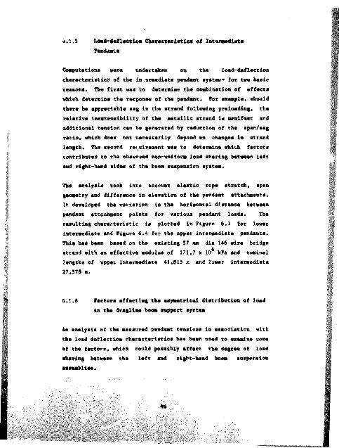
o.'-.S LoeS-4e£l*etittB Cherecteristics of Zntorwidlsto Fondaat*
Co»p«tocioas wore undortekea on the loed-doflsction oharocteristies of the tn.ateedlete pendent tyetev* for two beeic teatons. The first wes to determine the combination of effects which determine the response of the pendent. For esempie, should there be appreciable sag in the strand following preloading, the relative inextensibility of the metallic strand is manifest and additional tension can be generated by reduction of the span/sag ratio, which does not necessarily depend on changes in strand length. The second requirement was to determine which factors contributed to the observed non-uniform load sharing between left and right-hand sides of the boom suspension system.
The analysis took into account elastic rope stretch, span geometry and difference in elevation of the pendant attachments. It developed the variation in the horisontal distance between pendant attachment points for various pendant loads. The resulting characteristic is plotted in Figure 6.3 for lower intermediate and Figure 6.4 for the upper intermediate pendants. This has been based on the existing 57 am dia 1*6 wire bridge attend with an effective modulus of 171,7 x 10* kPs and nominal lengths of upper intermediate 41,815 a and lower intermediate 27,578 a.
6.1.6 Factors affecting the asymetricel distribution of load in the dragline boon support system
An analysis of the measured pendant tensions in association with the load deflection characteristics has been used to examine some of the factors, which could possibly affect the degree of load sharing between the left end right-hand boon suspension

rietic*
w * - w * W 6tieB

The aeyeetricel distribution of load, confirmed by the tests on both the upper *e<a suspension as well am the upper and lower intemediatr suspensions, is considered the result of one or more of the followsng pendant variations,
1. The difference in the distance between pendant attachment points, where the pendant ".engtha are Identical.
2. The effect of discrepancies in the preloading ofintermediate pendants.
j. The effect of differences in overall stiffness of the pendants, as a result of aomo variation in either thegeometric and or axial response of the elaeti. catenary pendant.
4. A difference in unstrained strand lengths, but with the same total distance between attachments. The compensation in strand length being accommodated by the standard take-up incorporated in the pendant preload termination.
"he resul*® of the calculations for conditions 2, 3 and 4 withtypical assumed variations in the parameters under consideration, are superimposed on Figures 6.5 ard 6.6. For both upper andlower intermediate pendants the overall stiffness, following the application of the preload tension, results in a taut flat strand. Under this condition all additional tension is generated solely by the axial extension of the strand, as the sag has been reduced to a very small value, therefore no additional resistance can be obtained by reductions in the catenary profile. In other words the overall atiffnesw of the pendant is equal to its elastic stiffness. la the example illustrated in Figure 6.6 a reduction in preload of 4 IeN is insufficient to reduce the operating point of the load-deflectien characteristic into the lower, non-linear regime of the curve. Errors produced in Mttiag prmlomd temmioM thmrmferm mmimtaim a comet ant value
*
; ;''
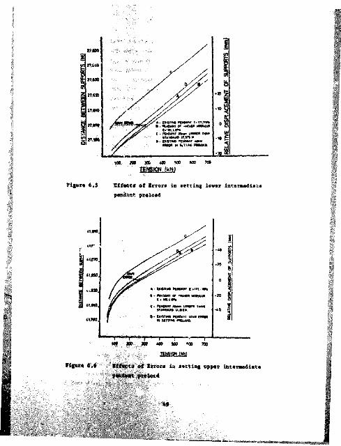
figure 6.5
m m m ms m m mm m o N ikN)
If feet* of Error* in setting lover intereediete w m & m t pteloed
' '' '

k factor considered in the stiffness snalysis wee the effect of a difference in effective aodulne between the pendants. Although this is unlikely, ss pendant sets are manufactured from the same original length of strand, collieries’ here on occasion replaced one pendant due to component failure. The analysis indicated that, for a strand with a higher i. 'ulus of about 8 percent, themaximum loads could be expected to be shout 6 percent greater,all other parameters being maintained the same.
The manufacturer’s specifications for intermediate pendant lengths are 41.815 e for the upper intermediate and 27,578 a for the lower intermediate . ith a length tolerance of ♦ 0,025 m. As can be seen from the load-deflect ion characteristic shown inFigures 6.5 and 6.6, a difference of 20 am in 1mgth between a pair of pendants can result in a relative displacement c fsupports of 8 mm for lower intermediates and 12 mm in the case of the upper strand. This variation in length will have the effect of modifying the resnective support moment arms of the boom about the boom foot pin with a consequential adjustment in their product.
The fact that the boom is not torsionally rigid can be expected to alleviate the results of the length variation, with some aide effects. Dragline booms are supported in a mannei, which attempts to eliminate or at least minimise the effect of deadweight bending. This should be achieved in the dragline bymeans of the intermediate pendants and the of upper mainpendants, which effectively segment the boom into shortermembers, theoretically producing straight boom chords, and minimising the effect of deadweight and supporting the Lending components. Should the lengths of the intermediate ropes vary, the relationship of tensions in the boom supporting strands becomes complicated due to the effect of boom deflection andresultant charge in boom centroid. This can be illustrated by perusal of Table 4.1, which details the effect of a modest change in one intermediate preload, with am equivalent length variation of twly 5 mm* resulting in a mass redistribution of load.
56

It i s b*li«v«d that this sechsni** is eainly responsible for the ilffaransas iu m s m W m load observed in %iv> loft «id right pairs of upper main pendants. The '.her main factor in the discrepancyis due to inadequate intermediate preload application andtwasureset., with resultant imbalances in the pendants.
6.2 Upper Main Suspension Pendants
6.2.1 History
Perhaps the nest critical of all tUe dragline structures is the tension path supporting the boom. The load is carried from the boom point box to che mast head by two pairs of suspensionstrands, the upper ends of which are solidly connected to thestructure of the boom pci c bo* and the lower ends by means of bronse bushed, steel fabricated equalizer links to the mast head. Each pair of strands and their associated link carry one half of the tension path load. Figure 6,7 shows the fabricated link incorporating the bronze bush. During April 19P0, « lowersuspension pendant link failed at its connection to the A frame after five years of operation. Alarmed by thus condition all other linkr were removed and inspected, and an upper main suspension link was also found to be in danger of imminent failure.
I" ' 2
Main Suspension Fabricated Link6.7

As e consequence of these failures a design review new uodertsken which esteblished thet the existing design had am inadequate fatigoe life and high oper/.tionsl stress levels. The upper main peedattta, their terrinetions m i the links a re difficult to inspect *i*"eitv* m»& removal for inspection is « time consuming operatioo. Although the manufacturer undertock a p a r t ia l redesign of the jppor main links, as a coneequence of the inspection difficulties, i t was decided to replace thesecoepon«ite a t 4-A year intenmls depwadent on operational conditions.
The periodic replacement of upper main pendants and their associated links on Bucyrus Erie 1570V draglines are majoreaiceenance icons. The purchase cast of tte componaets i* hy no means aegiigihie. and to this must he added the cost of lostproduction due to the extension in maintenance time to e fectrhsir replacement. Consequently, investigations have been undertaken to extend their operational duty by identifying the factors which cause the abnormally short lives of the components. As mentioned under Section 1.3 the initial work undertaken identified the variations in pendant tension, but was unable to find any correlation between rope length and tension ***. As a consequence of this inability, it was postulated that the cause of che error is load aha:. >g between the upper end lower pendants connected to the same link wee due to the seisure of the equalising link mechanism, which was unable to rotate to a position of equilibrium to compensate for length variations. It wee reasoned that at a certain position, dependent on the coefficient of friction in the bearing, the link ceajes to rotate with the bottom pendent spanning a greater distance than the top rope.

Yfeer etilfereace in lead sharing is apper main pendants, coaflmed in this series of tests w 4 influenced by the setting of toterswdiate pendant preloads, is in principle caused by the same factors introduced is the analysis of intermediate pendants.These are listed as follows:-
1. The difference in the distance between pendant attachment points, where the pendnat lengths are identical.
2. The effect of difference in overall stiffness,
3. Tho difference in unstrained strand lengths, but with the same total distance between the attachments.
4. An assysetricel distribution of lead in either or both upper and lower intermediate suspensions brought about by variations in preload.
J. Inadequate link rotation *e a result of seisure induced by a high coefficient of friction.
6.2.3 * Determination of Equilibrium Conditions for Upper MainSuspension System
Preliminary analysis of the measurements of pendant tension obtained from the Kleinkopje dragline test indicated a definite relationship between pendant length and tension. Thie was in contrast to ail previous work, which was unsole to determine any such relationship, and as a consequence, postulated that the Major cause ef the inadequate load sharing was due to the seizure of the link, as a result of am insufficient compensating moment to overcome friction torque.

As a result, the computer analysis detailed under Section 5.3 baa been developed to determine the conditions of equilibrium of the total upper main suspension system. To establish the conditions for equilibrium in the system requires the simultaneous determination of the horizontal and vertical components of both the upper and lower pendant catenaries and the results of their reaction on the link producing the following static balance?
f * e 8 « ^ - Hu * nyu * ^ * BXl ♦ H1 * Dy^- 6 * e * Cos p
Where?F » Resultant Tension of Link U = Coefficient of Friction R = Radius of Link Pin
\ * 7l “ Vertical components of uppir and lower pendants 6 * Horizontal components of upper and lower pendant■
e * Length of moment orm P * Angle of rotation <ȣ Link
In order to quantify the error in load sharing measured on the Kleinkopje dragline, the computer programme was used to analyse the extent of the rotation of the link under equilibrium conditions in the three load conditions:
bucket and rigging on the groundbucket empty, suspended below boom point boxbucket full, suspended below boom point box
The actual length of each rope, in this case identical, and the measured tension in the upper pendant are used as programme inputs and the remaining lower pendant tension calculated by the programme. The relationship between maximum pendant load Inferred from the computer analysis and maximum pendant load derived item strain measurements is shewn in Table 6.4. The geometric ammlimmerity of the pendant response is clearly setieeiA'le*. as the displacement of the pendant attachment
$4

iocstixm# is markediy varied by the application of load. This noGlineerity is solely geometric mod its origin may be traced to the equation given in Seetitm 5.1, namely that of geometric constraint.
Load Case
Description 1 2 3
Tens ion(kN)
Tensinn (kN)
Tension(kN)
Defined load in upper Pendant 248 471 810Calcol ted load in lower P .. .ant 325 5/8 924
Lick Equilibrium Angle (degrees) 6,67 7.46 7.60
Table 6.4 Suspension system equilibrium conditions for identical length upper main pendants <62,174 m)
The horizontal and vertical components of pendant tension are a function of the strained cable profile and »he resultant of these components obviously varies in accordance with applied load. This facet of pendant behaviour can be illustrated by considering the change in the angle of attachment of the pendent, that results between the horisontal and a tangent to the catenary ae it approaches the link attachment. Equilibrium position of the system is therefore the resultant position of the link as determined by the horisontal and vertical components of both the upper and lower pendants.
The resultant angle of the link for identical lengths of pendants varies free 6,67 degrees to 7,60 degrees for load cases I and 3 respectively. This result is achieved with a difference in poaitieeml eqmiUKium of less than 9,016 mm. thus indicating the

accuracy of the calculation*. Consideration of the information lead# to the conclusion that the resultant angle of pendant tension most always he less than the design condition of a 9,092 degree angle of the chord between the upper and lower maim pendant supports, as this is asymptote to the tension curve as illustrated in figure 6.8.
k m i m m m
figure 6.8 Losd-Link Equalisation Angle Characteristic for Upper Main Suspension
from the above, it is evident that the differences in pendant tension measured on the Kleinkopje dragline must be due primarily to the differences in distance created by the link as it rotates to a position dictated by pendant tension and catenary. At the design loads a pair of identical length pendants will result in a difference in tension of up to 114 kN. The conclusion is reached that the link design does not fulfil its intended purpose to compensate for variations in pendant length and thus equalise tensions.
6,2.4 Magnitude of Link Error factor
In order to quantify the magnitude of the error in end point locations, which would result in identical pendant tensions, computation* were undertaken using the same basic computer model fry "**## »f * revised set ef input date* The requirement wee to

•atftblirh thm aitfes«ec« ia length between » pair of upper eats fNttufti eta. which would reeu.lt in ideeticel ten*ion* under efBilihriue condition#.
The total suspended lead per side xer each load condition, established is the tests os the Kleinkopje dragline, ess used to determine the individual, e^ai. pendant tensions in the programme. The upper pendant of the pair at the manufacturer's design length, as sell as the derived coefficient of friction from the first exercise, were selected as the remaining specified inputs. The computer model was then seed to determine the lower pendant length commensurate with the specified values.
Table 6.5 shows the results for all load conditions and establishes that the magnitude of error due to lin k rotation is between 28 mm and 16 mm for load eases 1 and 9 respectively.
Description
Load Case
I 2 3
tension Length kN N
Tension Length kM M
Tension Length kM M
Upper Pendant Lower Pendent
307 62,174 307 62.146
544 62.174344 62,154
908 62,174 908 62.158
Link Equilibrium Angle (degrees)
5.11 6,27 6,80
Table 6.5 Different... in Pendant lengths necessary to result in e<fual pendent tensions under equilibrium conditions
The results show that the difference in length between a pair ef pendants, to asintein equal tension, does not remain constant
oughout the eperetSeg range.

6.2.5 Consideration o£ Friction Coe*tx-iett
It is difficult to define- those factors that govern the action offrictional forces, which effect .he li mechanism. Severaltype* of friction may play a part and they are described brieflybefore discussing the® in detail.
(a} Dry* static
This type of friction results when the contracting surfaces arefree of contaminating films - oxide, moisture, etc.
Cb) Boundary; static
This condition of friction results? from heavy loadings at slow rotational speud even when a lubricant is present. The surface'a r e not in intimate contact, but are s e p a r a t e d by a filmlubricant.
Cc) Semifluid or mixed friction
This kind of friction results mbeo there are incomplete orpartial fluid files. The situation develops when the rubbing surfaces are separated partly by viscous films and partly byareas o. boundary lubrication.
These factors represent part of the complex picture of surfaces in contact. Fuller ^ in his book. Theory and Practice of Lubrication for £i ineers, discussed how specimens that wereclean and free of o4ly contamination, but were imposed to atmeapl.eric air, showed # coefficient of static friction of 0,39. When the specimens were lubricated, the coefficient of static friction fell as low as 0,11. In general the factors ~hat imflmemee dry friction also directly effect boundary friction.
a#

The relationship for dry/boundary friction on the friction force can be considered as follows:
1. Is directly proportional to load.2. Is independent of the gross a-ea of the contacting surfaces.3. Depends on the nature of the s .iding surfaces.4. Is influenced by other vaiisbles, such as surface roughness,
vibration, etc.
Walking draglines are self-propelled machines powered by largeonboard mutor-generator sets. These units together with otherequipmen*-, such as air compressors and ventilation fans, produce vibrational disturbances, even while the dragline is stationary. This is aggravated by vibration of the boom (induced either by impact as the bucket is released or retrieved, or by drag rope variations) and is --onsjdered to influence the coefficient of friction. The effect of this can be illustrated by the normal practice of tapping pressure gauges and barometers to decrease ihe friction of the links and increase toe sensitivity and accuracy of the instrument reading.
However, when smooth surfaces are held in tight contact ,nd subjected to slight vibratory motion, some degree of frett ng corrosion is possible. This can be minimised by the presence of a lubricant. The bronze on rteel configuration of the journal bearing is lubricated by the man"... 1 application of grease at some specified maintenance interval and is thus not infallible. Bushing cleanliness also cannot be taken for granted, due to the dusty operating environment of the dragline.
As a result of these factors the estimation of a static friction coefficient, suitable for .his application from the typical values of published friction coefficients, is considered unreliable. In this investigation, in order to probe further intc the influence of the link on the equilibrium conditions of the pendant assembly, a low value of friction coefficient has been used. Th:« has the effect of minimising the friction force
59

on the link, and In terms cf the digree of pendant lead sharing, can be considered to be a conservative approach.
The effect of variations in the friction coefficient of the link bashing and their influence in the degree of pendant load sharing is illustrated in Figme 6.9. Tie analysis was determined by using the computer model in respett of the boom only condition (load care 1) for both equal length and equal tension upper main suspension pent ai.ts. It confirms that a.t increase in the friction coefficient results in an increasing linear response in the range of the pendant load sharing.
60 100 160 ZOODIFFERENCE IN PENCANT TENSIONS (kN)
Figure 6.9 Friction - Tension ' haracterist..c for the Link Assembly with idenrical length Upper Main Suspension Pendants for Load Case 1.
The analysis further indicates that a friction coefficient of 0,26 is necessary t.r result in corresponding values of pendant tension between the calculated tensions, as determined by the computet model, and the tensions, as measured on the Kleinkopje draglinu. It is therefore concluded that the type of friction existing between the contact faces of the link bearing, during the duration of the measurements, was generally dry,or possibly with come sux faces in intimate contact, and the remainder separated by an area of boundary lubrication.
60

7 CONCLUSIONS AND RSCOM3NDATIONS
7.2 C<HBicl»sioa» free Zaveatigatioa
A amber ef conclusions end recoaaendction* have been formulated from the etmdy of ttw dragline bom suspension, toremoet #.&#% substantial iabalancas in load sharing occur between the toy and bottom pendants on each side ef the dragline under static and dynamic load conditions. This is due te the fails** *f the equalising link to fulfil its intended purpose of egMdMdieg pendant tension due to the inherent effects of the basic link geometry.
The search for a solution, which would satisfy the constraints identified in the investigation, but it the same time yield acceptable isprc ament# in drag ne design, tegulrad consideration of the following goals.
Lisdt variations in pendant tension.Seduce the effects of variations in the friction coefficient.Ease inspection requirements.Produce a simple robust design.Improve dragline operational availability.Seduce coots.
All of the local Bucyrus trie draglines, and a substantial member in the dnited Stat-a, use the same basic link geimetry, betb m the upper and lower we in suspe xott systems.
61
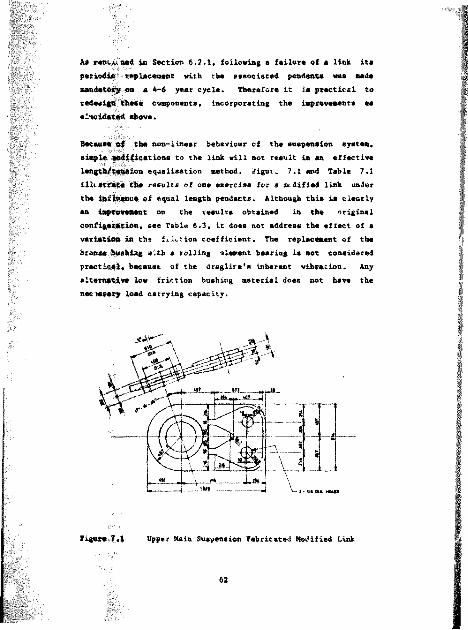
As nMRiMtMrfl Is Section 6.2.1, following e failure of • link it# periodic replacement with the associated pendant# was made mandatory on a 4-6 year cycle. Therefore it is practical to redeetgtt these components, incorporating the improvements aselucidated above.
' .Because ©f the non-linear behaviour ef the suspension system, simple ipsdifications to the link will not result in an effective leagtfc/teiMlioa equalisation method, /igut^ 7.1 e»d Table 7.1illtstrete the results of one exercise for a atdified link under the imf%h#mce ©f equal length pendants. Although this is clearly an iapfevemsmt on the results obtained in the original eoafigssstlon, see Table 6.3, it does not address the effect of a variation in the f.lotion coefficient. The replacement of the bronse hushing with a rolling element bearing is not considered practise!, because of the draglire's inherent vibration. Any alternative low friction bushing material does not have the neetssaty load carrying capacity.
figure 7,1 Upper Main Suspension fabricated Modified Link
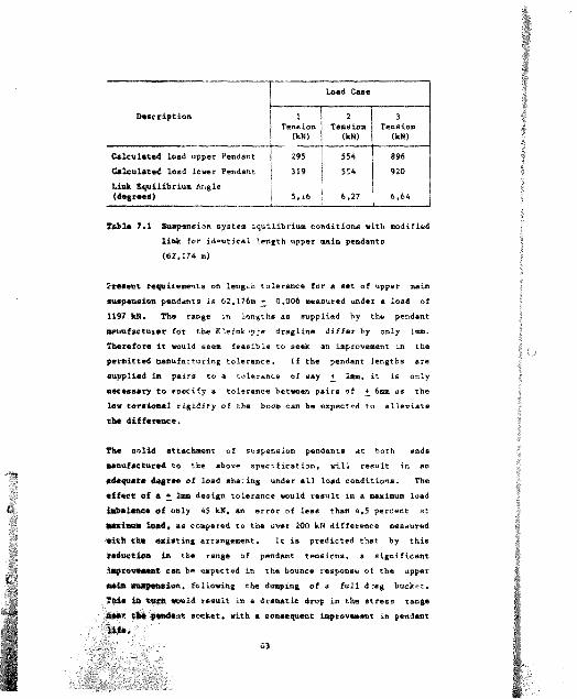
Load Case
Description 1
(kM)
2Tension
(kN)
3
(kN)
Calculated load upper Pendant 295 554 896Calculated load lower Pendant 319 554 920Link Equilibrium Angle (degrees) 5, j.6 6,27 6,64
Tsfcls 7.1 Suspension system equilibrium conditions with modifiedlink for identical length upper main pendants<62,174 m)
Present requirements on length tolerance for a set of upper main suspension pendants is 62,176m _♦ 0,006 measured under a load of1197 kJN. The range in lengths as supplied hy the pendant ■euufactuisr for the Kleink jpje dragline differ by only 1mm. Therefore it would seem feasible to seek an improvement in the permitted manufacturing tolerance. If the pendant lengths are supplied in pairs to a tolerance of say + 2mm, it is onlynecessary to specify a tolerance between pairs of +_ 6mm as the lew torsional rigidity of the boom can be expected to alleviate the difference.
The solid attachment of suspension pendants at both ends manufactured to the above specification, will result in an adequate degree of load sharing under all load conditions. The effect of a 2 2mm design tolerance would result in a maximum load la&alemce of only 45 kN, an error of less than 4,5 percent at w m i m m lead, as compared to the over 200 kN difference measured with the satiating arrangement. It is predicted that by this reduction in the range of pendant tensions, a significant iepreweeemt can be expected in the bounce response of the upper meia ewyemelon, following the dumping of a full d rag bucket. This in turet would result in a dramatic drop in the stress range ###* *1* #e*de*t socket, with a consequent improvement in pendant

In the event of the pendant manufacturer not being able to meet the recommended length specification on a regular basis, a minor modification to the fiat >d attachment could alleviate the problem. Pendant lengths are determined prior to installation as a result of the verification exercise undertaken by the manufacturer in che tensioning frcae. The verification was described in Section 3.3, Manufacture of Pendants. A locking type of ecctratric bush can be designed into* the fixed attachment point for one of the pendants to compensate for minor length variations.
A second conclusion reached is the inadequacy of the setting of intermediate pendant preloads. The manufacturer's procedure for the static tensioning of intermediate preloaos requires the simultaneous operation of four sets of independent hydraulic tensioning jacks, using pressure gauged with non-direct reading scales. Small imbalances in the setting of these critical preloads fcr both leit and right and upper and lower pendants can result in significant shifts in the reactions of the components of the boom suspension system.
It is therefore recommended that the jacking cylinders for left and tight hand pendants be hydraulically interconnected, so that both pendant tension# can be set simultaneously. The resulting hydraulic pressurising equipment for both the upper and lower intermediate pendanti? should be so positioned as to evaluate their combined effects.
Finally, it is considered that the stiffness of the main and intermediate suspension pendanta should be matched, so that increase* in load are proportionally shared between them, so that the reactions due to the centrifugal forcea are correctlydistributed.

7.2 RftcowHrod*tions £01: future Investigation
The pressure gauges provided for the tensioning procedure ere considered incapable of being used to set the required preloads to a sufficient degree of accuracy due to a number of ftctcts. Some confusion results from the necessity to double the pressure gauge reading to obtain the pendant preload. Furthermore, in the event of ovevpreseurisation, the gauge reading was found inaccurate due to seizure resulting from friction of the preloading bolts on the socket bridge piece. It is recommended that a strain gauge method be developed for determining and monitoring pendant loads during tensioning.
In view of the importance of correct tensioning of intermediate pendant preloads, e effect of variations in pendant length andtheir significance should be determined. The present specification calls for the penda.it to be manufactured to a tolerance of + 25am and as discuss* in Section 6.1.6, due to the low level of torsional rigidity of the boom, the consequences of the liberal tolerance should b«_ examined.
Finally it is recommended that the conclusions reached in this investigation and the data obtained should be used to refine the boom finite model and their consequential effect on structural integrity analysed.

A f f O D I I A
SFEcmcATicm or iMT»UME*rs usmo
#6

Afpnma A
S: tCIPICATIO* OF I K S T K U M M r S D M D
Portabl# Strain Indicator Modal P-3500
Manufacturer
Sanaitivity Bridge Emritation Calibration
Analog Output Power Supply Size and Weight
MEASUREMENTS CROUP. INC. USA + 19 999 y*
^ 3 y#+ 1 Y*2,0 VdcShunt calibration acroaa 120n
350A dummy gmugea to simulate 5000 Linear +_ 2,50 V mam Internal battery pack 228 * 152 * 152 :* 2,9 Kg
Deacription
The model P-3500 Strain Indicator ia a portable batterypowered inatrument for uae in at ream analyeia teating and (or uae with atraia-gauged baaed tranaducerj. Itincorporatea a highly atablm DC amplifier regulated bridge emcitatioa nupply and aettable gauge factor control#.
Static measuravanta ^re read d.recti) from the LCD readout with I p. remol'ittun. An analog output with * - 3dSbandwidth of 4 kKa ia provided to diive an external oacilloar oe or reccrAer fcr dyn&mic meaaurementa. The inatromen will accept full-, naif-, or quarter- bridgestrain gauge inputa.
B.idge excitation ia 2 W c , reaulting ir low gauge pome* and
negligible drift dm# to gmmge a#lf-h#ating. Cmuge factor ia
precisely aettahl# b y # front ^amel 10-turn poteotiometer to
a rooolution of 0,001 m a i t * and is diaplaymd om thw LCD
#7

readout. when the gauge factor push button i* depressed.
Switch and Balance Unit Model SB-10
Manufacturer MEASXmEMEH/'S GRO’JP, INC. ;?SACircuits 10 ChannelsInputs Mill accept quarter-, half-,
or full bridge circuits in any combination
Balance Range * 2000 p «Switching Repeatability Better than 1 pt for g*uge
resistance of 120a or higher Sim# and Weight 230 * 150 * 150 mm. 2.5 Kg
Description
The SB-10 Switch and Balance Unit provides a means for strain measurement when more than one strain gauge is involved, It is designed for use primarily with the P-3500 Strain Indicator and features gold-plated push/clamp binding posts to allow fast rod reliable connections of in^ut circuits. Individual ten-turn locking potentiometers with turns counting iials are used tor fine balance adjustment. The channel selector switch has negligible switch resistance.
3. Strain Gauge Type
Manufacturer
MaterialTemperature Range Gauge Length
TOKYO 90KKI KEMY0J0 CO.. LTDJAP AHCu-Wi Toilo-#o*c

Gau&# Width 7.7 mmBw# 23 * 21 mmNomiaml RmmimtmDc* 120 + 0,3 ftG#m# fmctor 2,1
Dmmcriptio*
Thm gang# ha# & two #lm*#ot 90^ "t*#" mtmckmd ro##tt#coafigwratioo mad baa b##o to olimimat# # moiatur#proof comtiag. On# matt# long l*ad one *ir## arm attached aod th# whola mr#m of tha gaoga and junctiom of tha l#ad aira# ovarcoatad with # tranaparamt flamibla apomy raaim of approa. la* thicknaam.
A cyamo-acrylata adhaaiv# waa uaad to bond tha gaaga to tha pandant *ockat.

CAUMATIOW 0* BOCOTS
70

dppm m n i
J A L I K U T I O W O F S O C M T S
In o d*r to evalumte th# d#gr«* of lo#d equaliwtior d(#glim#
upper main muwpeomior. pendant* &ud th# #ff#ct int#rm#diate pendant preload# hav# on %b#*, th# pendant iexJ# %#ere meaeured by attaching attain gauge# to their ^ot^wta.
The attain gruge# were arranged and attached to eearu.* i
atrain and to compenaate for bending ef *ct# em illnalri:'j .i
Figure 4.2
D e t e r m i n e _ion of B r i d g e F a c t o r
i4 213 E
2(& + 1) + 2(B~- 0.3 7) 4R + 1.4 K
" ^4231 % 2» __ :_____ 2(R » R)
4» * 1. 4 P2KR 2% »
" 4 » + 1. 4 &
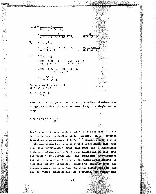
2(k - 0,3 Rj 4 2(F * R) « 4R ♦ 1,4 R
2(R - 0.3 R)4R +1,4 R = 4R * i.
= 2ER - 0.6E R - 2ER + 2E R4K + 1,4 R 4R 4. .4 -
* 2RR - 0.6E - 2Ef - 2% R4R"+ 1.4 R
" - R
For very small values of R 41 + l.A * " 2R
So that 2,6E R 4R
Thus the eull bridge connection has the effecc ©f W*i«g the bridge sensitivity 2,6 times the sensitivity of a siagls active iauge.
Single gauge = ♦_ E R4R
Due to a lack of rpare draglir.e sockets it ha# nut, %##B p* a&ible to verify the calculated load. However, ia B ft«vi©us inveetigation undertaken by D.R. Fry ^ slightly Socketsby th« same manufacturer were calibrated in the ftaggi# IbUld Test rig. This investigation found that there was s leantdifferer e between the load/atraij calibration and # # $m& item the stress * are* calculation. Th# calculation the load by as much as 74 percent. The design OS isFucn that the uae of nominal stresses to *mdobviously does, lead to errors, the author OSSted that thia ms due to stress concentration aad gradients, as clearly this

depends on i aometry end eK'pe of the socket. Designs, which have long lugs etwee* the eyes and the socket basket, will give a closer correlation between calculated and actual load, than designs h have short lugs without a reasonable length of uniform cross section. The figure shows uchesetic sockets and illustrates why the strain measured could lead to inaccurate over-estimates of load.
The dimension of the lugs used in the calibration exercise are 208 * 77 am against the 184 * 67 mm of the Kleinkopje sockets. In view of this similarity and the socket geometry, it was decided to factor calculated pendant loads on the basis of the calibration exercise to compensate for tension gradient etrorr. This resulted in s derived gauge factor of 4,49. It oust also be noted that the requirements of pendant tension of this investigation are basically of a comparative nature and thus are considered to be relevant despite any tension calibration irregularities.
rNON UNIFORM STRESS DISTRIBUTION
SHORT ARM
LONG ARM
UNIFORM STRESS DISTRIBUTION

KLEINKOPJE BUCYSOS ERIE DStAOJNB UPPER MAIN SUSPXHSIONmmAffl LOAD MEASUREMENTS AT T H MANUFACTURERS SPECIFIED INTERMEDIATE PENDANT PRELOADS
Microstrsiti
Socket Bucket os Ground,, Empty Bucket, full Bucket
1. Left top 250 449 763
2. Left Bottom 379 622 9353 . Right Top 214 407 7014 . Right Bottom 320 551 870
Pendant Load (kN)
Calc. Derived Calc. Derive 1 Calc. Derived1. Left Top 499 290 896 519 1522 8822 . Lsft Bottom 756 438 1241 719 1865 10823 , Right Top 427 248 1312 471 1398 8104 . Right Bottom 638 366 1099 3:7 1736 1006
Difference in Pendent Tension CkN)
Between 1 S 2 257 14# 345 200 343 200
Bet**** 3 & 4 211 11* 2*7 166 338 1*6
Note
The calculates ' mn load Is derived from a bridge factor of 2,6 and the derived pendant load is determined from the previous calibration results.
74

Appnmix c
E&LE RESULTS OF COMPUTER A3&LYSI3 INCLUDING EmmOR A W :ia
75
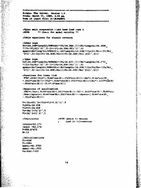
* » *Mi## 1.0M # * " w * n , w#». :iw #«. mm# of *#»* ai*, *«\K#mmn###*##**######****#*###**###***»**###******#*******************
j Upper wutin suspension right hand load ease l t m m ** OmcK for acdel validity •*
? Cable expiations for elastic catemurY
i Lower ropehi- (24.208*lengthl/698420) * m / 2 4 , M#- .5)4. (HI »le»gthl/24.208)*m+ivi/Bir2r.s-ci+c(vi-24.2oe)/iiir2)-.s)■peal-melang^hl/69S420)♦ i (ai*lenrda/24.20S>«(ln(Vl/Hl*( (Vl/Bl) '2*1)‘.5)-lai (Vl-24.208)/«!♦ ((fVl-24.208)/Hi) '2*1) *.5))}liiMNr tof«ha* (24.208*l«ng fehu/f f8420) * (Vti/ 24.208-. 5) + (Hu* leagthu/24.2 8) *((%+(v*/*sr2r.*-;i+((va-24.ao#)/Bur2r.s)^aau* (to*lengthu/69e420) ♦ ((Hu*lengthu/24.208) * (InCVu/Hu* ((Vu/toi) "2U)*.5)-ln{<Vti-24.208)/»i-f{{(Vu-24.208)/Hu)-2-H)".5)))
.•Equations for lower linkF»**.203-( mi2* (. 91*4*30# (I)-.2023*sin(8>)) - (Ha* (.93 44*sin(l)♦ .2023*coe(S) ) )+(V12* (.S144*cos(I)♦.3023*sin(B))) ♦(HI* {.2023*cos(I)- - 9l44*sln (IHMS.O*. 6*oos (K)))
; Equations of equalisation.3997«((hu*(.9144*sin(l)*.2023*cos(En)-(hl-(.2023*oos(E)-.9144*sin.0*4«{(ep<ml*(.9144*ooe(E)4.2023*sin(E)))-(spanu*(.9144»oos(B)-.2023*sin(E))))
r» ((Hu*Hl) "2* (VU2+V12+S.0) "2) ‘.5 W2«ma-24.2QS V12W1-24.208 T@e(ma"2*va":)-.sT1*(H1’2+V1‘2)‘.5
;Constraints
lengthu«62.174 l#o#tk *W.1?4F-606.87673*#.12
fInitialisations Tu !*248 Tl,"3#0spaaui»61.3700 spaali**61.3935Bu:-242.fUC2
I NOTE Length in metres i Load in kilonewtons
76

Eurekai The Solver# Version 1.0 Friday March 31, 1*#$, 2,5# p*. Warn* of iaput file: a,\#rfE3PTl* * * * * * * * * * * * * * * * * * * * * * * * * *
Mlx-35#.l#a8Vbi#S1.4W471,-70.3*26hu>*.#sahi>#.#sa
Eolations
Variable#
Er
hi
MlHU
bu
lengthl
lengthu
M
epaml
epmno
T1
TU
VI
VIZ
VU
v*a
Value#
.119 066 2660 6 . 6 7 6 7 39. 9 5 4 0 3 S 434 1 . 0 9 9 6 62 6 0. 666 769. 9 5 1 9 9 9 661 . 1 7 4 0 0 06 2 . 1 7 4 0 0 0 .12000000 61 . 3 9 0 6 2 9 61 . 3 7 4 6 6 9 34 7 . 7 0 1 3 9 2 6 6 . 3 1 5 2 # 6 7 43 33 #) 4 3 2 2 5 ^ 3
54 40 46 46 30.1
77
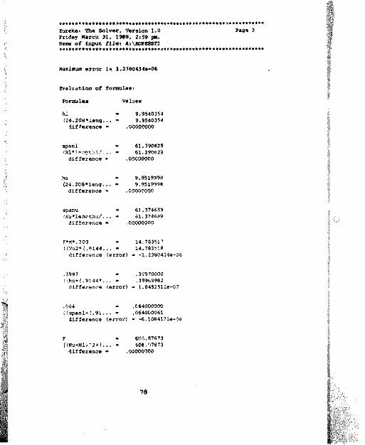
Eurekat The Sotwr, Version 1,0 Wmgm 3Friday WmrtA 31, 1*##, 2,5# **.Saw of input filei SiXiKSMBOTTl
Maxima error ia 1.2380434e-06
Evaluation of fozeulaa$
Ponmlas valueshi(24.20W*lang...difference •
*.#540354#.#540354
00000000
spaal
difference
#1.3#042#61.3#062#
00000000
hu(24.20#*leng.difference
#.#31###*#.#51####
00000000
spanu(Hc'lengthu/...difference -
6].3746## 61.37463#
00000000
r*M*.203((Vu2*(.?144... -difference (error)
14.7#351?14.7#351#
- -1.23#0434e-C6
.3##7 - .39#70000(\hu*f.#l44*... - 3##6###2difference (error) * 1.#452512e-0l
064 - 064000000((«pmnl+(.#i... - .064000061difference (error) « -6.10#4172e-0*
F " #04.#7673fmTu*#l)-3+(... " 606.W673diffaraooa - 00000000
?*

tirmka: thm Solver, version 1.0 Page 4Friday March 31, 1*#, 2,3# pm.Mmme of Input files A:\ROP2SBTl -
" 30.1#[email protected] » 30.1#W4#diff#rano# « .00000000
V12 * 43.2253*3Vl-24.20# - 43.2333#3differ#«c# - 00000000
fa » 2*4 3052#(ma'2+Va-2)-... * 266 052#differance » .00000000
T1 " 347.701:#(Hl"2*Vl-2)"... " 347.7013#differenc " .00000000
lengtha62.174differenc#
62.37400062.174000
00000000
lengthl62.174difference
62.17400062.174J00
.00000000
F - 606.6767]606.87673 * 606.87673difference " .00000000
M - . 1200^*0012 " 12000000difference - .00000000
Tu ^ 66.30528T1 » J47.7013#spenu ^ 61.3746###p#al - 61 3#062#Hu * 360 6##78Ml " 341.0##6#Vt # 54.404646
9

%UT#ka: A # *olv#r, V#r#ioo 1.0 ?#*# 3Friday Ward: 31, 19#9, 2:59 pm. mam# of laput fila, A:\moMsmri
VI - #7.4333#)
hu * 9.951999#9.952 - 9 9520000dlffarooc# (arror) » -l.#4#9033e-07
hi - 9.95403549.952 - 9.9520000diff#r#nc# - .0020354247
Maximum #rror 1# 1.23*0434#-06

*imswc&5
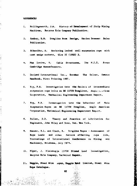
REFERENCES
1. Hollingsworth, J.A. History of D#ml»9##nt of Strip Mining Machines, Bocyrus Erie Co^any Pufclication.
2. Satikey, B.H. Dragline Boo* Deal#*, Marion Dresser Sales Publication.
3. Schneider, A. Anchoring locked coil suspension rope with cast wedge sockets. Wire 35 (1985) 3.
4. Max Irvine, H. Cable Structures, The H.I.T. Press Cambridge Massachusetts.
5. Borland International Inc., Eureka: The Solver, OwnersHandbook, first Printing 1987.
6. fry, P.R. Investigation into the failure of intermediate suspension rope bolts on BE 1570H Draglines, Anglo A,tic an Corporation, Mechanical Engineeriag Department Report.
7. fry, P.R. Investigation into tha behaviour of Ms in Suspension Ropes on EE 1570H Dragline, Anglo American Corporation, Mechanical Engineering Department Report.
8. Fuller, D.D. Theory and Practice of Lubrication for Engineers, John Wiley and Sons, Inc. Mew York.
9. Manser, B.L. and Clark. R. Dngline Ropes - Assessment of Rope Loads and other factors affecting rope life. Proceedings of International Conference on Mining and Machinery, Brisbsne, July 1979.
10. Piper, J. Kleinkopje 1570W Straad Load Investigation, Ineynts Erie Coapaay, Technical fc^ert.
11. Haggle, Steel Wire .«opes. Haggle Rand Limited, Steel Wire Rope Catalogue,
#2

Al'bENDUX m TI!E k!:rORT
HuCVKI/S I.KIk lj/Uk -
A%A:.YS;< Ur ilX'FR XA:::
sr:'pK:.Y,ios sYsr^.
.lll&Xll'lr/) I\ r!::':'nr.r-i: .i- T!il
y\:/-:XP/' - M:. KT.

l T i v , o f Chlm u r c f r r c m i t o p r c / r e ' i s n i : i ' i ( . " - ; i : y !)v
p r ^ v . f l l l n ^ c i r c i ^ i s : H : i r r K , P f i dom i a i t p i - s m t h l ' ' m . ' . / r i . ' p j t c . f
p r r r ^ r h n c i n a t n ! n l l v and v : : ,T ^ , l u :
I n ^ l f i n r p , The rh e o u l p u r -'T I 'mrh - : " . i
CMn be iin'1,.T t . i l : ( :n ' . ' I l o w j r r ' t < m a n u ( a r : L r ' . .
n« ' ;,i ., , f t he: r < > :. » , 1 i rf. prr":,'!-:
r r r n r f ' (4 .H 'ru^K '-Lir. T n s r ^ l i . i l x n :
''CiiLinrs i-'ir 't .rUr*' -! vith r.ir-. r.!%rr
rh. ' : i r - : - cn ! ' i - . . r.\. . [ ' i' wi- !
;,r. I , T ri:
T u r I ' " T I H r r i i " . ; ix 1 m e . t : / c r !
. i ; - ' : : . " ; i r y n v i ' r ' - ' ' ; ' ' ' n st
.i-y ." T ! i x i r i ' s r n : . ] - : - ; - C i o n T r ; ' r
nrir:;: hi'ir;; icnl' ' ' [{.nr.
I ' r / i . l i n - .1: 1- .t: " - ( : r ! ir , R r v . . r V . . ' T '
fr.vr) : , thr sjrc ; i c: :T : ., ' -
i c u s f l r r i t l o n s r . 7 ' ' i r ( ' \ p ro du c t ; f : - . ; , : ) ( v " I : " "
( » r h , p s le w c t H t i s l i c ' . ra : ! i z ; i l ' ! y t h i s
.^ r r t ' : ' l . x id b a ^ rd . m o b i l e m w c h ln m ev.- ; ! ! r .i." . : .s
K r i r k D fM K l i n * ' 4 fiOO C nnd r r p r e s r i i : . - ' n ,1 : f r f of
70 ('00 U00. I t o p fT ^ te H on a 24 h o u r d a y , 7 w rvk And
s iopm ou a v e r a g e t n r o n l y f o u r d a y * !n rui* y * ; i r .

y - j i n r . ' - j n r ? iA x; : . ( !er r ; i ken i , o n f pfiC: v c y c l e u s u a l l y of 10-12
Ilnurs. U;irlnt{ tlie^e prriwJs buckf: and running -'p' replacmment
h r i P t - r d r ; /ip r i ' p e s ) i s c t r c n u n d o r r . i k e n . Each au*p*n*lon
P'-mlAr: c.:irs R 90 000 suipenHlrn link K 85 00J, these are
r^-pJaccd a: r'.-''"ds rot n'lrr.i 1 ] \ ey-ckniuR i! c \ e a r s . To replac#
r!.e:.e rnzpf)r.H.;rs (ik'-:. 10 il^ys. r,pfesi!t.ir!n^ the lowering of the boom
d mu'.' ,i r 'f-'' r t - c , : ^/cr .. 2 -'00 0y.
- \-'ui. Tx.':,;\.: r.'/Kr ki.si'wrxTf:.
: . .I r . t : I : " ' c . ' f r ' . r : : .v ( . ' f - L . t x ' ^ p r n t r d f i r e 15/0W
' .u.' 'rn,HL,% i'UT. ..H':; N due to
- ! , i ' i ( r ^ f ' p ' 1: : - . - - ;i I ,:% 1 e in d a« a
^ r y- . ;'.i r <' T 1 - - : ; : n. f : r ,i i . 1: i j n o t
: t . ' : . i . . ,s ! «'..4 T . . : . r c. . - - m r r ' . H ' ' n t s . t h e y a re
.. -T . i f . y r : - . r c i l v c r y f u p r u v l d e
- ' . . . ur-r^rln^ pend.mlF
: ' . r - - - ' ' .,v ;i: . . = r i r . T. . u i i h f o r ( ! f i" f n r t h e
: ' . i r u , : , .:<i ^ . - s u .u ' i l n f ^he
. : - , ' ' I ' i - . k . - r ' , ' p , 'n ( :antR were
.v i j I : I,- t .< c r \ : . . r r r [ ' . »! ' i r^i 1 ] A t lo o and
' r i- r !i . i I it ' r " i . l T ' . ^ ,! ! i ' : v . X" i f ; r«vi«'n r ! \ « r A sE ra i n
ky::KC .i . i l v J-: ! i : i ! ! " ^ r i / y , r l r i ' - f ^ r r c / i ] i h i a c i & m
: X i'V . : irr:.' t : :; u ^ - nr vt t :. ; i ir l r ',
/ / (h«: ( I r e i l , . h r \ ' . i l c(" p p r id an ta was
- t i l l i n l t % i T i f n i K " . . - i u i f l r T ) / , ( h r h r . i l o f g ^ c k e t e was
hi [rn;r*_,*. . im *./,( kef y wure iv.M 'inhle al the Cine, thm

Inpurtatlnn o:" m met of pocket; waa nece##«ry
deJlvmry. Thes? socket' were supplied by a arU
tliffmred in phv ./a: dimensjcns fro* thoa# pravl###) l # d oo
group urixilnes- Sock*?c; from d:fcmrded pwlamta fMm'Wtb fcthlaham
Stp*l ond US Stctj vere ..vailable, but following fAllt/# th&
vse of secondhand sockets was uoc penmimmlbla. A# #&&_#&# E#co
No^kecs wtre us^d nn tiir kleinkopje inatallmti**, #» *#%lbTmtion
exercise fullowing chlm rouff wap poselbla.
The eK,j%jner h.if, posr ulntard rallbratioo A * D*od*nLa,
M.c cccpii'niq aif -.tHI in service aod wi l l # 0 f^r a
number /K.rs t !s ;ilter i.iilvp 's iot pracilcal Co rmatlt#
uj.;lfr iH'rmnl oppi r!nr!."i: rlr^u^ tmncet.
pr--. r'i s.x-xrti lur rhc inskallatloi. ktain gaugca
.s o-i: - , ' i! r . i i . 1 ] 'wr:^ ; -pi r ^n^ fal laf on Ch# er#d boom,
i w. f; r - l'' sr': 'i t-he raft su'faCd# of tk# #»ekata to a
fl\!sh .,1 n,r n i u n r,r :^a acradn **####, Th# cror-
riu.,n. .f rhf lups L i uiad tu # # t a b l i # k t b # cantre
l:r-pf f v the r.-i-, t locfLl-,:: u. Clw ^ a ^ e m . T h # M a f t # T * tb# gauger
wrrp L.. to csc^hl.ghed datw m a , CTW # -# *Ction#i
art" IS did n.K v.ir v hy rrM- i ;'M(.enC t:i Ch* lug# fiCt## « l t b atrain
y. uRes.
,Tio\ n}- A};,\.YT:':AL wiTH EXPUmfrNTAi __ .
ulrpuk'nt (.i establish acad*p#c l u va lm r f #*$**#$?
iid si.aln co fnrca 1m Con#i^*W;,^|#0##*e#riAta.
; vith the leval of arcm
of within 10-15 pe cent of akaoluta v a l w m .
Thfa la tuwmwom iraco vith the :eval of arcmrmcy c W # d la th# T##ort

"he repeat of tea. aent# takan or mobile equipucn: operarin*,
an uneven -at -1 murf»cas la Co ao## a%cant uncertain A-id ijn lur theme
condition# ou accuracy to within 10 p#r cant oJ #bsoJur«t vaijf ; c^n bp
c r ju s td p re d to ba good.
Practical methods have the ability to esiabllsh r - n d a n r whjrh
can he usfi to aaaesm engineering acructures pr.nlu&i c.i-u jn t u I
fm;)rovementa commansur.ite with tha available t ae an J rust .
i ' r e l ( r fn m r y w o rk '«n t i l l s in v t m t ig a t lo n in v o lv e d t - » J - r rTnir-.ic im i . ' f
t l ie r p s u l t a n t moment a b o u t th a boom fo n t p in e ? r T !.p . . h e r <.f
,;p c io n m . Fo 11 u w in g ch.? d a ta rm fn J t (on ;»f The n ' ' - t r . i j n ,
: vfis Immediately obvious that p#odanL tenmlnn (ir; i vc .1 : i s t r e s s
An:,i c;i]rulaticn w/if: significantly inarcur'.u?, w!:uri ' »7, w!:h
rh.' r- levant reyultmrl :mompnt calculation. Thfs r;m hv : -( - ' r r.! .im
1 ,) j I ,:W5 :
i''i< * ( i un r he bucket nn rhe ground with the f; . ',n\. h.n ;i .:u"n h I xk
pI ;hr ,»rf fhe hoist rnp*'M. The bucket should I;*' iv,i: . - - : .1 i i ;»i [ v
h« boom point Hh^avem equivalent ri' aiTlmuc- ir.,: . -.tu:,! .i
n s m i n .fugf rcadlnx*;. Thia poaitinn is .
! .
A fuither ret atrain menmurementa 1* emtAbllshfil w!t!, ... .
Tiurkei hoisted at maxfkum reach to a position jeft !i.- Nr
trfp-ont point. Thi# pomitiun r*pr###ntm load cn^n
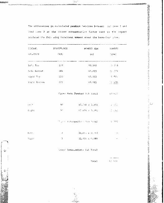
The differtLC## In chlculakmd p#ad«nC -*n*ion» between oa-i case 1 ard
load caae 2 mt the stream conceatraticn factor uaed In the report
produced th* fol* wing resultaml moment about the boom-foor pins.
rLKDAN"! DIFFERENCE MOMENT ARM MOMENT
LOCATION (kN) (m) fkSm)
Le^c Top
Lfft Bottom
Top
Klglit. Bnftnm
279
2812:3
271
40.465
40.465
40.465
40,&65
0 2' 6
II 371
Cppcr Main Pendant Suh Total
'.O 42,256 x 0,94542.464 x 0.1O5
Inreroedla Tnfa]
(; 32,00.'* x n, )890 32,004 x 0,989
Ixwer Inteiwediai^ 5uh Tntal
Total
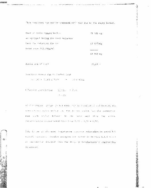
r M s rgyuifant can now be compared wi^h that due Co ch# empty bucket.
Mass o f f u l l y r ig g e d b u c k ^ c 72 "L59 Kg
a * e q u ip p e d d u r in g th a te u c s c ru e n c e
I.e fa che - e d u c t io n due to (5 477)K g
hoiwc rope (6 j,5 6 K g /m ) ___67 382 Kg
Xum^:ir Arm o f I , ,. id 75 ,6 8 '
' 'c ju l f . n .T M rn u r l dun t ' l .u r k p f ln ;u l
\ x
' ' f / c . ( : v c L C ir r u ^ / i l jo n h j ] -
1: I'.:'- muir.i: :,i. uati .% l. d bc».i ,ix a zfLlial u: the
-tt.i'' '"'ifi- h;,' .u: [he :;.,kc[ Tu?) tlif nsmumprjun
i ' , . h r '< , [ h '-h -iv r- ! In '.h^ * . iy ) t h r u th e x t f r ; : .
. x x f ' - r . K t f t ' i i k o u N h iv - l. -o n : ,7 J . - i , " ) / .
T h fp i : mn o ! ( h'- many ( .'m pw ra t Iv e i ^ c r r i n p u n d e r ta k e n t n c :« tn h ] js ^
u v c r iX iL 'iX iii:< y . F u r t h r r r x n n p le k . ire ] ! . ' : l r d In S e . t lu n 6 . 1 . A h . . . .V
rn in ic ia ^ L fu T i n h i.L tn c d fro m Che d i;« \ : , in p r . in u fa c tu r e r ' R p n g in fr « r l : ix
rle ;),ir lr:« n t .

WIRE ROPK/STPAND I'RCTERTIES.
The examiner appears Co put undu* emphaal* on the torque behaviour of
bridge mfrand rope. These, aa tba name impiiea, are commonly uaad In
muapenslon app] icat jon aurli aa ^/apecpion bridgem, track ropaa on
aerial cableways and guide ropea iu alna shafts vere any appractabla
amour: of spin im undesirable.
Upper natn gu pe'is I nn p^ndantn are manufactured f rum a single strand
rnnslhriiiK nf wires ]f*id up Tlie
single strand iy t nnrtiuct' of pucrrsaive l.ivui s uf wire Jeft and
:lxht hnnd Tny wlch thr chjcctlv- oi TciniDislng the temli'n-/ uf the
to pr'duce ar.y apprc.I.Ablc tor^uf THK:,r Icxidjngs. The
rcr% ri%hl-hnnd Iny in tlie snerificatjen r"l"er': bv ronre^Li^n to t!ie
lav uf Iht nutcrmr)3T wire:.
' i t t l r ( n f o m a ( : ( in 'ia s b '- '- r p u b lis h e d rn t h f to rq u e
< ! i . i r ^ r [ i ' r i ^ x l r ^ o f h r id '^ t s t r n ix l in r ,T T r . i : , ; :n n w ith
K . e ( n v c lv c l . U o w e ve r, w ir ? i : \ p r T ' . i . u tn v t u T ' r ' v o n ^ .id p r
jf t- -f !rsirniN( .n(. Steel Ripes, umsidpr tl p luii.r.jn
t ( net ,-i t d n;:)):
K (%n('trur[fnn Torque rarror fn mm
mm of Ropr nimi.iuf'-r
Trlnnpular Strand 0,16")
Lsngs I.ay 0,157
Mult l-Scrand K',n Hp In 0,0." 9
Nridge Strand 0.00^713

If (a dlfflcu7 C for me to me# how the examiner'# commence on #
coabinmrion of right hand and left hand lay on each pair of upper
auapensioT. ropea could have any validity am f' " torque transmitted by
bridge strand rop"8 la nekligible.
further am the intermediate pendant# are also ramifaitured bridge
mtrand lope hie comment in chie rmgard w uld - nr : n liav* no
eubstance.
THkOKKTlCAL ANAI.YSIS.
1 fe a r t h a t becnnsn (h e * - ' - i l r . t T X.n: 'n e i t h e r th e f lm t , io r th e
i n c l i n i t ^ u ' " ' iu i . , y ; . i f ^ l r i i? A M o n o f rh y u pp e r m a in pendw nr v a re c
by m nm y n( r.) - !'#» r d i - i ' r v ' * 1, n ls o Ig n o re d l) :e mi
c n n c r iu u t in n to cl.u r c r - i f L .
H i l f i mudel was used to d e r iv e th e aou rze o f c h t n n o r Ina rl s h a r l r ^
d is p la y e d by th e u p p e r m a jn m uspena lun p e n d a n t# . A t h e n r e t l n i node 1
by i t * n d "u re dn- s i .X r e q u i r e rh & t a n H v lu te v a lu e s r f t ynw ion he
d e te rm in e d t o g i ia in n te e i t s v m M J i t y .
CONCLUSJONS A\n TECOXM K\S.
^' r : - - -AT ; - a the atn.d «rd link yhown in II ,;ure A.7
.. ' '.: ' : , . .ik i I imt rated In ! igure 7.1. In the omd If led ' ink
:h - 1'..,.nL c ;jf ( ichment location# ar offaet about the original
crntrr Ijnp by 10rm.

Finally, mom# clarification on thy f«co#mmndation on the guild
mttachMnc of peodanta. Thm effect of m fixed luatjon of
pendant# taa b##3 on on# dragline by hydrfulicalJv picking•'the "equallcla*" to a poaltion wliere the pendant tensions
equali#«d %fitb tba,Wc&#t am th# ground, following the appl Icati n of
load the pendant# Whavad liaaarly and the incremental loads tare
equally shared t aaat tha pendant#.
The advantage# t# ha gained by l?pmvlng the aped ("ltd 1 eng_h
tolprance and the location of uiper main suspension pprdnnta
"" e cnnaiderabla. A component, whlrh cauaed problems -,ver tlie
yc.ii.t . " C* k# replaced every ' yara, can hr r 1 inlnnti-d.
' Ufa can be expected me t.i reduced mrrexp range.
U%a of R 750 000 every five yeaia, by ohvjnr i ng the
ngf:) t .-yl#C###nt of 'eqi -iimlrg" 1 inka, would bp .itfrnitlve
under any cirr ^ataoeaa.

(/)n;

&s-
.'lair.
Susp
ensi
on
Modi
fied
L:nk

outw wwm d'amMM ?) _ 1) the incrpMe n bad otAainpd fnyr (h* kxmu*a shock) be mrreased by 50%Thmad(MK?nolk)wdir luce(1indGx30(12'12<CAxry* due to hendmg is shewn (fig 23) as a pwrenng* of the txe^kng Ijrce kx vanous rabos cf shoar.'e tf mpf dwrmtw
4.5 P E R C E N T A G E R E S E R V ESTRENGTH
l itess a!4*ci"d !rv cnr. Kxi. mner wires o* n row are usuah' ouW wwesrxw/MTrrxjqrwe for'!!K .' Ihfranoof ^fca o( rne* wnfps ( ' ^' to "ot.d r<«ta*c area r* tht v,rc*n mce : -y 100 yivAj (he pMT.Y'imif
A»rc*x , a s.i-'pwu' ttvx/MKrzi hguf''. i( ^ uf -M'fps: wfifr (/Y'.Rry; Te hf'«n uonsmyr.'f k-f
mrthY'txy , "fr' f..pn rh- and py<x/'
U),F p.: j(8.4/ 't Rxy'XIO'n "-
\ . .'it
' Ttrn,' J N," i . ' . r ,0(7.
1 19%
31%
;'' i:
ThexyqueqenrnfatedwhenloKAngmropein A#«rmnukctuftd ,'* X*on can be Mlgnatod *rc n A McmwnpkvmUa:
T-coPr:T;""7 . 71":T -rTofqum(ne..L,nme.res). - P -= T(ns*f*k»d on rope T -C To^ye factor fr np«x mmofropm - '
| dlamftef) ' . % '. \4 - \id '- R o p e diameter (metfw)
nAcresenwve ystimatM of &"* tnfqix» facror ki the ms marutacfjrmj c
Torque Fm<;lo(Hope CortATnjcTon
'iinmpwGx1*X»9,iyF Lang's L.iv 0.15"'6*10(9/9.1 OfOin,vy Lay 0 0986*%<12^F G/iypi.^sia-(: 5<12/Sr ,W1)^ Cnf'IXir .ay 0.0S9Kxno ir- y-mAy L% .y-; i.iv n.1M:S FAancl Non-wn
11/12,Gf) VAK; 0.019tSS^^'Fwhback- IP/10-12) 'GtZj: 1' /I kf. /. O.OiRSShano 'T shback"3)10(W2yRKl4fBK€Aj'A ' (XR?
inRQUEINHOFLS
'hArf! WTWC*,Wh : n
n spin row " unnd rAacn a Mi ' " us*yl w4h *" rw.iOp tr nf ;» i'-<vn,ie 1 n r it Rpr] sir mg M iim 'm fff turn A,
oowzmons
V t*' fop# PfU k] :Pnf; "H ,iY rof)Ps in.';;
koir M'L-L'C u»tiiY AH': ixxxxrte u' . 4-
H:! *rpe t - Mdain Die im.tirn'cf i ntvi-tpm -s
s Ue^qn ^ xi ' 4agyo Hare i ,;r --'g arp .iiw rhml*Y dewywi] to <» ti' a ch^fiq# n \^Td. "Thr rn_w«!% ; *:-t p w» ,-w

r

Author Brown NeilName of thesis Bucyrus Erie 1570w Dragline - Analysis Of The Upper Main Suspension System. 1989
PUBLISHER:University of the Witwatersrand, Johannesburg ©2013
LEGAL NOTICES:
Copyright Notice: All materials on the Univers i ty of the Witwate rs rand, Johannesburg L ibrary website are protected by South African copyright law and may not be distributed, transmitted, displayed, or otherwise published in any format, without the prior written permission of the copyright owner.
Disclaimer and Terms of Use: Provided that you maintain all copyright and other notices contained therein, youmay download material (one machine readable copy and one print copy per page) for your personal and/or educational non-commercial use only.
The University of the Witwatersrand, Johannesburg, is not responsible for any errors or omissions and excludes anyand all liability for any errors in or omissions from the information on the Library website.


![^^?^^?^mW?^;. Amended and restated...mMm^wm^w^^^ ^mtt^?^]^BM^ ^ ^±m^±m^w^w?^wmM^±(.w^ »^r;W o 11.3 ^WX^^W1?^^^^^.WWWW^^ ^-^m?^ww^ii^w±ii^m?^w^ ^m^Wr. N^NN^ ^^mMTWWW^te^ m^^wt^,](https://static.fdocuments.us/doc/165x107/60bbb6ab20632a6a74324b96/mw-amended-and-restated-mmmwmw-mttbm-mmwwwmmw.jpg)