® IBM Software Group © 2006 IBM Corporation Rational Software France Object-Oriented Analysis and...
122
® IBM Software Group © 2006 IBM Corporation Rational Software France Object-Oriented Analysis and Design with UML2 and Rational Software Modeler PART II – Object-Oriented Analysis
-
Upload
camilla-eaton -
Category
Documents
-
view
215 -
download
1
Transcript of ® IBM Software Group © 2006 IBM Corporation Rational Software France Object-Oriented Analysis and...

®
IBM Software Group
© 2006 IBM Corporation
Rational Software France
Object-Oriented Analysis and Design with UML2 and Rational Software Modeler
PART II – Object-Oriented Analysis

IBM Software Group | Rational software
2
Table of Contents
05. Introduction to RUP
06. Requirements Overview
07. Analysis and Design Overview
08. Architectural Analysis
09. Use-Case Analysis
p. 03
p. 17
p. 43
p. 55
p. 79

®
IBM Software Group
© 2006 IBM Corporation
Rational Software France
Object-Oriented Analysis and Design with UML2 and Rational Software Modeler
05. Introduction to RUP

IBM Software Group | Rational software
4
Success Rates of Software Development Projects
“Standish Group” CHAOS Chronicles
Year Success Rate
First “Chaos” Report 1994 16 %
“Extreme Chaos” 2000 28 %
Last “Chaos” Report 2003 34 %
Success = project delivered on time, within budget and meeting the needs of the users
“We know why projects fail, we know how to prevent their failure -- so why do they still fail?” - Martin Cobb

IBM Software Group | Rational software
5
Symptoms of Software Development Problems
User or business needs not met
Requirements not addressed
Modules not integrating
Difficulties with maintenance
Late discovery of flaws
Poor quality of end-user experience
Poor performance under load
No coordinated team effort
Build-and-release issues

IBM Software Group | Rational software
6
Trace Symptoms to Root Causes
Needs not met
Requirements churn
Modules don’t fit
Hard to maintain
Late discovery
Poor quality
Poor performance
Colliding developers
Build-and-release
Insufficient requirements
Ambiguous communications
Brittle architectures
Overwhelming complexity
Undetected inconsistencies
Poor testing
Subjective assessment
Waterfall development
Uncontrolled change
Insufficient automation
Symptoms Root Causes Best Practices
Develop Iteratively
Manage Requirements
Use Component Architectures
Model Visually (UML)
Continuously Verify Quality
Manage Change
IBM Software Group | Rational software
7
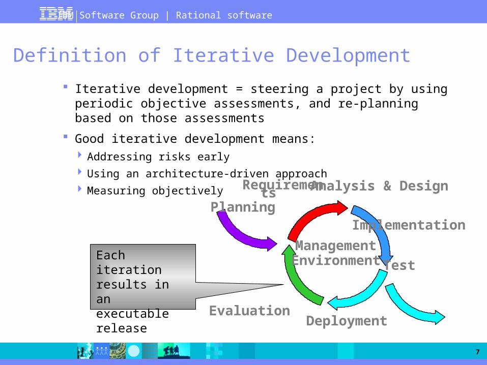
Definition of Iterative Development
Iterative development = steering a project by using periodic objective assessments, and re-planning based on those assessments
Good iterative development means: Addressing risks early
Using an architecture-driven approach
Measuring objectively
Planning
Requirements Analysis & Design
Implementation
Deployment
Test
Evaluation
ManagementEnvironmentEach iteration
results in an executable release

IBM Software Group | Rational software
8
Contrasting Traditional and Iterative Processes
Waterfall Process Iterative Process
Requirements-driven and mostly custom development Late risk resolution Diseconomy of scale
Architecture-driven and component-based Early risk resolution Economy of scale
Requirements Analysis Design Code and
Unit TestSubsystem Integration
SystemTest

IBM Software Group | Rational software
9
Iterations and Phases
Inception: To achieve concurrence among all stakeholders on the lifecycle objectives for the project
Elaboration: To baseline architecture providing a stable basis for the design and implementation efforts in Construction
Construction: To complete the development of the product
Transition: To ensure the product is available for its end users
TransitionConstructionElaborationInception
Transition Iteration
Transition Iteration
Development Iteration
Development Iteration
Development Iteration
Architecture Iteration
Architecture Iteration
Preliminary Iteration

IBM Software Group | Rational software
10
Managing Requirements
Ensures that you: Solve the right problem
Build the right system
By taking a systematic approach to Eliciting
Organizing
Documenting
Managing
The changing requirements of a software application

IBM Software Group | Rational software
11
Use Component-Based Architectures
Basis for reuse Component reuse
Architecture reuse
Basis for project management Planning
Staffing
Delivery
Intellectual control Manage complexity
Maintain integrity
System-software
Middleware
Business-specific
Application-specific
Component-based architecture with layers

IBM Software Group | Rational software
12
Model Visually (UML)
Captures structure and behavior
Shows how system elements fit together
Keeps design and implementation consistent
Hides or exposes details as appropriate
Promotes unambiguous communication The UML provides one language for all
practitioners

IBM Software Group | Rational software
13
Continuously Verify Quality
CostCost
Time
Software problems are100 to 1000 times more costly
to find and repair after deployment
Cost to Repair Software
Cost of Lost Opportunities
Cost of Lost Customers
IBM Software Group | Rational software
14
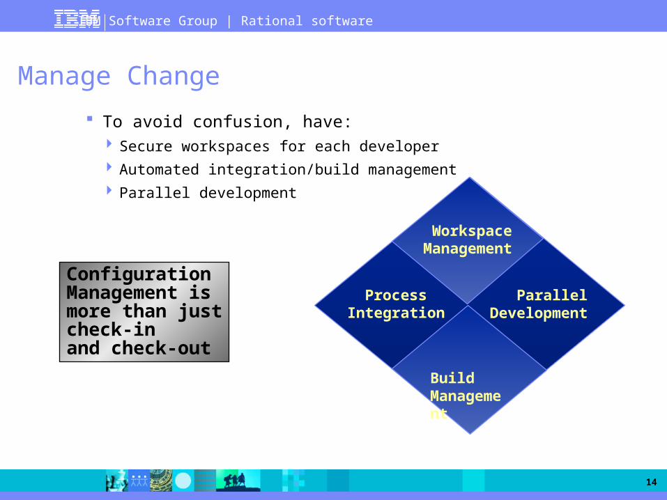
Manage Change
To avoid confusion, have: Secure workspaces for each developer
Automated integration/build management
Parallel development
WorkspaceManagement
Process Integration
Parallel Development
Build Management
Configuration Management is more than just check-in and check-out

IBM Software Group | Rational software
15
Rational Unified Process Implements Best Practices
Iterative approach
Guidance for activities and artifacts
Process focus on architecture
Use cases that drive design and implementation
Models that abstract the system

IBM Software Group | Rational software
16
Bringing It All Together
Disciplines group activities logically
In an iteration, you walk through all disciplines

®
IBM Software Group
© 2006 IBM Corporation
Rational Software France
Object-Oriented Analysis and Design with UML2 and Rational Software Modeler
06. Requirements Overview

IBM Software Group | Rational software
18
Where Are We?
Introduction to Use-Case Modeling
Find Actors and Use Cases
Other Requirements Management Artifacts
IBM Software Group | Rational software
19
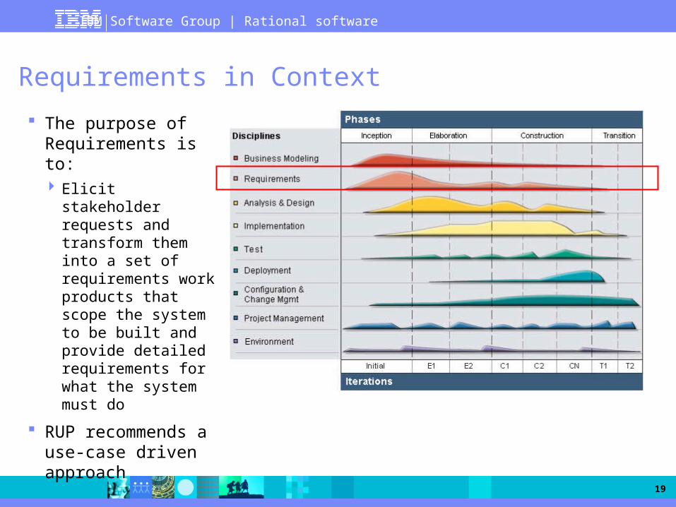
Requirements in Context
The purpose of Requirements is to: Elicit stakeholder
requests and transform them into a set of requirements work products that scope the system to be built and provide detailed requirements for what the system must do
RUP recommends a use-case driven approach

IBM Software Group | Rational software
20
What Is Use-Case Modeling?
Links stakeholder needs to software requirements
Defines clear boundaries of a system
Captures and communicates the desired behavior of the system
Identifies who or what interacts with the system
Validates/verifies requirements
Is a planning instrument
Use Case 2 Specification
Actor 2
Use case 1
Model
Use case 2
Use case 3
IBM Software Group | Rational software
21
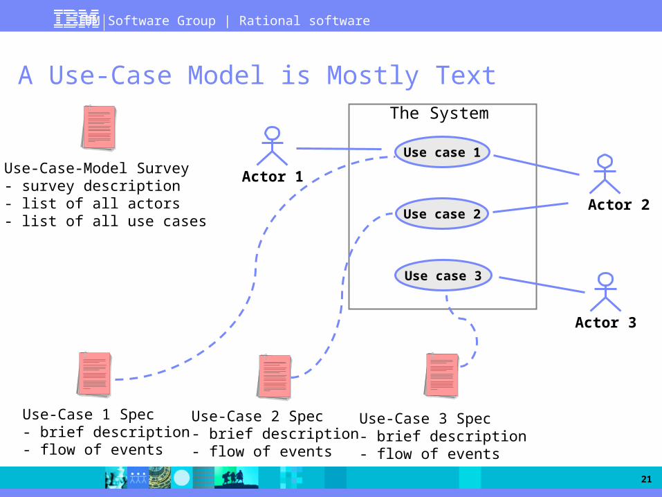
A Use-Case Model is Mostly Text
Use case 1
Use case 2
Use case 3
Use-Case-Model Survey- survey description - list of all actors- list of all use cases
Use-Case 2 Spec- brief description- flow of events
Use-Case 3 Spec- brief description- flow of events
Actor 1
Actor 2
Actor 3
Use-Case 1 Spec- brief description - flow of events
The System

IBM Software Group | Rational software
22
Major Concepts in Use-Case Modeling
An actor represents anything that interacts with the system
A use case is a sequence of actions a system performs that yields an observable result of value to a particular actor
Actor
Use Case

IBM Software Group | Rational software
23
Use-Case Diagram
Bank Consortium
BankCustomer
An Automated Teller Machine (ATM)
Cashier
Withdraw Cash
Transfer Funds
Deposit Funds
Maintain ATMMaintenanceCrew
Collect Deposits

IBM Software Group | Rational software
24
Use Cases Contain Software Requirements
Each use case: Describes actions the system takes to deliver something of value to an actor
Shows the system functionality an actor uses
Models a dialog between the system and actors
Is a complete and meaningful flow of events from the perspective of a particular actor

IBM Software Group | Rational software
25
Benefits of Use Cases
Give context for requirements Put system requirements in logical sequences
Illustrate why the system is needed
Help verify that all requirements are captured
Are easy to understand Use terminology that customers and users understand
Tell concrete stories of system use
Verify stakeholder understanding
Facilitate agreement with customers
Facilitate reuse: test, documentation, and design

IBM Software Group | Rational software
26
Where Are We?
Introduction to Use-Case Modeling
Find Actors and Use Cases
Other Requirements Management Artifacts

IBM Software Group | Rational software
27
Define Actors: Focus on the Roles
An actor represents a role that a human, hardware device, or another system can play in relation to the system
Actor names should clearly denote the actor’s role
?

IBM Software Group | Rational software
28
Case Study: Course Registration System
Review the problem statement provided in the Course Registration Requirements Document
Actor YStudent
Course Registration System
Actor X
Actor Y
Register for Courses
Another Use Case
Use Case 3

IBM Software Group | Rational software
29
How Should I Name a Use Case?
Indicate the value or goal of the actor
Use the active form; begin with a verb
Imagine a to-do list
Examples of variations
Register for Courses
Registering for Courses
Acknowledge Registration
Course Registration
Use Registration System
Which variations show the value to the actor? Which do not?Which would you choose as the use-case name? Why?
IBM Software Group | Rational software
30
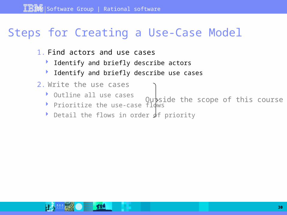
Steps for Creating a Use-Case Model
1. Find actors and use cases Identify and briefly describe actors
Identify and briefly describe use cases
2. Write the use cases Outline all use cases
Prioritize the use-case flows
Detail the flows in order of priority
Outside the scope of this course

IBM Software Group | Rational software
31
Find Actors
Who is pressing the keys (interacting with the system)?
Student Registrar Registration System
The student never touches the system; the registrar operates it. Or, are you building an Internet application?
Online Registration System(www.college.edu)
Student

IBM Software Group | Rational software
32
Identify Actors
Who/what uses the system?
Who/what gets information from this system?
Who/what provides information to the system?
Where in the company is the system used?
Who/what supports and maintains the system?
What other systems use this system?

IBM Software Group | Rational software
33
Find Use Cases
Actor
GOAL 1
GOAL 2
What goal am I trying to achieve by using the system?

IBM Software Group | Rational software
34
Identify Use Cases
What are the goals of each actor? Why does the actor want to use the system?
Will the actor create, store, change, remove, or read data in the system? If so, why?
Will the actor need to inform the system about external events or changes?
Will the actor need to be informed about certain occurrences in the system?
Does the system supply the business with all of the correct behavior?

IBM Software Group | Rational software
35
Group Exercise
Identify the actors who interact with the Course Registration System
Identify use cases for the system
Sketch a use-case diagram

IBM Software Group | Rational software
36
Where Are We?
Introduction to Use-Case Modeling
Find Actors and Use Cases
Other Requirements Management Artifacts

IBM Software Group | Rational software
37
Use-Case Specifications
Name
Brief description
Flow of Events
Relationships
Activity diagrams
Use-Case diagrams
Special requirements
Pre-conditions
Post-conditions
Other diagrams
Use-Case Specifications
...
Use-Case Model
Actors
Use Cases

IBM Software Group | Rational software
38
Use-Case Flow of Events
Has one normal, basic flow
Several alternative flows Regular variants
Odd cases
Exceptional flows for handling error situations

IBM Software Group | Rational software
39
A Scenario Is a Use-Case Instance
Scenario 1
Log on to system.
Approve log on.
Enter subject in search.
Get course list.
Display course list.
Select courses.
Confirm availability.
Display final schedule.
Scenario 2
Log on to system.
Approve log on.
Enter subject in search.
Invalid subject.
Re-enter subject.
Get course list.
Display course list.
Select courses.
Confirm availability.
Display final schedule.
StudentCourse Catalog
System
Register for Courses

IBM Software Group | Rational software
40
Glossary
Glossary
Course Registration System Glossary
1. Introduction
This document is used to define terminology specific to the problem domain, explaining terms, which may be unfamiliar to the reader of the use-case descriptions or other project documents. Often, this document can be used as an informal data dictionary, capturing data definitions so that use-case descriptions and other project documents can focus on what the system must do with the information.
2. Definitions
The glossary contains the working definitions for the key concepts in the Course Registration System.
2.1 Course: A class offered by the university.
2.2 Course Offering: A specific delivery of the course for a specific semester – you could run the same course in parallel sessions in the semester. Includes the days of the week and times it is offered.
2.3 Course Catalog: The unabridged catalog of all courses offered by the university.

IBM Software Group | Rational software
41
Supplementary Specification
Functionality
Usability
Reliability
Performance
Supportability
Design constraints
SupplementarySpecification

IBM Software Group | Rational software
42
Exercise
Perform the exercise provided by the instructor

®
IBM Software Group
© 2006 IBM Corporation
Rational Software France
Object-Oriented Analysis and Design with UML2 and Rational Software Modeler
07. Analysis and Design Overview

IBM Software Group | Rational software
44
Analysis and Design in Context
The purposes of Analysis and Design are to: Transform the
requirements into a design of the system-to-be
Evolve a robust architecture for the system
Adapt the design to match the implementation environment, designing it for performance

IBM Software Group | Rational software
45
Analysis and Design Overview
SupplementarySpecification
Use-Case Model
Analysis Model
Data Model (optional)
ArchitectureDocument
(outside the scope of this course)
Analysis and Design
Glossary
Design Model

IBM Software Group | Rational software
46
The Analysis and Design Workflow
Define System ContextArchitectural AnalysisAssess Viability of Architectural PoCConstruct Architectural PoC
Define System ContextArchitectural AnalysisUse-Case AnalysisOperation Analysis
Identify Design ElementsUse-Case AnalysisOperation AnalysisPrototype the User-InterfaceDesign the User-Interface
Identify Design MechanismsIdentify Design ElementsOperation AnalysisIdentify Services Incorporate Existing Design Elements Structure the Implementation Model Describe the Run-time Architecture Describe Distribution
Use-Case Design Subsystem DesignOperation DesignClass DesignDefine Testability ElementsDesign Testability Elements Capsule Design
Software ArchitectDesigner rolesOther roles

IBM Software Group | Rational software
47
Simplified Workflow for the OOAD Course
Early Elaboration iteration
Goal of Elaboration: To build a robust architecture
that will support the requirements of the system at a reasonable cost and in a reasonable time
To achieve this goal, we need: To produce an evolutionary
executable of production-quality components that will address all architecturally significant risks of the project
Addressing architecturally significant risks means selecting for the iteration the use-case scenarios that expose those risks

IBM Software Group | Rational software
48
A Component-Based Architecture
In RUP, the architecture of a software system is: The organization or structure of the system's significant components
interacting through interfaces,
With components composed of successively smaller components and interfaces
The activities of the Analysis and Design discipline are organized around two major themes: Structure, under the responsibility of the software architect
Architectural layers
Components and interfaces
Contents, under the responsibility of the designers
Analysis and design classes

IBM Software Group | Rational software
49
Roadmap for the OOAD Course
Analysis Architectural Analysis
(Define a Candidate Architecture)
Use-Case Analysis (Analyze Behavior)
Design Identify Design Elements
(Refine the Architecture)
Identify Design Mechanisms (Refine the Architecture)
Class Design (Design Components)
Subsystem Design (Design Components)
Describe the Run-time Architecture and Distribution (Refine the Architecture)
Design the Database
Analysis
Design

IBM Software Group | Rational software
50
Analysis Versus Design
Analysis Design
Focus on understanding the problem
Idealized design
Behavior
System structure
Functional requirements
A small model
Focus on understanding the solution
Operations and attributes
Performance
Close to real code
Object lifecycles
Nonfunctional requirements
A large model

IBM Software Group | Rational software
51
Architectural Views: The 4+1 View Model
Process View Deployment View
Logical View
Use-Case View
Implementation View
End-user
Functionality
Programmers
Software management
Performance, scalability, throughput
System integrators System topology, delivery, installation, communication
System engineering
Analysts/Designers
Structure

IBM Software Group | Rational software
52
Organizing Models in RSA/RSM
Need for well-defined guidelines to represent the architectural views in your modeling and development environment
Whitepaper: “Model Structure Guidelines For Rational Software Modeler And Rational Software Architect (2004 Release)” Available on IBM developerWorks (http://www-128.ibm.com/developerworks/)
Models and packages can contain any number of diagrams One diagram is the “default” diagram, i.e. the diagram that will display when
the owning model or package is opened
The default diagram should contain all the necessary information to navigate in the package, for instance:
Owned packages (double-click opens the package)
Other major owned elements, e.g. public classes and interfaces
Shortcuts to other diagrams (created by drag-and-drop)
Explanatory free text and/or notes
Other guidelines will be introduced as we go along

IBM Software Group | Rational software
53
Determining the (Elaboration) Iteration Scope
The iteration scope is defined in terms of use-case scenarios that best address the drivers for the iteration In the Elaboration phase, the focus is on architecturally significant use-case
scenarios
The implementation of a specific use case will be in most cases spread over several iterations – and in fact phases
There are three main drivers for defining the objectives of an iteration in elaboration:
Risk
Criticality
Coverage

IBM Software Group | Rational software
54

®
IBM Software Group
© 2006 IBM Corporation
Rational Software France
Object-Oriented Analysis and Design with UML2 and Rational Software Modeler
08. Architectural Analysis

IBM Software Group | Rational software
56
Roadmap for the OOAD Course
Analysis Architectural Analysis
(Define a Candidate Architecture)
Use-Case Analysis (Analyze Behavior)
Design Identify Design Elements
(Refine the Architecture)
Identify Design Mechanisms (Refine the Architecture)
Class Design (Design Components)
Subsystem Design (Design Components)
Describe the Run-time Architecture and Distribution (Refine the Architecture)
Design the Database
Analysis
Design

IBM Software Group | Rational software
57
Architectural Analysis
Purpose To define a candidate architecture for the system based on experience
gained from similar systems or in similar problem domains
To define the architectural patterns, key mechanisms, and modeling conventions for the system
Role Software Architect
Major Steps Define the High-Level Organization of Subsystems
Identify Key Abstractions
Develop Deployment Overview
Identify Analysis Mechanisms

IBM Software Group | Rational software
58
Where Are We?
Define the High-Level Organization of Subsystems
Identify Key Abstractions
Develop Deployment Overview
Identify Analysis Mechanisms

IBM Software Group | Rational software
59
Define the High-Level Organization of Subsystems
Purpose To create an initial structure for the Design Model
Normally the design model is organized in layers – a common architectural pattern for moderate to large-sized systems
During architectural analysis, you usually focus on the two high-level layers, that is, the application and business-specific layers This is what is mean by the high-level organization of subsystems

IBM Software Group | Rational software
60
Patterns and Frameworks
Pattern Provides a common solution to a common problem in a context
Analysis/Design pattern Provides a solution to a narrowly-scoped technical problem
Provides a fragment of a solution, or a piece of the puzzle
Framework Defines the general approach to solving the problem
Provides a skeletal solution, whose
details may be Analysis/Design patterns

IBM Software Group | Rational software
61
What Is an Architectural Pattern?
An architectural pattern expresses a fundamental structural organization schema for software systems It provides a set of predefined subsystems, specifies their responsibilities,
and includes rules and guidelines for organizing the relationships between them – Buschman et al, “Pattern-Oriented Software Architecture — A System of Patterns”
Examples:
Layers
Model-view-controller (MVC)
Pipes and filters
Blackboard

IBM Software Group | Rational software
62
The Model-View-Controller (MVC) Architecture
Conceived in the mid-1980's
Extensively applied in most object-oriented user interfaces
Adapted to respond to specific platform requirements, such as J2EE
Model
Manages the application domain’s concepts, both behavior andstate
Controller
Captures user events and determines which actions to take
View
Retrieves the data from the modelor receives it from the controller, and displays it to the user in a way the user
User Event
Change Notification
State Query
View Selection
State Change

IBM Software Group | Rational software
63
An MVC Example: Struts Components
(From the IBM Redbook, Rational Application Developer V6 Programming Guide, June 2005)
IBM Software Group | Rational software
64
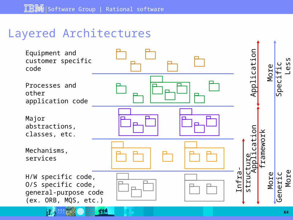
Layered Architectures
Equipment and customer specific code
Processes and other application code
Major abstractions, classes, etc.
Mechanisms, services
H/W specific code, O/S specific code, general-purpose code (ex. ORB, MQS, etc.)
App
licat
ion
fram
ewor
kA
pplic
atio
n
Infr
a-st
ruct
ure
Mor
e G
ener
ic
Mor
e R
euse
Mor
e S
peci
fic
Le
ss R
euse

IBM Software Group | Rational software
65
Layering Considerations
Level of abstraction Group elements at the same level of abstraction
Separation of concerns Group like things together
Separate disparate things
Application vs. domain model elements
Resiliency Loose coupling
Concentrate on encapsulating change
User interface, business rules, and retained data tend to have a high potential for change

IBM Software Group | Rational software
66
Modeling Architectural Layers
Architectural layers can be modeled using packages stereotyped <<layer>>
Software Layers for a Generic J2EE Application
Note: <<global>> is a mere convention used here to indicate layers that can be used by all others

IBM Software Group | Rational software
67
Where Are We?
Define the High-Level Organization of Subsystems
Identify Key Abstractions
Develop Deployment Overview
Identify Analysis Mechanisms
IBM Software Group | Rational software
68
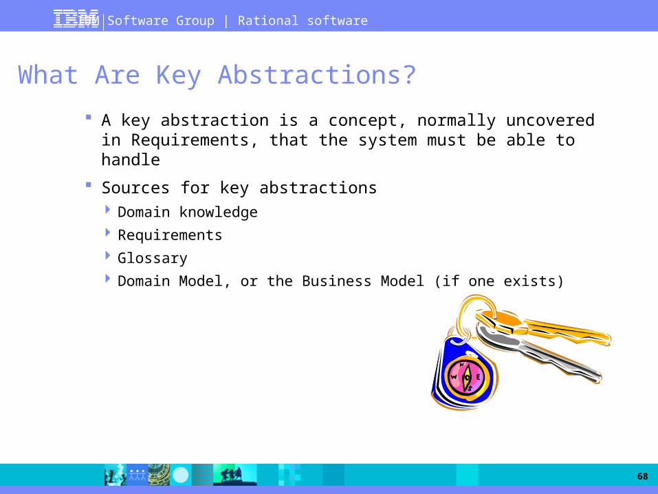
What Are Key Abstractions?
A key abstraction is a concept, normally uncovered in Requirements, that the system must be able to handle
Sources for key abstractions Domain knowledge
Requirements
Glossary
Domain Model, or the Business Model (if one exists)

IBM Software Group | Rational software
69
Describing Key Abstractions
Key abstractions are modeled as analysis classes
For each class, provide A short description of the class
Its main attributes
Its relationships with other classes
Don't spend too much time describing classes in detail at this initial stage The purpose is not to identify classes that
will survive throughout design
You will probably identify classes and relationships not actually needed by the use cases
This initial set of classes is useful to “jump-start” the Use-Case Analysis task
Do not turn the next page before being told to do so!

IBM Software Group | Rational software
70
Group Exercise
Identify the key abstractions for the Course Registration System

IBM Software Group | Rational software
71
Key Abstractions for the Course Registration System

IBM Software Group | Rational software
72
Where Are We?
Define the High-Level Organization of Subsystems
Identify Key Abstractions
Develop Deployment Overview
Identify Analysis Mechanisms
IBM Software Group | Rational software
73
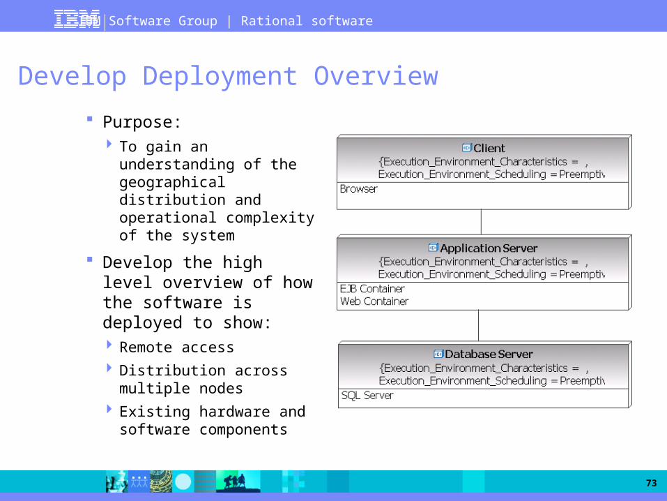
Develop Deployment Overview
Purpose: To gain an understanding of
the geographical distribution and operational complexity of the system
Develop the high level overview of how the software is deployed to show: Remote access
Distribution across multiple nodes
Existing hardware and software components

IBM Software Group | Rational software
74
Where Are We?
Define the High-Level Organization of Subsystems
Identify Key Abstractions
Develop Deployment Overview
Identify Analysis Mechanisms

IBM Software Group | Rational software
75
What Are Analysis Mechanisms?
Analysis mechanisms are architectural mechanisms* used early in the Analysis and Design process: Capture the key aspects of a solution in a way that is implementation
independent
Are “computer science” concepts, usually unrelated to the problem domain
Provide specific behaviors to a domain-related class or component
Examples: Persistence
Inter-process communication
Error or fault handling
Notification
Messaging
Etc.
* Architectural mechanisms = Common concrete solutions to frequently encountered problems

IBM Software Group | Rational software
76
Why Use Analysis Mechanisms?
Analysis mechanisms are used during analysis to reduce the complexity of analysis and to improve its consistency by providing designers with a shorthand representation for complex behavior
Oh no! I found a group of classes that has persistent data. How am I supposed to design these things if I don’t even know what database we are going to be using?
That is why we have a persistence analysis mechanism. We don’t know enough yet, so we can bookmark it and come back to it later.

IBM Software Group | Rational software
77
Identifying and Describing Analysis Mechanisms
Analysis mechanisms can be identified top-down (a priori knowledge) or bottom-up (discovered as you go along) Initially the name might be all that exists (for instance, persistence)
As client classes get identify, it becomes necessary to qualify the use of each mechanism For persistence, identify characteristics like granularity (size), volume
(number), retrieval mechanism, update frequency, etc.
Eventually, analysis mechanisms will be refined into design mechanisms A design mechanism assumes some details of the implementation
environment, but it is not tied to a specific implementation
Example: DBMS as the design mechanism for persistence
And design mechanisms into actual implementation mechanisms Example: Oracle

IBM Software Group | Rational software
78
Exercise
Perform the exercise provided by the instructor
®
IBM Software Group
© 2006 IBM Corporation
Rational Software France
Object-Oriented Analysis and Design with UML2 and Rational Software Modeler
09. Use-Case Analysis

IBM Software Group | Rational software
80
Roadmap for the OOAD Course
Analysis Architectural Analysis
(Define a Candidate Architecture)
Use-Case Analysis (Analyze Behavior)
Design Identify Design Elements
(Refine the Architecture)
Identify Design Mechanisms (Refine the Architecture)
Class Design (Design Components)
Subsystem Design (Design Components)
Describe the Run-time Architecture and Distribution (Refine the Architecture)
Design the Database
Analysis
Design

IBM Software Group | Rational software
81
Use-Case Analysis
Purpose To identify the analysis classes of our system, including:
their “responsibilities”, attributes and associations to other classes, and
usage of analysis mechanisms
Role Designer
Major Steps Create Analysis Use-Case Realization
Supplement the Use-Case Description
Model Use-Case Scenarios with Interaction Diagrams
Model Participating Classes in Class Diagrams
Reconcile the Analysis Use-Case Realizations
Qualify Analysis Mechanisms

IBM Software Group | Rational software
82
Analysis Classes: A First Step Toward Executables
Use CasesAnalysisClasses
SourceCode
ExecDesignElements
Use-Case Analysis

IBM Software Group | Rational software
83
Where Are We?
Create Analysis Use-Case Realization
Supplement the Use-Case Description
Model Use-Case Scenarios with Interaction Diagrams
Model Participating Classes in Class Diagrams
Reconcile the Analysis Use-Case Realizations
Qualify Analysis Mechanisms

IBM Software Group | Rational software
84
What Is a Use-Case Realization?
The bridge between Requirements-centric tasks and Analysis/Design-centric tasks
It provides: A way to trace behavior in the Analysis and Design Models back to the Use-
Case Model
A construct in the Analysis and Design Models, which organizes work products related to the use case but which belong to the design model
Typically consist of sequence and class diagrams
Shown as a collaboration* stereotyped <<use-case realization>>
* UML Collaboration = structure of collaborating elements (roles), each performing a specialized function, which collectively accomplish some desired functionality

IBM Software Group | Rational software
85
What Is a Use-Case Realization?
Class Diagrams
Communication Diagrams
Use-Case Model Analysis/Design Model
Use CaseUse-Case Realization
Sequence Diagrams
Realization Relationship

IBM Software Group | Rational software
86
Where Are We?
Create Analysis Use-Case Realization
Supplement the Use-Case Description
Model Use-Case Scenarios with Interaction Diagrams
Model Participating Classes in Class Diagrams
Reconcile the Analysis Use-Case Realizations
Qualify Analysis Mechanisms

IBM Software Group | Rational software
87
Supplement the Use-Case Description
Purpose: To capture additional information needed in order to understand the required internal behavior of the system that might be missing from the use-case description written for the customer of the system
“The ATM validates the Bank Customer's card.”
“The ATM sends the customer's account number and the PIN to the ATM Network to be validated. The ATM Network returns success if the customer number and the PIN match and the customer is authorized to perform transactions, otherwise the ATM Network returns failure.”
Automated Teller Machine (ATM)

IBM Software Group | Rational software
88
Where Are We?
Create Analysis Use-Case Realization
Supplement the Use-Case Description
Model Use-Case Scenarios with Interaction Diagrams
Model Participating Classes in Class Diagrams
Reconcile the Analysis Use-Case Realizations
Qualify Analysis Mechanisms

IBM Software Group | Rational software
89
Find Classes from Use-Case Behavior
The complete behavior of a use case has to be distributed to analysis classes

IBM Software Group | Rational software
90
What Is an Analysis Class?
System boundary
Use-case behavior coordination
System information
<<boundary>>
<<control>>
<<entity>>
System information
<<entity>>
System boundary
<<boundary>>

IBM Software Group | Rational software
91
What Is a Boundary Class?
Intermediates between the interface and something outside the system
Several Types User interface classes
System interface classes
Device interface classes
Environment dependent GUI
Communication protocols

IBM Software Group | Rational software
92
The Role of a Boundary Class
Model interaction between the system and its environment

IBM Software Group | Rational software
93
Finding Boundary Classes
One boundary class per actor/use case pair
Student Course CatalogRegister for Courses
RegisterForCoursesForm CourseCatalogSystem

IBM Software Group | Rational software
94
Guidelines: Boundary Class
User Interface Classes Concentrate on what information is presented to the user
Do NOT concentrate on the UI details
System and Device Interface Classes Concentrate on what protocols must be defined
Do NOT concentrate on how the protocols will be implemented
Concentrate on the responsibilities, not the details!

IBM Software Group | Rational software
95
What Is an Entity Class?
Represents the key concepts of the system
Models information that must be stored Usually persistent
Environment independent
Not specific to one use case

IBM Software Group | Rational software
96
The Role of an Entity Class
Store and manage information in the system

IBM Software Group | Rational software
97
Finding Entity Classes
Key abstractions usually become entity classes
Entity classes can also be found in: Use-case flow of events (developed during requirements) Glossary (developed during requirements) Business-Domain Model (if business modeling has been performed)
Look for system information that must be stored: Nouns or nominal sentences that identify persistent data are candidates to
become:
Attributes of an entity class, or
Entity classes on their own

IBM Software Group | Rational software
98
Example: Course Registration System
Basic flow of events for the Submit Grades use case:
This use case starts when a Professor wishes to submit student grades for one or more classes completed in the previous semester:
1. The system displays a list of course offerings the Professor taught in the previous semester.
2. The Professor selects a course offering.3. The system retrieves a list of all students who were registered for
the course offering. The system displays each student and any grade that was previously assigned for the offering.
4. For each student on the list, the Professor enters a grade: A, B, C, D, F, or I. The system records the student’s grade for the course offering. If the Professor wishes to skip a particular student, the grade information can be left blank and filled in at a later time. The Professor may also change the grade for a student by entering a new grade.

IBM Software Group | Rational software
99
Example: Course Registration System
Key abstractions (previously identified)
Newly identified classes
How would you characterize the new class?
CourseOffering CourseCatalog Course
ScheduleStudent
Professor
CourseResult

IBM Software Group | Rational software
100
What Is a Control Class?
Use-case behavior coordinator Complex use cases may need more than one control class
Delegates responsibility to other classes
Use-case dependent but environment independent

IBM Software Group | Rational software
101
The Role of a Control Class
Coordinate the use-case behavior

IBM Software Group | Rational software
102
Finding Control Classes
In general, identify one control class per use case As analysis continues, a complex use case’s control class may evolve into
more than one class
Student Course Catalog System
Register for Courses
RegistrationController

IBM Software Group | Rational software
103
Summary: Course Registration System Example
Student Course Catalog System
Register for Courses
Use-Case Model
Design Model
RegisterForCoursesForm CourseCatalogSystem Student Schedule
CourseOffering RegistrationController

IBM Software Group | Rational software
104
Distribute Use-Case Behavior
For each use-case flow of events: Create one or more interaction diagrams (sequence diagrams recommended)
Identify analysis objects responsible for the required use-case behavior
Allocate use-case responsibilities to analysis classes
Use CaseClass Diagrams
Communication DiagramsSequence
Diagrams
Use-Case Realization

IBM Software Group | Rational software
105
Guidelines: Interaction Diagrams and Use Cases
Each initial interaction diagram describes one use-case scenario Diagrams should be named after the use-case scenarios
The interaction should begin with an actor, since an actor always invokes the use case
One diagram is not enough At least one diagram for the main flow of events
Plus at least one diagram for each non-trivial alternative or exceptional flow
Separate diagrams for complex flows

IBM Software Group | Rational software
106
Guidelines: Creating Objects and Classes
Before you start analyzing the use case, put in place: The Actor object that initiates the use case (as previously indicated)
The corresponding boundary and control objects
Other objects that may exist before the use case starts
Example: if there is a pre-condition for a student to be logged in, it is likely the system has already retrieved the corresponding Student object
Assign each object to an existing class or to a new class When creating new classes, capture their semantics immediately
Analysis stereotype
Description, attributes, relationships
Note: Ultimately, classes will be organized into packages and layers but this is NOT the focus of Use-Case Analysis

IBM Software Group | Rational software
107
Guidelines: Allocating Responsibilities
Use-Case behavior is materialized by objects exchanging messages When creating a message, create the corresponding class operation
Convention: start the operation name with “//”
– It identifies the class operation as an analysis responsibility
– Example: // retrieve course offerings for the current semester
– During design, responsibilities will be refined into “real” operations
Who has the data needed to perform the responsibility?
If one class has the data, assign the responsibility to that class
If multiple classes have the data, you can
– Put the responsibility with one class and add a relationship to the other
– Put the responsibility on a “third party” (new class or existing control class for instance) and add relationships to classes needed to perform the responsibility
IBM Software Group | Rational software
108
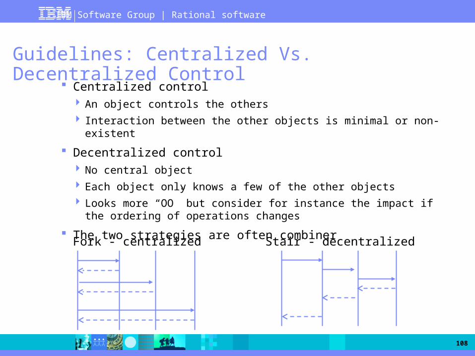
Guidelines: Centralized Vs. Decentralized Control
Centralized control An object controls the others
Interaction between the other objects is minimal or non-existent
Decentralized control No central object
Each object only knows a few of the other objects
Looks more “OO” but consider for instance the impact if the ordering of operations changes
The two strategies are often combiner
Stair - decentralizedFork - centralized

IBM Software Group | Rational software
109
Example: Course Registration System

IBM Software Group | Rational software
110
Exercise 1: Create A Sequence Diagram
Perform the exercise provided by the instructor

IBM Software Group | Rational software
111
Where Are We?
Create Analysis Use-Case Realization
Supplement the Use-Case Description
Model Use-Case Scenarios with Interaction Diagrams
Model Participating Classes in Class Diagrams
Reconcile the Analysis Use-Case Realizations
Qualify Analysis Mechanisms

IBM Software Group | Rational software
112
Reminder: Finding Responsibilities
// PerformResponsibility
:Client :Supplier
Supplier
// PerformResponsibility
Interaction Diagram
Class Diagram
IBM Software Group | Rational software
113
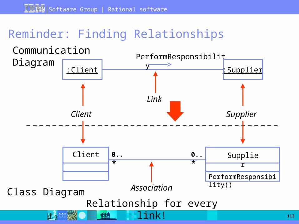
Reminder: Finding Relationships
PerformResponsibility
Link
Association
Communication Diagram
Class Diagram
0..*0..*
Client Supplier
:Client :Supplier
Client Supplier
PerformResponsibility()
Relationship for every link!
IBM Software Group | Rational software
114
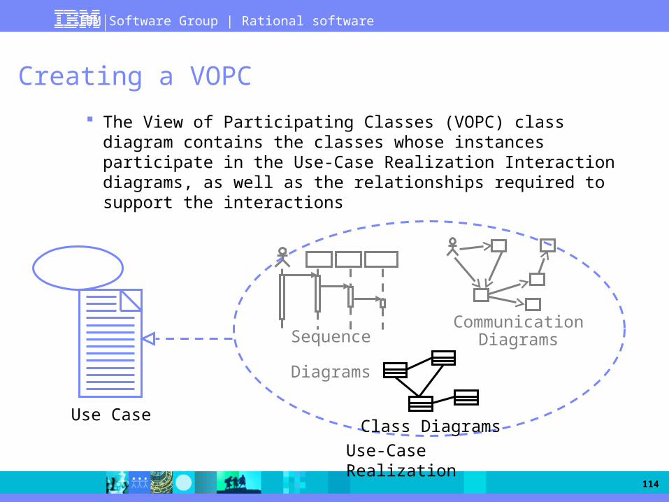
Creating a VOPC
The View of Participating Classes (VOPC) class diagram contains the classes whose instances participate in the Use-Case Realization Interaction diagrams, as well as the relationships required to support the interactions
Use CaseClass Diagrams
Communication DiagramsSequence
Diagrams
Use-Case Realization

IBM Software Group | Rational software
115
Example: Course Registration System
This relationship could have a multiplicity of 1 or it could be replaced by a dependency
This class is a singleton
This relationship could be replaced by a dependency
Three of the relationships are uni-directional. Can you tell why?

IBM Software Group | Rational software
116
Where Are We?
Create Analysis Use-Case Realization
Supplement the Use-Case Description
Model Use-Case Scenarios with Interaction Diagrams
Model Participating Classes in Class Diagrams
Reconcile the Analysis Use-Case Realizations
Qualify Analysis Mechanisms

IBM Software Group | Rational software
117
Reconcile the Analysis Use-Case Realizations
Register for Courses
(White team)
Close Registration(Red team)
Student
CourseOffering
CourseOffering
StudentCloseRegistrationController
RegistrationController
CloseRegistrationForm
CourseCatalogSystem
Schedule
CourseCatalogSystem
CourseOffering
Schedule
RegistrationController
Student
CloseRegistrationController
Schedule
CourseCatalogSystem
BillingSystem
RegisterForCoursesForm
RegisterForCoursesForm
CloseRegistrationForm

IBM Software Group | Rational software
118
Where Are We?
Create Analysis Use-Case Realization
Supplement the Use-Case Description
Model Use-Case Scenarios with Interaction Diagrams
Model Participating Classes in Class Diagrams
Reconcile the Analysis Use-Case Realizations
Qualify Analysis Mechanisms

IBM Software Group | Rational software
119
Describing Analysis Mechanisms
Collect all analysis mechanisms in a list
Draw a map of the client classes to the analysis mechanisms
Identify characteristics of the analysis mechanisms
IBM Software Group | Rational software
120
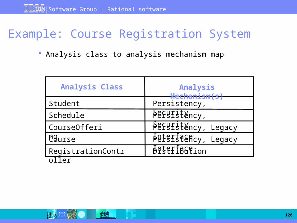
Example: Course Registration System
Analysis class to analysis mechanism map
Analysis Class Analysis Mechanism(s)
Student
Schedule
CourseOffering
Course
RegistrationController
Persistency, Security
Persistency, Legacy Interface
Persistency, Legacy Interface
Distribution
Persistency, Security

IBM Software Group | Rational software
121
Exercise 2: Create A VOPC Diagram
Perform the exercise provided by the instructor
IBM Software Group | Rational software
122