“ I am a United States Sailor. I will support and defend the Constitution
104
-
Upload
clinton-pierce -
Category
Documents
-
view
27 -
download
2
description
SAILOR’S CREED. “ I am a United States Sailor. I will support and defend the Constitution of the United States of America and I W ill obey the orders of those appointed over me. - PowerPoint PPT Presentation
Transcript of “ I am a United States Sailor. I will support and defend the Constitution


“ I am a United States Sailor.
I will support and defend the Constitution
of the United States of America and I W ill obey the orders of those appointed over
me.
I represent the fighting spirit of the Navy and those who have gone before me to defend freedom and democracy around
the world.
I proudly serve my country’s Navy combat team with Honor, Courage, and
Commitment
I am committed to excellence and fair treatment of all. “
SAILOR’S CREED

Lesson 4.14
EXAM REVIWCL
M
G
B
K
BM
KM
DISPLACEMENT
TONS
WEIGHT
TO N S
WEIGHT
B
G

CLASS TOPICS1. Definitions
2. Stability Reference Points
3. Stability Triangle
4. Conditions of Stability
5. Stability Curve
6. Ship’s Hull Markings7. Draft Diagram and Cross Curves

STABILITY - THE TENDENCY OF A SHIP TO ROTATE ONE WAY OR THE OTHER (TO RIGHT ITSELF OR OVERTURN)
INITIAL STABILITY - THE STABILITY OF A SHIP IN THE RANGE FROM 0° TO 7°/10°
OVERALL STABILITY - A GENERAL MEASURE OF A SHIP'S ABILITY TO RESIST CAPSIZING IN A GIVEN CONDITION OF LOADING
DYNAMIC STABILITY - THE WORK DONE IN HEELING A SHIP TO A GIVEN ANGLE OF HEEL

LAWS OF BUOYANCY• A FLOATING OBJECT HAS THE PROPERTY OF BUOYANCY
• A FLOATING BODY DISPLACES A VOLUME OF WATER EQUAL IN WEIGHT TO THEWEIGHT OF THE BODY.
• A BODY IMMERSED (OR FLOATING) IN WATER WILL BE BUOYED UP BY A FORCE EQUAL TO THE WEIGHT OF THE WATER DISPLACED.

DISPLACEMENT
• THE WEIGHT OF THE VOLUME OF WATERTHAT THE SHIP'S HULL IS DISPLACING
• UNITS OF WEIGHT LONG TON = 2240 LBS SHORT TON = 2000 LBS METRIC TON = 2204.72 LBS

VOLUME - NUMBER OF CUBIC UNITS IN AN OBJECT
UNITS: CUBIC FEET CUBIC INCHES
V = L x B x D
20 FT30 FT
6 FT
V = 30 FT x 20 FT x 6 FTV = 3600 FT3

SW = 35 FT3/TONFW = 36 FT3/TONDFM = 43 FT3/TON
SPECIFIC VOLUME - VOLUME PER UNIT WEIGHT
UNITS: CUBIC FEET PER TON
20 FT30 FT
6 FT
V = 3600 FT3
WT = VOLUME SP. VOL
WT = 3600 FT3
35 FT3/TON
WT = 102.86 TONS

CLASS TOPICS1. Definitions
2. Stability Reference Points
3. Stability Triangle
4. Conditions of Stability
5. Stability Curve
6. Ship’s Hull Markings7. Draft Diagram and Cross Curves8. Model

STABILITY REFERENCE POINTS
CL
M
G
B
K
etacenter
ravity
uoyancy
eel
CENTER OF GRAVITY
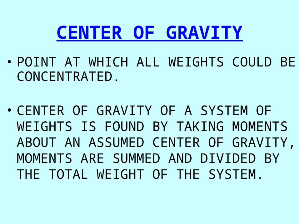
• POINT AT WHICH ALL WEIGHTS COULD BE CONCENTRATED.
• CENTER OF GRAVITY OF A SYSTEM OF WEIGHTS IS FOUND BY TAKING MOMENTS ABOUT AN ASSUMED CENTER OF GRAVITY, MOMENTS ARE SUMMED AND DIVIDED BY THE TOTAL WEIGHT OF THE SYSTEM.

MOVEMENTS IN THE CENTER OF GRAVITY
• G MOVES TOWARDS A WEIGHT ADDITION

MOVEMENTS IN THE CENTER OF GRAVITY
• G MOVES TOWARDS A WEIGHT ADDITION
• G MOVES AWAY FROM A WEIGHT REMOVAL

MOVEMENTS IN THE CENTER OF GRAVITY
• G MOVES TOWARDS A WEIGHT ADDITION
• G MOVES AWAY FROM A WEIGHT REMOVAL
• G MOVES IN THE DIRECTION OF A WEIGHT SHIFT

THEMETACENTER
CL
B
B20B45
M
M20
M45
M70
B70
METACENTER
M
BB1 B2

METACENTER
B SHIFTS
M

MOVEMENTS OF THE METACENTER
THE METACENTER WILL CHANGE POSITIONS IN THE VERTICAL PLANE WHEN THE SHIP'S DISPLACEMENT CHANGES
THE METACENTER MOVES IAW THESE TWO RULES:1. WHEN B MOVES UP M MOVES DOWN.2. WHEN B MOVES DOWN M MOVES UP.

M
G
B
M
G
B
G
M
B
M1
B1
G
M
B
M1
B1
G
M
B
M1
B1
G
M
B
M1
B1

CL
M
G
B
K
GM
KG
BM
KM
LINEAR MEASUREMENTS IN STABILITY

CLASS TOPICS1. Definitions
2. Stability Reference Points
3. Stability Triangle
4. Conditions of Stability
5. Stability Curve
6. Ship’s Hull Markings7. Draft Diagram and Cross Curves8. Model

M
G Z
CL
K
B
G
M
THE STABILITY TRIANGLE

M
G Z
Where:opposite = GZ
hypotenuse = GM
Sin = GZ / GM
GZ = GM x Sin Growth of GZ GM
Sin = opp / hyp

CL
K
B
G
M
G1

G
M
Z
G1 Z1
AS GM DECREASES RIGHTING ARM ALSO DECREASES

G
B
M
INITIALSTABILITY
0 - 7°
CL

M
ZG
B B1
CL
OVERALLSTABILITY
RM = GZ x Wf

CLASS TOPICS1. Definitions
2. Stability Reference Points
3. Stability Triangle
4. Conditions of Stability
5. Stability Curve
6. Ship’s Hull Markings7. Draft Diagram and Cross Curves8. Model

G
B1
M
Z
G
B1
M
B
G
B1
M
B
THE THREE CONDITIONS OF STABILITY
POSITIVE
NEUTRAL
NEGATIVE

CL
K
B
G
M
POSITIVE STABILITY

CL
K
B
GM
NEUTRAL STABILITY

CL
K
B
G
M
NEGATIVE STABILITY

CLASS TOPICS1. Definitions
2. Stability Reference Points
3. Stability Triangle
4. Conditions of Stability
5. Stability Curve
6. Ship’s Hull Markings7. Draft Diagram and Cross Curves8. Model

RIG
HT
ING
AR
MS
(F
T)
ANGLE OF HEEL (DEGREES)9060300 10 20 40 50 70 80
WL20°
G
B
Z
WL
40°
G
B
Z
WL
60°
G
B
Z
GZ = 1.4 FT GZ = 2.0 FT GZ = 1 FT
RIGHTING ARM CURVE

RIG
HT
ING
AR
MS
(F
T)
ANGLE OF HEEL (DEGREES)9060300 10 20 40 50 70 80
WL
WL
20°
G
B
Z
WL
40°
G
B
Z
60°
G
B
Z
GZ = 1.4 FT GZ = 2.0 FT GZ = 1 FT
MAXIMUM RIGHTING ARM
ANGLE OF MAXIMUM RIGHTING
ARM
DANGERANGLE
MAXIMUM RANGE OF STABILITY

CLASS TOPICS1. Definitions
2. Stability Reference Points
3. Stability Triangle
4. Conditions of Stability
5. Stability Curve
6. Ship’s Hull Markings7. Draft Diagram and Cross Curves8. Model

Vertical Weight Shifts
G
B
M
G1G1G1G1G1G1G1
KGo
KG1
GG1 = KG1 - KGo
GG1

KG1 = (Wo x KGo) ± (w x kg)Wf
WHERE;w = Weight Shiftedkg = Distance ShiftedWo = Original DisplacementKGo = Original Height of GWf = Final Displacement± = + if shift up/- if shift down

0
0
1
-1
2
3
4
5
10 20 30 40 50 60 70 80 90ANGLE OF INCLINATION - DEGREES
RIG
HT
ING
AR
MS
(F
T)
KGA = 19 FT KG1 = 19.8 FT
GT = GG1 x Sin O Sin 0° = 0Sin 30°= 0.5Sin 90°= 1.0
GT0°= .8FT x 0 = 0 FT
X
GT30°= .8FT x .5 = .4 FT
X.4 FT
GT90°= .8FT x 1 = .8 FT
X.8 FTFINAL CURVE

Horizontal Weight Shifts
B
M
GG G2G2G2G G2G2G G2G2G2G2G2G2G2G2G2G2G2G2
GG2

GG2 = w x dWf
WHERE;w = Weight Added or Removed
d = Distance Added/Removed from Centerline
Wf = Final Displacement

0
0
1
-1
2
3
4
5
10 20 30 40 50 60 70 80 90ANGLE OF INCLINATION - DEGREES
RIG
HT
ING
AR
MS
(F
T)
KGA = 19 FT KG1 = 19.0 FT GG2 = .9 FT
GP = GG2 x Cos O Cos 0° = 1.0Cos 60°= 0.5Cos 90°= 0
GP0°= .9FT x 1 = 0.9 FT
X.9 FT
GP60°= .9FT x .5 = .45 FT
X.45 FT
GP90°= .9FT x 0 = 0 FT
X
FINAL CURVE
Angle of List

GG3 =B3 x L
12 x 35 x Wf
B = BREADTH OF COMPTL = LENGTH OF COMPTWf = SHIP'S DISPLACEMENT
FREE SURFACE EFFECT

FREE SURFACE EFFECT
• Greater with increased length and width of the compartment
• Increases as draft decreases (de-ballasting)
• Independent of the depth of the liquid
• Can be reduced by pocketing

G3G5 =B x L x Y2
35 x Wf
B = BREADTH OF COMPTL = LENGTH OF COMPTY = DIST FM SHIP C/L TO COMPT COG.Wf = SHIP'S DISPLACEMENT
FREE COMMUNICATIONEFFECT

FREE COMMUNICATIONEFFECT
• COMPARTMENT OPEN TO THE SEA
• COMPARTMENT PARTIALLY FLOODED
• COMPARTMENT OFF-CENTERLINEOR ASYMMETRICAL ABOUT THECENTERLINE

MP
LCF
CFD
LCF - The Longitudinal Center of Flotation

DRAG - A design feature having the draft aft greater than the draft fwd. Primarily done to increase plant effectiveness.
16' 0" 14' 0"DWL
DRAG = 2 FT By the Stern

TRIM - The difference between the forward and after drafts in excess of drag.
16' 14'
DRAG = 0
TRIM = 2 FT By the Stern

LCF
MP FPAP
Trimming Moment = w x TA
wTA
Change in Trim(CT) = TM MT1"

LCF
MP FPAP
Trimming Moment = w x TA
Change in Trim(CT) = TM MT1"
LCF
MP FPAP
LCF
MP FPAP
LCF
MP FPAP
LCF
MP FPAP
LCF
MP FPAP
LCF
MP FPAP
LCF
MP FPAP
LCF
MP FPAP
CT

df CT
LBP/2 + LCF LBP=
df CT
LBP/2 + LCF LBP=
df CT
LBP/2 + LCF LBP=
df CT
LBP/2 + LCF LBP=
df CT
LBP/2 + LCF LBP=
df CT
LBP/2 + LCF LBP=
df CT
LBP/2 + LCF LBP=
df CT
LBP/2 + LCF LBP=
df =(LBP/2 + LCF)
LBPx CT
dadf +CT =
da= dfCT -

Parallel Rise (PR) is the distance that the drafts fore and aft decrease due to a weight removal.
PARALLEL RISE = w TPI-
Parallel Sinkage (PS) is the distance that the drafts fore and aft increase due to a weight addition.
PARALLEL SINKAGE = w TPI

ABILITY TO REFLOAT
“IF THE PROPS ARE REVERSED AND THERE ISNO TENDENCY OF THE SHIP TO BACK AWAYFROM THE BEACH, NO FURTHER ATTEMPTS TOMOVE THE SHIP BY MEANS OF THE PROPELLERSSHOULD BE USED.”
NSTM 079 VOL 1 REPAIR PARTY MANUAL NTTP 3-20.31

BRIDGE ACTIONS
• RIG GROUND TACKLE & KEDGE ANCHORS (IFPOSSIBLE)
• COORDINATE LIGHTENING SHIP WITH HIGH TIDE
• TAKE A STRAIN ON GROUND TACKLE
• REQUEST SALVAGE ASSISTANCE
HW
LW

DCA ACTIONS
• WEIGH THE SHIP DOWN HARD

AGROUND: DCA ACTION
WEIGH THE SHIP DOWN HARD
• SOUND ALL TANKS & VOIDS
• CHECK FUEL TANKS FOR LEAKAGE
• STRUCTURAL DAMAGE?
• EXTENSIVE SOUNDINGS (LOWER SMALL BOATS)
ABOUT THE SHIP
SEAWARD
INVESTIGATE FOR DAMAGE

AGROUND: DCA ACTION
DETERMINE AMOUNT OF TONS AGROUND
• FM KNOWN DRAFTS, DETERMINE ORIGINAL DISPLACEMENT
• READ DRAFTS AFTER AGROUND
• DETERMINE NEW DISPLACEMENT
• DIFFERENCE EQUALS TONS AGROUND
• IF STABILITY IS CRITICAL, LOWER G & ESTIMATE TIME
• ELIMINATE HIGH WEIGHT
• FLOOD LOW COMPARTMENTS
CALCULATE CRITICAL DRAFT

M
G
B
K

MG
B
K
Remember: G moves faster than M!!Remember: G moves faster than M!!

MG
B
K

HULL GIRDER STRESS
ACTIONS
INDICATORS
-SHIP IS HOGGING OR SAGGING-STRESS FRACTURES, CRACKS, "CRINKLING", OR PANTING OF BULKHEADS, DECKS AND STIFFENERS
-RELIEVE HOGGING OR SAGGING-SHORE UP BULKHEADS/DECKS. -REINFORCE WHERE POSSIBLE.

Sagging Stresses
C
T
Quiz: What would be the corrective actions??

Hogging Stresses
T
C

Docking
• Transfer of Responsibility• Pumping of Drydock
– Upon Touching Blocks: Hull Inspection
• Dock Pumped Dry• Hull Board Inspection
– Ship Properly Docked and Shores in Place– NOTE Condition of Screws, Rudders, Sea
Suctions & Discharges, Cathodic Protection, ANY DAMAGE

Undocking
• Ensure all Sea Valves Have Been Properly Reinstalled
• Man All Spaces with Sea Valves
• Augment Sounding and Security Watches
• Docking Officer Provide Ship with Undocking Report

"IF PERSONNEL WAIT UNTIL CATASTROPHE IS ACTUALLY IMPENDING BEFORE STARTING TO LEARN THEIR SHIP BY MEANS OF THE FOREGOING PREPARATORY MEASURES, THE SHIP AND ITS COMPANY MAY BE LOST."
NSTM 079 VOL I

"IF PERSONNEL WAIT UNTIL CATASTROPHE IS ACTUALLY IMPENDING BEFORE STARTING TO LEARN THEIR SHIP BY MEANS OF THE FOREGOING PREPARATORY MEASURES, THE SHIP AND ITS COMPANY MAY BE LOST."
NSTM 079 VOL I

"IF PERSONNEL WAIT UNTIL CATASTROPHE IS ACTUALLY IMPENDING BEFORE STARTING TO LEARN THEIR SHIP BY MEANS OF THE FOREGOING PREPARATORY MEASURES, THE SHIP AND ITS COMPANY MAY BE LOST."
NSTM 079 VOL I

G
B
WATER LEVEL
SHIP SINKINGS• BODILY SINKAGE
• CAPSIZING
• PLUNGING
• BREAKING UP
LOSS OF BUOYANCY
LOSS OF TRANSVERSE STABILITY
LOSS OF LONGITUDINAL STABILITY
LOSS OF SHIP'S GIRDER

METACENTRIC HEIGHTRIGHTING ARM (GZ) IS PROPORTIONAL TO METACENTRIC
HEIGHT (GM)
A SHIP WITH:
LARGE GM IS STIFF AND RESISTS ROLLS
SMALL GM IS TENDER AND ROLLS EASILY AND SLOWLY
VERY SMALL GM IS APT TO HANG AT THE END OF EACH ROLL BEFORE STARTING UPRIGHT
SLIGHTLY NEGATIVE GM IS APT TO LOLL (STAYING HEELED AT ANGLE OF INCLINATION WHERE RIGHTING AND UPSETTING FORCES ARE EQUAL) AND FLOP FROM SIDE TO SIDE
NEGATIVE GM WILL CAPSIZE WHEN INCLINED

3 BASIC CONDITIONS WHICH MAY CAUSE THESHIP TO TAKE ON A PERMANENT LIST:
• G MOVED OFF CENTERLINE (99%)
• -GM (1%)
• COMBINATION OF -GM AND G OFF CL
G G2
G2G
M
G
M

CAUSES of -GM
1. Removal of low weights
2. Addition of high weights (ice)
3. Moving weights upward
4. Free Surface Effect
5. Free Communication Effect

FLOODABLE LENGTH
STEM - FRAME 100FRAMES - 32-140FRAMES - 64-180FRAMES - 100-212FRAMES - 140-250FRAMES - 180-292FRAMES - 212-328FRAMES - 250-368FRAMES - 292-STERN
A LIST OF FLOODABLE COMPARTMENT GROUPS IS OFTEN FOUND. FOR EXAMPLE, FOR A FFG-7:
GENERAL RULE: SHIP'S LBP > 300 FT 15% LBP < 300 FT 2 SPACES<100 FT 1 SPACE

FLOODABLE LENGTH DAMAGE
Second Deck (DC Dk)First PlatformMain Deck Second Platf
Second Deck (DC Dk)First PlatformMain Deck Second Platf
212328

ANGLE OF SEMI-PERMANENT
HEEL
A
AREA A = AREA B
B
ANGLE OF MAX ROLL
RESERVE DYNAMIC STABILITY
HEELING EFFECTS OF BEAM WINDS
FULL LOAD
100 KT
RIG
HT
ING
AR
MS
(F
T)
ANGLE OF HEEL (DEG)

HEELING EFFECTS OF BEAM WINDS
FULL LOAD
100 KT DAMAGED
RIG
HT
ING
AR
MS
(F
T)
ANGLE OF HEEL (DEG)

RIG
HT
ING
AR
MS
(F
T)
ANGLE OF HEEL (DEG)
FULL LOAD
100 KT
60 KT
HEELING EFFECTS OF BEAM WINDS

Limitations to Ship’s Design Criteria In order to maintain a satisfactory condition with regard to
stability and reserve buoyancy, the following guidelines must be adhered to:
• Limiting Draft Marks not Submerged Prior to Damage
• No Abnormal Topside Weights
• Liquid Loading Instructions are Followed
• Watertight Integrity is Maintained

IMMEDIATE STEPS
STEP ONE -
STEP TWO -
ESTABLISH FLOODING BOUNDARIES
DEWATER ANY SPACE COLORED PINK ON THE FLOODING EFFECTS DIAGRAM.

STEP THREE -
SIZE UP THE SITUATION TO DETERMINE WHETHER STABILITY IS CRITICAL BEFORE ANY FURTHER ACTION IS TAKEN.
IMMEDIATE STEPS

CRITICAL STABILITY1. The ship has a negative GM
2. The ship is listing to the danger angle (1/2 angle of max GZ)
3. The extent of flooding exceeds floodable length.
4. High winds or rough seas combined with flooding

STEP FOUR -ELIMINATE OR REDUCE LIST
IMMEDIATE STEPS

EXCESSIVE TRIM (> 1% LBP)
ACTIONS
SHIFT CENTER OF GRAVITY TOWARDS "HIGH" END.
Don’t forget about:

5-328-2-W20201
5-344-0-J
40
5-328-0-J
35 436
100P
5-292-0-E5-321-1-F 3-292-2-E
5-292-1-W
84
15
1 0
5-328-1-W
201
20
894
215S
5-250-0-E
85-308-2-W
83
8
5-276-0-F
5-308-1-W83
5-292-2-W
5-292-3-W
9
6
9
84
CAPACITY-TONS SW
COMPARTMENT NUMBER
INCLINING MOMENTS FT-T
(GREEN) - FLOODING OF GREEN SPACES WILL IMPROVE STABILITY, EVEN THOUGH FREE SURFACE EXISTS.
(YELLOW) - FLOODING OF YELLOW SPACES WILL IMPROVE STABILITY IF NO FREE SURFACE EXISTS. IF SPACE IS NOT 100% FULL STABILITY WILL BE IMPAIRED.
(PINK) - FLOODING OF PINK SPACES WILL DECREASE STABILITY BECAUSE OF ADDED HIGH WEIGHT, FREE SURFACE EFFECT OR BOTH.
(WHITE) - FLOODING OF WHITE SPACES HAS NO APPPRECIABLE EFFECT ON STABILITY.

5-328-2-W20+2 -1
1.0
5-328-1-W20
+2-1
1.0
5-344-0-J
30 0
+4 -3
5-328-0-J
27 0
+3 -2
8
8
5-308-2-W
5-308-1-W0.4
0.4
+1
+1 0
0
5-292-2-W
5-292-3-W
9
9
0.5
0.5
+1
+1
0
0
CLEAN BALLAST
POTABLE WATER
JP-5
CAPACITY-TONS LIST
COMPARTMENT NUMBER
CHANGE IN DRAFTAFT - INCHES
CHANGE IN DRAFTFWD - INCHES

WEIGHT AND MOMENT COMPENSATION PROGRAM
• Status I: No displacement or Stability problems
• Status II: Deficient in both margins
• Status III: Deficient in KG margin
• Status IV: Deficient in displacement margin

“Intentionally Left Blank”

LIMITATIONS
• Follow Liquid Loading Instructions
• No Abnormal Topside Weights
• Don’t Submerge Limiting Draft Marks
• Maintain Watertight Integrity

LIMITATIONS
• Follow Liquid Loading Instructions
• No Abnormal Topside Weights
• Don’t Submerge Limiting Draft Marks
• Maintain Watertight Integrity

LIMITATIONS
• Follow Liquid Loading Instructions
• No Abnormal Topside Weights
• Don’t Submerge Limiting Draft Marks
• Maintain Watertight Integrity

DEFINITIONSROLL -The action of a vessel involving
a recurrent motion (Longitudinal Axis).
HEEL -Semi-permanent angle of inclination, caused by external forces.
LIST - Permanent angle of inclination caused by a shift in the center of gravity so as to cause G off CL, a -GM, or a combination of the two.

MH1o = GM x Wf x 0.01746
List =w x dMH1o

INCLINING EXPERIMENT Completed upon commissioning, and
following each major overhaul or shipalt.
It is done to verify the exact location of the ship's center of gravity (KG).
Basis for updates to Section II(a) of the DC book and for changes to weight and moment compensation status
INACCURACIES
1. UNACCOUNTED FOR FSE
2. MOVEMENT OF PERSONNEL
3. INACCURATE WEIGHTS
4. TAUGHT LINES
5. POOR WEIGHT VERIFICATION WALK THROUGH

MOB-D-6-SF Righting Ship
Conducted: Every 18 Months (SEMI annual for CG)
Purpose: To train the damage control organization in correcting a list.
Requirements: Condition 1 and zebra set. Liquid loading may be varied to put an actual list or trim on the ship if desired.

REASONS FOR BALLASTING
• INCREASE WEIGHT LOW TO IMPROVE STABILITY
• ELIMINATE EXCESSIVE LIST / TRIM
• COUNTERFLOOD FOLLOWING DAMAGE TO OFF CENTER COMPARTMENT
• EXPLOSION ABSORPTION (CV & CVN)
• WET WELL OPERATIONS (AMPHIBS)
• GROUNDING “Weigh the ship down hard”
• SUPPRESS FREE SURFACE EFFECT
• BALLASTING is the process of filling low compartments from the sea to improve ship stability or control list / trim.
• BALLASTING systems may be independent (clean ballast) or they may incorporate sections of the fuel and drainage systems (dirty ballast).
DEFINITION
LIQUID BALLAST SYSTEMS
• AUTOMATIC (FUEL OIL COMPENSATION)
• MANUAL SYSTEMS

MANUAL BALLAST SYSTEMS
• INDEPENDENT
• FUEL TANK SYSTEMS

ARGUMENTS AGAINST BALLASTING
• "It Will Destroy My Tanks"- MPA
• "I've Never Seen It Done Before. It Must
Not Be Necessary." - CHENG
• "When We Pump Out The Ballast Tanks, It
Will Pollute The Water." - CO

BALLASTING RESPONSIBILITIES OF DCA
• Maintain Awareness Of Ship's Liquid Loading Condition. (Full Load - Min Ops)
• Determine The RisksRisks Associated With Violating LLI And Report To CHENG If Necessary.– HOGGING AND SAGGING STRESSES.– SUBMERGING LIMITING DRAFT MARKS.– SURVIVABILITY OF BEAM WINDS AND SEAS.– MAINTAIN ADEQUATE METACENTRIC HEIGHT.
• Ensure Most Current Fuel And Water Report Is Posted Daily At Each Repair Locker and DC Central.

50% Theory 50% Problems• Study in groups…
• Check your work…
• Follow your units…
• Check your work…
• Draw a picture…
• Check your work…

Good Luck!Good Luck!
• Check your work…• Follow your units…• Draw a picture…