È /Ãÿ «EW¿»iS +$.8?MÜ& `èÈI2AÅ- …...bibliography), "Intelligent Vehicle Systems" are...
32
ETSI TR 101 982 V1.2.1 (2002-07) Technical Report Electromagnetic compatibility and Radio spectrum Matters (ERM); Radio equipment to be used in the 24 GHz band; System Reference Document for automotive collision warning Short Range Radar
Transcript of È /Ãÿ «EW¿»iS +$.8?MÜ& `èÈI2AÅ- …...bibliography), "Intelligent Vehicle Systems" are...
ETSI TR 101 982 V1.2.1 (2002-07)
Technical Report
Electromagnetic compatibilityand Radio spectrum Matters (ERM);
Radio equipment to be used in the 24 GHz band;System Reference Document for automotive collision
warning Short Range Radar
ETSI
ETSI TR 101 982 V1.2.1 (2002-07) 2
Reference RTR/ERM-RM-013
Keywords radar, radio, short range
ETSI
650 Route des Lucioles F-06921 Sophia Antipolis Cedex - FRANCE
Tel.: +33 4 92 94 42 00 Fax: +33 4 93 65 47 16
Siret N° 348 623 562 00017 - NAF 742 C
Association à but non lucratif enregistrée à la Sous-Préfecture de Grasse (06) N° 7803/88
Important notice
Individual copies of the present document can be downloaded from: http://www.etsi.org
The present document may be made available in more than one electronic version or in print. In any case of existing or perceived difference in contents between such versions, the reference version is the Portable Document Format (PDF).
In case of dispute, the reference shall be the printing on ETSI printers of the PDF version kept on a specific network drive within ETSI Secretariat.
Users of the present document should be aware that the document may be subject to revision or change of status. Information on the current status of this and other ETSI documents is available at
http://portal.etsi.org/tb/status/status.asp
If you find errors in the present document, send your comment to: [email protected]
Copyright Notification
No part may be reproduced except as authorized by written permission. The copyright and the foregoing restriction extend to reproduction in all media.
© European Telecommunications Standards Institute 2002.
All rights reserved.
DECTTM, PLUGTESTSTM and UMTSTM are Trade Marks of ETSI registered for the benefit of its Members. TIPHONTM and the TIPHON logo are Trade Marks currently being registered by ETSI for the benefit of its Members. 3GPPTM is a Trade Mark of ETSI registered for the benefit of its Members and of the 3GPP Organizational Partners.
ETSI
ETSI TR 101 982 V1.2.1 (2002-07) 3
Contents
Intellectual Property Rights ................................................................................................................................4
Foreword.............................................................................................................................................................4
Introduction ........................................................................................................................................................4
1 Scope ........................................................................................................................................................5
2 References ................................................................................................................................................5
3 Definitions, symbols and abbreviations ...................................................................................................5 3.1 Definitions..........................................................................................................................................................5 3.2 Symbols..............................................................................................................................................................8 3.3 Abbreviations .....................................................................................................................................................8
4 Executive summary ..................................................................................................................................9 4.1 Status of the System Reference Document.......................................................................................................10 4.2 Technical Issues ...............................................................................................................................................10
5 Main conclusions....................................................................................................................................13
Annex A: Detailed market information........................................................................................................14
A.1 Applications ...........................................................................................................................................14
A.2 Market size and value.............................................................................................................................14
A.3 Traffic evaluation ...................................................................................................................................15
Annex B: Technical information ...................................................................................................................16
B.1 Detailed technical description ................................................................................................................16
B.2 Technical justifications for spectrum .....................................................................................................22 B.2.1 Power................................................................................................................................................................22 B.2.2 Frequency (See also spectrum requirements clause 4.2) ..................................................................................22 B.2.2.1 Unit Size .....................................................................................................................................................23 B.2.2.2 Unit Cost factors and cost estimation overview..........................................................................................23 B.2.2.2.1 Required Bandwidth/Range Separation ................................................................................................24 B.2.2.2.2 Application Capability ..........................................................................................................................25 B.2.2.2.3 Mass Production Capability ..................................................................................................................25 B.2.2.2.4 Frequency Allocation ............................................................................................................................25 B.2.3 Bandwidth and other radio parameters .............................................................................................................26
B.3 Information on current version of relevant ETSI standard.....................................................................28
Annex C: Expected compatibility issues.......................................................................................................29
C.1 Coexistence studies (if any) ...................................................................................................................29
C.2 Current ITU allocations..........................................................................................................................29
C.3 Sharing issues.........................................................................................................................................29
Annex D: Item check lists (remaining Items)................................................................................................30
Annex E: Bibliography...................................................................................................................................31
History ..............................................................................................................................................................32
ETSI
ETSI TR 101 982 V1.2.1 (2002-07) 4
Intellectual Property Rights IPRs essential or potentially essential to the present document may have been declared to ETSI. The information pertaining to these essential IPRs, if any, is publicly available for ETSI members and non-members, and can be found in ETSI SR 000 314: "Intellectual Property Rights (IPRs); Essential, or potentially Essential, IPRs notified to ETSI in respect of ETSI standards", which is available from the ETSI Secretariat. Latest updates are available on the ETSI Web server (http://webapp.etsi.org/IPR/home.asp).
Pursuant to the ETSI IPR Policy, no investigation, including IPR searches, has been carried out by ETSI. No guarantee can be given as to the existence of other IPRs not referenced in ETSI SR 000 314 (or the updates on the ETSI Web server) which are, or may be, or may become, essential to the present document.
Foreword This Technical Report (TR) has been produced by ETSI Technical Committee Electromagnetic compatibility and Radio spectrum Matters (ERM).
It includes necessary information to support the co-operation under the MoU between ETSI and the European Radiocommunications Committee (ERC) of the European Conference of Post and Telecommunications Administrations (CEPT) for amending CEPT/ERC Recommendation 70-03 [1].
Introduction The industry has responded to European Commission programs and has developed new, efficient 24 GHz Short Range Radar (SRR) solutions for Road Safety and Intelligent Transport Systems. This is in support of such programs as IST, the EU Approach to Road Safety and Intelligent Transport Systems (ITS) and RESPONSE, Project TR4022 (see bibliography).
This Systems Reference Document relates to a basic element of the IST program for the automotive sector and can be applied in a variety of applications.
The objective and focus of "The EU Approach to Road Safety and Intelligent Transport systems (ITS)" (see bibliography), "Intelligent Vehicle Systems" are defined as "Improve Safety, Security, Comfort and Efficiency in all Transport modes" and "Focusing on Advanced Pilot/Driver Assistance Systems (in support of vision, alertness, manoeuvring, automated driving compliance with the regulations, etc.)".
Further the new 24 GHz Radar system is an essential "building block" of the EU Project RESPONSE, Project TR4022 (see bibliography) Advanced Driver Assistance Systems: "System Safety and Driver Performance".
ETSI
ETSI TR 101 982 V1.2.1 (2002-07) 5
1 Scope The present document applies to Short Range Devices (SRD) in the field of SRR operating at very low power levels for exterior automotive applications for vehicle environmental sensing.
These applications require antenna characteristics, which necessitate narrow beam and low elevation antenna angles with a limited mounting height.
The present document describes the technical characteristics of SRRs, the Radio frequency requirements as a wideband frequency range, for the carrier frequency operating in the 24 GHz SRD as specified in CEPT/ERC Recommendation 70-03 [1]. The devices also use the SRD Band for a movement sensor function implementing a Doppler mode for a target speed measurement function.
The EN 301 091 [3] presents a basis for the new cost efficient and versatile 24 GHz radar technology, which complements 77 GHz Automotive Cruise Control (ACC) functions.
The following information is given in:
• Annex A: Detailed market information;
• Annex B: Technical information;
• Annex C: Expected compatibility issues.
2 References For the purposes of this Technical Report (TR) the following references apply:
[1] CEPT/ERC Recommendation 70-03: "Relating to the use of Short Range Devices (SRD)".
[2] ETSI EN 300 440-1: "Electromagnetic compatibility and Radio spectrum Matters (ERM); Short range devices; Radio equipment to be used in the 1 GHz to 40 GHz frequency range; Part 1: Technical characteristics and test methods".
[3] ETSI EN 301 091: "ElectroMagnetic Compatibility and Radio Spectrum Matters (ERM); Road Transport and Traffic Telematics (RTTT); Technical characteristics and test methods for radar equipment operating in the 76 GHz to 77 GHz band".
[4] "Short Range Automotive Radar (SRR)", ERO/ERC workshop 20 March 2001, RegTP Mainz.
NOTE: http://www.ero.dk/eroweb/srd/SRD-UWB.htm
[5] EC SPEECH/02/181, Errki Likkanen, "Towards a comprehensive eSafety Action Plan for improving road safety in Europe", High level meeting on Safety Brussels 25 April 2002.
[6] FCC 02-48: "Revision of Part 15 of the Commission's Rules Regarding Ultra-Wideband Transmission Systems", First Report and Order, April 22nd, 2002.
3 Definitions, symbols and abbreviations
3.1 Definitions For the purposes of the present document, the following terms and definitions apply:
accuracy: degree of conformity of a measured or calculated value to its definition or with respect to a standard reference (see uncertainty)
ambiguity: properties of something that allows it to have more than one possible meaning
ETSI
ETSI TR 101 982 V1.2.1 (2002-07) 6
auto-correlation: measure of the similarity between a signal and a time-shifted replica of itself
bandwidth: range of frequencies, expressed in Hertz (Hz), that can pass over a given transmission channel
NOTE: The bandwidth determines the rate at which information can be transmitted.
Binary Phase Shift Keying (BPSK): DSB suppressed carrier discrete phase modulation
chip: time it takes to transmit a bit or single symbol of a PN code
coherent homodyne detection: synchronous receive process with a local carrier of same frequency and phase
correlator: SS receiver component that demodulates a Spread Spectrum signal; a device that measures the similarity between an incoming signal and a stored replica
cross-correlation: measure of the similarity of two different signals
de-spreading: process used by a correlator to recover narrowband information from a spread spectrum signal
diffraction loss: loss between two antennas caused by the scattering of energy from obstruction in the path
directive gain: in a given direction, 4pi times ratio of the radiation intensity in that direction to the total power radiated by the antenna
Direct Sequence Spread Spectrum (DSSS): It can be assumed that the information signal in DSSS transmission is spread at baseband, and the spread signal is then modulated in a second stage.
drift (frequency): the linear (first-order) component of a systematic change in frequency of an oscillator over time. Drift is due to aging plus changes in the environment and other factors external to the oscillator data symbol.
duty cycle: As defined in SRD REC 70-03, the ratio, expressed as a percentage, of the maximum transmitter "on" time and referenced to a given observation time.
Dwell time: continuous time duration a carrier frequency stays within a given frequency channel
Federal Communications Commission, Notice of Proposal Rule Making (FCC NPRM): The regulative authority of the United States (FCC) has started a rule making process regarding ultrawideband transmitters which will result into a standard amendment of 47FDR part 15. One important document during this process is the "notice of proposed rulemaking", released in 5/2000.
fractional bandwidth: in a design the ratio of necessary bandwidth divided by the carrier frequency e.g. 3 GHz / 24 GHz = 12,5 %
free-space path loss: in an antenna, the loss between two isotropic radiators in free space resulting from the decrease in power density with the square of the separation distance
frequency allocation (of a frequency band): entry in the Table of Frequency Allocations of a given frequency band for the purpose of its use by one or more terrestrial or space radiocommunication services or the radio astronomy service under specified conditions
NOTE: This term is also applied to the frequency band concerned.
frequency assignment: authorization given by a nation's government for a station or an operator in that country to use a specific radio frequency channel under specified conditions
Frequency Shift Keying (FSK): modulation where the data causes the frequency of the carrier to change from one frequency to another on discrete stages
gain, dBd: antenna gain, expressed in decibels referenced to a half wave dipole
gain, dBi: antenna gain, expressed in decibels referenced to a theoretical isotropic radiator
gain, dBic: antenna gain, expressed in decibels referenced to a theoretical isotropic radiator that is circularly polarized
Half Power Beam Width (HPBW): in an antenna, the angular sector in degrees of the radiated power pattern at the half-power (3 dB) point
ETSI
ETSI TR 101 982 V1.2.1 (2002-07) 7
Industrial Scientific and Medical bands (ISM): frequency bands in which non-radio RF emissions can be allocated
NOTE: Generally also allowed for secondary radio services i.e. SRD's.
isotropic radiator: hypothetical, loss less antenna having equal radiation intensity in all directions; used as a zero-dB gain reference in pattern measurements or directivity calculations
K, Ku, Ka Bands: frequency band between 18 GHz to 27 GHz, Ku 12 GHz to 18 GHz, Ka 27 GHz to 40 GHz
microwave: signal in the generic frequency range from above 1 GHz to an upper end of perhaps 30 GHz or 40 GHz
NOTE: This is the frequency range where coaxial cabled TEM mode signal propagation is viable.
narrowband: classification for the spectral width of a transmission system
NOTE: Generally considered if the fractional BW is below 1% of the carrier frequency.
non-coherent detection: envelope receive process without phase coherency to the reference carrier but any subcarrier
occupied bandwidth: bandwidth of an emission defined for UWB or alike systems as 10 dB bandwidth of the power spectral density
NOTE: 10 dB definition also according to FCC NPRM.
peak power density: peak power density in 50 MHz bandwidth.
polarization: in an antenna, the direction in which the electric field vector is aligned during the passage of at least one full cycle
Power Spectral Density (dBm/Hz) (PSD): Some limit specifications prefer a definition of PSD as a power in a certain measurement resolution bandwidth, e.g. -30 dBm in 1 MHz, which is equivalent -90 dBm/Hz.
processing gain: ratio of the bandwidth of a spread spectrum signal to the bandwidth of the baseband signal
Pseudo Noise (PN): digital signal with noise-like properties
NOTE: Also a wideband modulation which imparts noise-like characteristics to an RF signal.
PN Code: digital bit stream with noise-like characteristics
Pseudo Random Binary Sequence (PRBS): pattern of digital data which has a random information content
NOTE: The ITU specifies a variety of sequences with different lengths identified by a PN number.
Pulse Desensitization Correction Factor (PDCF): pulse desensitization correction factor is a technique used to determine the true pulse amplitude based on measurements taken from a spectrum analyser, which has less resolution bandwidth then the signal to be measured
NOTE: The analysers impulse response is unable to transfer the input pulse shape into a similar narrow output shape but distort the shape magnitude (decrease) as well as the pulse duration (increase). A pulse desensitization correction factor was designed specifically for measuring the peak output level of pulsed radar transmissions. The PDCF is defined as 20log(B_signal/RBW_analyser) with respect to the peak fieldstrength (see HP application note 150-1 PDCF w.r.t. amplitude spectrum).
Pulse Repetition Frequency (PRF): inverse of the pulse repetition interval (PRI), averaged over a time sufficiently long as to cover all PRI variations
radiation pattern: graphical representation in either polar or rectangular coordinates of the spatial energy distributions of an antenna
reflection: in an antenna, redirection of an impinging RF wave from a conducting surface
refraction: bending of an RF wave while passing through a non-uniform transmission medium
relative gain: ratio of the intensity at any direction to the maximum intensity
ETSI
ETSI TR 101 982 V1.2.1 (2002-07) 8
resolution: degree to which a measurement can be determined is called the resolution of the measurement
NOTE: The smallest significant difference that can be measured with a given instrument.
return loss: expressed in decibels, Return Loss is a measure of VSWR
scattering: random redirection of RF energy from irregular conducting surfaces
separation: capability to discriminate two different events (e.g. two frequencies in spectrum or two targets over range)
side lobe: in an antenna, radiation lobe in any direction other than that of the major lobe
synchronization: process of measuring the difference in time of two time scales such as the output signals generated by two clocks
NOTE: In the context of timing, synchronization means to bring two clocks or data streams into phase so that their difference is zero.
time gating (also called duty factor): ratio of the pulse duration to the pulse period of a periodic train, [IEEE Communications Society, Space Communication Committee. Transmission and Propagation Terms.]
uncertainty: limits of the confidence interval of a measured or calculated quantity
NOTE: The probability of the confidence for limits should be specified, preferably as two standard deviations.
ultra wideband: classification for the spectral width of a transmission system
NOTE 1: Considered as a fractional BW > 25 % or an absolute BW of more than 1,5 GHz according FCC NPRM.
NOTE 2: The B-PSK radar system provider ask for a relaxation of such definition to an absolute BW of 500 MHz.
video bandwidth: video bandwidth of a spectrum analyser
NOTE: A VBW less the RBW applied results in an averaging of the measured signal.
wideband: classification for the spectral width of a transmission system
NOTE: Generally considered if the fractional BW is >1 % of the carrier frequency.
3.2 Symbols For the purposes of the present document, the following symbols apply:
λ Wavelength ∆r Range separation dB Decibel dBi Decibel, isotropic dBm Decibel, milliwatt E Electrical field strength Eo Reference electrical field strength f Frequency P Power R Distance Ro Reference distance t Time
3.3 Abbreviations For the purposes of the present document, the following abbreviations apply:
ACC Automotive Cruise Control Bocc Spectral bandwidth
BPSK Binary Phase Shift Keying CW Continuous Wave
ETSI
ETSI TR 101 982 V1.2.1 (2002-07) 9
DSSS Direct Sequence Spread Spectrum ECC European Radio communication Committee FCC Federal Communications Commission FSK Frequency Shift Keying HPBW Half Power Beam Width IF Intermediate Frequency ISM Industrial Scientific, Medical ITS Intelligent Transport Systems LRR Long Range Radar NPRM Notice of Proposal Rule Making PDCF Pulse Desensitization Correction Factor PN Pseudo Noise PPM Pulse Position Modulation PRBS Pseudo Random Binary Sequence PRF Pulse repetition frequency PSD Power Spectral Density (dBm/Hz) RBW Resolution BandWidth of a spectrum analyzer RF Radio Frequency RPE Radiation Pattern Envelope RTTT Road Transport and Traffic Telematics SRD Short Range Device SRR Short Range Radar VBW Video Bandwidth of a spectrum analyser VSWR Voltage Standing Wave Ratio WGSE Working Group Spectrum Engineering
4 Executive summary Automotive radar function covers Long Range Radar (LRR) and Short Range Radar (SRR).
LRR at 77 GHz is used for distance scanning, which requires an operating range of approx 150 m and is used at vehicle velocities above 30 km/h to 50 km/h. One or multiple narrow lobes control or scan the driving path in front of the car to determine the distance to the vehicle driving ahead for maintaining a constant minimum safety distance. The mean power levels (eirp) are 50 dBm for class 1 and 23,5 dBm for class 2, see [3]. Peak levels are 55 dBm.
SRR units operating at 24 GHz require an operating range of 30 metres or below and are used for a number of applications to enhance the active and passive safety for all kind of road users. Applications which enhance passive safety include obstacle avoidance, collision warning, lane departure warning, lane change aid, blind spot detection, parking aid and airbag arming. The mean power limit is 0 dBm eirp and the peak limit is 20 dBm eirp. Outside the SRD band the average spectral eirp density is -30 dBm/1 MHz or -90 dBm/Hz respectively (see [3]).
SRR Applications which enhance active safety include stop and follow, stop and go, autonomous braking, firing of restraint systems and pedestrian protection. The combination of these functions is referred to in the literature as a "safety belt" for cars. See also, [4], [5], [6], "Advanced driver assistance systems" and "IST-19910107, PROTECTOR (Preventive safety for unprotected road users) (see bibligraphy).
The SRR functions allow a significant increase in safety, the saving of lives and avoiding damage of goods which is in the order of 100's Billion EUR/p.a (see bibliography).
The 24 GHz SRR is a combination of two functions. It allows on the one hand a precise speed measurement with help of a CW Doppler emission. The spectrum of such narrow band CW emission is completely covered by the existing limits of the 24 GHz SRD band (see [1]). This speed measurement mode one the other hand is combined with a low power wideband signals to provide precise radial range information of objects with a high range separation in order of approximately 5 cm to 10 cm. The Sensor fusion data processing thus provides Cartesian object positions for a possible crash impact point and the closing angle. With this information the system can alert the driver or the system can do counter measures to prevent collisions or avoid or circumvent obstacles autonomously [6].
24 GHz SRR technology allows a low-cost design and keeps the product size small enough to fit the sensor in the space given behind vehicle bumper fascias. Transmission of µWaves through painted fascia material is feasible at 24 GHz as well, which is very critical for higher frequencies.
ETSI
ETSI TR 101 982 V1.2.1 (2002-07) 10
Such SRR functionality cannot be covered by other means or systems operating e.g. at carrier frequencies of 77 GHz or 5,8 GHz. This is because of functionality, size manufacturability as well as design and cost constraints. Only cost-efficient systems will be accepted by the market for in widespread use, which in turn is a prerequisite for effective public benefit.
SRR requires an ultrawide bandwidth for the range measurement of approx ± 2,5 GHz according to a defined mean PSD eirp mask. The eirp in the centre of the mask are at or below the spurious limit of EN 300 440-1 [2] (-30 dBm in 1 MHz, equivalent -90 dBm/Hz). The eirp outside the proposed ± 2,5 GHz are reduced below - 50 dBm in 1 MHz, equivalent -110 dBm/Hz. The eirp mask is valid for all system concepts proposed. Extensive compatibility studies are needed in order to determine eirp levels, antenna characteristics and other mitigation factors avoiding harmful interference to services operating in the relevant frequency bands.
SR Radar systems could be accommodated under CEPT/ERC Recommendation 70-03 [1], According to the R&TTE Directive, article 5, harmonized standards; article 6 and 7, the placing on the market and putting into service assumes availability of harmonized ETSI standards and the availability of the frequencies as published in national Air Interfaces (and Official Journal). CEPT/ERC requires harmonization of the frequencies for operation in the ERC countries. The amending of the ETSI harmonized standard EN 301 091 [3] is pursued in parallel to this system reference.
Comments regarding the ITU-R footnote RR 5.340 are given in annex C "Compatibility I issues".
4.1 Status of the System Reference Document This system reference TR 101 982 has been agreed by ETSI ERM #14.
Revision 1 draft was approved by TG31 and is amended for approval by RM.
ECC/ETSI agreed to conduct compliance studies in SE.
Reservation by Deutsche Telekom AG:
The frequency bands adjacent to the 24 GHz ISM band are heavily used by the Fixed Service (FS) for infrastructure purposes for GSM and they will also be used intensively for UMTS infrastructure in the future. Concerns with regard to expected harmful interference to the FS (FWA in the 26 GHz band and P-P in 23 and 26 GHz bands) from Short Range Radars (SRR) at 24 GHz already recognized by ETSI TM4 (Source: ERM-RM19(01)021rev1) become more and more confirmed by the ongoing co-existence studies within ECC PT SE24. Consequently, an alternative appropriate frequency band needs to be identified for automotive SRR.
Similar points were made by some Administrations.
Further comments from administrations, industry and telecommunications operators are given in annex C.
4.2 Technical Issues Short background information.
The 77 GHz Long Range Radar (LRR) autonomous cruise control systems fall short in providing the required short range functionality and safety function as required by the market and as defined by the EU Commission programs. 24 GHz SRR prototypes designed by a number of manufacturers have demonstrated the cost-effective industry solutions which can move to high volume SRR systems within relatively short lead times.
System description
See clause B.1
Applications
See clause A.1
New technology
ETSI
ETSI TR 101 982 V1.2.1 (2002-07) 11
The operation of SRR devices around 24 GHz yield from technological and economical aspects results that no other frequency range such as 5,8 GHz or 77 GHz can provide. As example, the antenna sizes of a SRR with a carrier frequency below 15GHz is too large for integration into the vehicle's bumper. A bandwidth in the order of 5 GHz (@-10 dB) must be provided to achieve the required high precision as well as range separation, which cannot be achieved in carrier based discrete front end designs at frequencies below 15 GHz due to unfeasible fractional bandwidth. Furthermore, for widespread introduction, SRRs based on 77 GHz technology is cost prohibitive and market penetration in medium and low class vehicles cannot be achieved, thus the goals for enhanced safety on the roads as defined by the EC cannot be realized. The manufacturing tolerances are always tighter than for a 24 GHz chips and fully automated 77 GHz assembly is not mature.
The cost outlook takes into account the technology progress in the years ahead. This progress would also effect further cost reduction on 24 GHz systems so that significant differences would be maintained.
Another factor is that a market for high volume chips and other components is already in existence in the telecommunications K-Band and will see high growth which will reduce system cost at a faster rate than at higher frequencies.
Also the allocated 76 GHz to 77 GHz band is insufficient to accommodate the necessary 5 GHz bandwidth needed for high resolution radars. New or additional band allocations around 76 GHz to 77 GHz or sharing at the significant higher power levels appear to be unfeasible.
The mounting of 24 GHz SRR devices behind metallic coloured vehicle bumpers do not pose problems due to size and attenuation by the bumper material. This is highly critical for devices working at 77 GHz. The industry does generally not accept special transmission windows in front and rear bumpers for the several SRRs (16). Even more difficult would be the positioning of transmission windows on the side of cars. LRR's could tolerate technical solutions for a single LRR as used in ACC (Automotive Cruise Control).
The availability of a narrow frequency range is essential -such as the 24 GHz SRD band - to accommodate the residual carrier for the "carrier based UWB Radar" as well as provide an accommodation for the CW doppler emission. Carrier-free impulse radars below 10 GHz do not allow a Doppler mode. Furthermore such a concept is technically not feasible because of the fast switching modes required. Serious problems concerning dispersion (shift of group delay over pulse duration) are resulting in "ghost" targets in signal processing and are counterproductive to target separation requirements.
Based on the already existing 24 GHz SRD band, a hybrid operation mode is used providing a carrier based UWB radar system for generating a precise radar signal at a defined carrier and modulation frequency to realize the above described functions.
It is noticeable that the industry has used the basic 24 GHz SRR principle in different realizations, all use the eirp mask as described in clause B.
Short market information:
- Car surround sensing functions requires several individual SRR sensing units per vehicle in the front, rear and sideways with a maximum number of 8 units per vehicle but with limited overlapping beam characteristics. Units are active only when required.
- The market will develop as soon as cost-effective units are available. Prototypes for characterization are available, pilot units are foreseen in late 2002 with possible volume production start early 2003 or 2004.
- Planning security is needed in early 2002 to support the large investment for this new technology in order to continue growth in the automotive sector with leadership technologies, at the same time meeting the EC goals and stated need for the public to cut the number of collisions, incidents and injuries.
- An essential requirement is the availability of the ETSI standard as well as the amendment of the CEPT/ERC Recommendation 70-03 [1],
Market size, forecasts and timing.
See clause A.2, Market size and Volume.
Spectrum requirement and justifications (further details in clause B).
ETSI
ETSI TR 101 982 V1.2.1 (2002-07) 12
The 24 GHz band is considered as the best compromise for functionality, performance, spectrum efficiency, cost, manufacturability and integration in vehicle structures.
The carrier of the UWB signal is located within the 24 GHz SRD band. The level of the modulation spectrum located outside of the SRD band is low with the eirp at or below the spurious level (e.g. EN 300 440-1 [2]).
Considering the high propagation loss at 24 GHz and the narrow beam width as well as the very low power of the modulation sidebands, the system is expected to coexist with all primary users in the range of ± 2,5 GHz.
Both frequency ranges, the 5,8 GHz as well as the 77 GHz frequency band are not ideal for the required SRR functionality. The 5,8 GHz range requires larger antennas for comparable directivity of the radar beam (e.g. 25 cm instead of 6 cm vertical antenna dimension). This makes integration into bumpers impossible. Another critical factor is the required fractional bandwidth to support the wanted radar resolution. This is technically not feasible for carrier based systems at low carrier frequencies. (e.g. more then 50 % at 5,8 GHz instead of 13% at 24 GHz).The 77 GHz band has been identified for longer range vehicle radar systems. (ACC Automotive Cruise Control). The bandwidth of 1 GHz is too narrow for SRR. The 77 GHz range is disadvantaged by immature technology, higher system cost and cost of ownership. Automated production is difficult and prohibitively expensive. The integration in bumpers is not feasible without increasing the power significantly. (The absorption by the bumper material will increase about 5 dB, Raleigh reflection at colour and primer particles increases the transmission loss about further 20dB) (see also clause B.2).
Furthermore it must be mentioned that the frequency range 76 GHz to 77 GHz has been identified for automotive LRR systems more than 10 years ago, i.e. this band is harmonized on a European level for automotive LRR applications. Regarding the required bandwidth for LRR systems, one has to take into account that the frequency range 76 GHz to 81 GHz (5 GHz in total) is allocated to the Radiolocation Service on a primary basis.
Spectrum parameters and radiated power:
See spectrum mask is provided in clause B.2.3.
Transmitted bandwidth / Frequency considerations.
The width of the 24 GHz SRD band (200 MHz) is too narrow to accommodate the required spectrum for SRR range operation (5 GHz).
SRR's higher bandwidth is needed for sufficient object radial range separation. ∆r, which is the capability of a given Radar system to distinguish between two objects with equally ideal reflective behaviour, but which are positioned at a minimum radial distance of ∆r.
The range separation is inversely proportional to the occupied spectral bandwidth Bocc.
∆r = k × c / Bocc.
The factor k is related to the system approach, (which can be set to 0,5 < k < 1) and the needed discrimination criteria within the related signal processing, c is equivalent to the speed of light.
A minimum range separation ∆r < 0,05 m is needed, if several targets with multireflective properties in a dynamic vehicle environment have to be detected and tracked, and also if Cartesian position determination via sensor data fusion (2-D triangulation) needs very precise range information.
This necessitates a minimum bandwidth Bocc in the order of 5 GHz (@ -10 dB).
Current regulations. (CEPT/ERC Recommendation 70-03 [1], annexes 1 and 6).
Technical and regulatory parameters are defined in the CEPT/ERC Recommendation 70-03 [1] in annex 1 (Generic applications) and annex 6 (Movement and Alert).
The SR D bandwidth of 200 MHz (CEPT/ERC Recommendation 70-03 [1], annex 6) is too narrow to accommodate the SRR modulation spectrum.
ETSI
ETSI TR 101 982 V1.2.1 (2002-07) 13
5 Main conclusions Business importance and social economic impact
• The 24 GHz Automotive SRR collision avoidance system significantly enhances safety on the roads as it addresses 88 % of the causes of traffic accidents (See clause A.2). This is in line and supported by the EU safety and driver assistance programs.
• The 24 GHz range was determined and selected after careful investigations of alternative frequencies such as 77 GHz, 64 GHz or 5,8 GHz. 5,8 GHz as well as 64 GHz and 77 GHz fall short in essential requirements and suitability for SRRs.
• An automotive industry group SARA was recently formed to support the introduction of SRR systems. The timely introduction of the technology is planned t through the early availability of standards and regulations. This is in fulfilment of the RTTT programs of the EU (see bibliography).
• The Automotive car manufacturer Industry (ACEA), the Component industry (CLEPA) and the national organizations as the VDA are actively supporting the 24 GHz SRR technology and SARA activity.
• SARA SRR members are:
- DaimlerChrysler, BMW, Ford, Opel/GM, Porsche, Fiat, Seat, Volkswagen, PSA/Peugeot Citroen, Renault, Saab, Volvo, Audi, Megamos, Bosch, SiemensVDO, Valeo, Visteon, Tyco-ElectronicsCOM, Hella, A.D.C., Delphi, TRW, SMS, Innosent and others.
- The industry has made significant investments in the 24 GHz SRR technology and eagerly awaits provision of regulations and availability of radio standards
Anticipated timing for products to market
- The market is requesting cost-effective units right now. Prototypes are available,
- Pilot units are foreseen in the first half of 2002 with volume production to start either late 2003 or early 2004.
- An essential requirement is the availability of the ETSI standard as well as the amendment of the CEPT/ERC Recommendation 70-03 [1].
Requested ECC actions
- Compatibility evaluations and studies for services as defined under clauses C.1 and C.2 of the present document.
- Update of CEPT/ERC Recommendation 70-03 [1], specifying the necessary parameters. (E.g. spectrum mask, peak power density, min PRF, time gating).
ETSI
ETSI TR 101 982 V1.2.1 (2002-07) 14
Annex A: Detailed market information
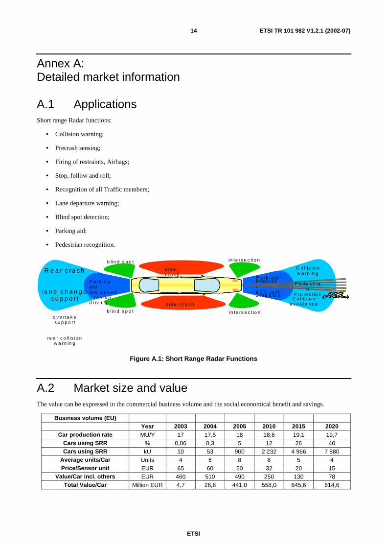
A.1 Applications Short range Radar functions:
• Collision warning;
• Precrash sensing;
• Firing of restraints, Airbags;
• Stop, follow and roll;
• Recognition of all Traffic members;
• Lane departure warning;
• Blind spot detection;
• Parking aid;
• Pedestrian recognition.
in te rs e c t io n
b lin d s p o t in te rs e c t io n
s id e -c ra s h
b l in d s p o t
s id e -c ra s h
P a rk -a id P re c ra sh A C C w ith S to p & G o
C o ll is io n w a rn in g
P e d e s tr ia
n P ro te c tio n
C o l l is io n a v o id a n c e
P a rk in g a id lo w s p e e d b a c k -u p d r iv in g
R e a r c ra s h
la n e c h a n g e s u p p o r t
o v e r ta k e s u p p o r t
re a r c o llis io n w a rn in g
Figure A.1: Short Range Radar Functions
A.2 Market size and value The value can be expressed in the commercial business volume and the social economical benefit and savings.
Business volume (EU) Year 2003 2004 2005 2010 2015 2020
Car production rate MU/Y 17 17,5 18 18,6 19,1 19,7 Cars using SRR % 0,06 0,3 5 12 26 40 Cars using SRR kU 10 53 900 2 232 4 966 7 880
Average units/Car Units 4 6 8 6 5 4 Price/Sensor unit EUR 65 60 50 32 20 15
Value/Car incl. others EUR 460 510 490 250 130 78 Total Value/Car Million EUR 4,7 26,8 441,0 558,0 645,6 614,6
ETSI
ETSI TR 101 982 V1.2.1 (2002-07) 15
Socio-economic benefit
Investigations of the automotive industry were made, which identify the following social economical benefit resulting from road accidents or avoidance thereof. (E.g. in Germany 68 Billion DM).
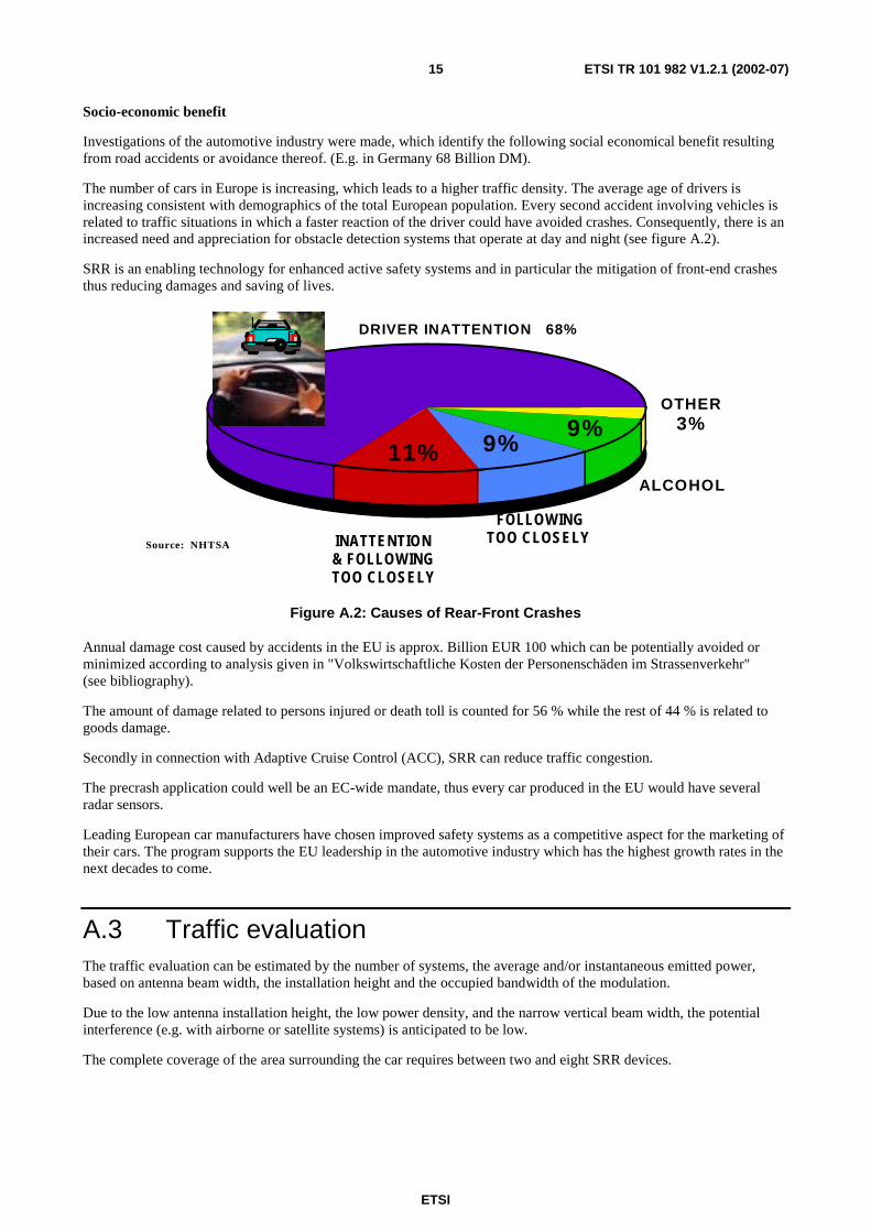
The number of cars in Europe is increasing, which leads to a higher traffic density. The average age of drivers is increasing consistent with demographics of the total European population. Every second accident involving vehicles is related to traffic situations in which a faster reaction of the driver could have avoided crashes. Consequently, there is an increased need and appreciation for obstacle detection systems that operate at day and night (see figure A.2).
SRR is an enabling technology for enhanced active safety systems and in particular the mitigation of front-end crashes thus reducing damages and saving of lives.
INATTENTION & FOLLOWING TOO CLOSELY
Source: NHTSA
DRIVER INATTENTION 68%
OTHER 3%
ALCOHOL
9%
FOLLOWING TOO CLOSELY
9% 11%
Figure A.2: Causes of Rear-Front Crashes
Annual damage cost caused by accidents in the EU is approx. Billion EUR 100 which can be potentially avoided or minimized according to analysis given in "Volkswirtschaftliche Kosten der Personenschäden im Strassenverkehr" (see bibliography).
The amount of damage related to persons injured or death toll is counted for 56 % while the rest of 44 % is related to goods damage.
Secondly in connection with Adaptive Cruise Control (ACC), SRR can reduce traffic congestion.
The precrash application could well be an EC-wide mandate, thus every car produced in the EU would have several radar sensors.
Leading European car manufacturers have chosen improved safety systems as a competitive aspect for the marketing of their cars. The program supports the EU leadership in the automotive industry which has the highest growth rates in the next decades to come.
A.3 Traffic evaluation The traffic evaluation can be estimated by the number of systems, the average and/or instantaneous emitted power, based on antenna beam width, the installation height and the occupied bandwidth of the modulation.
Due to the low antenna installation height, the low power density, and the narrow vertical beam width, the potential interference (e.g. with airborne or satellite systems) is anticipated to be low.
The complete coverage of the area surrounding the car requires between two and eight SRR devices.
ETSI
ETSI TR 101 982 V1.2.1 (2002-07) 16
Annex B: Technical information
B.1 Detailed technical description Carrier modulated UWB Radar needs a narrow band allocation for the residual carrier below -10 dBm. Due to ageing and temperature drift the slot should be in the order of 100 MHz, which is fulfilled by the given 24 GHz SRD band. The narrow band CW mode, required for Doppler speed measurements, is completely covered by the SRD band as well, with a minimum required power of 10dBm eirp. The UWB modulation mode requires a width of 5 GHz to meet separation requirements. The discrete residual carrier spike in pulsed mode is due to a finite AM index (finite switch isolation). It is calculated as Ppeak dB - isolationdB = 20 dBm - 30 dB = -10 dBm residual carrier.
The carrier allocation has to be within an international ISM band due to unlicensed operation and large volumeThere are several wideband modulation technologies as known from spread spectrum technologies, which can be used for short-range radar systems.
Overview of SS Systems for Automotive Radar:
A spread spectrum (SS) signal being "spread" over a large bandwidth can coexist with narrowband signals only adding a slight increase in the noise floor that the narrowband receivers see. As for the spread spectrum receiver, it does not see the narrowband signals since it is listening to a much wider bandwidth at a prescribed code sequence. There are three basic types of spread spectrum techniques usable for automotive low cost carrier based radar devices, which also might be combined in hybrid concepts:
1) PN-PSK (Pseudonoise coded phase shift keying)
The carrier phase of the continuously transmitted sinusoidal signal is changed according to a pseudorandom code sequence. The pseudorandom code sequence has a fixed length, which is repeated after a given number of bits. The inverse of the duration of a single bit of the code sequence is called the chip rate, measured in chips per second (cps). The occupied Bandwidth depends upon the chip rate. At the receiver, the information is recovered by multiplying the signal with a locally generated replica of the code sequence. Due to a finite phase shift precision a certain degree of a residual carrier remains, even when a balanced code is applied. A smoothed spectral density is achieved by the spread of the base signal due to the PN code presenting a noise-like signal.
2) PN-FH (Pseudonoise Frequency Hopping)
In frequency hopping systems, the carrier frequency of the transmitted sinusoidal signal hops over a defined frequency range according o a pseudo random code sequence. The frequency hopping sequences are dictated by the code sequence. The receiver tracks these changes and produces a constant IF signal. The occupied Bandwidth is equal to the total frequency shift utilized by the steps. A smoothed spectral density instead of a discrete comb line spectrum is achieved by applying further pulse modulation during each dwell time in a given channel.
3) PN-PPM (Pseudonoise Pulse position Modulation)
- The pulse repetition period of a pulsed RF carrier is varied in a pseudorandom manner by a coded sequence. The occupied bandwidth is related to the pulse duration. Due to a finite amplitude modulation, a residual carrier leakage is transmitted between the pulses. The "Time of flight" measurement is based on an "equivalent time sampling" principle, which correlates an internal delayed pulse series with the received pulse series delayed by propagation.
- High receiver processing gain can be achieved due to pulse correlation and integration), which allows ultralow eirp.
- A smoothed spectral power distribution is achieved due to pseudorandomized pulse repetition via modulation of the pulse repetition frequency or FM of the carrier.
ETSI
ETSI TR 101 982 V1.2.1 (2002-07) 17
A further spreading of a pulse modulated signal can be achieved by additional FM of the carrier during the pulse (e.g. a pulse compression with a linear FM Chirp). The same effect can be obtained by discrete phase shifts of the pulse according to a barker code.
All these SS types - including further concepts optimized for communication channels- have the following advantages and disadvantages in common:
Advantages:
• Resists intentional and non-intentional interference of narrowband and to a degree wideband emissions.
• Reduces or eliminates multipath effects.
• Improve spectrum efficiency by permitting sharing of the same bands.
• Individual sensor privacy due to the pseudo random code sequence (code division multiplexing (CDMA)).
Disadvantages:
• Larger bandwidth (BW) but at lower power densities.
• More complex implementation.
The larger or relative bandwidth inefficiency does not really apply for the automotive usage of SS radar systems. This stems from the fact that for range accuracy and target separation capability only the absolute bandwidth (or its reciprocal, the pulse duration) is relevant and not the information rate of the binary message (or the PN code, respectively). Indeed the information transmitted contains only the transmitter-specific pseudo-noise sequence and no varying data messages.
Independent from the modulation scheme, the eirp of all SS systems shall be in conformance to the common eirp mask as defined later.
The basic transmitter block diagrams and the spectra of the different automotive SRR systems are shown in figures B.1 to B.6.
The following chapters are an excerpt of documents submitted to WGSE/SE24 under the following URL links:
1) http://ftp.ero.dk/wgse/Se24/SE24_M14_Jan_02_London,/M14_05RO_SE24_24G_System-Tyco.pdf
2) http://ftp.ero.dk/wgse/Se24/SE24_M14_Jan_02_London,/M14_17_R0_SE24_24G_SRR-Bosch-Transmitter-Characterization%20.doc
3) http://ftp.ero.dk/wgse/Se24/SE24_M14_Jan_02_London,/M14_14R0_SE24_WI02_01-24Ghz_System_SV.pdf
All three documents above describe typical operating parameters with proposed minimum and maximum concepts regarding some specific parameters. The primary parameter set that best characterizes the allowed transmission power is not yet defined and is a topic of the compatibility study for 24 GHz SRR systems. One possible solution for a primary parameter set is the definition of a transmission mask for mean and peak power. It should be possible to derive all other secondary parameter values like duty factor, PRF, etc. from these primary parameter set.
ETSI
ETSI TR 101 982 V1.2.1 (2002-07) 18
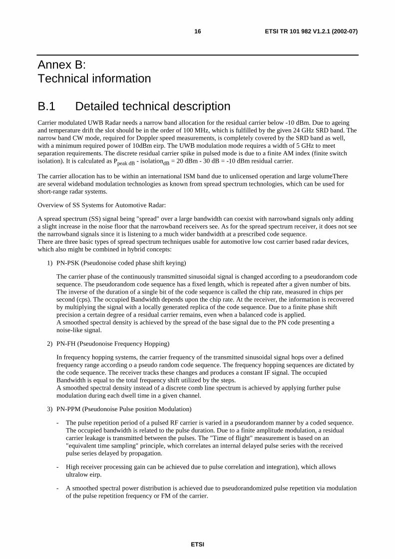
Figure B.1: Typical PN-PPM Block Diagram
/100 kHz
Figure B.2: Measured average spectral eirp density PN-PPM Spectrum @ 100 kHz RBW
The RBW of 100 kHz for this plot was chosen to clearly show the evenly distributed spectral eirp density in case of pulse position modulation (Dithering). The max. PSD is measured to -45 dBm in 100 kHz = -95 dBm/Hz or -35 dBm in 1 MHz reference bandwidth.
The transmitter mask in the centre are at or below the spurious limit of EN 300 440-1 (-30 dBm in 1 MHz, equivalent -40 dBm/100 kHz (green line)). Outside the ±2,5 GHz the mask is reduced below - 50 dBm in 1 MHz, equivalent -60 dBm/100 kHz.
ETSI
ETSI TR 101 982 V1.2.1 (2002-07) 19
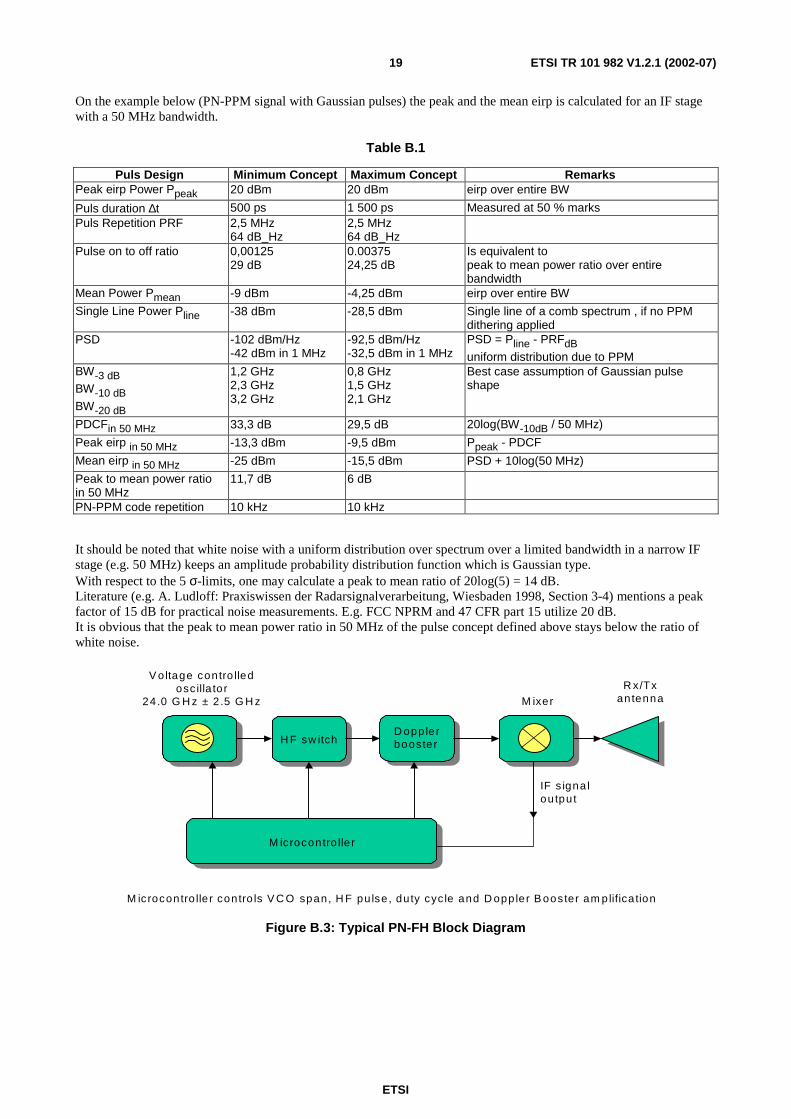
On the example below (PN-PPM signal with Gaussian pulses) the peak and the mean eirp is calculated for an IF stage with a 50 MHz bandwidth.
Table B.1
Puls Design Minimum Concept Maximum Concept Remarks Peak eirp Power Ppeak 20 dBm 20 dBm eirp over entire BW
Puls duration ∆t 500 ps 1 500 ps Measured at 50 % marks Puls Repetition PRF 2,5 MHz
64 dB_Hz 2,5 MHz 64 dB_Hz
Pulse on to off ratio 0,00125 29 dB
0.00375 24,25 dB
Is equivalent to peak to mean power ratio over entire bandwidth
Mean Power Pmean -9 dBm -4,25 dBm eirp over entire BW
Single Line Power Pline -38 dBm -28,5 dBm Single line of a comb spectrum , if no PPM dithering applied
PSD -102 dBm/Hz -42 dBm in 1 MHz
-92,5 dBm/Hz -32,5 dBm in 1 MHz
PSD = Pline - PRFdB uniform distribution due to PPM
BW-3 dB
BW-10 dB
BW-20 dB
1,2 GHz 2,3 GHz 3,2 GHz
0,8 GHz 1,5 GHz 2,1 GHz
Best case assumption of Gaussian pulse shape
PDCFin 50 MHz 33,3 dB 29,5 dB 20log(BW-10dB / 50 MHz)
Peak eirp in 50 MHz -13,3 dBm -9,5 dBm Ppeak - PDCF
Mean eirp in 50 MHz -25 dBm -15,5 dBm PSD + 10log(50 MHz)
Peak to mean power ratio in 50 MHz
11,7 dB 6 dB
PN-PPM code repetition 10 kHz 10 kHz
It should be noted that white noise with a uniform distribution over spectrum over a limited bandwidth in a narrow IF stage (e.g. 50 MHz) keeps an amplitude probability distribution function which is Gaussian type. With respect to the 5 σ-limits, one may calculate a peak to mean ratio of 20log(5) = 14 dB. Literature (e.g. A. Ludloff: Praxiswissen der Radarsignalverarbeitung, Wiesbaden 1998, Section 3-4) mentions a peak factor of 15 dB for practical noise measurements. E.g. FCC NPRM and 47 CFR part 15 utilize 20 dB. It is obvious that the peak to mean power ratio in 50 MHz of the pulse concept defined above stays below the ratio of white noise.
R x/Txantenna
V oltage contro lledosc illa tor
24.0 G H z ± 2 .5 G H z M ixer
IF s igna loutput
M icrocontro lle r contro ls V C O span, H F pu lse , duty cyc le and D oppler B ooster am plifica tion
H F sw itchD opplerbooster
M icrocontro lle r
Figure B.3: Typical PN-FH Block Diagram
ETSI
ETSI TR 101 982 V1.2.1 (2002-07) 20
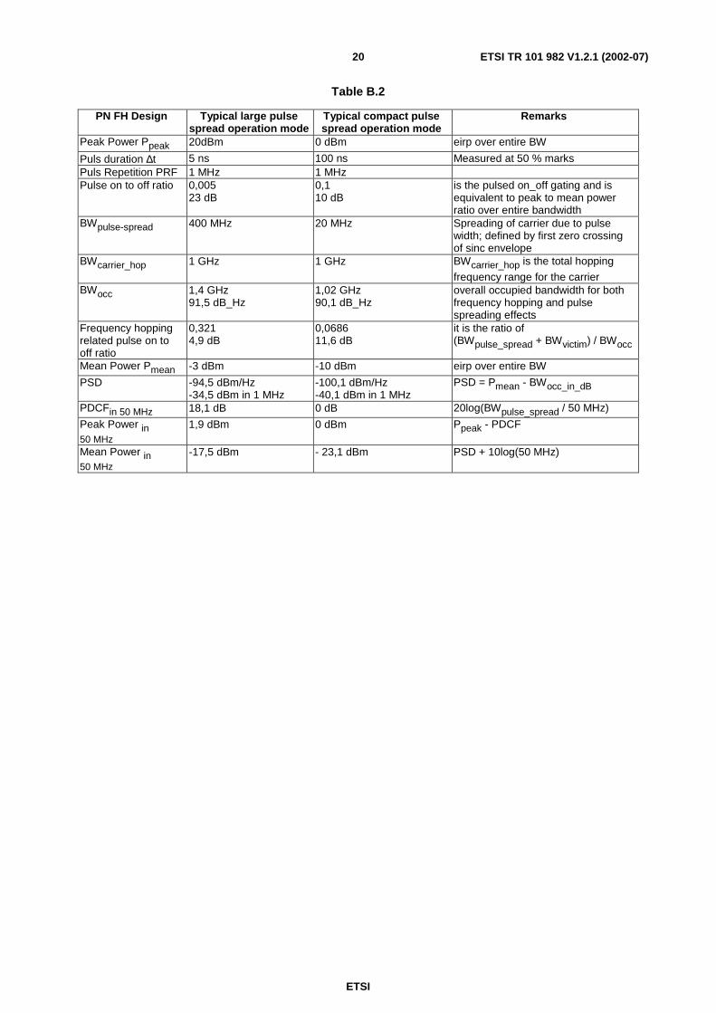
Table B.2
PN FH Design Typical large pulse spread operation mode
Typical compact pulse spread operation mode
Remarks
Peak Power Ppeak 20dBm 0 dBm eirp over entire BW
Puls duration ∆t 5 ns 100 ns Measured at 50 % marks Puls Repetition PRF 1 MHz 1 MHz Pulse on to off ratio 0,005
23 dB 0,1 10 dB
is the pulsed on_off gating and is equivalent to peak to mean power ratio over entire bandwidth
BWpulse-spread 400 MHz 20 MHz Spreading of carrier due to pulse width; defined by first zero crossing of sinc envelope
BWcarrier_hop 1 GHz 1 GHz BWcarrier_hop is the total hopping
frequency range for the carrier BWocc 1,4 GHz
91,5 dB_Hz 1,02 GHz 90,1 dB_Hz
overall occupied bandwidth for both frequency hopping and pulse spreading effects
Frequency hopping related pulse on to off ratio
0,321 4,9 dB
0,0686 11,6 dB
it is the ratio of (BWpulse_spread + BWvictim) / BWocc
Mean Power Pmean -3 dBm -10 dBm eirp over entire BW
PSD -94,5 dBm/Hz -34,5 dBm in 1 MHz
-100,1 dBm/Hz -40,1 dBm in 1 MHz
PSD = Pmean - BWocc_in_dB
PDCFin 50 MHz 18,1 dB 0 dB 20log(BWpulse_spread / 50 MHz)
Peak Power in 50 MHz
1,9 dBm 0 dBm Ppeak - PDCF
Mean Power in 50 MHz
-17,5 dBm - 23,1 dBm PSD + 10log(50 MHz)

ETSI
ETSI TR 101 982 V1.2.1 (2002-07) 21
NOTE: Doppler booster on, eirp mean power ca. 17 dBm.
Figure B.4: Measured Doppler Spectrum of a typical PN-FH signal at 24.125 GHz
Remarks: For motion detection by Doppler operation the PN-FH radar systems operates within the SRD band pursuant to the limits in CEPT/ERC Recommendation 70-03 [1], annex 1 or 6.
²Ø
²Ø
delay unit
code generator
receive
transmit
LO
receive code
transmit code data
carrier with "data" sidebands
data
I
Q
target
Figure B.5: Typical PN-PSK Block Diagram
ETSI
ETSI TR 101 982 V1.2.1 (2002-07) 22
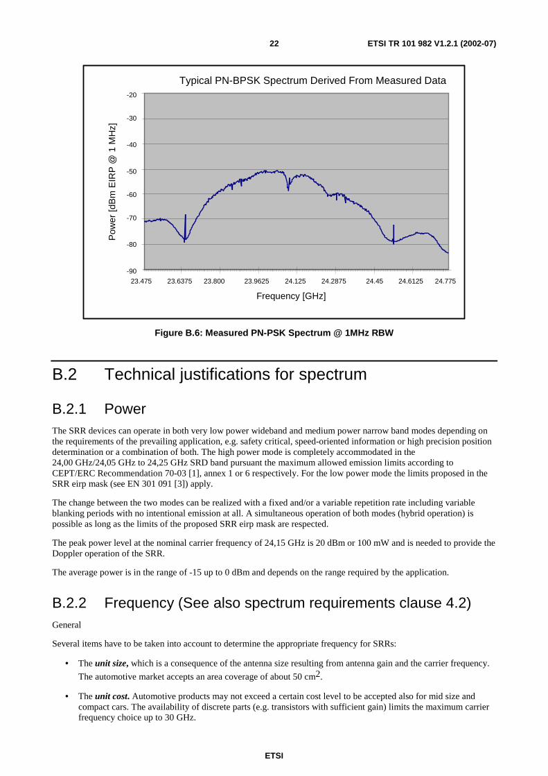
Typical PN-BPSK Spectrum Derived From Measured Data
-90
-80
-70
-60
-50
-40
-30
-20
Frequency [GHz]
Pow
er [d
Bm
EIR
P @
1 M
Hz]
24.125 24.2875 24.45 24.612523.9625 24.77523.80023.637523.475
Figure B.6: Measured PN-PSK Spectrum @ 1MHz RBW
B.2 Technical justifications for spectrum
B.2.1 Power The SRR devices can operate in both very low power wideband and medium power narrow band modes depending on the requirements of the prevailing application, e.g. safety critical, speed-oriented information or high precision position determination or a combination of both. The high power mode is completely accommodated in the 24,00 GHz/24,05 GHz to 24,25 GHz SRD band pursuant the maximum allowed emission limits according to CEPT/ERC Recommendation 70-03 [1], annex 1 or 6 respectively. For the low power mode the limits proposed in the SRR eirp mask (see EN 301 091 [3]) apply.
The change between the two modes can be realized with a fixed and/or a variable repetition rate including variable blanking periods with no intentional emission at all. A simultaneous operation of both modes (hybrid operation) is possible as long as the limits of the proposed SRR eirp mask are respected.
The peak power level at the nominal carrier frequency of 24,15 GHz is 20 dBm or 100 mW and is needed to provide the Doppler operation of the SRR.
The average power is in the range of -15 up to 0 dBm and depends on the range required by the application.
B.2.2 Frequency (See also spectrum requirements clause 4.2) General
Several items have to be taken into account to determine the appropriate frequency for SRRs:
• The unit size, which is a consequence of the antenna size resulting from antenna gain and the carrier frequency.
The automotive market accepts an area coverage of about 50 cm2.
• The unit cost. Automotive products may not exceed a certain cost level to be accepted also for mid size and compact cars. The availability of discrete parts (e.g. transistors with sufficient gain) limits the maximum carrier frequency choice up to 30 GHz.
ETSI
ETSI TR 101 982 V1.2.1 (2002-07) 23
• Required Bandwidth. Radar range separation is proportional to the occupied bandwidth. Short range applications detecting objects of complex shape need a considerable high separation of a few centimetres.
• Application capability. Automotive electronics needs to find mounting space at the car under conditions which allow for full functionality. Coloured standard bumper material has to be accepted. Such random suffers from absorption loss, which is proportional to the frequency. The reflection loss coming from the metallic particles in the colour is proportional to the 4th power of the frequency. Comparing 77 GHz versus 24 GHz shows an entire transmission loss ratio of more then 20 dB.
• Capability for mass production. This implies the reliable availability of components and a stable and reproducible production processes.
• Available frequency band. Global marketing and use or deployment possibility is a very important issue as well as the compatibility to established services.
The centre frequency is 24,125 GHz with a typical tuning tolerance of ± 0,05 GHz as determined by cost effective frequency stabilization of the oscillator.
B.2.2.1 Unit Size
The antenna size sets a lower limit to the unit size. The automotive short range radars have a horizontal opening of about 70° HPBW and a vertical opening of about 20° HPBW. The horizontal opening cannot be chosen much larger but already corresponds to the emission pattern of a single patch which is comparable to a dipole. The vertical directivity is not tilt too much towards the ground because the system performance would suffer from ground clutter. The same holds for the direction towards the sky which is also avoided to prevent from harmful interference to SRRs with services operating above the ground like Fixed Services, Earth Exploration Satellite Systems and Radio Astronomy.
Antenna gains of about 15 dBi are typical for automotive short range radars.
Figure B.7 shows how the unit size dependence from the operating frequency. It can be seen that frequencies below about 15 GHz result in unacceptable unit sizes. The dominating factor is the size of the antenna arrays (Patches).
Frequency in GHz
10 30 100
100
10
1
Size in cm2
Figure B.7: Unit size versus Frequency
B.2.2.2 Unit Cost factors and cost estimation overview
Advanced car safety systems will need about 10 sensors placed around the car to gain a panoramic view. So these systems are very sensitive to radar sensor cost. The main contribution to the sensor module cost are the material cost and the manufacturing cost.
Components for use up to about 25 GHz are readily available from an established market at fair prices. The component market for applications at significant higher frequencies like e. g. in the automotive band at 76 GHz to 77 GHz is currently not mature and not able to supply automotive volume needs at attractive prices.
ETSI
ETSI TR 101 982 V1.2.1 (2002-07) 24
Radars at about 24 GHz can be manufactured with advanced Printed Circuit Boards on full-automated pick and place assembly lines with soldering technologies mainly established in the automotive industry. Products in the 76 GHz to 77 GHz band need sophisticated manufacturing technologies like high precision flip-chip bonding. Those cause high investment cost and have high cycle time accompanied with low yield.
A very rough estimation sees a single beam 24 GHz radar at about 40 € (OEM price) compared to a single beam 77 GHz radar at about 200 €.
For a multi-sensor system with 10 sensors this would result in 400 € (24 GHz) and 2 000 € (77 GHz) of sensor cost, respectively. So currently a 77 GHz based system is not accepted by the market because of its higher price. Of course we will have a price degradation for 77 GHz components in the future, but acceptable levels for short range applications currently cannot be foreseen. On the other hand the price level of 24 GHz based products is currently accepted for high end platforms. As also 24 GHz technology will see a price degradation, applications in medium sized and compact cars are already visible.
B.2.2.2.1 Required Bandwidth/Range Separation
The automotive short range radar systems need to determine not only radial range but also lateral positions. This is e. g. needed to decide in-path and out-of-path objects with respect to the driver lane and to predict the direction of impact for precrash systems. The radar system calculates lateral position from triangulation with the radial range information from at least two sensors. The accuracy ∆r of the distance reading which is necessary to achieve a lateral accuracy ∆y is given by:
∆r = ∆y × b / 2r
where b is the distance between the two sensors and r the radial range of the object referred to the baseline between the sensors.
Typical values are ∆y = 20 cm, b = 1,5 m and r = 10 m. This results in an accuracy requirement of 1,5 cm. Assuming as a rule of thumb that accuracy can be chosen by a factor of three better than the separation we get an requirement of about 5 cm for the separation.
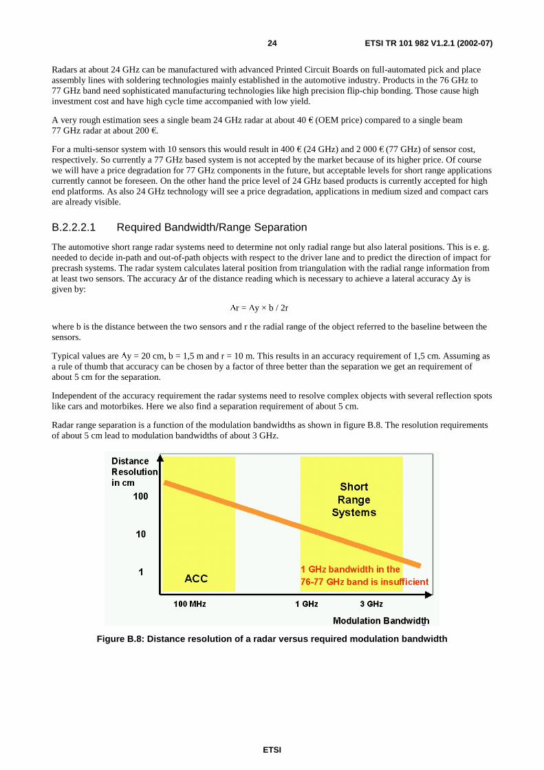
Independent of the accuracy requirement the radar systems need to resolve complex objects with several reflection spots like cars and motorbikes. Here we also find a separation requirement of about 5 cm.
Radar range separation is a function of the modulation bandwidths as shown in figure B.8. The resolution requirements of about 5 cm lead to modulation bandwidths of about 3 GHz.
Figure B.8: Distance resolution of a radar versus required modulation bandwidth

ETSI
ETSI TR 101 982 V1.2.1 (2002-07) 25
B.2.2.2.2 Application Capability
The radar sensors have to be placed at the surface of the cars behind a coverage to keep the aerodynamic resistance value and the styling unchanged. The coverage needs to be sufficiently transparent for the chosen frequency. The plastic materials used at the surface of cars like EPDM, ASA, ABS and PC usually have sufficient transparency. Restrictions are caused by metallic particles in some paints (Raleigh scattering), the thickness of paints (parasitic λ/4 layers) and conductive primers (absorption and reflection) used to enable solvent-free painting processes. Simulation and experiments tell that devices at 24 GHz can live with these application requirements while 77 GHz devices suffer from significant attenuation in excess of 20 dB. In the latter case functionality is no longer achievable. So 77 GHz technology is not generally suitable for mounting behind automotive covers. It furthermore can not be expected, that the car manufacturers could accept any bumper fascia modifications (e.g. transmission windows) to avoid production complexity at limited take rates.
B.2.2.2.3 Mass Production Capability
In addition to low cost conditions the mass production of automotive electronics requires a stable supply situation of really all components (one missing component can stop a whole carline production) and very stable (99,99 % yield) manufacturing processes to guarantee a continuous just in time supply. While this looks achievable in the 24 GHz area it is currently still a significant challenge around 77 GHz because of an immature component market (e. g. no second sourcing for 77 GHz components) and immature manufacturing processes (e. g. high precision flip-chip bonding).
B.2.2.2.4 Frequency Allocation
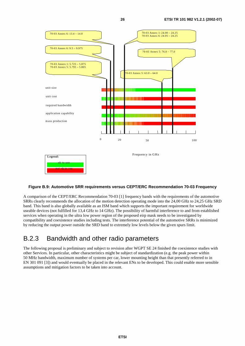
The automotive SRRs need to find space for a bandwidth of > 3 GHz at very low power levels (-30 dBm eirp measured in 1 MHz RBW) in parallel with an allocation of the SRD band with high power levels of +20 dBm eirp measured in 1 MHz RBW located in the centre of the low power SRD band from 24,05 GHz to 24,25 GHz. Figure B.9 illustrates the actual CEPT/ERC Recommendation 70-03 [1] frequency allocation for the different bands. In addition the automotive application needs a globally available frequency allocation.
ETSI
ETSI TR 101 982 V1.2.1 (2002-07) 26
70-03 Annex 5: 63.0 – 64.0
unit size
unit cost
required bandwidth
0 20 50 100
Frequency in GHz
m ass production
application capability
70-03 Annex 1: 5.725 – 5.87570-03 Annex 5: 5.795 – 5.805
70-03 Annex 6: 9.5 – 9.975
70-03 Annex 6: 13.4 – 14.0 70-03 Annex 1: 24.00 – 24.2570-03 Annex 6: 24.05 – 24.25
70-03 Annex 5: 76.0 – 77.0
ok to use
not ok to use
Legend:
Figure B.9: Automotive SRR requirements versus CEPT/ERC Recommendation 70-03 Frequency
A comparison of the CEPT/ERC Recommendation 70-03 [1] frequency bands with the requirements of the automotive SRRs clearly recommends the allocation of the motion detection operating mode into the 24,00 GHz to 24,25 GHz SRD band. This band is also globally available as an ISM band which supports the important requirement for worldwide useable devices (not fulfilled for 13,4 GHz to 14 GHz). The possibility of harmful interference to and from established services when operating in the ultra low power region of the proposed eirp mask needs to be investigated by compatibility and coexistence studies including tests. The interference potential of the automotive SRRs is minimized by reducing the output power outside the SRD band to extremely low levels below the given spurs limit.
B.2.3 Bandwidth and other radio parameters The following proposal is preliminary and subject to revision after WGPT SE 24 finished the coexistence studies with other Services. In particular, other characteristics might be subject of standardization (e.g. the peak power within 50 MHz bandwidth, maximum number of systems per car, lower mounting height than that presently referred to in EN 301 091 [3]) and would eventually be placed in the relevant ENs to be developed. This could enable more sensible assumptions and mitigation factors to be taken into account.
ETSI
ETSI TR 101 982 V1.2.1 (2002-07) 27
S
24 GHz SRD Band
22,625 GHz 25 , 625 GHz
SRR Carrier
EIRP
dBm/MHz
+ 20
+ 10
0
- 10
- 2 0
- 3 0
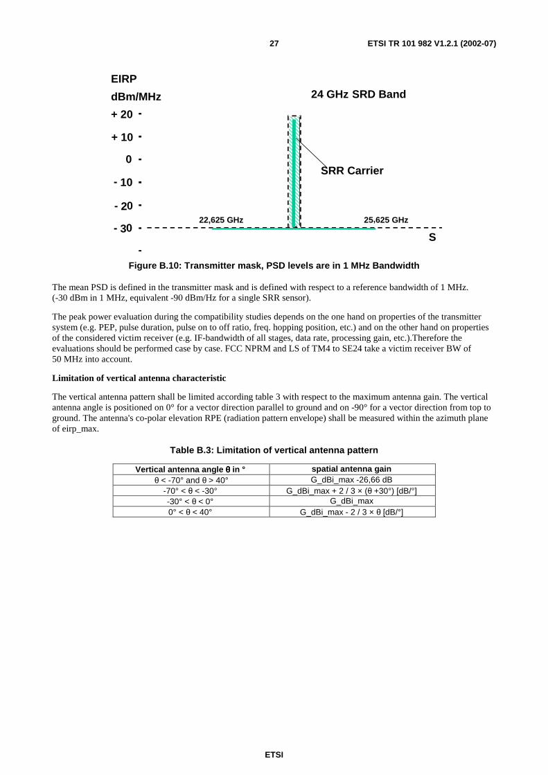
Figure B.10: Transmitter mask, PSD levels are in 1 MHz Bandwidth
The mean PSD is defined in the transmitter mask and is defined with respect to a reference bandwidth of 1 MHz. (-30 dBm in 1 MHz, equivalent -90 dBm/Hz for a single SRR sensor).
The peak power evaluation during the compatibility studies depends on the one hand on properties of the transmitter system (e.g. PEP, pulse duration, pulse on to off ratio, freq. hopping position, etc.) and on the other hand on properties of the considered victim receiver (e.g. IF-bandwidth of all stages, data rate, processing gain, etc.).Therefore the evaluations should be performed case by case. FCC NPRM and LS of TM4 to SE24 take a victim receiver BW of 50 MHz into account.
Limitation of vertical antenna characteristic
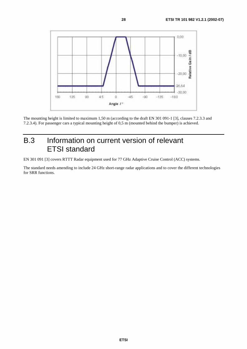
The vertical antenna pattern shall be limited according table 3 with respect to the maximum antenna gain. The vertical antenna angle is positioned on 0° for a vector direction parallel to ground and on -90° for a vector direction from top to ground. The antenna's co-polar elevation RPE (radiation pattern envelope) shall be measured within the azimuth plane of eirp_max.
Table B.3: Limitation of vertical antenna pattern
Vertical antenna angle θθθθ in ° spatial antenna gain θ < -70° and θ > 40° G_dBi_max -26,66 dB
-70° < θ < -30° G_dBi_max + 2 / 3 × (θ +30°) [dB/°] -30° < θ < 0° G_dBi_max 0° < θ < 40° G_dBi_max - 2 / 3 × θ [dB/°]
ETSI
ETSI TR 101 982 V1.2.1 (2002-07) 28
The mounting height is limited to maximum 1,50 m (according to the draft EN 301 091-1 [3], clauses 7.2.3.3 and 7.2.3.4). For passenger cars a typical mounting height of 0,5 m (mounted behind the bumper) is achieved.
B.3 Information on current version of relevant ETSI standard
EN 301 091 [3] covers RTTT Radar equipment used for 77 GHz Adaptive Cruise Control (ACC) systems.
The standard needs amending to include 24 GHz short-range radar applications and to cover the different technologies for SRR functions.
ETSI
ETSI TR 101 982 V1.2.1 (2002-07) 29
Annex C: Expected compatibility issues
C.1 Coexistence studies (if any)
Primary Services in the range of 21,625 GHz to 26,625 GHz:
- Fixed Links;
- Astronomy;
- Space research;
- Inter Satellite;
- Mobile;
- Earth exploration-Satellite.
Secondary services:
- SRD's operating in the ISM band;
- Amateur radio;
- Amateur Satellite.
Regulatory issues and primary, (or secondary) services concerns:
The SRR frequency operating range required for the UWB emissions outside the SRD band is in conflict with the ITU RR 5.340 footnote which prohibits "all emissions" in the passive band from 23,6 to 24,0 GHz. A discussion, interpretation and possible new rule-making of this regulatory issue falls into the competence of European working groups FM, RR, SE and SE 21 (which is the link body to ITU-R SG1 WP1A and WP1B). Also, the definition of spurious and out-of-band emissions for UWB systems requires clarification to be conducted by SE, and SE 21 in cooperation with ETSI ERM TG31A and TG31B.
It is well understood that without clarification of the regulatory issue, the operation of the 24 GHz SRR system as reflected in the draft standard EN 301 091 [3] is pending. For the case that the regulatory framework allows emissions at certain low levels in the passive band, the limits elaborated in the compatibility study for SRR systems should apply and be defined in the Draft Standard.
Prior to the decisions made concerning the regulatory topics, ECC has approved a practical analysis and coexistence study in SE to determine the appropriate transmission mask for SRR systems that avoids harmful interference with all concerned services.
C.2 Current ITU allocations Same as under clause C.1 of the present document, plus radio navigation.
C.3 Sharing issues Compliance evaluation and studies are to be completed for sharing with services under clauses C.1 and C.2 of the present document. Especially the fixed link and passive services require sharing studies.
ETSI
ETSI TR 101 982 V1.2.1 (2002-07) 30
Annex D: Item check lists (remaining Items)
1) Approval of S.R. Doc R1 RM/ERM and forward to SE24 (for information).

ETSI
ETSI TR 101 982 V1.2.1 (2002-07) 31
Annex E: Bibliography
• The EU Approach to Road Safety and Intelligent Transport systems (ITS), EU Commission Unit INFSO/B/5, Fotis Karamamitsos, http://www.cordis.lu/ist/ka1.
• RESPONSE, Project TR4022, Advanced Driver assistance Systems, System safety and driver performance. http://www.cordis.lu/telematics/tap_transport/research/projects/response.html.
• Prof. Peter Knoll, Martin Reiche, Robert Bosch GmbH, "Short Range Automotive Radar (SRR) ERO/ERC workshop on regulatory issues regarding introduction of UWB in Europe. 20 March 2001, - RegTP in Mainz. http://www.ero.dk/eroweb/srd/SRD-UWB.htm.
• Bundesanstalt für Strassenwesen (BAST), "Volkswirtschaftliche Kosten der Personenschäden im Strassenverkehr", Publication of BAST, Issue M102, January 1999, Authors Herbert Baum, K-J Höhnscheid, University of Cologne.
• ETSI EN 300 440-1-1: "Electromagnetic compatibility and Radio spectrum Matters (ERM); Short range devices; Radio equipment to be used in the 1 GHz to 40 GHz frequency range; Part 1: Technical characteristics and test methods".
• "The "Sensitive" Automobile -Bosch Sensors for Complete Environmental Sensing". Dr. Martin Zechnall, Robert Bosch GmbH. Speech to the 55th International Automotive Press Conference, April 2001 in Boxberg.
• Directive 1999/5/EC of the European Parliament and of the Council of 9 March 1999 on radio equipment and telecommunications terminal equipment and the mutual recognition of their conformity (R&TTE Directive).
• IST-19910107, PROTECTOR (Preventive safety for unprotected road users).
NOTE: http://dbs.cordis.lu/cordis-cgi/srchidadb?ACTION=D&SESSION=40222002-7-10&DOC=8
• ITS, Mobile information society, Advanced driver assistance systems.
NOTE: ftp://ftp.cordis.lu/pub/telematics/docs/tap_transport/adas.pdf
ETSI
ETSI TR 101 982 V1.2.1 (2002-07) 32
History
Document history
V1.1.1 July 2001 Publication
V1.1.2 August 2001 Publication
V1.2.1 July 2002 Publication


![ß-Lapachone-mediatedApoptosis in Human …...(CANCER RESEARCH 55. 3706-3711, September 1, 1995] Advances in Brief ß-Lapachone-mediatedApoptosis in Human Promyelocytic Leukemia](https://static.fdocuments.us/doc/165x107/5e6088b1a689c13f9a142c93/f-lapachone-mediatedapoptosis-in-human-cancer-research-55-3706-3711-september.jpg)