ООО «НОВАТЕК-ЭЛЕКТРО»- exceeding the negative sequence current threshold; - phase...
32
NOVATEK-ELECTRO LTD Intellectual Industrial Electronics ELECRTIC MOTORS UNIVERSAL PROTECTION DEVICE UBZ-302 OPERATING MANUAL Review the Operating manual before using the unit. Store the unit in the operating environment for 2 hours before switching to the mains. www.novatek-electro.com
Transcript of ООО «НОВАТЕК-ЭЛЕКТРО»- exceeding the negative sequence current threshold; - phase...

NOVATEK-ELECTRO LTDIntellectual Industrial Electronics
ELECRTIC MOTORS UNIVERSAL PROTECTION DEVICE
UBZ-302
OPERATING MANUAL
Review the Operating manual before using the unit. Store the unit in the operating environment for 2 hours before switching to the mains.
www.novatek-electro.com

- 2 -
UBZ-302 NOVATEK-ELECTRO
Contents
1 DESCRIPTION AND DESIGN ...………………………………………………………………………………………... 3 1.1 PURPOSE …...………………………………………………………………………………………………………….. 3 1.1.1 General Information………………………………………………………………………………….…………….. 3 1.1.2 Changes in the UBZ Specifications and Operation Depending on the Software Version ….……………… 3 1.1.3 Limitations of UBZ Application and Correct Choice of Parameters ..………………………………………… 4 1.1.4 List of Abbreviations ………………...…………………………………………………………………………….. 4 1.2 TECHNICAL SPECIFICATIONS …………………………………………..…………………………………………. 4 1.2.1 Main Technical Specifications …………………………………………...…………………………….…………. 4 1.2.2 Measured and Calculated Parameters ……………………………………..………………………...…………. 5 1.2.3 Programmable parameters …………………………………………………………………………..……………. 7 1.2.4 UBZ Controls and Dimensions ……………………………………………………………………………………. 12 1.2.5 Protection Functions ……………………………………………………………………………………………….. 13 1.2.5.1 Protection Types ………………………………………………………………………………………………… 13 1.2.5.2 Overcurrent Protection …………………………………………………………………………………………. 13 1.2.5.3 Ground Fault Protection ………………………………………………………………………………………... 14 1.2.5.4 Negative Sequence Current Protection ……………….……………………………………………………… 14 1.2.5.5 Undercurrent Phase Protection …………………………………...………………………………………….. 14 1.2.5.6 Delayed Start and Rotor Blocking …………………………………………………………………………….. 14 1.2.5.7 Thermal Overload Protection ………………………………………………...………………………………... 15 1.2.5.8 Coil Overheating Protection ……………………………………………………..…………………………….. 16 1.2.5.9 Voltage Protection ………………………………………………………………………..…………………….. 16 1.2.5.10 Phase Sequence Protection ………………………………………………………………………..………... 16 1.2.5.11 Motor Coil Insulation Minimal Resistance …………………………………………………………………... 16 1.2.5.12 Phase Loss Protection………………………………………………………………………………………… 16 1.2.3.13 Control of external MS working order ……………………………………………………………………….. 16 1.3 PACKAGING CONTENTS …………………………………………………………………………………………….. 17 1.4 FEATURES AND OPERATION ….…………………………………………………………………………………… 17 2 INTENDED USAGE …………………………………………..………………………………………………………….. 17 2.1 SAFETY …………………………………………………………………………..……………………………………... 17 2.2 DEVICE CONTROLS ………………………………………………………………………………………………….. 17 2.2.1 UBZ Control Modes ………...……………………………………………………………………………………… 17 2.2.2 Keypad Locked ……………………………………..……………………………………………………………… 17 2.2.3 Keypad Unlocked ………………………………………………………………………………………………….. 17 2.2.3.1 MSM Mode …………………………………………………………………..………………………………….. 17 2.2.3.2 Editing and Viewing User-Level Parameters ……………………………………………….……………….. 18 2.2.3.3 Editing and Viewing Engineer-Level Parameters …………………………………………………..………. 18 2.2.4 Reset to Factory Settings …………………………………………………………………………………………. 18 2.2.5 UBZ ALARMS RESET on the front panel ……………………………………………………………………….. 18 2.3 PREPARING UBZ FOR OPERATION ……………………………………………………………………………….. 19 2.4 INTENDED USAGE ……………………………………………………………………………………………………. 19 2.4.1 UBZ Operation Before Load Relay Activation …...…………………………………………………….……….. 19 2.4.2 UBZ Operation After Load Relay Activation and Motor Energizing ……...…………………………………… 20 2.4.3 Functional Relay Operation ………………………………………………………………………………………. 21 2.4.4 Using the RS-232/RS-485 Interface with the MODBUS Protocol, RTU Mode ………...……………………. 21 2.4.5 Fault Status System ………………………………………………………………………………………..……... 26 2.4.6 Fault Status Log ………………………………………………………………………………….......................... 27 2.4.7 Controlling the Motor Using the UBZ Front Panel ...................................................................................... 27 2.4.8 Controlling the Motor Using the Analog Inputs …………………………………………..…………………...… 27 3 TECHNICAL MAINTENANCE ………………………………………………………………………………………….. 27 3.1 SAFETY PRECAUTIONS …………………………………………………………………………………………….. 27 3.2 TECHNICAL MAINTENANCE PROCEDURE ………………………………………………………………………. 28 4 TRANSPORTATION AND STORAGE ……………………………………………………………..………………..… 28 5 TERMS OF SERVICE AND MANUFACTURER’S WARRANTY..………………………………………………….. 28 APPENDIX 1 – Time Dependent Current Protection……………………………………….…...…………………….. 29 APPENDIX 2 – Using UBZ to Control Motor with Switching Coil from Star to Delta at the Start …………………. 31

- 3 -
NOVATEK-ELECTRO UBZ-302
1 DESCRIPTION AND DESIGN 1.1 PURPOSE
1.1.1 General Information UBZ-302 Universal Electric Motor Protection Device (UBZ) is designed for continuous monitoring of the circuit
voltage parameters, the RMS values of phase/line currents of three-phase electric equipment, and the electric motor insulation resistance values.
UBZ is designed for protection of asynchronous induction motors ranging from 2.5 kW to 30 kW that use inte-grated current transformers, including in circuits with insulated neutral.
UBZ provides for electric motor protection in case of: - poor quality supply voltage (unacceptable voltage surges, phase loss, incorrect phase sequence and phase
coincidence, phase/line voltage imbalance); - mechanical overloads (symmetrical phase/line current overload); - exceeding the negative sequence current threshold; - phase current imbalance without overload, induced by the insulation fault inside the motor and/or the lead ca-
ble (the current imbalance factor is compared to the voltage imbalance factor using negative sequence); - loss of motor torque ("dry stroke" for pumps) – protection based on the minimal starting and/or operating current; - delayed motor start or rotor locking; - abnormally low insulation level between the fixed coil and frame (testing before motor startup); - ground fault of the stator coil during operation - protection against ground leakage current; - motor thermal overload; - coil overheating (measuring the coil temperature with integrated temperature sensors, or the body tempera-
ture with external temperature sensors). For each protection type, automatic reclosing (ARC) can be enabled or disabled. The device provides for electric equipment protection by means of controlling a magnetic starter (contactor) coil.
The device detects the presence of load currents when the load relay is open (when the load relay is open and the functional relay is in the star-delta mode). In this case the Unit initiates the alarm of external Magnetic Starter (fur-ther in text as MS), which starts the engine, until the unit or the control of engine currents are switched off while the load relay is deactivated.
UBZ provides for electric motor control through the following interfaces: - two analogue inputs – “0-20 mA” and “0-10 V”; - remote control channels (RS-232 and RS-485 interfaces); - buttons on the front panel of the UBZ. Communication - control and parameter transfer via the RS-485 interface using the MODBUS protocol; - control and parameter transfer via the RS-232 interface. NOTE: simultaneous use of RS-485 and RS-232 is not allowed.
To use UBZ with a PC, you can use the “UBZ Control Panel” software, available from the website of NOVATEК-ELECTRO (http://novatek-electro.com/en/software.html).
The UBZ-302 Control Panel software is designed for monitoring the status of UBZ-302 devices and retrieving data from them via the RS-232 or RS-485 interface. The application allows saving (loading) various UBZ settings, collecting data and saving it for further analysis. Saved data can be viewed on a diagram for parameter comparison.
The software’s graphic user interface allows viewing the current status of various UBZ parameters in real-time. The flexible interface design allows any degree of customization.
1.1.2 Changes in the UBZ Specifications and Operation Depending on the Software Version. Version 13 updates: - additional parameters included in the consumed and displayed parameters list: load consumed gross, active
and reactive power; - added motor protection against phase (phases) loss with current control; - added registers (read-only) containing values of the load consumed active power (nominal units) for each
phase; - added capability for remote start and stop of the motor via the RS-232/RS485 interface. Version 15 updates: - corrected error arising when measuring currents over 650А; - when working with external transformers with rated current over 100A, current values (measured and calcu-
lated) are transferred via RS-232/RS485 in amperes. Version 18 updates: - the algorithm of output to indication of isolation resistance with the engine being energized is changed (table
1.4 remark 4). Version 20 updates: - added the option to control the motor using the analogue inputs “0 – 20 mA” and “0 – 10 V”; - increased the reliability of data transfer through the MODBUS interface; - added fault detection of EEPROM destruction;

- 4 -
UBZ-302 NOVATEK-ELECTRO
- changed the algorithm for leaving the menu. In program version 21: - the command "UBZ ALARM RESET” via MODBUS interface is added (item 2.4.4.9) and option of UBZ
ALARM RESET on the front panel is added (item 2.2.5); - the command "UBZ RESTART" ("RESTART") (item 2.4.4.10) is added; - is added the option of UBZ RESET TO FACTORY SETTINGS via MODBUS interface; - is added the option of switching off the engine currents control while the load relay is deactivated.
1.1.3 Limitations of UBZ Application and Correct Choice of Parameters 1.1.3.1 Using Internal Current Transformers. When using internal current transformers, UBZ cannot be used to protect motors with wattage over 30 kW. When measuring motor currents of 63A to 300A, the measurement error does not exceed 5%, while at currents
over 320A, the current transformer core becomes saturated, and the measurement error increases rapidly. Regard-less of the actual current value, the current measured by UBZ will not exceed 400A. Setting up certain programma-ble parameters (maximum current protection, delayed start and rotor locking, thermal overload) without regard to the saturation of current transformers will make protection tripping impossible.
For example, at ind =50 (rated current), i = P =0 (independent delay current protection), i = S =9 (overcurrent protection tripping ratio), the overcurrent protection should trip at 450А. Due to the transformer saturation, the measured value of current will not exceed 380-400A, even in case of a short circuit in the coil and currents of over 1000A, and, therefore, UBZ will not de-energize the motor. In this case (ind=50), the user should set the overcur-rent tripping ratio at a value not exceeding 6.
1.1.3.2 Using External Current Transformers. The rated current of external standard current transformers must be equal or higher than the rated current of the
motor.
1.1.4 List of Abbreviations ARC – automatic reclosing of the output contacts (autoreclosing) MS – magnetic starter PC – personal computer CT – current transformer MMSP – mode with minimal number of setting parameters Itt – rated current of CT (specified when external CT are used. For example, if CT is type Т-0.66 300/5, then Itt
is 300 A) In – rated current of motor. Usually, the current value shown on the motor plate, but a different current value
may be set subject to specific operating conditions.
1.2 TECHNICAL SPECIFICATIONS
1.2.1 Main Technical Specifications An overview is provided in Table 1.1. The main technical specifications are provided in Table 1.2. The parameters of the integrated relay output terminals are shown in Table 1.3.
Table 1.1 - General Information
Item Unit Value
Purpose of device - Control and distribution equipment. Asynchronous motor protection control.
Assembly (mounting) type - mounted on standard 35 mm DIN bar
Protection degree: - device - terminal block
- IP40 IP20
Climate zone category - N3.1 (moderate, indoors)
Operating temperature range С from - 35 to +55
Storage temperature С from - 45 to +70
Pollution degree - III
Overvoltage category - III
Diameter of adapters on terminals mm2
0.5-2
Maximum torque of terminal screws N*M 0.4
Table 1.2 – Main Technical Specifications
Rated supply voltage: three-phase 400/415 V
Mains frequency, Hz 48-62
Rated currents range (when using integrated current transformers), A 5-63
Voltage hysteresis, (phase/line), V 10/17

- 5 -
NOVATEK-ELECTRO UBZ-302
Thermal hysteresis, % of accumulated heat at shutdown 33
Current tripping threshold detection accuracy, % of rated current, ≤ 2
Voltage tripping threshold detection accuracy, V, at least 3
Voltage based phase imbalance detection accuracy, V, at least 3
Minimum operational voltage: - single-phase voltage power supply, with connected neutral wire, V, at least - three-phase power supply voltage, V, no more than
180 450
Main outputs - load relay – two groups of changeover contacts for motor starter control - 8A, 250V at cos φ=1; - functional relay – one group of changeover contacts - 16 A, 250 V at cos φ=1 (relay function assigned by the user)
Analog inputs - two analog inputs for temperature sensors (type Pt100, Ni100,Ni120) - analog input for sensor with 0-10 V output - analog input for sensor with 4 mA (0mA) – 20 mA output - three analog inputs for standard CT with 5A output (type T-0.66 or similar) - input for differential current transformer (zero sequence transformer)
Temperature sensor resolution, С 1
Power consumption (under load), VA, no more than 5,0
Weight, kg, no more than 0,5
Dimensions (figure 1.1) - nine S type modules Mounting – on a standard 35 mm DIN bar Mounting position – any
Table 1.3 – Characteristics of output terminals of integrated relays
Relay Operation mode
Max. current at U~250 V
N of tripping x 1000
Max. com-mutated power
Max. addi-tional alternat-
ing voltage
Max. current at Uconst=30 V
(N of tripping)
functional relay
cos = 0.4
cos = 1.0
5 A 16 A
100 4,000 VA 440/300 V 3 A
load relay cos = 0.4
сos = 1.0
2 A 8 A
100 100
1,000 VA 460 V 3 A (50,000)
UBZ-302 complies with requirements: IEC 60947-1:2004, ІDТ; ІEC 60947-6-2:1992, ІDT; CISPR 11:2004, IDT; IEC 61000-4-2:2001, IDT UBZ-302 conforms to the requirements: Hazardous substances in excess of maximum allowable concentration – absent.
1.2.2 Measured and calculated parameters output to the display device*, their measurement limits and toleranc-
es are provided in Table 1.4. NOTE: - Display devices include: - two three-digit seven-segment indicators on the front panel of UBZ; - PC connected via one of the UBZ interfaces (MODBUS, RS-232).
Table 1.4 – Measured and Calculated Parameters
Measurement Functions Range Accuracy Mnemo-nics
Address Units of measu- rement used for data transfer
Currents 1/10 A******
Phase currents RMS values, A 0.5-630 2% ,
,
100,101, 102
Zero sequence current RMS value, A 0.3-5,0 2% 103
Each phase average current value at the time speci-fied in tSi
,,
104,105, 106
Махimum average current value for each phase ob-tained since the last power on. All average values can be reset using the (RES/MEM/SEL) button at the time of max average current value output for any phase (the new value
<3 Itt > 3 Itt
2% 10%
,
,
107,108, 109
- 6 -
UBZ-302 NOVATEK-ELECTRO
assigned will be the real-time average current value for corresponding phase).
Motor starting current (phase average) Overcurrent (phase average) Start time, sec Start time is time from the moment when all three phase currents exceed 1.2In and up to the moment when the three currents drop below 1.2In. Maximum phase current achieved during this period is the max-imum starting current.
<3 Itt > 3 Itt 0.1-600
2% 10%
110 112 111
1/10 A******
Negative sequence current (current imbalance), A. 0.2-200 5% 113
Voltage
Phase voltages RMS values (defined by connecting zero wire to the UBZ device), V
100-300 3 V ,
,
114,115 116
V
Line voltage RMS values, V 100-475 5 V ,
,
117,118 119
Positive-sequence voltage, V 100-300 3 V 120
Negative-sequence voltage, V 3 -300 3 V 121
Zero-sequence voltage (vector sum of three phase voltages, divided by three), (defined when zero wire is connected to the UBZ device), V.
3-100 3 V 122
Miscellaneous
Sensor 1 temperature (sensor type assigned accord-ing to Table 1.5),°C *
-40 to 100 1°C 123 5,000 – sensor not on 1,000±10– sensor short-circuited 2,000±10– sensor fault
Sensor 2 temperature (sensor type assigned accord-ing to Table 1.5),,
°C *
-40 to 220 1°C 124
Current value at (4-20) mА input, mA 0-25 2% 125 1/100 mA
Voltage value at 0-10 V analog input 0-10 V 2% 126 1/10 V
Equipment operation time counter, days 0-999 127
Mains frequency, Hz 45-65 1% 128 1/10 Hz
Operation time before overload de-energizing (indi-cates time left before protection triggers thermal over-load de-energizing), seconds
0-600 1 s 129 seconds
Time before ARC delay termination, seconds** 0-900 1 s 130 seconds
Wait time after overload de-energizing (indicates wait time before system restart is permitted after being locked by thermal protection), seconds ***
0-900 1 s 131 seconds
Motor insulation resistance, MOhm **** 0-19.9 10% 132 ‘00 kOhm
Motor thermal balance Read-only parameter via RS-232 or RS-485 interface
1,100 thousand corresponds to 100% of accumulated heat at which the motor is de-energized if heat overload tripping is on (p. 1.2.5.7)
133, 134
Gross power, kVA***** 0-5,000 5% 135, 136
‘0 W
Active power, kW***** 0-5,000 5% 137, 138
Reactive power, kVAr***** 0-5,000 5% 139, 140
‘0 W
Phase А voltage/current angle cos*1000 Read-only parameter via RS-232 or RS-485 interface
0-1,000 5% 141, 142
Phase B voltage/current angle cos*1000 Read-only parameter via RS-232 or RS-485 interface
0-1,000 5% 143,144
Phase C voltage/current angle cos*1000 Read-only parameter via RS-232 or RS-485 interface
0-1,000 5% 145,146

- 7 -
NOVATEK-ELECTRO UBZ-302
Table 1.4, continued
* If the temperature value exceeds the specified limit, the value indicator displays an error code as per Table 2.8.
** If automatic reclosing is forbidden, “” is displayed on the indicator. *** If the time before thermal overload safety de-energizing or the wait time before system start permit (ttP) has
not been defined (over 900 sec), “---“ code is displayed. If protection operation is forbidden, “”is displayed.
**** If the motor insulation resistance exceeds 20 MOhm, the value indicator displays code “ “ (numerical “one”
with a point in the higher digit). When the motor is on (power voltage supplied to the motor), the insulation resistance is not defined, and “---“
code is displayed (when the motor insulation measurement circuitry is connected). ***** If the power consumed by the load exceeds 999 kW (kVA, kVAr), then the MW (MVA, MVAr) value is dis-
played on screen with a “”– shaped point in the middle digit. For example, if the display shows “”, it means 3.4 MW (MVA, MVAr). ****** Note. In software version 15, when using external transformers with rated current over 100A, the current val-ues (measured and calculated), except for the zero sequence current (ground fault), are transferred in A, via the RS-232/RS485 interface.
1.2.3 Programmable parameters and their variability ranges are provided in Table 1.5.
Table 1.5 - Programmable parameters
Set and read parame-ters
Mnemon-ics
Min. Max. Factory setting
Operation Ad-dress
Transformers
CT in use 0 1 0 0-using integrated CT 1-using external CT
150
CT rated current, A 20 800 100 For external CT 151
Miscellaneous
Motor rated current, A 0 630 0 0-current value not set: UBZ will not activate load relay (p.2.3.7).
152
Average current meas-urement time, seconds
10 600 60 Time during which the average current value is measured (parameters iS1, iS2, iS3 from Table 1.4)
153
Overcurrent protection
Overcurrent protection type
0 5 0 0-protection with independent time
delay Protection types with dependent time delay: 1-SIT; 2-VIT (LTI); 3-EIT; 4-UIT; 5-RI
154
Overcurrent protection tripping setting value, ratio
0.8 9.0 4.0 Assign the ratio to the motor rated cur-
rent (active at i
= P = 0).
155
Overcurrent protection tripping delay, seconds
0.3 600 10.0 156
Protection permission 0 2 2 0-protection forbidden
1- protection allowed, no ARC after tripping 2- protection allowed, ARC after trip-ping allowed
157
Order of overcurrent protection tripping rela-tive to thermal overload protection
0 1 1 0-protection activated independent of
thermal overload protection 1-in absence of thermal overload, overcurrent is indicated, but the over-load relay is not tripped
158
Protection against ground faults (zero sequence current iF0)
Current fault tripping setting, A
0.3 5.0 0.5 If the parameter is included in the MSM list, the default values are:
0,5 at In50 A; 1.0 at In>50 A
159
Protection tripping de-lay, seconds
0.3 2.0 1.0 160

- 8 -
UBZ-302 NOVATEK-ELECTRO
Set and read parame-ters
Mnemon-ics
Min. Max. Factory setting
Operation Ad-dress
Protection permission 0 2 2 0-protection forbidden 1- protection allowed, no ARC after tripping 2- protection allowed, ARC after trip-ping allowed
161
Negative sequence current protection
Tripping setting, % 5 20 10 Percents of rated current 162
Protection tripping de-lay, seconds
0.3 10.0 5.0 163
Protection permission 0 2 2 0-protection forbidden 1- protection allowed, no ARC after tripping 2- protection allowed, ARC after trip-ping allowed
164
Analysis of causes for negative sequence current protection tripping
Negative sequence cur-rent ratio divided by negative sequence volt-age ratio
2 4 2 165
Analysis permission 0 1 1 0- analysis off 1- analysis on
166
Thermal overload (motor thermal model)
Protection permission 0 2 2 0-protection forbidden 1- protection allowed, no ARC after tripping 2- protection allowed, ARC after trip-ping allowed
167
Double overcurrent over-load protection tripping time, seconds
10 120 60 168
Time increase ratio with a stopped motor
1.0 4.0 1.0 Compensating for the increased cooling time with a stopped motor
169
Undercurrent phase protection
Tripping setting, % 11 90 20 Minimum operating current tripping threshold, % of rated current
170
Protection tripping delay, seconds
1 100 5 171
Protection permission 0 2 2 0-protection forbidden 1- protection allowed, no ARC after tripping 2- protection allowed, ARC after trip-ping allowed
172
Delayed start, rotor blocking
Tripping setting, ratio 1.5 7.0 5.0 Ratio relative to rated current 173
Delayed start protection tripping delay, seconds
1 600 10 Motor start time 174
Rotor blocking protection tripping delay, seconds
0,3 300 1,0 175
Protection permission 0 2 1 0-protection forbidden 1- protection allowed, no ARC after tripping 2- protection allowed, ARC after trip-ping allowed
176
Voltage protection
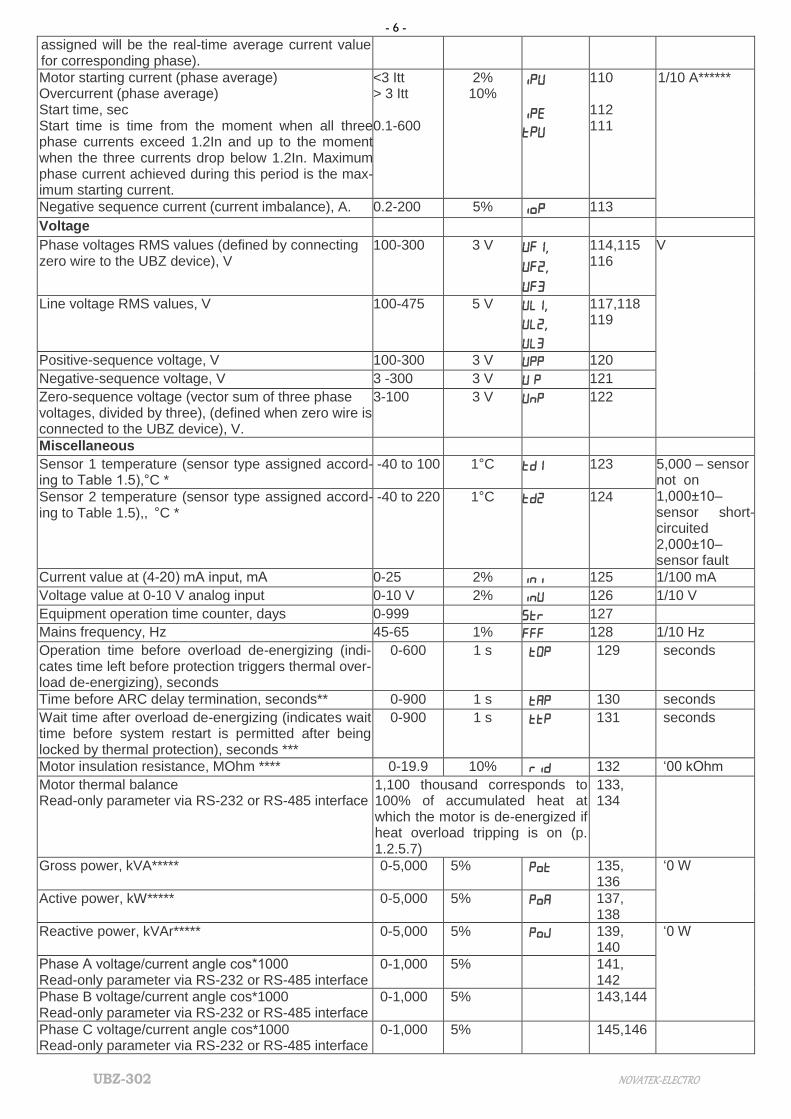
Minimum line voltage, V 270 415 320 177
- 9 -
NOVATEK-ELECTRO UBZ-302
Set and read parame-ters
Mnemon-ics
Min. Max. Factory setting
Operation Ad-dress
Minimum voltage protec-tion tripping delay,seconds
5 30 10 178
Minimum voltage protec-tion permission
0 2 2 0-protection forbidden 1- protection allowed, no ARC after tripping 2- protection allowed, ARC after trip-ping allowed
179
Maximum line voltage , V 330 475 415 180
Maximum line voltage protection tripping delay, seconds
1 10 2 181
Maximum line voltage protection permission
0 1 2 0-protection forbidden
1- protection allowed, no ARC after tripping 2- protection allowed, ARC after trip-ping allowed
182
Line voltage imbalance, V 15 120 35 Negative sequence 183
Line voltage imbalance protection tripping delay, seconds
1 30 5 184
Line voltage imbalance protection permission
0 2 2 0-protection forbidden
1- protection allowed, no ARC after tripping 2- protection allowed, ARC after trip-ping allowed
185
Phase sequence order protection permission
0 2 1 0-protection forbidden 1- protection allowed, no ARC after tripping 2- protection allowed, ARC after trip-ping allowed
186
Motor operation and automatic reclosing (ARC)
ARC time after undercur-rent protection tripping, seconds
0 900 600 187
ARC time, seconds 0 900 5 188
ARC prohibition for all faults (except voltage faults)
0 1 1 0-ARC forbidden 1-ARC allowed The value of Arr applies to all fault types except voltage faults. To forbid ARC after voltage faults, use
the parameters , ,
п
189
Motor operation permis-sion after UBZ power-on
0 2 1 0 – manual motor start using the UBZ front panel 1- motor start after ARC time 2- motor start after 2 seconds
190
Motor control via UBZ front panel
0 3 0 0 - forbidden 1 – motor start allowed 2 – emergency motor stop allowed 3 – motor start and stop allowed (see p. 2.4.7)
191
Temperature control
Temperature sensor 1 type and temperature control permission
0 2 0 0 – off 1- integrated in motor (protection trip-ping happens at sensor resistance over 1.7 kOhm) 2 – PTC (1 kOhm at 25ºС)
192
Motor de-energizing temperature
0 100 80 193
Sensor 1 temperature correction
-9 9 0 194

- 10 -
UBZ-302 NOVATEK-ELECTRO
Set and read parame-ters
Mnemon-ics
Min. Max. Factory setting
Operation Ad-dress
Temperature sensor 2 type and temperature control permission
0 3 0 0 – off 1 – type Pt100 2- type Ni100 3- type Ni120
195
Motor de-energizing temperature
0 220 180 196
Warning temperature 0 220 170 197
Sensor 2 temperature correction
-9 9 0 198
ARC after protection tripping
1 2 2 1- ARC after protection tripping forbid-den 2- ARC after protection tripping allowed
199
Reaction to temperature sensor failure
0 1 0 0- warning and continued operation; 1- warning and motor stop;
200
Motor insulation resistance
Minimum motor insula-tion resistance protection
0 20 5 0-off 5-motor does not start at insulation resistance under 500 kOhm, ARC al-lowed 10- motor does not start at insulation resistance under 1,000 kOhm, ARC allowed 15- motor does not start at insulation resistance under 500 kOhm, ARC for-bidden 20- motor does not start at insulation resistance under 1,000 kOhm, ARC forbidden
201
Miscellaneous
Minimal number of set parameters mode
0 1 1 0-mode activated 1-mode deactivated The mode can only be changed in en-gineer access mode.
202
Indication on UBZ dis-play before motor power-on
0 2 1 0- linear voltage Uab 1-insulation resistance rid 2-ARC countdown
203
Parameter indication mode
0 1 1 0-parameter value displayed continu-ously 1-parameter value displayed during 15 seconds
204
Functional relay opera-tion mode
0 2 0 0-relay used as signaling relay 1- relay used as time relay (closed af-ter a time specified in rrt after the load relay closes) 2-relay used for star-delta motor switching (after time specified in rrt (address 206), the load relay is open, and after time specified in rrt (address 206) + Ftt (address 218), the function-al relay is closed).
205
Timer, seconds 0 300 30 see p. 2 and p.3 in parameter 206
Equipment uptime, days 0
999
0
*uptime transferred in hours if using the MODBUS/RS-232 interface
207
Motor uptime, days 0
999
0
*uptime transferred in hours if using the MODBUS/RS-232 interface
208
User access code 0 9 0 0 – keypad unlocked 1-9 – user password
209
Engineer access code 000 999 123 000 – engineer access granted 000-999 – engineer password
210

- 11 -
NOVATEK-ELECTRO UBZ-302
Set and read parame-ters
Mnemon-ics
Min. Max. Factory setting
Operation Ad-dress
Reset to factory settings 0 1 0 After entering 1 and exiting the pa-rameter setting mode, factory settings are restored
211
Serial interface parameters (RS-485/ RS-232)
UBZ communication ad-dress
1 247 1 212
Transfer rate 0 1 0 0: 9,600 baud; 1: 19,200 baud; The transfer rate only changes after the device is powered off and on again.
213
Adapter reaction to loss of link
0 3 0 0- continued operation, no warning 1- warning, continued operation 2- warning, motor stop, ARC allowed after link restored 3- warning, motor stop, ARC forbidden after link restored
214
Response timeout detec-tion, seconds
0 120 0 0-forbidden 215
UBZ communication via serial channel
0 2 0 0- communication forbidden 1- communication via RS-232 2- communication via MODBUS
216
Device version 21 217
Functional relay mode parameters Star-delta mode.
Switching, seconds 0,1 2,0 0,4 Time between load relay opening and functional relay closing
218
Motor phase (phases) loss, with current control
Phase loss protection tripping delay, seconds
0,3 10 0,5 219
Protection permission 0 2 1 0-protection forbidden 1- protection allowed, no ARC after tripping 2- protection allowed, ARC after trip-ping allowed
220
Remote motor start and stop using the RS-232/RS485 interfaces
0 2 0 0-remote control forbidden 1-remote control allowed, motor start after UBZ power-on allowed 2- remote control allowed, motor start after UBZ power-on forbidden until re-mote start command
221
0-20 mA analog input operation
Upper threshold, mA 0 20,0 10,0 222
Lower threshold, mA 0 20,0 1,0 223
Control algorithm 0 2 0 0 – control off 1 – motor stops when current exceeds upper threshold and starts when cur-rent falls below lower threshold 2 – motor starts when current exceeds upper threshold and stops when cur-rent falls below lower threshold
224
Fault logging 0 1 0 0 – motor stop considered a fault, but not logged 1 – motor stop considered a fault and logged
225
0-20 V analog input operation
Upper threshold, mA 0 10,0 5,0 226
Lower threshold, mA 0 10,0 1,0 227

- 12 -
UBZ-302 NOVATEK-ELECTRO
Set and read parame-ters
Mnemon-ics
Min. Max. Factory setting
Operation Ad-dress
Control algorithm 0 2 0 0 – control off 1 – motor stops when voltage exceeds upper threshold and starts when volt-age falls below lower threshold 2 – motor starts when voltage exceeds upper threshold and stops when volt-age falls below lower threshold
228
Fault logging 0 1 0 0 – motor stop considered a fault, but not logged 1 – motor stop considered a fault and logged
229
Control of external MS working order
0 1 1 0-off; 1-on. 230
1.2.4 UBZ controls and dimensions are shown in Figure 1.1.
1 – SETUP - red LED, lit when UBZ in the parameter setting mode 2 – Power relay – green LED, lit when the load relay is closed 3 – Functional relay – green LED, lit when the functional relay is closed; 4 - MMSP – green LED – lit when the UBZ is working in the MMSP mode 5 – three-digit parameter mnemonic indicator:
- point in the lowest digit is lit when the UBZ is in the engineer setting mode; - point in the middle digit is lit when the setting parameter value is protected with the engineer password; - point in the highest digit is lit when the setting parameter is not included in the MMSP list.
6 – three-digit parameter value indicator

- 13 -
NOVATEK-ELECTRO UBZ-302
7 –EXCHANGE – blue LED – lit during data exchange with PC 8 –FAULT – red LED: - when load relay is open, the LED is lit when UBZ is in a state of fault (blinking if ARC is allowed after fault); - when load relay is closed, the LED blinks when the motor is in a state of overcurrent or temperature overload, but
the load relay opening time has not come yet 9 – outlet for connecting the UBZ to PC via RS-232
10 - – green LED – lit when the UBZ functional relay is in the star-triangle mode (p. 2.4.3) 11 - TR – green LED – lit when the UBZ functional relay is in the time relay mode
12 - button UP – scroll through displayed parameters in parameter read mode, and scroll through the menu in pa-rameter setting mode
13 – button DOWN - scroll through indicated parameters in parameter read mode, and scroll through the menu in parameter setting mode
14 - RES/MEM/SEL –- write parameters in setting mode, switch between groups of displayed parameters in parame-
ter read mode, reset 15 - button SETUP – enter parameter setting mode
NOTE - - referred to as (S/D, star-delta)
Figure 1.1 – UBZ controls and dimensions
1.2.5 Protection Functions 1.2.5.1 Protection Types UBZ provides the following types of electric motor protection:
- overcurrent phase protection; - ground fault protection (zero sequence current): - negative sequence current protection - excess value of current negative sequence ratio divided by voltage negative sequence ratio protection; - thermal overload protection; - undercurrent phase protection; - delayed start (rotor blocking) protection; - coil overheating protection; - overvoltage line protection; - undervoltage line protection; - line voltage imbalance (voltage negative sequence) protection; - phase sequence protection; - motor insulation minimum resistance protection.
- control of external MS working order.
1.2.5.2 Overcurrent Protection Overcurrent phase protection is of three-phase type. It is activated when one, two, or three current values reach
the tripping threshold. The maximum phase current protection is of three-phase type. It is engaged when one, two, or three current
values reach the tripping threshold. The protection has a time delay setting. The delay can be independent (constant), or dependent (SIT - reverse
dependent; VIT or LTI – very reverse dependent; EIT - extremely reverse dependent; UIT – ultra reverse depend-ent; RI – delay type). The tripping curves are provided in Appendix 1.
When independent time delay protection is activated, the motor is de-energized if the current in one of the
phases exceeds the threshold value within the T value of time (parameter “” ).
Is = “” (tripping ratio) * “” (motor rated current) , and T
– protection tripping delay time
Example. When = 4.0, = 10, and
= 10.0, the
motor will be de-energized 10 seconds after one of the phase cur-rents exceeds 40A.
Figure 1.2 – Operation principle of the independent time delay protection
Dependent time delay protection operates according to the IEC 60255-3 and BS 142 standards.

- 14 -
UBZ-302 NOVATEK-ELECTRO
In corresponds to the “ind” setting (motor rated cur-rent);
T (“” – protection tripping time) – corresponds to
the protection delay time for 10 In. For very high current values, protection has an inde-pendent time delay feature:
Figure 1.3 – Operation principle of the dependent time delay protection
Appendix 1 contains diagrams for the protection tripping constant equal to 1 second (the “” parameter).
When a different value of the time constant is set, the protection tripping time changes proportionally to the time
constant (for example, at “”=10 seconds, the tripping time will increase 10-fold, if the ratio of the currents is the
same).
1.2.5.3 Ground Fault Protection:
- activated when the ground fault current reaches the tripping threshold (the “” parameter); - the motor is de-energized if the ground fault current exceeds the tripping threshold within the time value of T
(the “” parameter). 1.2.5.4 Negative Sequence Current (phase imbalance) Protection is activated when the negative sequence
component exceeds the threshold setting (the “” parameter), the motor is de-energized when this value is ex-
ceeded during a time exceeding the specified set value (the “” parameter).
If the tripping cause analysis is on (=1), and negative sequence current protection is activated for reasons other than line voltage imbalance (in this case, the cause is likely a malfunction in the motor), automatic reclosing
will not occur after tripping (irrespective of the value of “”). The voltage (current) negative sequence factor is a characteristic of the three-phase voltage (current) asym-
metry. The approximate value of the voltage negative sequence factor can be calculated using the formula:
K2Ui=2(1)
1(1)
100i
i
U
U ,
where U2(1)i is the negative sequence voltage RMS value of the three-phase voltage system base fre-quency, at the i-th instance of observation, V;
Ul(l)i. is the base frequency positive sequence voltage RMS value at the i-th instance of observation, V.
U2(1)i is calculated using the approximation formula: U2(1)i=0,62*(Uнб(1)i) – Uнм(1)i),
where Uнб(1)I and Uнм(1)i are the highest and lowest RMS values of the three phase-to-phase base frequency voltages in the i-th instance of observation, V.
K2Ii, the current negative sequence factor is calculated similarly. If the current imbalance has not been caused by a voltage imbalance, the motor malfunction must be deter-
mined. To determine the cause of imbalance, calculate the value of the current negative sequence ratio divided by
the voltage negative sequence ratio (K2Ii / K2Ui). If this value rate exceeds the “iOS” parameter value, the motor is malfunctioning.
1.2.5.5 Undercurrent Phase Protection:
- activated when all three phase current values fall below the threshold (the “” parameter); the motor is de-
energized when the values remain under the threshold during a time exceeding the set value (the “ ” parameter); - inactive when the load current is under 10%*In (when the decrease in the current value is caused by the de-
energizing of the motor, and not by the decreased load);
- has an independent ARC delay setting (the “” parameter). 1.2.5.6 Delayed Start and Rotor Blocking. The operation principle of delayed start and rotor blocking protection is shown in Figure 1.4.
- 15 -
NOVATEK-ELECTRO UBZ-302
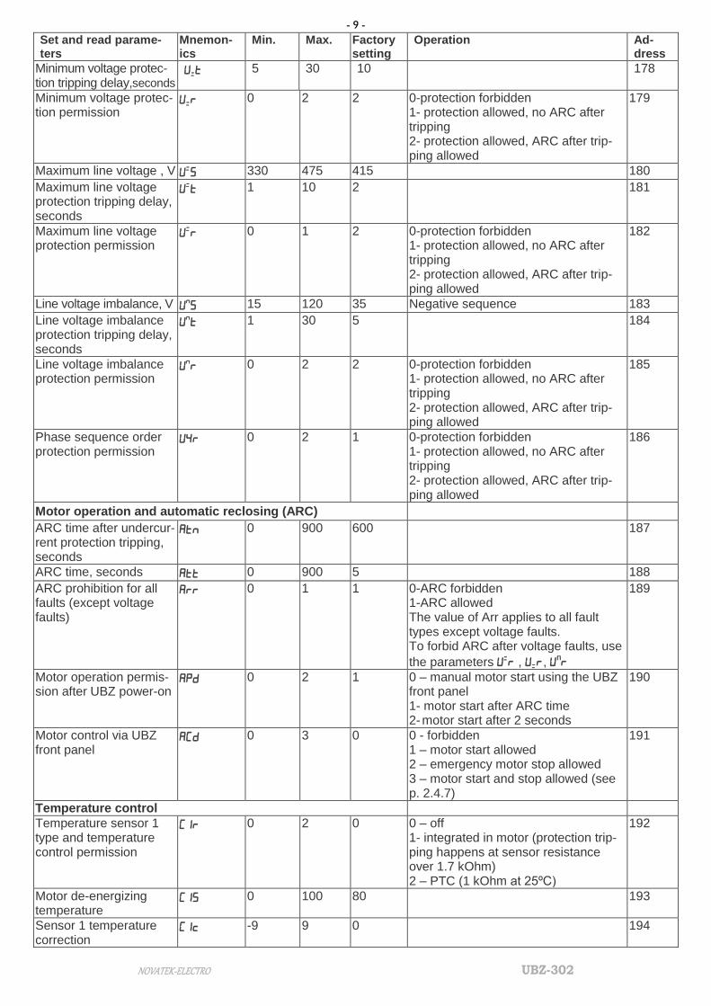
Figure 1.4 – Delayed start and rotor blocking
Delayed start. During the motor start, protection is activated when the values of all phase currents exceed the Is threshold set-
ting (the “” parameter) during a time longer than the ST time delay value (the “’ parameter). Rotor blocking After the motor start is complete (the starting current is less than 120% of the rated current), UBZ switches to
monitoring of possible rotor blocking. Protection is activated when the values of all phase currents exceed the
threshold setting during a time longer than the LT time delay value (the “” parameter).
1.2.5.7 Thermal Overload Protection Thermal overload protection is designed based on the electromotor thermal balance equation, with the following
assumptions: - the motor is cold before the first start; - during operation, the motor releases heat, in the amount proportional to the current value squared; - after the motor is stopped, it cools down exponentially.
To enable protection, set up the double overload tripping time Т2 (the “” parameter). Figure 1.5 shows the current-to-time curve for different T2 values. The current-time dependence for the standard recommended T2 value (60 sec for double overload) is shown in
Table 1.6.
Table 1.6
I/Inom 1.1 1.2 1.4 1.7 2 2.7 3
Тsec 365 247 148 88,6 60 36.4 24.6
I/Inom 4 5 6 7 8 10 15
Тsec 13.5 8.5 5.9 4,3 3.3 2.1 0.9
For rotary machines, cooling is more effective during operation than during the motor stall, which is why the
parameter is introduced – the cooling constant increase during motor stall.
After the load relay is open due to thermal overload, with automatic reclosing allowed, the relay will re-close after the bigger of the time values:
- duration of heat hysteresis (the motor should lose 33% of the accumulated heat); - ARC time.

- 16 -
UBZ-302 NOVATEK-ELECTRO
Through selection of suitable ARC times with regard to thermal hysteresis, the number of starts per time unit can be limited, because the device records the amount of heat released at the motor start when working in the in-termittent cycle.
I/Iн – current value divided by rated cur-
rent; Т/Т2 – actual tripping time divided by T2
(double load tripping time).
Figure 1.5 – Current-time curve
1.2.5.8 Coil Overheating Protection Depending on the threshold settings selected, protection can use the first input with the following temperature
sensors:
1) integrated temperature sensors (=1). In this case, the C1S setting is not involved, and neither short circuit nor sensor breakout is monitored. Protection is activated when the sensor resistance exceeds 1700 Ohm.
2) PTC type sensors (1 kOhm at 25 ºС) (this sensor should not be used to measure temperatures over 100 ºС). At the second input, protection uses temperature sensors type Pt100 (platinum, 100 Ohm at 0 ºС) or Ni100 (Ni120) (nickel, 100 Ohm (120 Ohm) at 0 ºС) corresponding to IEC 60751 and DIN 43760 standards.
Protection at the second input: - is activated when the monitored temperature exceeds the threshold setting; - has two independent threshold setting: the alarm setting and the de-energize setting. Protection detects the breakout and short circuit of temperature sensors: - breakout at temperature over 220 °C; - short circuit at temperature below minus 45 °C.
1.2.5.9 Voltage Protection In the scope of voltage protection, before the motor is energized, UBZ checks whether the voltage parameters
correspond to the user’s settings and, depending on the results, allows or forbids to energize the load. After the load is energized, UBZ continues monitoring the voltage parameters, but any de-energizing decisions are made based on current values.
Voltage protection includes: - undervoltage line protection (activated when at least one line voltage value remains below the threshold set-
ting (the “” parameter) during the time value in “”);. - overvoltage line protection (activated when at least one line voltage value remains above the threshold setting
(the “” parameter) during the time value in “
”);
- line voltage imbalance protection (activated when the difference between the RMS line voltage values ex-
ceeds the threshold setting (the “” parameter) during the time value in “
”).
1.2.5.10 Phase Sequence Protection is activated when the phase sequence order is broken; the motor is de-
energized, and its subsequent operation blocked.
1.2.5.11 Motor Coil Insulation Minimal Resistance After the device receives voltage, but before the output relay closes, UBZ checks the level of stator coil insula-
tion relative to the body. This value is also checked when the load relay is closed, but the motor currents are less than 10% of the rated current (in this case, the motor is considered to be off).
At =5 (15), the load is not energized if the coil insulation is below 500 + 20 kOhm; at =10 (20), if the coil
insulation is below 1000 + 50 kOhm. At =5 and =10, the load will be energized after the coil insulation is re-
stored and the ARC time delay has passed. At =15 and =20, no ARC takes place.
1.2.5.12 Phase Loss Protection is activated if the current at one of the motor’s phases exceeds 10% of the
rated current (“”), while in any of the other phases, the current is under 7% of the rated current.
1.2.5.13 Control of external MS working order
- 17 -
NOVATEK-ELECTRO UBZ-302
UBZ defines the engine currents presence at deactivated load relay (while load relay is deactivated and functional re-lay in mode star-delta). In this case the Unit initiates the alarm of external MS which starts the engine until the Unit is
switched off or engine currents control is switched off while the load relay is deactivated (parameter =0).
1.3 PACKAGING CONTENTS
The list of contents supplied is provided in Table 1.7.
Table 1.7 - Product Contents
Item Abbreviation
UBZ-302 device UBZ-302
Differential transformer (zero sequence transformer)
PC connection cable for RS-232* KC-01
Temperature sensor (types Pt100, Ni100 and Ni120) * Pt100, Ni100, Ni120
*Supplied as agreed with consumer
1.4 FEATURES AND OPERATION
UBZ is a microprocessor-based digital device that provides a high degree of reliability and accuracy. It requires no additional power supply, as the voltage it monitors is also used to power it.
UBZ has three integrated CTs, through which the power phase cables are led.
2 INTENDED USAGE 2.1 SAFETY
For any connections, the device must be powered off. Do not operate the unit under conditions of high humidity.
NEVER ATTEMPT TO OPERATE THE UNIT WITH THE MECHANICAL DAMAGE OF THE HOUSING. DO NOT LET WATER INTO THE UNIT
Do not use the unit in corrosive environments with the air containing acids, alkalis, oils, etc. The unit is not intended for operation under vibrations or shocks.
This unit is safe for use in case of compliance with operating rules.
2.2 DEVICE CONTROLS
2.2.1 UBZ has five control modes: - keypad lock; - mode with minimal number of setting parameters (MMSP); - user level; - engineer level; - remote control. All work modes allow: - viewing the measures and displayed parameters (table 1.4). To scroll through parameters, use DOWN and UP
buttons; - viewing the fault log (p.2.4.6). 2.2.2 When the keypad is locked, viewing and editing programmable parameters is not possible. When the keypad is locked, pressing the SETUP buttons will display the “LOC” message. To unlock the keypad,
press SETUP again. The SETUP LED will be lit, and the indicator will show a flashing “0”. Use the UP and DOWN buttons, enter the user password (consisting of numbers 1 to 9) and press the RES/MEM/SEL button. If the pass-word is correct, the keypad will be unlocked. If no button is pressed within 15 seconds of unblocking the keyboard, and the lock setting is not changed by the user, the keypad will be locked again.
NOTE – If any temperature sensor is disabled via software, the indicator will show “” instead of the temperature (resistance) value.
2.2.3 When the keypad is unlocked, it is possible to: - work in MMSP mode;
- view and edit user-level parameters; - view engineer-level parameters.
2.2.3.1 The MMSP mode is meant to simplify the use of UBZ for service personnel.
To switch the UBZ into the MMSP mode, set the value of =1 or reset to factory settings (p.2.2.4). When UBZ works in this mode, the green MMSP LED is on.
In the MMSP mode, the following parameters are sufficient for the normal operation of UBZ: - CT type (integrated or external); - rated CT current (if using external CT); - rated (operating) motor current. The difference between MMSP mode and user mode is that the parameters not included in the MMSP list are
set to default factory settings.

- 18 -
UBZ-302 NOVATEK-ELECTRO
WARNING: IF ANY PROGRAMMABLE PARAMETERS WERE EDITED BY THE USER OR THE ENGINEER, BUT NOT INCLUDED IN THE MMSP LIST, THEY WILL DEFAULT TO FACTORY SETTINGS WHEN MMSP MODE IS ACTIVATED.
Parameters not included in the list in this more are not viewed and not edited. Operations with the parameters
included in the MMSP list is the same as in the user-level mode. Adding parameters to the MMSP list and deactivating the MMSP list is only possible at the engineer level.
When the MMSP mode is deactivated (setting value of =0), the MMSP LED switches off. In the user mode, the entire parameter list is viewed. To edit a parameter:
- use the DOWN and UP buttons to select the parameter to be added; - press the DOWN and UP buttons simultaneously (the point in the higher digit of the mnemonic indicator should
disappear).
2.2.3.2 Editing and Viewing User-Level Parameters To view and edit user-level parameters, press SETUP – the SETUP LED will be illuminated. Scroll through the
parameters using the DOWN and UP buttons; press SETUP to enter parameter editing mode (the parameter value will start flashing); edit the parameter value using the DOWN and UP buttons; press RES/MEM/SEL to save the pa-rameter value, SETUP to return to the menu without saving, and RES/MEM/SEL to leave the menu. If no button is pressed during 30 seconds, UBZ returns to the initial state.
2.2.3.3 Editing and Viewing Engineer-Level Parameters Entering engineer mode Press the SETUP button and keep pressed for 5 seconds. If engineer mode is password-protected, the indicator
will display the “PAS” message. The SETUP LED will be illuminated, and the parameter value indicator will flash “000”. Use UP and DOWN to enter the engineer’s password (three digits from 1 to 9), pressing RES/MEM/SEL after each digit. If the password is wrong, the “PAS” message will be displayed, flashing in the higher digit; 15 seconds later, UBZ will return to the initial state. If the password is correct, the first engineer menu parameter will be dis-played.
To scroll through the parameters, use DOWN and UP; press SETUP to enter parameter editing mode (the pa-rameter value will start flashing); edit the parameter value using the DOWN and UP buttons; press RES/MEM/SEL to save the parameter value, SETUP to return to the menu without saving, and RES/MEM/SEL to leave the menu. If no button is pressed during 30 seconds, UBZ returns to the initial state.
When UBZ is used in engineer mode, the decimal point is displayed in the lower digit of the mnemonic indicator. At the engineer level, access to any user-level parameter can be granted or denied by pressing SETUP and
DOWN simultaneously. Denied access is indicated by the decimal point displayed in the middle digit of the mne-monic indicator.
At the engineer level, any parameter can be added to the MMSP parameter list. To do that: - use DOWN and UP to select the parameter to be added; - press DOWN and UP simultaneously (the decimal point in the higher digit of the mnemonic indicator should
disappear). To remove a parameter from the MMSP parameter list: - use DOWN and UP to select the parameter to be removed; - press DOWN and UP simultaneously. If the parameter is excluded from the MMSP list, the decimal point will be displayed in the higher digit of the
mnemonic indicator.
2.2.4 Reset to Factory Settings There are two ways of resetting UBZ to default factory settings.
Method one. Set the value of =1. After leaving the parameter setting mode, all factory settings will be reset (except for the engineer password).
Method two. When UBZ is being powered on, press the buttons SETUP and RES/MEM/SEL and keep them pressed for two seconds. All factory settings will be reset, including the engineer password (engineer password set to 123).
After resetting to the default factory parameters, UBZ will work in the MMSP mode, with the following list of pa-rameters:
- CT type (external or integrated), ;
- rated CT current (for external CT), ;
- rated motor current, .
2.2.5 UBZ ALARMS RESET on the front panel The Alarms Reset is to be carried out while the engine is switched off. For carrying out the Alarms Reset on the
front panel it is necessary to press simultaneously the buttons RESET and DOWN, thereat: - the alarms are being reset no matter whether the APV is disabled or enabled (except for the current alarms
on engine currents availability at the load relay being deactivated ); - counting of APV ends;

- 19 -
NOVATEK-ELECTRO UBZ-302
- if there are no new alarms, the engine starts. 2.3 PREPARING UBZ FOR OPERATION WARNING: TO IMPROVE THE OPERATING QUALITY OF UBZ, IT IS RECOMMENDED TO INSTALL FUSES
(THERMAL OR EQUIVALENT) IN THE FOLLOWING CIRCUITS (LISTED IN THE ORDER OF IMPORTANCE, WITH RECOMMENDED FUSE RATING):
1) relay output terminals (the specific rating value of the fuses is determined according to the working line but should not exceed for terminals 1, 2, 3 – 15 А, and for terminals 4-9 – 5 А);
2) power supply lines of UBZ (27,28, 30, 31 - L1,L2,L3, N) -1 A; 3) engine isolation measuring lines (25, 26 - R-iz, R-iz_N) - 0,5 А. 2.3.1 For electric motors of 2.5 kW to 30 kW capacity, integrated current transformers can be used. The wires to
the motor should be led through the openings in the UBZ housing (each phase wire through a separate opening). For motors of other capacity, connect current transformers with 5A rated output current, as shown in Figure 2.1. 2.3.2 Conduct all three phase wires through the differential current transformer (zero sequence transformer) and
connect it to the UBZ. 2.3.3 To monitor and measure the motor insulation, connect the insulation monitoring terminal 25 to one of the
MS (magnetic starter) outputs. If the motor housing is not grounded, a circuit with isolated neutral is in use, or no neutral wire is connected to the UBZ terminal – connect the motor housing to terminal 26 electrically.
2.3.4 Connect UBZ to the electric circuit as shown in Figure 2.1. If using a motor with star-delta coil switching, connect as described in Appendix 2.
2.3.5 To operate UBZ via a personal computer using the UBZ-302 Control Panel software: - install the UBZ Control Panel software on the PC by running setup_cplubz302(Standart)(x.x).exe, where x.x.
is the software version; - connect the RS-232 socket on the UZB front panel to the RS-232 socket of the PC using the KC-01 cable;
- set the value of “=1”.
NOTE:
1 The file setup_cplubz302(Standart)(x.x).exe can be downloaded from the website of NOVATEC-ELECTRO (http://novatek-electro.com/en/software.html).
2 The КС-01 cable is supplied to order. It can also be made by the user as shown in Figure 2.2. 3 User-developed software can also be used to operate UBZ.
2.3.6 If using the MODBUS protocol, connect the communication lines to the UBZ terminals 33 (GND), 34 (RS-
485 B line), 35 (RS-485 A line). Set the value of “=2”. 2.3.7 Power UBZ on.
The procedure for the load relay closing is determined by the values of and (p. 2.4.1.).
WARNING: UBZ IS SUPPLIED WITH THE MOTOR RATED CURRENT SET TO ZERO. IN THIS CASE, THE UBZ LOAD RELAY WILL NOT BE ON BEFORE THE MOTOR RATED CURRENT VALUE IS SET. THE MOTOR RATED CURRENT MUST BE AT LEAST 5A.
2.3.8 Set the necessary parameter values in the menu. 2.3.9 Power UBZ off. 2.3.10 Connect the magnetic starter (MS) as shown in Figure 2.1.
NOTE: when the load relay is on, contacts 5-6 and 8-9 are closed, when it is off, the contacts 4-5 and 7-8 are closed.
2.4 INTENDED USAGE
NOTE – Descriptions of the UBZ operation assume that the appropriate protection types are activated and all neces-sary sensors are connected.
2.4.1 UBZ Operation Before Load Relay Activation 2.4.1.1 UBZ Operation After Power On (First Use)
After the device is powered on, the mnemonic indicator displays "" for 1-2 seconds. Then, before activating the load relay, UBZ checks:
- the level of stator coil insulation relative to the body (if the insulation resistance is under 500 + 20 kOhm at
=5 (1,000 + 50 kOhm at =10), the load is not energized); - quality of voltage: phase completion, symmetry, RMS line voltage value; - correct phase order, lack of phase coincidence. In case any prohibiting factor is present, the load relay is not activated, the mnemonic indicator displays the ap-
propriate fault code, and the FAULT LED is illuminated.
Depending on the value of , the indicator displays:
- linear voltage Uab at =0;
- insulation resistance (rid) at =1;
- ARC countdown in seconds (Att) at =2.

- 20 -
UBZ-302 NOVATEK-ELECTRO
If no forbidding factors are present, activation of the load relay is determined by the value of (UBZ opera-tion after power-on).
Relay K1 – load relay Relay K2 – functional relay
Figure 2.1 – UBZ wiring chart
1) At =0, the load relay will not be activated. At this setting, press UP and DOWN simultaneously to
activate the load relay.
2) At =1, the load relay will be activated after ARC delay time.
3) At =2, the load relay will be activated 2 seconds after power-on. At the same time as the load relay is activated, the green LOAD LED is illuminated. After the relay activation and
before the motor start (the motor start is determined as the load current exceeding 120% of rated current), the voltage quality continues to be monitored, with appropriate decision-making. If any forbidding factors arose during the dead time, the load relay will be deactivated.
P. 2.4.4.8 describes UBZ operation when remote motor control is allowed via the RS-232/RS-485 (=1,
=2) interface. 2.4.1.2 UBZ Operation After De-Energizing After Fault In this case, UBZ operates as during first power-on, but activation of the load relay does not depend on the val-
ue of .
If ACR after fault is not allowed (=0), the motor cannot be energized before UBZ is powered off. The value of
applies to all types of faults, except voltage faults. To forbid ARC after voltage faults, use the parameters , ,
.
2.4.2 UBZ Operation After Load Relay Activation and Motor Energizing (currents of over 10% of the motor rated current).
UBZ carries out voltage and current control. The load relay is deactivated when any protection type mentioned in Table 2.8 is tripped, except:
- voltage protection;
- overcurrent protection at =1 (in this case, overcurrent is indicated, but the load relay is not deactivated).

- 21 -
NOVATEK-ELECTRO UBZ-302
The indicator can display the motor phase A current or the value of the user-selected parameter. The value of
the user-selected parameter can be displayed constantly (=0) or during 15 seconds, after which the indicator
resumes displaying the motor phase A current (=1). 2.4.3 Functional Relay Operation
The functions carried out by the functional relay are determined by the value of .
At =0, the relay is used as a signaling relay (the (S/D) and TR LEDs are not illuminated). The relay contacts are closed in case of any of the faults listed in Table 2.8.
At = 1, the relay is used as a time relay (the S/D and TR LEDs are illuminated). The relay is activated after a
time specified in “”, after the load relay is activated.
At = 2, the relay is used to switch the motor coils from star to triangle (the З/Т (S/D) LED is illuminated). In
this mode, the load relay is activated the same as at =0, but after the time specified in “”, it is deactivated.
Then, after a time specified in “” passes after the deactivation of the load relay, the functional relay is activated.
NOTE – When the functional relay is activated, the contacts 1-2 are open, and the contacts 2-3 are closed.
2.4.4 Using the RS-232/RS-485 Interface with the MODBUS Protocol, RTU Mode UBZ allows exchanging data with an external device using the serial interface and the MODBUS protocol. Dur-
ing data exchange via RS-485 or RS-232, the blue EXCHANGE LED is illuminated. 2.4.4.1 Communication Parameters:
- device address: 1-247 (parameter );
- data transfer rate: 9,600 baud, 19,200 baud (parameter ); - reaction to loss of link: warning with continued operation; warning with motor stopping; continued operation
with no warning (parameter );
- timeout detection: 1 –120 seconds (parameter ); - word format – 8 bit, no parity check, two stop bits.
2.4.4.2 UBZ Operation via PC A PC is connected to the UBZ via a serial interface. The connection scheme is shown in Figure 2.2. Each UBZ
has a unique communication address that is used by the PC to distinguish between different UBZs. UBZ can work in Modbus networks using the RTU mode.
3 RxD
GND
1
UBZ-302 X2
Cont
8
X1
X2
X1
Computer
2
Plug for connecting of the handset PLUG-4P4C-P-C2
"RS-232" Cont
4
Socket DB-9
com-port
9
1
5
Designat
ion
Designat
ion
6
TxD 2
3
TxD
7
RxD
4 SG
Figure 2.2 – Connecting UBZ to a PC
2.4.4.3 Communication Protocol Data exchange between a PC and the UBZ is done in packets. The data packet format is described in Table 2.1.
Table 2.1
START silence interval – over 4 ms at 9,600, or over 2 ms at 19,200 baud
ADR UBZ communication address (8 bits)
CMD Command code (8 bits)
DATA 0 Data contents: N*8 data bits (n<=24) ….

- 22 -
UBZ-302 NOVATEK-ELECTRO
DATA (n-1)
CRC CHK low CRC checksum 16 bits CRC CHK high
END silence interval – over 4 ms at 9,600 baud, or over 2 ms at 19,200 baud
2.4.4.4 MODBUS interface commands (CMD (Command Code) and DATA (Data Characters)) The format of data character depends on command codes. Command code 0x03, reading n words. For example, reading 2 words continuously starting from the address 64H in the UBZ with communication ad-
dress 01H (Table 2.2). NOTE – while performing one command there could be read not more than 12 registers (n=12).
Command code 0x06, writing one word Using this command is not recommended, because writing incorrect data may result in UBZ failure. Data can only be written using the addresses of programmable parameters (see Table 1.5), except the parame-
ters listed in Table 2.3.
Table 2.2
Command Message Feedback Message
ADR 0x01 ADR 0x01
CMD 0x03 CMD 0x03
Data start address 0x00 0x64
Data amount, bytes 0x04
Data amount, words 0x00 0x02
Data contents at address 0x17 0x70
CRC CHK low 0x85 Data contents at address 0x00 0x00
CRC CHK high 0xD4 CRC CHK low 0xFE
CRC CHK high 0x5C
Table 2.3
Set and Read Parameters Code Parameters Address
Total device uptime, days 207
Motor uptime, days 208
User access code 209
Engineer access code 210
Reset to factory parameters 211
Device version 217
The parameter is written regardless of any engineer protection set (writing via the communication line has a higher priority).
When a new value is written into a MMSP-protected cell, the parameter is automatically excluded from the MMSP mode.
The parameters being written must be a multiple of the interval specified in Table 1.5. For example, Table 2.4 shows the procedure of writing the entry 1000 (0x03E8) into the register at the address
0x00A0, in the UBZ with the communication address 01H.
Table 2.4
Command Message Feedback Message
ADR 0x01 ADR 0x01
CMD 0x06 CMD 0x06
Data start address 0x00 0xA0
Data start address 0x00 0xA0
Data 0x03 0xE8
Data 0x03 0xE8
CRC CHK low 0x89 CRC CHK low 0x89
CRC CHK high 0x56 CRC CHK high 0x56
Command code 08h – diagnostics. The 08h function provides for a number of tests used to check the communication between the PC and the
UBZ, and to check the UBZ operational state. The function uses the sub-function field to elaborate the action (test). Sub-function 00h – return query data. The data sent in the data field of the query must be returned in the data field of the response.

- 23 -
NOVATEK-ELECTRO UBZ-302
Figure 2.3 shows an example of a query and a response.
Figure 2.3 – Example of query and response of the sub-function 00h – return query data
Sub-function 01h – restart communication options. While performing the command only the change of communication speed is carried out in UBZ. For total change of
communication parameters it is necessary to initiate the command "UBZ RESTART" ("RESTART") (item 2.4.4.10). Figure 2.4 shows an example of query and response.
Figure 2.4 – Example of query and response of the sub-function 01h – restart communication options.
2.4.4.5 CRC – Cyclic Redundancy Check The checksum (CRC16) is a cyclical checking code based on the A001h polynomial. The transmitter creates a
checksum for all bytes of the transmitted message. The receiver creates the checksum for all bytes of the received message and compares it to the checksum received from the transmitted. If the created and received checksums are not the same, an error message is generated.
The checksum field occupies two bytes. In a message, the checksum is transmitted least significant byte first. The following algorithm is used to create the checksum: 1) load CRC register (16 bite) with ones (FFFFh); 2) XOR gate with the first 8 bits of the message byte and the contents of the CRC register; 3) shift result one bit to the right; 4) if the shifted bit = 1, XOR gate with the register contents with value of A001h; 5) if the shifted bit = 0, repeat step 3; 6) repeat steps 3, 4, 5, until 8 shifts are carried out; 7) XOR gate with the next 8 bits of the message byte and the contents of the CRC register; 8) repeat steps 3-7 until all bytes of the message are processed; 9) the final contents of the register will contain the checksum. An example of CRC generating code on C. The function receives two arguments:
- Unsigned char* data <- indicator to message buffer; - Unsigned char length <- number of bytes in the buffer.
The function returns the CRC value as (unsigned int). Unsigned int crc_chk(unsigned char* data, unsigned char length)
{int j; unsigned int reg_crc=0xFFFF; while(length--) { reg_crc ^= *data++; for(j=0;j<8;j++) { if(reg_crc & 0х01) reg_crc=(reg_crc>>1) ^ 0xA001; // LSB(b0)=1 else reg_crc=reg_crc>>1; } } return reg_crc; }
2.4.4.6 Register Addresses Table 1.4 shows the register addresses of measured and calculated UBZ parameters. Table 1.5 shows the reg-
ister addresses of programmable parameters. Table 2.5 shows additional registers and their purpose.

- 24 -
UBZ-302 NOVATEK-ELECTRO
Table 2.5
Name Address Purpose
register 240
Bit 0 0-no fault 1-fault (fault code in register 241)
Bit 1 0 – load relay open 1 – load relay closed
Bit 2 0– functional relay open 1 – functional relay closed
Bit 3 0 – no restart 1 – ARC expected
Bit 5-4 Functional relay operating mode 00 – signaling relay 01 – time relay
10 – star / delta
Bit 6 0 – MSM mode off 1 – MSM mode on
Bit 7 0 – regular operating mode 1 – UBZ in hysteresis area when working with analog outputs
Fault register 1 241 bit mapping according to Table 2.8
Fault register 2 242 bit mapping according to Table 2.8
Fault log
Alarm code N 243+(N-1)*4 fault code according to Table 2.8
Parameter value N 223+(N-1)*4+1 parameter value according to Table 2.8
Alarm time N 243+(N-1)*4+2 two upper bytes
243+(N-1)*4+3 two lower bytes NOTE:
1 Alarm time is a time period spent from the moment of initiation of power supply to UBZ till the moment of alarm taking place. It is measured in minutes.
2 While the UBZ sale and delivery or after the factory settings (п.2.2.4) the alarm code 40 and parameter value 10000 is written in the alarm register book.
3 While initiation of power supply to UBZ the number 5000000 is written in all alarm time registers. 4 N – alarm number. It can be from 1 to 5.
2.4.4.7 Communication Error Processing In case of an error during frame reception (parity error, frame error, checksum error), UBZ returns no response. In case of an error in format or value of transmitted data (unsupported function code, etc.), UBZ accepts the
query frame and creates a response containing the error indication code. The error indication is the 1 in the higher bit of the function field. A separate field is reserved for the error code in the response. Figure 2.5 shows an example of a response.
Table 2.6 provides error codes.
Figure 2.5 – Example of a response after error
Table 2.6
Error code
Name Description
01h ILLEGAL FUNCTION The UBZ cannot process the accepted function code
02h ILLEGAL DATA ADDRESS
The data address in the query is not accessible by this slave device
03h ILLEGAL DATA VALUE The value in the query data field is not acceptable for the UBZ
04h SLAVE DEVICE FAILURE An unrecoverable error occurred when UBZ tried to carry out the re-quested action

- 25 -
NOVATEK-ELECTRO UBZ-302
05h ACKNOWLEDGE The UBZ accepted the query, but processing it requires a long time. This response prevents the master device from generating a timeout error
06h SLAVE DEVICE BUSY The UBZ is busy processing the command. The master device should resent the message later, when the slave device is free
07h NEGATIVE ACKNOWLEDGE
The UBZ cannot carry out the program function contained in the query
2.4.4.8 Remote Motor Control Using the RS-232/RS-485 Interface
Remote control of the UBZ is determined by the value of .
At =0, remote control of the motor is forbidden.
At =1, the UBZ operation after energizing is the same as with remote control off (regular operation), but writ-ing into the R_COMMAND command register is allowed.
At =2, the UBZ will energize the motor only after a respective command is received via the RS-232/RS-485 interface.
The value of R_COMMAND is taken into consideration by the UBZ operation algorithm at =1 and =2. If
=0, and the user sets =1 or =2, “0” will be written to R_COMMAND. Table 2.7 shows a list of the possible settings of the command register.
At =1, “1” will be written into the command register after power on (regular operation). At =2, “0” will be written into the command register after power on (the motor is switched off until the energize command is given).
After emergency de-energizing of the motor by simultaneous pressing of UP and DOWN (at =2 or =3), the command register will be reset to 0.
Table 2.7
Command register R_COMMAND Address = 237
Actions
0 De-energize motor. If the motor is off, it will not be energized until a remote energize com-mand is given. If the motor is on, it will be de-energized.
1 Regular device operation. If the motor was de-energized by a remote command, or by simultaneous pressing of ВВЕРХ / UP and ВНИЗ / DOWN (at ACd=3), or by a fault with permitted subsequent ARC, then after 1 is written into R_COMMAND, the motor will be energized after the ARC time delay.
2 Early motor de-energizing. Writing 2 into R_COMMAND results in the motor energizing be-fore the end of the ARC time delay. After the motor is on, R_COMMAND = 1.
55 (37 Hex) Command "UBZ ALARMS RESET" (item 2.4.4.9)
88 (58 Hex) Command "UBZ RESTART" ("RESTART") (item 2.4.4.10)
2.4.4.9 Command "UBZ ALARMS RESET" The command "UBZ ALARMS RESET" is to be initiated after entering the command code 55 in command reg-
ister (table 2.7) by interface RS-232/RS-485. While initiating the command: - the alarms are being reset no matter whether the APV is disabled or enabled (except for the current alarms on
engine currents availability at the load relay being deactivated and alarm of EEPROM destruction); - ahead of time counting of APV ends and, if there are no new alarms, the engine starts.
2.4.4.10 The command "UBZ RESTART" ("RESTART") The command "UBZ RESTART" is used for initiating the changed communication parameters. The command
"UBZ RESTART" is to be initiated after entering the command code 88 in command register (table 2.7) by interface RS-232/RS-485. After receiving the command "UBZ RESTART" UBZ does not return the confirmation of received command.
NOTE: Between the last addressing to registers UBZ-302 and entering the command "UBZ RESTART" there should be a time delay not less than 100 msec.
ATTENTION! IT IS FORBIDDEN TO INITIATE THE COMMAND "UBZ RESTART" ("RESTART") WITH ENGINE BEING IN OPERATION.
2.4.4.11 Resetting of the UBZ factory settings via MODBUS interface.
For initiation of this operation it is necessary to set the parameter =1. At this operation the parameters of se-rial interface will not be changed (the reset of interface parameters to the factory ones is not made). The time period
of reset to the factory settings is up to 5 seconds. After the completion of operation the parameter is =0. ATTENTION! IT IS FORBIDDEN TO MAKE A RESET TO THE FACTORY SETTINGS VIA MODBUS INTERFACE WITH ENGINE BEING IN OPERATION.

- 26 -
UBZ-302 NOVATEK-ELECTRO
IT IS FORBIDDEN TO ENTER THE PARAMETERS VIA MODBUS INTERFACE UNTIL THE COMPLETION OF RESET OPERATION.
2.4.5 Fault Status System In case of a fault status: - the mnemonic indicator displays a fault code as per Table 2.8; - the value indicator displays the value of the parameter to which the fault is related (if the fault status has no
numerical value, the indicator displays “---“) ; - the red FAULT LED is illuminated (steady glow if no ARC is allowed, or blinding if ARC is expected); - the load relay opens;
- the functional relay closes (at =0). If UBZ detects several types of faults simultaneously, fault codes and their parameter values are displayed se-
quentially. If ARC is allowed, the indicator displays fault codes and the time to ARC (if the time delay for thermal overload
exceeds the ARC delay time, the former is displayed).
Table 2.8 - Fault Codes
Fault name Fault mnemonic
Parameter value Parameter value register address
Fault code
N bit regis-ter address
phase overcurrent maximum phase volt-
age 300 0 241:0
thermal overload 301 1 241:1
ground fault (zero sequence current) zero sequence current 302 2 241:2
exceeded value of negative sequence current ratio divided by negative se-quence voltage ratio
negative sequence cur-rent ratio * 100
303 3 241:3
negative sequence current negative sequence cur-rent
304 4 241:4
phase undercurrent 305 5 241:5
delayed start current 306 6 241:6
rotor blocking current 307 7 241:7
temperature threshold at sensor 1 temperature, degrees 308 8 241:8
temperature threshold at sensor 2 temperature, degrees 309 9 241:9
phase sequence 310 10 241:10
External MS (by presence of currents with a load relay being disabled)
current 311 11 241:11
line undervoltage voltage 312 12 241:12
line overvoltage voltage 313 13 241:13
phase imbalance imbalance 314 14 241:14
motor coil insulation resistance insulation resistance 315 15 241:15
remote control channel fault 16 242:0
emergency motor stop without ARC 17 242:1
emergency motor stop with ARC, by simultaneous pressing of ВВЕРХ / UP and ВНИЗ /DOWN
18 242:2
short circuit of temperature sensor 1 19 242:3
breakout of temperature sensor 1 20 242:4
short circuit of temperature sensor 2 21 242:5
breakout of temperature sensor 2 22 242:6
phase loss 23 242:7
EEPROM destruction 24 242:8
0-20 mА analog input 325 25 242:9
0-10 V analog input 326 26 242:10

- 27 -
NOVATEK-ELECTRO UBZ-302
WARNING: The "" fault (EEPROM destruction) means that the programmable parameter data (see Table 1.5) are damaged. To continue operation, power down UBZ and reset to factory settings (see p. 2.2.2 – method two).
2.4.6 Fault Status Log When the load relay is deactivated in case of a fault, the UBZ stores the fault code, the value of the parameter
that caused the fault, and the time of the fault (the time passed between the UBZ power on and the fault). The maximum number of fault codes stored simultaneously is five. After subsequent faults, information about
the fault is overwrites the oldest entry. To view the log, press RES/MEM/SEL. The SETUP LED will be illuminated (flashing), and the UBZ indicators will display the first row from Table 2.9.
To scroll through the log, use UP and DOWN. Table 2.9
Displayed on mnemonic indicator Displayed on value indicator
“Adi” number of log entry (1 is the newest)
XXX – fault mnemonic accord-ing to Table 2.8
YYY – parameter value as per Table 2.8 (if no parameter value, indicator displays “---“)
XXX – hours since fault YY – minutes since fault
To leave the log, press RES/MEM/SEL. Otherwise, the log will be closed automatically, 30 seconds after any
button was pressed. Information about the fault is displayed on the UBZ indicators in the format shown in Table 2.9. When UBZ is powered on, 5000000 is written into the registers used to store fault time. In this case, the mne-
monic indicator and the value indicator display "---" and " –", respectively.
2.4.7 Controlling the Motor Using the UBZ Front Panel
Depending on the value of , the UBZ load relay can be controlled using the buttons UP and DOWN (unless the
keypad is locked):
=0 – no reaction;
=1 (motor start allowed) – the load relay will close unless the ARC time has expired;
=2 (emergency motor stop) – the load relay will open, with fault code “”. Motor restart is only possible af-
ter powering the UBZ off and on again;
=3 (motor start and stop permitted) – the load relay opens, with fault code “”. To energize, press the but-
tons UP and DOWN.
NOTE – When the values are set to “=0” (manual motor start from the UBZ front panel after power on) and
“=0” (manual motor control forbidden), the load relay will not be activated.
WARNING: IF REMOTE CONTROL IS ALLOWED ("=1"), MOTOR START FROM THE FRONT PANEL IS FORBIDDEN.
2.4.8 Controlling the Motor Using the Analog Inputs Algorithms for controlling the motor using the analog inputs 0-20 mA and 0-10 V are provided in Table 1.5. After motor de-energizing through a fault value, ARC countdown will only start after the parameter value leaves
the fault range. If, after motor de-energizing through a fault value, the value remains between the motor energizing and de-
energizing levels (the FAULT indicator is not illuminated, but the mnemonic indicator displays the fault code), early motor start is possible, using the front panel buttons or remote control.
3 TECHNICAL MAINTENANCE 3.1 SAFETY PRECAUTIONS
REPAIR, MAINTENANCE AND ASSEMBLY WITHOUT DISCONNECTING THE DEVICE FROM THE CIRCUIT IS FORBIDDEN. NEVER ATTEMPT TO REMOVE AND REPAIR THE UNIT. Some of the unit components may be live.
NEVER ATTEMPT TO OPEN AND REPAIR THE PROTECTED EQUIPMENT, IF SWITCHED TO THE UNIT SOCKET.
Do not use abrasives or organic compounds for cleaning (spirit, gasoline, solvents, etc.). Installation, adjustment and maintenance of the unit should only be provided by the qualified personnel, having
reviewed this Operating manual
- 28 -
UBZ-302 NOVATEK-ELECTRO
3.2 TECHNICAL MAINTENANCE PROCEDURE
Technical maintenance is recommended to make every 6 months Technical maintenance entails a visual examination, including checking that the wires are properly connected to
the UBZ terminals, and the housing is free of cracks and chips.
4. TRANSPORTATION AND STORAGE UBZ-302 in the manufacturers package should be carefully stored in dry places with ambient temperature from
-50 to +60 C and relative air humidity not more than 80%. Air should not contain any chemically aggressive va-pors. When transporting customer should provide suitable packing that would protect the UBZ-302 from any me-chanical damages, serious drops and vibrations that may affect the device integrity.
5. TERMS OF SERVICE AND MANUFACTURER’S WARRANTY The service life of UBZ-302 is 10 years. After the service life is over, one should contact the manufacturer.
Warranty period is 36 month upon the day of sale. The manufacturer shall repair the unit, in the compliance with the operating manual by the user, within the warran-
ty period. UBZ-302 is not subject to the warranty service in the following cases: expiry of the warranty period;
availability of mechanical damages; attempts to open and repair; traces of moisture attack or in the presence of foreign items inside the unit:
damage is caused by electric current or voltage in excess to the permissible values as indicated in the Operating manual
Warranty service is provided in the place of purchase Post-warranty service shall be provided by the manufacturer. The manufacturer's warranty does not cover compensation for direct or indirect losses associated with the unit
transportation to the place of purchase or manufacturer’s plant.

- 29 -
NOVATEK-ELECTRO UBZ-302
APPENDIX 1. Current protections with different time-dependent delay

- 30 -
UBZ-302 NOVATEK-ELECTRO

- 31 -
NOVATEK-ELECTRO UBZ-302
APPENDIX 2 – UBZ-302 operation by the motor in the star/delta switching mode
If before the start of the motor it is not necessary to test and check the insulation of the coils to the case of the motor then it’s allowed to connect the UBZ-302 according to the simplified scheme shown on Figure P1 below.
If before the start of the motor it’s necessary to test the insulation level of the coils to the motor case then the connection must necessarily be done as shown on Figure P2.
When working in the delta/star switching mode the motor could be controlled in a several ways: - Turn OFF/ON of the motor by external circuit breaker (contactor) with simultaneous power supply OFF/ON to
the input terminals of the UBZ-302; - Operation with the motor from the front panel of the UBZ-302; - Operation with the motor using interface RS-232/RS-485. ATTENTION!!! It is strictly prohibited to turn OFF the motor by external circuit breaker (contactor) without taking
OFF the power supply from the input terminals of the UBZ-302. As a very exception it’s possible to disconnect first the motor by external breaker (contactor) and then additionally turn the motor OFF from the front panel of the UBZ-302 or alternatively by giving the corresponding remote control command by interface RS-232/RS-485 to avoid the direct start on Delta.
К1 – contactor to turn ON the coils for Delta scheme К2- contactor to turn ON the coils for Star scheme
Figure P1 - Wiring diagram for the UBZ-302 for star/delta mode of operation without the control of the coils insulation
K2-nc
T2b
2
L1
V2
25
40
K1-2-com
W2
K1-2-nc
51
N
AN_I
temp_dat2-1
B RS-485
L1
b
t
X2
T3e
17 c
14
50
T1
5
35
temp_dat2-2
39
d
R_iz
24
T1e
52
30
1
e
K1-1-no
9
N K1-1-nc
48
49
GND
L3
GND
f
T2
33
Tdif_e
16
R_iz_N
T3b
X1-2
b
X1-1
GND
AN_U
19
23
K2-no
GND_RS232
c
R1 Pt100
4
K1-1
26
L3
8
GND
d 45
K1-1 TxD_rs232
K2-1
K1-1-com
Tdif_b
K1-2-no
3
e
4
7 34
3
28
UBZ-302
A RS-485
K1
f
T1b
K2-com
R2 PTC
T2e
K1-2
U1
44
T4
M
L2
T3
U2
a
GND
K2
RxD_rs232
K2
temp_dat1
V1
15
2
6
31
W1
t
18
27
L2
a

- 32 -
UBZ-302 NOVATEK-ELECTRO
W1
34
U1
K5
9
M
W2
K2-nc
T3b
X1-1
K5-1
V2
RxD_rs232
L3
V1
3
L1
X2
R2 PTC
A RS-485
b
2 TxD_rs232
31
e
33
30
UBZ-302
K1-2 K1-2-com
f
K2-no N
.
52 51
K1-1
L1
23
K2-2
7
1
U2
8
K1-1-no
17
K2-1
temp_dat2-1
T3e
K3-1
4
R_iz_N
5 K1-1-nc
т
T1e
48
T1
GND
15
temp_dat2-2
16 T2
B RS-485
R_iz
3
b
c
T4 t
K1-2-nc
GND
d
R1
Pt100
K1-1-com
e
GND rs232
44
T2e 45
a
40
24
L2
25 Tdif_e temp_dat1
K2-com
GND
18
35 K1-2
Tdif_b
2
T2b
L2
50
AN_U 14
N
39
K4
0
K2
6
K1
-1
f
28
49
K3
T1b
4
c
K4-1
GND
K1
t
AN_I
K2
T3
L3
26
19
K1-2-no
a
GND
d
27
X1-2
К1- intermediate relay to turn the coils for Delta К2 – intermediate relay to turn the coils for Star К3- main contactor for starting the motor К4 – contactor to turn the coils for Delta К5 – contactor to turn the coils for Star
Figure P2 - UBZ-302 Wiring diagram for the Star-Delta operation mode and the control of the coils insulation level