DESIGN AND ONSTRUTION OF ...
15
GSJ: Volume 7, Issue 9, September 2019, Online: ISSN 2320-9186 www.globalscientificjournal.com DESIGN AND CONSTRUCTION OF HYBRID ARC WELDING MACHINE 1 Man Alhaji Sulaiman, 2 Makinde Kayode, 3 Abdullahi Abubakar Yanda, 4 Lawal Olawale Kazeem, and 5 Amao Enock 1,2,3,4 Department Of Electrical Engineering, Federal Polytechnic Bida, Niger State. 5 Department of Physics, Federal Polytechnic Bida, Niger State Nigeria ABSTRACT Hybrid arc welding machine is designed to serve with an input current ranging from 40- 50Amps from AC power supply mains and 100AH 24VDC battery. The primary side through which voltage is supplied to the machine has 220 turns which is made of 2.38mm with equivalent standard wire gauge of 13 copper coils. The secondary side is connected to a rectifier with 24 turn made of 3.09mm with equivalent standard wire gauge of 8 copper coil. Both turns are wound on a limb of the laminated core. The voltage from primary turns flow to the secondary turns by induction. The welding current is adjusted when the variable resistor knob is rotated clockwise; the magnetic flux leakage and the inductive impedance are brought down causing the welding current to rise. Also at DC batteries power supply, an inverter circuit was designed. The inverter is connected with an oscillator to provide a frequency of 50Hz for the machine used in welding. The materials and equipments use include copper wire, bending machine, pliers, filling machine, screwdriver, soldering iron, lead sucker, tester and multi-meter. The locally constructed hybrid arc welding machine is capable of producing 20Amps arcing current during welding both on AC and DC source with 220V and 24VDC 200AH batteries respectively. At the end of this construction, there were no challenges observed in the power quality problems and the leakage of the welding transformer. This is because this paper focuses on the design and construction of a dual source arc welding machine putting into consideration quality laminating sheets as well as its thickness. This constant current supply desired to solve the power quality problems. At the end of this construction, it shows that the higher the turns, the more efficient the transformer and more the arcing produced. These attributes shows huge success. Keywords: Dc source, Ac source, Primary coil, Secondary coil, Current, Welding, Oscillator circuit GSJ: Volume 7, Issue 9, September 2019 ISSN 2320-9186 1217 GSJ© 2019 www.globalscientificjournal.com
Transcript of DESIGN AND ONSTRUTION OF ...

GSJ: Volume 7, Issue 9, September 2019, Online: ISSN 2320-9186 www.globalscientificjournal.com
DESIGN AND CONSTRUCTION OF HYBRID ARC
WELDING MACHINE
1Man Alhaji Sulaiman,
2Makinde Kayode,
3Abdullahi Abubakar Yanda,
4Lawal
Olawale Kazeem, and 5Amao Enock
1,2,3,4
Department Of Electrical Engineering, Federal Polytechnic Bida, Niger State. 5Department of Physics, Federal Polytechnic Bida, Niger State Nigeria
ABSTRACT
Hybrid arc welding machine is designed to serve with an input current ranging from 40-
50Amps from AC power supply mains and 100AH 24VDC battery. The primary side through
which voltage is supplied to the machine has 220 turns which is made of 2.38mm with
equivalent standard wire gauge of 13 copper coils. The secondary side is connected to a
rectifier with 24 turn made of 3.09mm with equivalent standard wire gauge of 8 copper coil.
Both turns are wound on a limb of the laminated core. The voltage from primary turns flow to
the secondary turns by induction. The welding current is adjusted when the variable resistor
knob is rotated clockwise; the magnetic flux leakage and the inductive impedance are brought
down causing the welding current to rise. Also at DC batteries power supply, an inverter
circuit was designed. The inverter is connected with an oscillator to provide a frequency of
50Hz for the machine used in welding. The materials and equipments use include copper
wire, bending machine, pliers, filling machine, screwdriver, soldering iron, lead sucker, tester
and multi-meter. The locally constructed hybrid arc welding machine is capable of producing
20Amps arcing current during welding both on AC and DC source with 220V and 24VDC
200AH batteries respectively. At the end of this construction, there were no challenges
observed in the power quality problems and the leakage of the welding transformer. This is
because this paper focuses on the design and construction of a dual source arc welding
machine putting into consideration quality laminating sheets as well as its thickness. This
constant current supply desired to solve the power quality problems. At the end of this
construction, it shows that the higher the turns, the more efficient the transformer and more
the arcing produced. These attributes shows huge success.
Keywords: Dc source, Ac source, Primary coil, Secondary coil, Current, Welding,
Oscillator circuit
GSJ: Volume 7, Issue 9, September 2019 ISSN 2320-9186
1217
GSJ© 2019 www.globalscientificjournal.com

1. INTRODUCTION
Welding is a fabrication process that joins materials usually metals or thermoplastics, by
causing coalescence. Generally, most of the weldable common steels are preferred to be
joined by welding method (Ibrahim, 2016). It is evident that welding is the principal
industrial process used for joining metals. However, it can produce dangerous fumes that may
be hazardous to the welder’s health. Presently, 1–2% of workers from different professional
backgrounds (some 3 million persons) are subjected to welding fume and gas action. In
confined spaces, welding can be deadly, as without proper ventilation, toxic fumes and gases
can be much more intense, and possibly over the respective limits for toxic substances
(Kikani, 2016). It can also be used to cut or separate jointed metals. Welding is basically
achieved during the early or pre-historic days by heating two metals strip to redness until they
become almost molten before bars strip or plate are hammered together. Welding can also be
used to join pipes in pipelines, power plant at the construction sites and in home appliance
(Ovbiagele, 2015). The Arc welding machine is the type that uses an electric power as an
input, which is being supplied through the primary and then transferred to the secondary
winding by induction which can be used to carry out welding work by connecting to the
output terminal the welding cables (Asiwe, 2018). All welding power supplies transform
relatively high-voltage, low-current incoming power to lower-voltage, high-current welding
output using a transformer. In the past the transformer operated directly from 50- or 60-hertz
incoming alternating current (AC). At these frequencies, a lot of heat is generated in the
transformer, so it must be relatively large and heavy. Additionally, if 60 Hz is used, control
signals are limited to being issued at no more than 120 per second. Inverters were introduced
into welding power supplies first to generate direct current (DC) and later to generate AC. In
these power supplies, incoming 50- or 60-Hz AC power first is rectified to DC and filtered
and then is fed into the inverter section of the power supply, where solid-state controls switch
it on and off at frequencies as high as 20,000 Hz, effectively converting it back to high-
frequency AC. This pulsed, high-voltage, high-frequency AC then is fed to the main power
transformer, where it is transformed into low-voltage, 20,000-Hz AC suitable for welding.
Finally it is put through a filtering and rectifying circuit to obtain DC welding current. Output
is controlled by solid-state controls that modulate the switching rate of the switching
transistors. Because the power transformer runs at 20 kilohertz, it is much more efficient than
one that runs at 60 Hz. This means the transformer can be much smaller and lighter, so the
power supply itself can be lightweight. Inverter-based DC gas tungsten arc welding (GTAW)
power supplies typically weigh 30 to 50 pounds. With some of these power supplies, the
current draw at 205amps is 29 amps on 230-V, single-phase power. While the resulting cost
savings of an inverter power supply often are overstated, annual power supply savings
typically are 10 percent of the power supply purchase price. Inverter power supplies also
"chop up" the incoming AC very finely, resulting in a steady DC without the typical 60-Hz
ripple and a stable welding arc (Frank, 2003).
2. OBJECTIVES.
The basic objective of this design is to produce an arc welding machine which operate on an
input voltage of 140V/220V with a current range between 40-110Amp which could be used
in both industrial and domestic sector for quick and joining of metals.
However, the main objectives are as follows:
To produced a dual arc welding machine (for both AC and DC supply system).
Use of hybrid welding process can create sustainable environment.
To have an arc welding machine that is more efficient which produce neat welding
GSJ: Volume 7, Issue 9, September 2019 ISSN 2320-9186
1218
GSJ© 2019 www.globalscientificjournal.com

3. METHODOLOGY
The approach to this design is realized through the design and construction of its DC input
control unit and AC input control unit to give a step down output. The welding of a metal
occurs when the control unit and the output system links together through conductive
objective to be welded. This aspect has to do with the step and procedure taken to achieve the
aim and objectives of the work.
Principles Applied in the design
The principles applied in this paper are based on engineering concept. However, the value
and parameters used were determined based on mathematical logics and proven formula.
These principles are listed below
The mutual induction principle in electromagnetic coupled coils.
as applied in
the transformer.
The ohm’s law of resistance: V=IR as applied in selection of the size of conductor and
determination of current carrying capacity.
The turn’s ratio formula of a transformer for determination of induced e.m.f in this paper.
It is applied in transformer as
Mode of heat transfer: heat produced V2f therefore V2
2f2 = V1
2f1. It is also applied at the
point of arcing (i.e welding when metal are jointed of joined together).
The Kichoff’s law of current in a circuit where current enters and leaves a point
designated, it is given as EI = 0 i.e. I1 + (-I2) + (-I3) + (-I4) = 0 as applied in the point of
arcing.
Block Diagram
This block diagram is a handy tool which depicts the hierarchy of how the transformer,
oscillator (SG3524), inverter sub-circuits will interact and interface with each other. The
output was achieved through the implementation of the inverter from DC input and or from
AC input supply (Figure 1).
Figure 1: Block diagram
Oscillator Inverter stage H-bridge rectifier
stage
Booster stage
Inductance stage
AC supply (220V mains)
Transformer H-Bridge rectifier
DC supply (24V battery)
Output
GSJ: Volume 7, Issue 9, September 2019 ISSN 2320-9186
1219
GSJ© 2019 www.globalscientificjournal.com

Design procedure
Power Stage: In this stage AC and DC power supply is use. The DC batteries supply the
inverter which comprises of power amplifier and converter circuit with necessary voltage.
24V battery is use in this design to power the circuit while using DC supply mains. Also in
respect to AC power supply, 220V is fed to the transformer which then steps down to 24V. In
addition, it supplies the oscillator and rectifier circuit to give a meaningful output through an
inductance.
To supply the electrical energy necessary for arc welding processes, a number of different
power supplies can be used. The most common classification is constant voltage power
supplies.
Oscillator Stage: An IC SG3524 was use to generate the necessary pulse needed to drive the
MOSFET (IRPO64) to convert the DC supply. The output of the oscillator was amplified
using transistor (C9014). The frequency at which the circuit operates is determined with the
oscillator stage.
Inverter: This unit converts the DC input to the required AC voltage
Transformer: This is the first stage at AC main power supply. A transformer style welding
power supply converts the high voltage and low current electricity from the utility mains into
a high current and low voltage (typically between 50volt and 10 to 20Amps). A rectifier is
used to convert AC into DC to obtain dc output. By moving a magnetic shunt in and out of
the transformer core helps to vary the output current. A series inductor to the secondary
controls the output current from a booster circuit through the transformer winding. The
transformer may also have significant leakage conductance for short circuit protection in the
event of a welding rod becoming stuck to the workforce. The leakage inductance may be
variable so that the operator can set the output current.
Booster stage: This is coupled with two capacitor (4700/400V) x 2, which help to provide
the required current needed by the machine to ensure smooth welding.
Inductor: This is used by the machine to ensure free flow of flux in order to have a smooth
welding.
Schematic Diagram of whole Project
Figure 2 shows the schematic diagram of the how the components interact with each other.
GSJ: Volume 7, Issue 9, September 2019 ISSN 2320-9186
1220
GSJ© 2019 www.globalscientificjournal.com

Figure 2: shows schematic diagram of the work
Determination Design Value Using Schematic Diagram and Preliminary Assumption
Welding transformers are designed upon the nature of welding operations. In an arc welding
machine electric discharge is uses for welding. This discharge is known as an arc.
Design Specification
The following assumption were made
Volts per turn factor K = 0.45
Current density J = 6 A/M
Stocking factor kS = 0.95
Maximum flux density Bm = 1.2 Tesla
Window space factor kWs = 0.4
Lamination thickness D = 0.012
Iron space factor Ko = 0.65
Primary voltage V1 = 220V
Secondary voltage V2 = 24V
DC input voltage = 24V
Frequency F = 50Hz
Secondary current I2 = 10A-50A
DC input current = 20A
KVA rating S = 5KVA
Determination of Project Parameter Values and Quantities
Determination of volt per turn
The KVA rating (S) = 5KVA
Hence
+12V
+24V
+24VDC
GSJ: Volume 7, Issue 9, September 2019 ISSN 2320-9186
1221
GSJ© 2019 www.globalscientificjournal.com

( ) √
(1)
√
Number of turns per winding
Using this equation
( 2)
Where N2 is the secondary turns
Cross section area of primary winding conductor
(3)
Where L1 is the lower bound of the secondary current
J is the current density
The diameter = √
= √
= 2.38mm (4)
The equivalent gauge of the primary winding copper wire, which is the standard
wire gauge (SWG) = 13 gauge.
Similarly (G2) cross section area of the secondary winding conductor
G2 =
(5)
Where L2 is the upper bound of secondary current
G2 =
The diameter = √
= √
√ mm (6)
Also the equivalent gauge of the secondary winding copper wire, i.e standard wire
gauge (SWG) 8 gauge
Core design
The ferromagnetic materials are usually used for transformer core because of their relative
permeability and other physical properties. The chosen of core material in this case is mild
steel, obtained from old transformer which is still in good working condition and also have
the capacity of absorbing heat.
(7)
Where AT is the cross-section area of the iron core but the cross section area of the core is
directly proportional to the square of the stock length i.e.
Where Q is the constant proportionality and is about 0.15 for a single phase transformer.
GSJ: Volume 7, Issue 9, September 2019 ISSN 2320-9186
1222
GSJ© 2019 www.globalscientificjournal.com
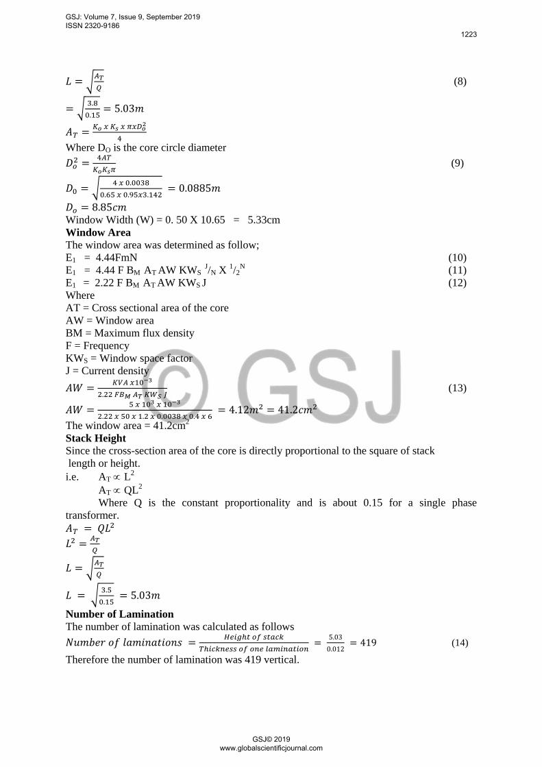
√
(8)
√
Where DO is the core circle diameter
(9)
√
Window Width (W) = 0. 50 X 10.65 = 5.33cm
Window Area
The window area was determined as follow;
E1 = 4.44FmN (10)
E1 = 4.44 F BM AT AW KWS J/N X
1/2
N (11)
E1 = 2.22 F BM AT AW KWS J (12)
Where
AT = Cross sectional area of the core
AW = Window area
BM = Maximum flux density
F = Frequency
KWS = Window space factor
J = Current density
(13)
The window area = 41.2cm2
Stack Height
Since the cross-section area of the core is directly proportional to the square of stack
length or height.
i.e. AT L2
AT QL2
Where Q is the constant proportionality and is about 0.15 for a single phase
transformer.
√
√
Number of Lamination
The number of lamination was calculated as follows
(14)
Therefore the number of lamination was 419 vertical.
GSJ: Volume 7, Issue 9, September 2019 ISSN 2320-9186
1223
GSJ© 2019 www.globalscientificjournal.com

Design of an Oscillator Using Sg3524
R5 and C2 connected at pin 6 and 7 of the IC SG3524 respectively determine the
frequency of oscillator. Using equation below we determine the value of the
unknown parameter.
(15)
Assume C2 = 104 x 10-12
F and the require frequency F=50Hz
Therefore C1 = 1.18 = 226933F
104x10-12
x50
The IC SG3524 is used in the inverter. The IC is used to generate the 50Hz frequency
required by the inverter. A DC supply is given to the pin 15 of the SG3524 through
Regulator. The pins 4,5,10 and 14 are connected to the negative terminal of the battery. The
pins 6 and 7 are the oscillation section pins. The frequency produced by the IC depends on
the value of the capacitor and resistor connected at these pins. The capacitor (104pf) is
connected to pin 7. This capacitor decides the 50Hz frequency output by the IC. Pin 6 is the
timing resistance pin. The resistance at this pin keeps the oscillator frequency constant. A
preset variable resistor (10K) is connected to ground from pin 1 of the IC. This preset is used
so that the value of the output current can be adjusted to a constant (40-50amps). A fixed
resistance of 4.7K is connected in series with the variable resistor as shown by the relation.
Let R5 = RT and C2 = CT
Where f is the frequency in Hz, RT is the total resistance at pin 6, and CT is the total
capacitance at pin 7.
Therefore, to obtain a frequency of 50Hz
Given CT = 104pf
RT = 1.30 = 250000kΩ
104x10-12
x50
Therefore, RT must be varied at 100k to obtain a frequency of 50Hz. In our design we used a
variable resistor of 100k.
Signals generated at the oscillator section of the flip-flop section of the IC. This section
converts the incoming signals into signals with changing polarity in this signal, changing
polarity means when the first signal is positive, the second would be zero and when the first
becomes zero, the second would be positive. To achieve a frequency of 50Hz, this process
most repeat every 50time per second i.e a pulsating signal with 50Hz frequency is generated
inside the flip-flop section of the IC.
This 50Hz frequency alternating signal has an output at pin 13 of the IC. Since the reference
voltage for the error amplifier (pin2) is set to 2.5V using voltage divider.
Therefore voltage supplied to pin 1 said to be 2.5V.
Using voltage divider
Assume R7 = 4700
Vpin 1 = 2.5V
R4 = 4700 or 4.7kΩ
(16)
Rs = R5, not that Vout is positive value which is equals 12v in our design. Require
GSJ: Volume 7, Issue 9, September 2019 ISSN 2320-9186
1224
GSJ© 2019 www.globalscientificjournal.com

voltage at pin 2 equals 2.5V
Assume R2 = 1kΩ
(17)
Taking preset R3 as 10kΩ R2 = 0.631k .
Elaborate Design of Project
Once the load has been established in the transformer then the current demand in the
secondary and primary coil is established.
Primary coil: This is so designed so that it has a lager turn ratio as compared to that of the
secondary for the needed current output. The coil is of smaller diameter of 2.35mm (i.e.
gauge 13)
Secondary coil: These are of larger diameter of 3.15mm (i.e. gauge 8) and smaller in
quantity, this is connected to the load where the high current demanding arc is needed. The
coils are well laminated and insulated to avoid losses of energy inform of heat. (i.e. eddy
current losses, hysteresis, etc.)
Transformer core: In this aspect of construction, mild steel sheets are cut into desire shape
(E) and size based the designed specification. This may also involve the determination of the
required number of lamination, these lamination are insulated from each other by a light coat
of core-plate vanish to reduce the eddy current losses. The laminations are then clamped
together with bolt and nuts. They are made to be tight so that vibration can be reduced to the
barest minimum. The thickness of the laminations used is 0.25mm for frequency 50Hz, the
laminations are assembled as shown below.
Figure 3: Lamination core
Controller Knob: This was designed in such a way that it can enable one to rotate the knob
clockwise to obtain the desire amperage.
Indicator Lamp: This gives a signal light were the machine is connected to a supply mains.
Fan: The fan is connected to the machine to look the temperature. It gets started once the
machine is connected to any of the supply mains.
Transformer Assembly
This whole lamination yoke were cut using a small cutting machine, this was done by setting
the lamination on a table vice with the vice tightened to properly hold and compress the
lamination which are arranged in such a way that they overlap equally at the edges, welder
together minimize noise (hum), with associated loss effect.
The primary coil and secondary coil which are wound on the plastic form are inserted in to
the lamination, which is in form of E-shaped lamination and then stacked to give a
rectangular shape, the primary and secondary end coils where brought through the lead
connection, the primary leads serves as the input of the transformer while the secondary lead
were connected to the welding tongue.
W 8 inches
L
L Y
B
1.2CM
GSJ: Volume 7, Issue 9, September 2019 ISSN 2320-9186
1225
GSJ© 2019 www.globalscientificjournal.com

Ventilation Handler
earth base
welding gun
Controller
Casing
Indicator lamp
DC supply
AC supply
Welding cable
Fan
Finally, the transformer was mounted inside the metal case called enclosure (covered), the
metal case was constructed out of metal sheets the transformer is mounted inside the metal
sheet to avoid vibration which may also result to humming sound.
All other accessories were linked, connected or attached and these includes the input and
output leads, IC oscillator, inverter circuit, rectifiers, capacitor, resistor, diode, inductance,
welding and earthing cables, electrode holder attached to the welding cable and fan for
cooling the system. As well as room for ventilation purpose. The casing arrangement is
shown in figure 3.
Figure 4: Casing arrangement
Principle of Operation
This paper had shown a high bridge hyb arc welding machine. The designed project is
220Votl AC power mains and 24V DC batteries main supply. The transformer TR consist of
two windings, the primary and secondary parts. The primary winding is connected to an AC
input supply of 220V and the secondary winding of 24V is a central tapped full wave rectifier
circuit. This D1-D4 6A diode x 8 rectifier the output 24V to +24V DC, the +24Volt is fed to
the regulator and the h-bridge inverter circuit. The regulator (7812) is provided to regulate the
+24Vdc to +12V needed to power the oscillator (SG 3524). The SG 3525 is used in the
oscillation section of the inverter. This IC is used to generate the 50Hz frequency required to
generate AC supply by the inverter. The pin 6 and 7 of the IC are the oscillation section pins.
The frequency produced by the IC depends on the value of the capacitor and resistor
connected at this pins. The capacity (2104 PF) is connected to pin 7. This capacity decides
the 50Hz frequency output by the IC pin 6 is the timing resistance pin. The resistance at this
pin keeps the oscillator frequency constant. The R5 is a (10k) present variable resistor
connected to the ground from pin 6 of the IC to adjust the output frequency. C1 is connected
in parallel with variable resistor and fixed resistor from pin 1 of the IC to ensure filtration of
decoupling. R3 (10k) variable resistor is used to control the output current. The +12 output
voltage from pin 13 of the IC oscillator is fed to R3 and R9 and R11 to the gate of MOSFET
(IRFP064) and NPN transistor (C9014). The 24Vdc battery supply the inverter circuit with
half bridge inverter to rectifier and filter. The two MOSFET (IRFP064) helps to control the
GSJ: Volume 7, Issue 9, September 2019 ISSN 2320-9186
1226
GSJ© 2019 www.globalscientificjournal.com

pulse generated from the oscillator. The two identical capacity voltage capacity (4700) 400V
C5 C6 helps to boost the current as required by the welding. An inductance connected in
series with C5 is used for filtering and to ensure a free flow flux from the output of the work
piece.
Table 1 Shows below is Maintenance Prescription Manual
Table 1 Maintenance Prescription Manuel
S/N FAULTS CAUSE(S) REMEDIES
1 Machine does not start No power supply
Incorrect supply voltage
Blown fuse
Check voltage, check
power replace fuse
2
Machine delivers current
but short down
Over loading power leads to
tooling or too small.
Ambient temperature too
high. Ventilation block.
Reduce welding current
Replace with large cable
Operate at reduced loads
3 Machine shocks Damage supply cable
Winding bridging to core
Change supply cable.
Insulate winding or
replace windings.
4
Electrode holder heats
excessively.
Partial contact between
holder and welding cable.
Change supply cable.
Insulate winding or
replace windings.
Ensure light contact
between holder to
welding cable.
5 Machine vibrates
excessively.
Wrong huge of electrode. Use proper gauge of
electrode.
Retighten lamination.
6 Joint will no melt
properly.
Current too low.
Supply voltage too low.
Increase or adjust the
controller knob
(regulator)
7 Welding low and spatters
excessively.
Current setting too high.
Incorrect electrode used.
Check setting and output
with dimension.
8 Machine overheating. Overloading wrong
connection.
Stop machine
immediately.
Check the switch and
reduce welding.
Precautions
Ensure that the cooling fan is working
Check the condition of the electrode holder for proper best insulation and good
electrical contact with the electrode.
Check if the welding cables are electrically continuous.
Using the proper glass recommended for welding machine.
GSJ: Volume 7, Issue 9, September 2019 ISSN 2320-9186
1227
GSJ© 2019 www.globalscientificjournal.com

4. TESTING, RESULT AND DISCUSSION
Testing
Table 2: Table of testing results
Figure 5: Pictorial diagrams
Physical specification of the machine
Height = 22mm
Length = 32mm
Width = 24mm
Result
After the construction, open circuit and short circuit test were carried out. The physical
working of the machine was also carried out.
The open and short circuit tests enable us to determine the efficiency, power factor and
voltage regulation of the transformer, which are 96%, 73% respectively. Table 2 shows the
testing results details
Discussion
After the design and construction, open circuit and short circuit test were carried out. The
physical working of the machine was also carried out.
The tongs of the electrode holder grip the electrode tight for different job position; hence no
arcing effect was noticed on the tong. Arc production with the different gauge of electrode
was very satisfactory for the metal works.
It has good and high operational efficiency and test shown that the design specified the
anticipated requirement.
Note: If 24Vdc 200AH batteries used is fully charged, the machine will last on load at 8hours
during operation.
Power supply Input voltage Output voltage Input current Output current
DC Battery 24V 50V 20A 20A
AC Mains
220V
50V
35A
50A
GSJ: Volume 7, Issue 9, September 2019 ISSN 2320-9186
1228
GSJ© 2019 www.globalscientificjournal.com

5. CONCLUSION
Conclusion
The design and construction of an hybrid single phase arc welding machine has been
successfully presented in this research.
The 24volt output from the transformer rectified to DC and regulated with (7812 regulator) to
12volt which is needed by the IC SG3524 oscillator to supply an out to the inverter circuit.
The inverter helps to control the 24volt batteries to a required voltage/current needed by the
welding machine. An inductance (current transformer) is connected in series with the inverter
to give free flow of flux at the welding output. A 10k variable resistor is connected across the
oscillator to vary the output current. The use of fan as a cooling medium enables the
transformer, oscillator and semiconductor component embedded in the circuit to operate on a
continuous duty cycle.
The successful completion of this research has broken the mystery behind transformer
construction.
The study will be of great importance to Engineers, Technologies, Technicians, Artisans and
those involved in metal work business.
Recommendations
It is here by recommended for anyone who wishes to improve on this paper, emphasis should
be made on the improvement of the efficiency of this machine. This can be made by
installing solar panel to charge the 24volt DC batteries to have a continuous welding process.
It is also recommended to improve on the power rating of this machine precisely the DC
power outage to prolong the operating hours.
REFERENCES
Aghakhani, M., Ghaderi, M. R., Jlilian, M., & Derakshan, A. A. (2014). Combined effect of
TiO2 nano-particles and welding input parameters on the hardness of melted zone in
submerged arc welding by fuzzy logic int. J. Adv. Manufacturer technology, 70, 63-
72.
Asiwe, U. M., Edem, A. and Edeafeadhe, G. (2018). Design and Construction of an Electric
Arc Welding Machine’s Transformer. Electrical /Electronic Engineering Department,
Delta State Polytechnic, Otefe-Oghara, Nigeria. Published @International Journal of
Trend in Scientific Research and Development (IJTSRD) International Open Access
Journal 2(6). [email protected]
Bhujbal, V. D., & Tadamalle, A. P. (2013). Optimization of laser welding process by fuzzy
logic technique. International journal of engineering science and innovative
technology, 2(4), 221-227.
Chen H. C., Pinkerton, A. J., Li, L., Liu, Z., & Mitry, A. T. (2011). Gap-free fibre laser
welding of Zn-coated steel on Al alloy for light-weight automotive applications,
Materials and Design, 32(495).
Frank A. (2003). Welding aluminum with inverter-based power supplies
https://www.thefabricator.com/article/aluminumwelding/welding-aluminum-with-
inverter-based-power-supplies
Ibrahim, I. I. Adamu, B. I. (2016) Design and Construction of a Welding Machine with a
Variable Current Selector . Department of Physics, Federal University Dutse, Jigawa
GSJ: Volume 7, Issue 9, September 2019 ISSN 2320-9186
1229
GSJ© 2019 www.globalscientificjournal.com

State International Journal of Pure & Applied Sciences.Vol.6No.2. Published by
Oxford Research and Publications
Kikani P. (2016) Welding as sustainable manufacturing process for fabrication industries
https://www.researchgate.net/publication/297076951_Hybrid_welding_as_sustainable_manuf
acturing_process_for_fabrication_industries/citation/download
APPENDIX
Appendix A: Bill of Engineering Material and Evaluation S/N MATERIAL
DESCRIPTION
SPECIFICATION QUANTITY UNIT
PRICE(N)
TOTAL
(N)
1 Electrode holder 600A 1 1000 1000
2 Battery cable 10mm 3yard 265 700
3 Welding cable 10mm 4yard 250 1000
4 AC main supply cable 10mm 2yard 300 600
5 Metal sheet 1.6mm sheet ½ full size 2500 2500
6 Electrode (gauge 12) 1 300 300
7 Lamination (core) 1 14800 14800
8 Bobbin Wooden 4 100 400
9 Fuse 1 300 300
10 Round copper wire (input) S.W.G gauge 16 4kg 2600 10400
11 Flate copper wire (output) S.W.G gauge 11 3kg 2600 7800
12 Indicator lamp LED 1 200 200
13 Controller knob W.L 1 200 200
14 Paint Medium tin 1 500 500
15 Masking tape Abro 4 100 400
16 Cord insulator 300 300
17 Bolts 12mm 4 120 480
18 Nut and washer 8mm 14 40 560
19 Screw 5mm, 3mm 30 300 300
20 Cooling fan 015Amp 24W 1 1000 1000
21 Cable lock 10mm 2 100 200
22 IC oscillator unit SG3524 3800
23 MOSFET IRFP064 2 2500 5000
24 MOSFET Transistor C9014 1 2500 2500
25 Power capacitor 4700, 400V HCG 2 4500 9000
26 Vanish 1litre 500 500
27 h-bridge rectifier 6Ax8, 6Ax5 1800
28 Logistic 6000
TOTAL 72,240.00
Appendix B: Interior view of the whole project
GSJ: Volume 7, Issue 9, September 2019 ISSN 2320-9186
1230
GSJ© 2019 www.globalscientificjournal.com

Appendix C: Exterior view of the whole project
GSJ: Volume 7, Issue 9, September 2019 ISSN 2320-9186
1231
GSJ© 2019 www.globalscientificjournal.com