· Created Date: 6/4/2014 7:11:00 PM
35
www.bcamcnc.com www.bcamlaser.com [email protected] Tel:0086-18615257636 YAG-BCJ1325-600W Metal Laser Cutting Machine Operation Manual ( Please read the manual carefully before the machine is installed and used ) BCAMCN Machinery Co., Ltd.(CHINA)
Transcript of · Created Date: 6/4/2014 7:11:00 PM
www.bcamcnc.com www.bcamlaser.com [email protected] Tel:0086-18615257636
YAG-BCJ1325-600W
Metal Laser Cutting Machine
Operation Manual(Please read the manual carefully
before the machine is installed and used)
BCAMCN Machinery Co., Ltd.(CHINA)
Operation Manual of YAG-BCJ1325-600W
2www.bcamcnc.com www.bcamlaser.com [email protected] Tel:0086-18615257636
InstructionMetal Laser Cutting Machine
The respect customer,welcome you to choose the
YAG-BCJ1325-600W Metal laser cutting machine produced by Shanda
Luneng Information Technology Co., Ltd!
Please read the manual carefully before using the machine, and use,
maintenance or repair the machine according to the regulations of this
manual strictly.
The illustration on wiring mode, parameter, performance, structure,
working principle and application requirement are given in the manual to
ensure that the YAG-BCJ1325-600W Metal laser cutting machine can be
used normally. The technical materials on using method, maintenance, and
problem analysis are provided simultaneously.
Customer please notes that all the data and illustration are provided
based on current product. If the manual content is inconsistent with the
product, take the product sample as standard please.

3
Operation Manual of YAG-BCJ1325-600WLaser Cutting Machine
www.bcamcnc.com www.bcamlaser.com [email protected] Tel:0086-18615257636
Safety precautions:Not
beenforceable
contents
Prohibit the use of the machine in the placewhere there is water, corrosion or flammablegas.
Can cause fire accident.
Prohibit some combustible substance aroundthe machine.Prohibit the use in the place where there isstrong, fierce vibration impact.
Can cause electric shock,injury, fire accident.
Prohibit the use in the case that wire issubjected to oil, water immersion.
Can cause electric shock,injury, fire accident.
Placing the instrument panel around heater orheating element is prohibited.
Can cause fire accident,fault.
That the motor is directly connected to thecommercial power source is prohibited.Prohibit wiring or operating on the machine bywet hands.
Can cause electric shock,injury, fire accident.
Stretching out hand inside of the driver isprohibited.
Can cause injury, electricshock, accident.
Touching the moving parts in motion isprohibited.
Can cause accident.
That the motor is driven by external force isprohibited.
Can cause fire accident.
That wires and cooling water pipes aredamaged for excessive force, weight, orclamping is prohibited.
Can cause electric shock,fault, broken.
Placing heavy objects on the sheet cut isprohibited.
Can cause electric shock,fault, broken.
Don’t put on or off the main power frequently. Can cause accident.Be sure not to start or stop motor usingelectromagnetic contactor beside the mainpower.The wiring operation should be completed by aprofessional electrician.
Can cause accident.
Ensure that wires are connected well and thatenergized position was insulated by insulating
Cause electric shock, fireaccident, fault for wrong
Operation Manual of YAG-BCJ1325-600WMetal Laser Cutting Machine
4
www.bcamcnc.com www.bcamlaser.com [email protected] Tel:0086-18615257636
Mustimplem
entthe
contents
material. wiring, short circuit.Lifting machine, wiring or repairing should bedo after the power supply is cut off and assurethat there is no electric shock dangerous.
Charged operation maycause electric shock.
Wear the protective glasses with appropriatewavelengths, when operating machine.
Can cause decreased visionor blindness, and otherseriousconsequences.
Ensure that the ambient temperature andhumidity is in the allowing range.
Can cause injury, accidentfor improper installation,setting.The distance between the machines should be
within the prescribed scope.When a fault occurs, please remove the causeof the error and eliminate it. To ensure safety,can be allowed to restart.
If error causes is notremoved, injury accidentmaybe happen.
Being loosen during transport, screws shouldbe inspected and fastened before the machine isused.
If screws are loosen, whichmay affect the cuttingeffect and the service life.
Cut off power supply if the machine is not usedlong time.
Can cause injury accidentfor equipment error.
The product should be as a waste after the normal use, related electronic productsrecycling, reusing compliance with laws and regulations of relevant departments please.
Confirmation in open:Satisfying the high-speed,high precision and high performance requirements,
YAG-BCJ1325-600W is extremely simple in setting, adjustment, operation, been upgraded and
updated unceasingly, so anybody can be able to feel its high performance.
After box is opened, confirm following please:Whether it conforms to the product you ordered?
Whether the machine is damaged during transport?
Whether there is operation manual?
Whether there are other accessory equipment?
If the product content discrepancies, please contact with the
agent or our company.

Operation Manual of YAG-BCJ1325-600WMetal Laser Cutting Machine
4
www.bcamcnc.com www.bcamlaser.com [email protected] Tel:0086-18615257636
Table of contents
1. The operation manual of main machine system----------------------------------6
1.1. Structure and working principle of the laser cutting machine-----------6
1.2. Main technical parameters of the laser cutting machine------------------8
1.3. Installation and debugging instructions of the laser cutting machine --9
1.4. Adjustment of laser resonator cavity optical path and attentions -----10
1.5. Operational procedure of the laser cutting machine --------------------13
1.6. Daily use and maintenance of the laser cutting machine ---------------15
2. Appling instruction of laser power -----------------------------------------------19
3. Appling instruction of laser cooling system ------------------------------------25
Appendix
I. Cutting parameters ------------------------------------------------------------------29
II. The signal wiring ------------------------------------------------------------------30
Ⅲ. The servo signal wiring ----------------------------------------------------------31
Ⅳ. Pneumatic connection diagram--------------------------------------------------32
Ⅴ. Lubrication connection diagr-----------------------------------------------------33
1. The operationmanual of main machine system1.1. Structure and working principle of the laser cutting machine
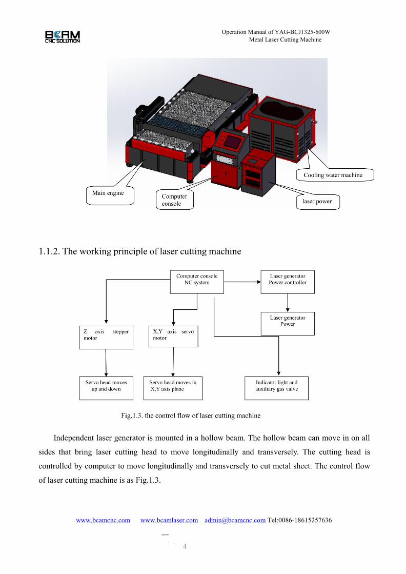
1.1.1. Laser cutting machine structureThe solid laser cutting machine is composed mainly of main machine, cooling water machine,
and laser power supply and computer console.

Operation Manual of YAG-BCJ1325-600WMetal Laser Cutting Machine
4www.bcamcnc.com www.bcamlaser.com [email protected] Tel:0086-18615257636
Structure instruction:
1) YAG laser generator and optical path system are mounted on a hollow beam. Laser cutting head
optical path is connected with laser generator optical path and the laser cutting head optical path can
be adjusted in cutting head. The protective cover need to open when laser generator optical path is
adjusted.
2) The travel switches in x and Y axes directions are mounted on base and cross rail. The protective
cover should be opened when travel switch is repaired.
Operation Manual of YAG-BCJ1325-600WMetal Laser Cutting Machine
4
www.bcamcnc.com www.bcamlaser.com [email protected] Tel:0086-18615257636
1.1.2. The working principle of laser cutting machine
Independent laser generator is mounted in a hollow beam. The hollow beam can move in on all
sides that bring laser cutting head to move longitudinally and transversely. The cutting head is
controlled by computer to move longitudinally and transversely to cut metal sheet. The control flow
of laser cutting machine is as Fig.1.3.

Operation Manual of YAG-BCJ1325-600WMetal Laser Cutting Machine
4
www.bcamcnc.com www.bcamlaser.com [email protected] Tel:0086-18615257636
No. Item name Parameters Units
1 Machine name Small format solid laser cutting machine
2 Laser cutting machine model YAG-BCJ1325-600W
3 Laser wave length 1064 nm
4 Laser pulse frequency 0-500(continuously adjustable) Hz
5 Input power of laser power 18 kw
6 Cooling water machine power 5 P
7 X, Y axis travel 2500×1300 mm
8 Z axis travel ≤80 mm
9 X, Y axis positioning accuracy +/-0.05 mm/m
10 X, Y axis repeat positioningaccuracy +/-0.05 mm/m
11 X, Y axis rapid traverse speed ≤15 m/min
12 X, Y axis maximum cuttingspeed 4 m/min
13 Minimum cutting width 0.15 mm
14 Target positioning Red light indicates
15 Blowing protection gas model Concentricity
16 Control system BaiChu laser cutting control software
17 Graphic format Dxf、Ai、Plt
18 Drive mode Yaskawa servo motor control
19 Continuous working timesuggest≤16H(Continuous 24
hours) H
20Maximum cutting thickness(ordinary carbon steel) 8 mm
21 Suitable for cutting materials Stainless steel, carbon steel, aluminum, copperand so on
22 Machine tool area (length ×width × height)
3.8×3.7×1.5 m
23 Overall power consumption ≤35 KW
24 Power demand 380V±5%/50Hz/100A
25 Consumptive materials xenon lamp, water, lens, auxiliary gas (nitrogen/ oxygen / compressed air
26 Laser safety grade Class IV
1.2. Main technical parameters of the laser cutting machineTable 1.1 Main technical parameters

Operation Manual of YAG-BCJ1325-600WMetal Laser Cutting Machine
9
www.bcamcnc.com www.bcamlaser.com [email protected] Tel:0086-18615257636
1.3 Installation and debugging instructions of the laser cutting machine
1.3.1 Installation conditions1) Site environment requirements:
a) The site should be clean and its space is ventilation, constant temperature dehumidifying (to
install air conditioning is recommended in the workplace), assuring that
environmental temperature in the workplace is about 10-30℃, relative humidity is not more than
90%RH,air dust is not more than 0.01g/m³, the foundation is flat without vibration.
b) Power supply: 380V±5%/50Hz/100A; Output power >40KW.
c) It is best to have tap water enter in installation place and to equip with high pure water
filtration water purifier.
2) Machine installation place layout
Complete set of equipment net area (3.8m×3.7m=14m2) combined with work activity area,
total area of the installation is 23 m 2 ( 4.8m×4.7m=23 m2)
1.3.2 Installation and debugging instructions1) First place the cutting machine according to the above figure, and then adjusts its level accuracy
using machine level.
2) Place the cooling water machine, computer console, and auxiliary gas bottle into designated
position in proper sequence, then adjusts them to be unstable rock.

Operation Manual of YAG-BCJ1325-600WMetal Laser Cutting Machine
9
www.bcamcnc.com www.bcamlaser.com [email protected] Tel:0086-18615257636
3) Connect the main machine, cooling water machine, computer console, and
auxiliary gas bottle together using cable, water pipe, the exhaust pipe according to the wiring layout.
4) After all connections are identified to be right, starts the cooling water machine and do water test
for 20 minutes, inspect whether there is water leakage, seepage.
5) Putting on the power of main machine and computer console, move X, Y, Z axis repetitive
individually by manual single axis control, observing whether there is abnormal phenomena, test
the action of “0” point switch and collision switch. Water cannot be interrupted to inspect whether
there is water leakage, seepage during test.
6) After above operation are identified to be right, putting on the power of laser, inputting test
cutting parameters, test cut sample. Observe the action of main machine, cooling water machine,
laser power, oxygen pressure gauge and exhaust blower, inspecting the cutting measurement and
quality. Installation and debugging is finished if there were no abnormal.
1.4 Adjustment of laser resonator cavity optical path and attentions
1.4 .1 Notice to adjust laser resonator cavity optical pathThe operator should frequently inspect output spot using infrared conversion film. If spot is not
uniform or energy decrease, laser resonator cavity optical path need to adjust timely to ensure laser
output quality.
Warning: The machine belongs to the fourth class laser equipment. Human skin will sustain
serious injuries for high power laser irradiation, especially, eye is irradiated by direct, reflection,
scattering, which lead to risk of blindness. Operator must know laser safety knowledge and wear
special laser protective glasses aiming at 1064nm wavelength in working time.
Attention: Open fire will be generated when high power laser direct exposure to wood and other
flammable materials. Absorption performance of ferrous metal materials is placed on laser output
optical path to end beam during adjustment to prevent fire accident.
Attention: Laser generator adjustment must be done by specially trained personnel, otherwise, laser
generator disorders or offset may cause the components on optical path damage.
1.4 .2. Adjustment process of the laser resonator1) Inspect collimated light source
Red light indicator is adapted in laser resonator target positioning, which is the standard of
optical path, so its accuracy must be ensured. Calibrate that the height of output red light and
remote control panel is highly consistent, and make the red light pass through the center of hole in
front baffle. If there is deviation, adjust optical path position by adjusting 4 screws on rack,
Operation Manual of YAG-BCJ1325-600WMetal Laser Cutting Machine
11
www.bcamcnc.com www.bcamlaser.com [email protected] Tel:0086-18615257636
inspecting that all screws should be fully tighten after adjustment is finished.
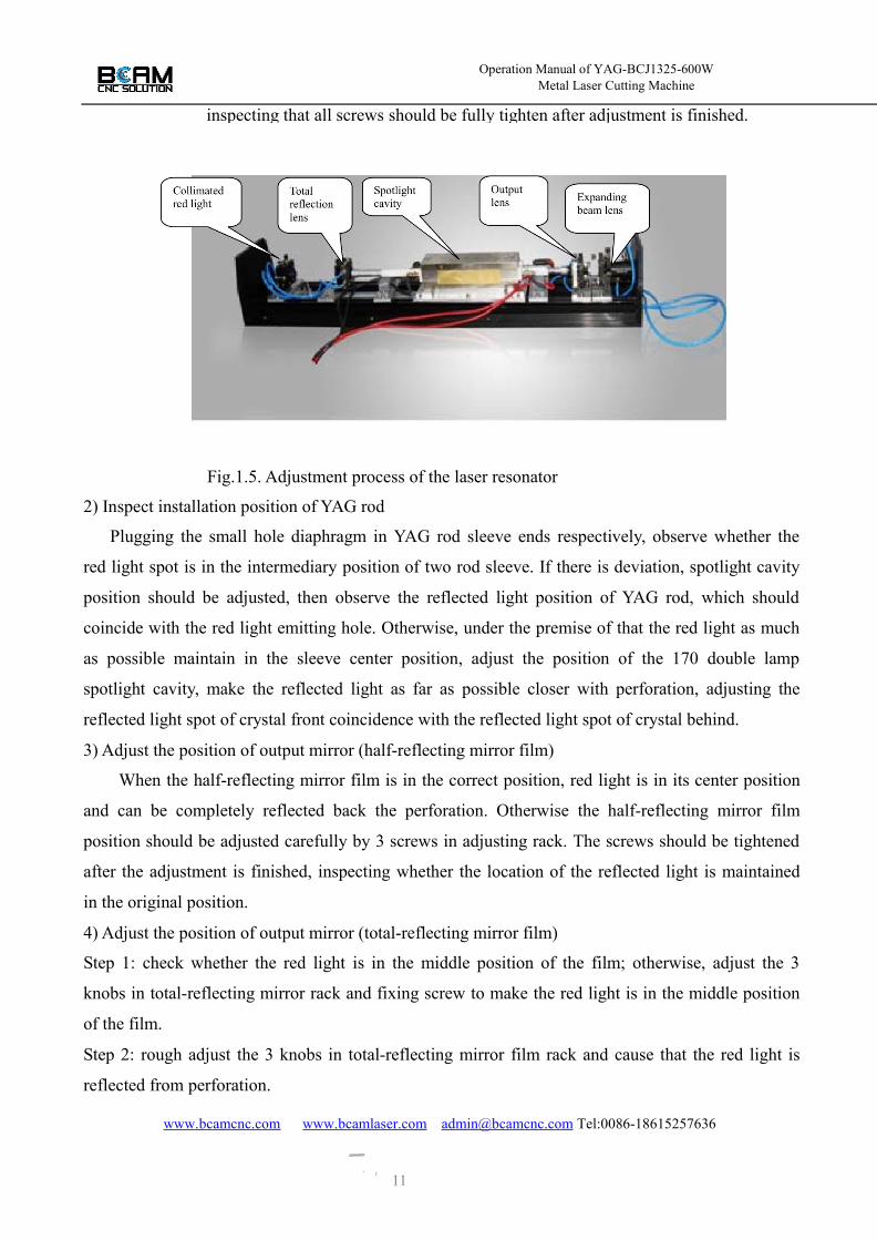
Fig.1.5. Adjustment process of the laser resonator
2) Inspect installation position of YAG rod
Plugging the small hole diaphragm in YAG rod sleeve ends respectively, observe whether the
red light spot is in the intermediary position of two rod sleeve. If there is deviation, spotlight cavity
position should be adjusted, then observe the reflected light position of YAG rod, which should
coincide with the red light emitting hole. Otherwise, under the premise of that the red light as much
as possible maintain in the sleeve center position, adjust the position of the 170 double lamp
spotlight cavity, make the reflected light as far as possible closer with perforation, adjusting the
reflected light spot of crystal front coincidence with the reflected light spot of crystal behind.
3) Adjust the position of output mirror (half-reflecting mirror film)
When the half-reflecting mirror film is in the correct position, red light is in its center position
and can be completely reflected back the perforation. Otherwise the half-reflecting mirror film
position should be adjusted carefully by 3 screws in adjusting rack. The screws should be tightened
after the adjustment is finished, inspecting whether the location of the reflected light is maintained
in the original position.
4) Adjust the position of output mirror (total-reflecting mirror film)
Step 1: check whether the red light is in the middle position of the film; otherwise, adjust the 3
knobs in total-reflecting mirror rack and fixing screw to make the red light is in the middle position
of the film.
Step 2: rough adjust the 3 knobs in total-reflecting mirror film rack and cause that the red light is
reflected from perforation.

Operation Manual of YAG-BCJ1325-600WMetal Laser Cutting Machine
11www.bcamcnc.com www.bcamlaser.com [email protected] Tel:0086-18615257636
Step 3: starting laser power supply, adjusting the current to be 60~80A, pulse width to be 0.5ms and
the repetition frequency to be 60Hz, step on the pedal switch one time and causes the pulse xenon
flash. Placing the infrared conversion film on the output mirror, observe laser outputting now.
Repeated adjusting the 3 knobs in total-reflecting mirror rack, make the output light spot to be best
circular and uniform.
Step 4: Check whether the laser coincide with red light. Fixing the infrared card on the front of laser
output lens as far as possible far from it, emitting a laser pulse, observe whether the light spot center
on paper coincide with the red light centre. If they don’t coincide, fine adjusting the red light to
cause light spot coincide with the red light, then fixing the infrared card on the place from output
lens 800--1000mm, check whether the laser coincide with red light again. If there is a higher degree
of coincidence, the laser generator is adjusted to the optimum state.
Step 5: Locking each adjusting knob, check whether the light spot in infrared card is good and
coaxial with the red light, otherwise, adjustment again is needed.
5) Adjusting the position of expanding beam lens
Adjusting the 4 screws in the expanding beam lens adjusting rack, cause that the enlargement
red light spot through hole is coincident with hole center in the front baffle light bar.
6) 45°refractor lens position
Adjusting the 3 screws in the 45°refractor lens adjusting rack, observe whether the red light is
in lens middle. Fixing the infrared card on the refractor lens, emitting a laser pulse, observe whether
the spot on photographic paper is consistent with the spot front the refractor lens. Minor adjustment
is needed if inconformity.
7) Adjust the position of the focusing lens in serve cutting head
Adjusting the 3 screws and fixing block in the focusing lens adjusting rack, make baseline red
light refracted by the 45°refractor lens rip into focusing lens center and laser beam emit from the
nozzle center. The nozzle would not block the laser power. Check carefully whether the protective
lens is cleaner, for contaminated lens will crack soon in using. Now the adjustment of laser resonant
cavity and output optical path shall be completed.
A point for attention:
At higher temperature or in a humid environment, observe whether the “condensation "
phenomenon is produced due to water temperature is too low in cooling water circulating pipeline
or laser focus cavity at any time. The “condensation” will cause YAG damage at crystal face to
cause that the output power decreases even no light, which must be paid attention to in using. If the
“condensation” appears, should stop the laser cutting machine immediately, wipe carefully the focus
light cavity lens using optical grade cotton with acetone or ethanol and inspect YAG optical surface
Operation Manual of YAG-BCJ1325-600WMetal Laser Cutting Machine
11
www.bcamcnc.com www.bcamlaser.com [email protected] Tel:0086-18615257636
conditions again, determining whether the YAG rod need to wipe. All is normal
circumstances the machine can start once again. The lower limit setting temperature of temperature
controller should be appropriate adjustable high before starting again.
Observe whether the titanium pipe of refrigeration system is frosted in normal operation. If
appear frost, which may be caused by that Freon in refrigeration system is too little. That should be
eliminated according to the “laser cooling system instruction”. Supplement Freon
and check whether there is leakage, which should be finished by related professionals.
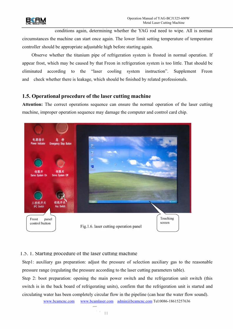
1.5. Operational procedure of the laser cutting machineAttention: The correct operations sequence can ensure the normal operation of the laser cutting
machine, improper operation sequence may damage the computer and control card chip.
1.5. 1. Starting procedure of the laser cutting machineStep1: auxiliary gas preparation: adjust the pressure of selection auxiliary gas to the reasonable
pressure range (regulating the pressure according to the laser cutting parameters table).
Step 2: boot preparation: opening the main power switch and the refrigeration unit switch (this
switch is in the back board of refrigerating units), confirm that the refrigeration unit is started and
circulating water has been completely circular flow in the pipeline (can hear the water flow sound).

Operation Manual of YAG-BCJ1325-600WMetal Laser Cutting Machine
14
www.bcamcnc.com www.bcamlaser.com [email protected] Tel:0086-18615257636
Step 3: set cooling water temperature: working environment
temperature and humidity in the refrigerating unit is arranged on the control panel. Circulating
water temperature is appropriate at condition that the optical devices are not condensation. The
specific operation method refers to “laser cooling system operation instruction”.
Step 4: starting the cutting machine: putting the key switch in front panel on the open position,
starting servo button, open laser power supply and set required parameters in the laser power
control panel. Refer to “laser power operation instruction”.
Step 5: pressing the start button to start the computer, pointing your mouse desktop CNC software
icon, double click the left mouse button to enter the software of numerical control cutting program
interface.
1) Point your mouse "load a file" at the bottom of the screen and double click the left mouse button,
the screen shows the “open” interface.
2) Selecting the folder saved by computer in the “change to the directory F2”, click the left mouse
button and select the graphics cutting procedures having been prepared for cutting, click the "open"
using left mouse button to bring up program having been programmed. The system owns some
simple graphics; you can click the “graphics management" under the "standard graphics" to choose
cutting parts needed and input parameter.
3) Pointing your mouse the "cutting compensation" icon at the bottom of screen, click the left
mouse button to do graphics automatic cutter compensation. Cutter compensation
parameter settings refer to “numerical procedures instruction”, pressing “enter” key after parameter
settings is finished.
4) Clicking the mobile key on the software interface, control the“X+” , “X-”, “Y+” and “Y-”
using the keyboard direction key to move the cutting head to a cutting position. Than the raise the
cutting head to a certain position, clicking “movement around frame” icon to inspect cutting range.
Now click the interface “run” icon using left mouse button to perform the laser cutting process.
At this point the programming process from starting to cut graphic is completed.

Operation Manual of YAG-BCJ1325-600WMetal Laser Cutting Machine
14
www.bcamcnc.com www.bcamlaser.com [email protected] Tel:0086-18615257636
Fig.1.7. Laser power control panel
1.5.2 Shutdown procedure of the laser cutting machine (contrary to starting order)1) First turn off the computer correctly.
2) Then turn off the laser power supply. After the computer is completely closed, press the select
key on the laser power supply panel keyboard. When "OFF" is displayed on the panel display, then
press the “confirm” key on panel keyboard. The machine whistles sound after system delay 5
seconds; when "P" is displayed on the panel display, LED indicator lamp is off. Press the red button
on the operating panel to cut off control circuit power supply.
3) In the conditions that laser power is completely closed and refrigerator compressor does not work,
close the composite button of refrigeration machine.
4) Turn down the laser power supply air switch, refrigerating machine air switch and the power
switch in proper order.
At this point the shutdown process of laser cutting machine process is completed.

Operation Manual of YAG-BCJ1325-600WMetal Laser Cutting Machine
14
www.bcamcnc.com www.bcamlaser.com [email protected] Tel:0086-18615257636
1.6. Daily use and maintenance of the lasercutting machine
1.6.1. Maintenance of the laser generatorAttention: Laser generator maintenance must be performed by specially trained personnel;
otherwise, it is easy to cause serious artificial damage. In order to ensure that the laser has been in a
normal working state, after two weeks of continuous work or stop using it for a period of time, the
YAG rod, dielectric film and lens protection glass, etc, should be inspected before starting to
determine that the optical component has no dust pollution, mildew and other anomalies. The above
phenomenon should be treated timely to ensure that the optical components will not be damaged in
intense laser irradiation. (If the machine is use in cleaner environment, the examination can be
extended to a month or even longer).
1.6.2. Maintenance of the cooling system1) Replace circulating water and clean water tank. Guarantee that the laser tube is filled with
circulating water before the machine working. Because water quality and water temperature directly
influence the service life of laser tube, regular replacement of circulating water and the water tank
cleaning is needed, which should be done per week.
2) Check interlocks protection circuit. In view of the characteristics of laser equipment, ultra warm
sound alarm, over-temperature interlock, flow switches interlock, liquid level protection interlock
and other protective measures are designed in this cooling system. Above protection circuit should
be checked often in using to ensure the normal function of effective. (the inspection work may be
done during replacement of circulating water)
1.6.3. Maintenance of mechanical drive systemMechanical system is composed mainly of the servo motor, ball screw, coupling and ball slide
guide, its stability ensure the laser processing accuracy. Ball screw, ball slide guide, and bearings
should be lubricated in time to ensure normal work.
Before starting the machine, pump oil a time by manual every day. Move at low speed
(speed below 2000 mm /s) for 10 minutes.
Linear guide way is one of the core parts of equipment, whose function is guide and support.
In order to guarantee high machining accuracy, linear guide way should be higher at guiding
precision and good at motion stability. A large number of corrosive dust and smoke will produced in
processing and this smoke and a large number of dust deposit on guide way surface long-term,
which has a great effect on processing accuracy. Because dust and smoke corrode guide surface,

Operation Manual of YAG-BCJ1325-600WMetal Laser Cutting Machine
14
www.bcamcnc.com www.bcamlaser.com [email protected] Tel:0086-18615257636
which shorten greatly the service life of the equipment, so the guide way surface
should be cleaned one time each half a month. Stop the machine when cleaning.
Screw and coupling connecting moving parts may be loosen after the motion system work a
period, which affects the mechanical motion stability, so observe whether there is noise or abnormal
phenomenon between driving components in the machine operation is very important. Problems
founded should be resolved in time. After a period of time screws should be fastened one by one
using tool. The first fastening is in the time that the machine is used for a month.
1.6.4. Electrical control system maintenance
Electrical control system includes laser power, servo motor drive, CNC motion card, PC
machine, control circuit board and a signal switch. Servo motor drive CNC motion card, PC
machine and control circuit board are combined as a whole and installed in the IPC cabinet. Laser
power supply and the control panel are installed in independent cabinet.
1) Requirements: ambient temperature is below 30 ℃, air dust is less 0.01g/ m2, dry.
2) Eliminate dust out of IPC cabinet and power supply cabinet with a clean brush or compressed air
filtered every three months.
(Attention: Please confirm that the cabinet power has completely closed, preventing high voltage
endanger personal safety)
3) Checked once per week whether each signal travel switch is sensitive and normal. Opening I/O
port test interface in Lasercut1.0 program, artificially toggling signal switch, watch whether each
signal display corresponding the symbol “√”in I/O port testing interface, otherwise, the signals
travel switch has been bad; It should be replaced timely so as not to lead to major accidents.
4) The complete machine is reliably grounded, series connection of ground wires between devices
are not allowed, grounding should be umbels. Otherwise the equipment operation will be seriously
disturbed.
1.6.5 The maintenance of gas and dust ventilation facilitiesCheck often whether the gas supply pipeline, quick joints, valves and connections leak gas,
including cutting auxiliary gas cylinders, valves, gas supply pipe, exhaust fan and wind pipe. Check
whether the exhaust fan is normal in operation.
1.6.6 The maintenance of the servo laser cutting head

Operation Manual of YAG-BCJ1325-600WMetal Laser Cutting Machine
14
www.bcamcnc.com www.bcamlaser.com [email protected] Tel:0086-18615257636
The servo laser cutting head, as a final execution device for laser cutting
processing, is a worn component, should standardized in operation, maintenance carefully in using to
keep it work in optimum state.
The following matters should be paid attention to in its use and maintenance.
1) Check carefully whether the protective lens is cleaner before each cutting, for contaminated lens
will crack and damage soon in use. If the protective lens is polluted, it should be cleaned carefully
with acetone or ethanol before using.
2) Check whether the center hole in the focus lens barrel nozzle is blocked or getting larger. If
blocking, should remove impurities for laser beam and smooth air flow through; if the center hole
get larger, same specifications nozzle should be immediately replaced and laser output optical path
is adjusted carefully to cause the laser beam pass through from the nozzle hole.
3) The maintenance and replacement of laser cutting head lens:a) The maintenance and replacement of the 45°refractor lens: Check the refractor lens damage degree.
If there is dust or dirt at lens, wipe clean the lens carefully using optical grade long-staple cotton with
acetone or ethanol; if lens is injury, and please replace it timely. Put on the finger sleeve contacting
lenses in above operation to avoid injury of lens. Installation order is opposite to this operation.
b) The maintenance and replacement of focusing lens: First disconnecting the connection between
the connecting cylinder and the focusing lens barrel, and then disconnecting the focusing lens
component, unscrew the connecting sleeve and take out all the parts under focusing lens barrel,
observe the two ends of focusing lens barrel and check the lens damage. Processing method is
described above.
c) The maintenance and replacement of protective lens: protective lens, belong to the consumable
parts, is installed near from laser cutting area to protect the focusing lens group, so it is easy to be
polluted or damage, regularly check and replacement is necessary. When replacing the lens, first
unscrew the connecting sleeve and take out all the parts under focusing lens barrel, unscrew the
clamping ring of protective lens, protective lens can be took out to maintain or replace.
Attention: the protective lens must be pressed by the clamping ring in protective lens installation to
protect the lens, so as to avoid leakage.
In addition: if the cutting quality drops suddenly in cutting, please check whether there is any dirt
or damage on the protective lens. If this situation happens, please clean or replace the protective
lens timely. Such as the protective lens fracture frequently, please check the output order of gas and
light, it must be ensured that the gas is output first and then the light is output.

Operation Manual of YAG-BCJ1325-600WMetal Laser Cutting Machine
14
www.bcamcnc.com www.bcamlaser.com [email protected] Tel:0086-18615257636
d) The replacement of laser nozzle: unscrew the laser nozzle locking ring, reinstall
the laser nozzle. After the installation is completed, you have a contact with laser nozzle by hand to
observe whether the cutting head is lifted up or down, which is mainly used to inspect whether the
signal line is good contact. Laser nozzle, belong to the consumable parts, must be regularly checked
and replaced.
1.6.7 The use and maintenance of serve cutting head height tracking systemAttention:Nozzle locking ring should be tighten by hand before cutting
The nozzle working height is set with height adjustable setting software of
the machine attaching. Working height is generally 1mm above the working face. Common failure
phenomena, causes and eliminating method of tracking cutting head are as following:
Table.2. Common failure phenomena, causes and eliminating method of tracking cutting headFailure
phenomenaCauses Eliminating method
The tracking
cutting
head do not
descend in
cutting.
1. Manual / automatic switch are not shifted or
automatic damage.
2. Tracking head nozzle connection is loosened.
3. The radio frequency cables connected from
nozzle to the control box is poor
contact or broken circuit.
4. Height knob in control box is set too large.
5. Sensitivity of control box is failure.
6. Transmission mechanism is
failure or loosening.
7. Drive motor is damage.
8. Height control box is damage.9. Relay damage.(control panel
behind the computer console)
1. Shift switch into automatic
status or replacement.
2. Tighten the nozzle locking nut.
3. Reconnect the cable or replacement.
4. Counterclockwise rotate the
knob to the right height.
5. Adjusted the sensitivity of control box.(refer to adjustment process of
height tracking cutting head)
6. Inspect synchronous belt
pulley connection.
7. Replace motor.
8. Replace control box.
9. Replace control relay.
The cutting
head continue
to shake up
and down in
cutting.
1. Height knob in control box is set too little.
2. Tracking head nozzle connection is loosened.
3. The radio frequency cables connected
from nozzle to the control box is poor contact
1. Counterclockwise rotate the
knob to the right height.
2. Tighten the nozzle locking nut.
3. Reconnect the cable.

Operation Manual of YAG-BCJ1325-600WMetal Laser Cutting Machine
14
www.bcamcnc.com www.bcamlaser.com [email protected] Tel:0086-18615257636
The
cutting head
suddenly rises
automatically
in cutting.
1. Tracking head nozzle connection is loosened.
2. Focusing optical path is not
straight, laser irradiates nozzle.
3. The radio frequency cables connectedfrom
nozzle to the control box is open winding.
1. Tighten the nozzle locking nut.
2. Readjust the focusing optical path.
3. Change the cable.
2. Appling instruction of laser powerBeing a real NC power supply, ZGM-SD (500Hz)-F type laser power supply is controlled by
single chip microcomputer. Laser wave pattern and parameter can be programmed by user through
the keyboard. This has following characteristic:
1) Control current: 100A-600A (signal lamp)
2) Pulse width: 0.2ms-20ms
3) Laser frequency: 1HZ-500HZ 0HZ is inching, 1HZ a step.4) The output power of power source:≤18KW
5) working environment: the environment temperature is below 30 ℃ and drying, air dust <
0.01g/㎡
There are sixteen digital displays on the laser power supply operation panel, the left three rows
(total 9) are parameter display, on the right, the topside (total 7) , LED light-emitting diodes, are
status indicator. The user should read the manual carefully before starting.
Following are introduction on ZGM-2-C type laser power operation.
2.3.1.Starting up
1) Attention: lifting power supply, check the power supply again before starting it.
a) Whether the printed circuit board is loosed or components are off signs.
b) Whether the terminals are loosened.
c) Whether the wiring (power line, connection lines between power box) are correct.
When make sure all connection is correct, first put on the isolating switch and than put the
power on. Press the “start button” key, control circuit is connected with power; the function display
displays the "P" now, which means system is normal. Pressing the "select" button and selecting "ON",
press "enter" key, the light is on by higher voltage. the machine whistling sound once after about two
minutes, the Nixie tube displays the "P" and the “pre-burning lamp” is light, which means
pre-burning success. If “NO” is displayed, press the "1" or "2" key, “U1”, “ON” or
“U2”, “ON” are displaced, which means that one lamp(single lamp work) is chosen to light. If the

Operation Manual of YAG-BCJ1325-600WMetal Laser Cutting Machine
14
www.bcamcnc.com www.bcamlaser.com [email protected] Tel:0086-18615257636
LED “pre-burning lamp” is not light or“ERR” information is displayed after whistle,
the reason may be that Xenon lamp is not connected, xenon lamp is bad or Xenon lamp electrodes
on the cavity with a discharge. Turning off laser power supply, resolve the faults then start it. If the
fault is not resolved, please contact the equipment seller.
2.3.2.Loading
Pressing the "load" button after pre-burning is successful; a group of parameters is called in
the digital display. The significance of each parameter will be showed. The leftmost L on the
function display is the first letter of the “LOAD”; the figures beside L are the group of laser
parameter ID whose range is 1-99. There are 99 different parameter combinations that can be called.
That can meet different cutting requirements.
Parameter on the right of function display express numerical number segment of synthesizes
laser waveform. Here give you follow introduction: Segmented programming is adapted to realize
the programming of arbitrary laser pulse waveform. Each segment correspond to a current and pulse
width, their combination form arbitrary waveform. 1-15 segments are allowed in this system. How to
program each segment parameter will be introduced in follow programming function.
Electrical current of the highest segment is showed on the current column of displayer. The
pulse width is the sum of all segment pulse width. Frequency refers to the frequency set by users
themselves. The maximum current value is 600A and the maximum pulse width sum is 15ms. If
users want to know the current and pulse width of each segment, pressing the “+.-” key, current and
pulse width of each segment can be called. P1—P“N” corresponding to each segment ID will be
showed on the frequency column.
In the loading condition, pressing the numeric keys, the different parameter group is called to
meet users. Pressing “enter” key, “U1”or“U2” is displayed, the system ask whether two lamps run
based on the parameter group. Pressing the “select” key, “U1” and “U2” changing each other on
displayer, means that each lamp emit light (run) based on different parameter input. Now pressing
the “time” key, “U1, H, U2” is displayed, that means two lamps emit overlapping light and the
working frequency can increase 1 time now. Pressing the “enter” key in the condition, emitting light
mode is selected and the machine whistling sound once, the “point” beside L is light, which means
that the parameters group in system is loaded successfully. Stepping on the pedal switch, light can
output. If the parameters set by user exceed the limit, for example, current is 800A, the parameters
can not be input working procedure, and the “point” beside L is not light, the system prompts the
supreme parameters can be set two times. At this time only can do is to return to the program state
to change parameters. If the frequency parameter is "0", the foot switch input is "point", emit laser a
Operation Manual of YAG-BCJ1325-600WMetal Laser Cutting Machine
14
www.bcamcnc.com www.bcamlaser.com [email protected] Tel:0086-18615257636
time pressing down foot switch a time. In general, pressing down foot switch, the
system will emit light based on the frequency set. If a set of numbers is input after the loading is
confirmed, that means preset laser pulse counting. In this case, pressing down the foot switch, laser
is emitted until the frequency reaches the user settings. If the frequency does not reach the preset
number, let go of the foot, then the laser stop immediately. The count volume is displayed in the
function displayer, count at descending mode, and top emitting laser when the volume is 0.
2.3.3. ProgrammingWhen a user wants to modify a group number of parameters, call these parameters, press the
“programming” key, the "L" change into the "P” in the display that is the first letter of “PROG”.
Press the “numeric” key; corresponding parameters group will be called. Pressing the “enter” key,
will enter the laser parameter programming. Pressing the “number” keys, different current and pulse
width can be set. Pressing the “option” key, the parameters set change between current and pulse
width; Pressing the “+,-” key, the parameters set change between segments. P1-P2 and corresponding
to segments ID are showed on frequency column. If the user wants to increase the
number of waveform segment, press the “programming” key one time, segment will
increase one until reaching 15. If the user wants to reduce the number of waveform segment, the
corresponding “pulse width” is set “0”, the segment will be deleted after the “enter”. Pressing the
“enter” key, indicator on frequency column is light, laser emitted frequency is set by pressing the
“numeric” key.
If press “enter” key again, the display frequency is defaulted. If the frequency needed is less
than 1Hz, the frequency change between 0.1 Hz —0.9 Hz by pressing the
“+,-“ key. Exit frequency changing after pressing "enter" key.
The laser emitted is asked again, after pressing the “enter” key, frequency
displayed is defaulted or that frequency is set again. Exiting the programming state will directly
enter the loading state.
2.3.4. CountingA laser counter is set to record a number of lights for the users, and it can be maintained even
after the power failure, then continue count next start up. The user can know about the service life
of the lamp through the counter. This count can be hidden, either be displayed in real time. If
real-time display is needed, press "count" key as long as the loading parameters are confirmed. The
function display count value records the optical frequency at any time. The counting real-time can
not be displayed when preset pulse counting is run. The laser counting can get only the operation
Operation Manual of YAG-BCJ1325-600WMetal Laser Cutting Machine
14
www.bcamcnc.com www.bcamlaser.com [email protected] Tel:0086-18615257636
stop. Pressing the “count” key two times continually, “CLEAN” is displayed, and
then pressing the “enter” key, count value is reset. Here please note!
2.3.5. TimingA timer is set to record the start time for the users. The operating procedure of the function is
the same as counting, so omit it here.
2.3.6. DeletionWhen "ON" or "OFF" is displayed on the function of display, pressing the "select" button,
"DEL" will be displayed, and then press the “enter” key to enter the deletion function. Pressing the
number keys to call the parameter number to be deleted, pressing the “enter” key. All the parameters
selected number is deleted, all the numbers in the set of parameters are 0, click the "select" button to
exit the deletion function.

Operation Manual of YAG-BCJ1325-600WMetal Laser Cutting Machine
14
www.bcamcnc.com www.bcamlaser.com [email protected] Tel:0086-18615257636
Attention: Once the parameter is deleted, it will not be recovered again, only toprogramming.
2.3.7. ShutdownIn the condition that high voltage is on, pressing the "select" button, when "OFF" is displayed
on the function display, pressing "enter”, the high voltage system is off. Because the lamp cools for
a while, pump shut down in 5 seconds and the machine whistle sound same time. The “p” is showed
display by nixie tube, LED indicator is out. The system is not responding key input in the process.
In the condition that main power supply is turned off, after control circuit is cut power, the isolating
switch behind the machine is pulled down finally.
The shutdown sequence is following. Select “OFF” from the “select” key and press the
“confirm” to turn off the main power, press “stop” button to turn off the control power and pull
down the isolating switch at last. In order to ensure the normal operation of equipment, the user
should strictly abide by the shutdown procedure!
2.3.8. Phase sequence protection and open-phase protection (Three-phase pulse laser
power supply)If the red light (the third from the back) in panel is light and lack of phase or phase sequence is
displayed. That means phase protection or lack of phase. In order to ensure the safe and stable
operation of power, the phase sequence protection and open-phase protection function is set. If the
phase is error or lack of phase, the red light in open-phase protection device lights. The power does
not work properly now.
Phase protection means that the protection function is finished automatically when the three
phase’s sequence of power is not right. User can change any two line position of the three phases,
the green lamp on protector is light, and can the power work normally.
Lack of a phase or two phase of three-phase power, the protection function of power supply is
carried out automatically. Users should carefully check whether the line connection is loosened. The
green lamp on protector is light, and can the power work normally.
Pay attention to phase sequence when initial installation of power
2.3.9. Other mattersLighting and starting up at every time, if pre-burning is success, the machine whistling sound,
the pre-burning indicator on panel is light, which means that high voltage circuit and the main
discharge circuit work normally. If the system fails to detect that xenon lamp light, control circuit
will ignite and trigger again after ten seconds. If the ignition is failure still, under-voltage indicating
lamp is bright and “ERR Un” is showed on function display, the power whistle sound continuously.

Operation Manual of YAG-BCJ1325-600WMetal Laser Cutting Machine
14
www.bcamcnc.com www.bcamlaser.com [email protected] Tel:0086-18615257636
That N is 1means lamp1 or power supply has problem. that N is 2means lamp2 or
power supply has problems and power supply whistling sound.
All green LED on panel shining express working performance; all the red LED shining are
warning failure.
When starting the machine, the attraction and disconnect of a relay is executed according to a
certain program, which has certain rules. If it is heard that the relay is not normal in starting, such as
jitter or irregular, that may be a printed plate loosening without inserted in position, Or the relay
itself has a fault.
2.4. Power supply of laser cutting parameters SettingRefer to the appendix 《laser cutting parameters table》
Operation Manual of YAG-BCJ1325-600WMetal Laser Cutting Machine
14
www.bcamcnc.com www.bcamlaser.com [email protected] Tel:0086-18615257636
3. Appling instruction of laser cooling system
The laser cooling system, using single chip automatic operation control mode, is high precision
temperature control of water chiller, having the advantages of simple operation, safe and reliable
running, convenient in installation, high efficiency and energy saving, simple and
convenient maintenance etc.
The main components are made of high quality brand element, Sanyo compressor imported,
compressor Controller for high precision automatic control of single chip, Selection of high quality
titanium tube evaporator made of aerospace materials, Condenser for brass aluminum alloy fin
composite cooling structure, circulating water pump are made of full stainless steel multistage
pump.
Unit system equip with high and low voltage protection of cooling pipes, compressor overheat
protection, current overload protection, phase loss and phase sequence protection anti leakage in
line with three-phase power, electric shock protection, liquid crystal displaying controller inching
adjustable, circulating cooling water PP cotton molecular filtration, protection alarming for high
water temperature or low flow, etc.
Technical indicators are as follows:
1) Working power supply: 3 phase 380V 50HZ
2) Temperature control precision: ≤±1℃
3) Temperature control range:0℃~50℃
4) lift of pump:47m
5) Water flow of pipe≥30L/min
6) Flow control switch≥25L/min, The electrical contacts are connected
7) Total power: 7.5KW
8) Refrigerating capacity: 18KW
9) Cold medium: R22
10) working environment: temperature≤36℃,air dust≤0.05g/㎡, well-ventilated.
In order to ensure the normal use of the equipment, please be sure to carefully read the
following instructions:
The unit is fixed well, then the circulating water pipe are connected firmly, Water tank filled
with pure water (in the initial injection should be unscrewed screw pump exhaust air until the water
flows, tight the screw) before using. Switch on power and the alarm signal line according to the

Operation Manual of YAG-BCJ1325-600WMetal Laser Cutting Machine
14
www.bcamcnc.com www.bcamlaser.com [email protected] Tel:0086-18615257636
technical requirements. Put on the power switch after the confirmation. At this
time if the red lamp of power lights means power supply phase sequence is correct, otherwise the
sequence is errors, to adjust the power phase sequence is needed. After phase sequence correct, set
the operating temperature, then the normal startup.
Note: equipment internal pump, compressor, fan sequence has been adjusted, not individually
adjusted; otherwise cause compressor, pump, etc, damage.
3.1. Maintenance1) Units should be placed in the shade ventilated good, there is no obstacle within wind inlet side
0.3 meters, maintain 1 meters space in outlet to facilitate heat dissipation.
2) Regular cleaning of condenser, evaporator, a water tank and water filter according to the usage
and working environment. Observe whether water filter cartridge is color, if the color should be
timely replacement of filters, and clean the water tank and a circulating waterway.
3) Keep the circulating water quality, water level. Change water in time and clean water way
carefully, if water is polluted. Replenish the distilled water or pure water, if the water level is low.
Do not add water or tap water, untreated water. Otherwise it will seriously pollute the water way
and influence laser efficiency.
4) Check the grounding reliability frequently, periodic fastens wiring fixing screws in the electrical
cabinet every three months.
5) The optical device to be cooled without condensation is suitable for circulating water temperature
settings. The specific temperature parameter setting refers to the environmental temperature and
humidity.
6) Ban set inclining over 300 when handling and placement, Ban that equipped withcirculation
water chillers are placed in 0 ℃ environment to avoiding freezing refrigeration cyclesystem.
3.2. Common fault analysis and troubleshootingFailure
phenomenaCauses Resolve method
1. No displayafter power is on
Power failure.Temperature controllermalfunction.
Troubleshooting, according to the
requirements of power supply.
Check whether there is 220V
voltage in the temperature control power
input terminal. If the

Operation Manual of YAG-BCJ1325-600WMetal Laser Cutting Machine
14
www.bcamcnc.com www.bcamlaser.com [email protected] Tel:0086-18615257636
2. Overload faultlamp is light
High and low voltageprotection ofrefrigeration system.Current overload ofcompressor protection.
High voltage protection unit is poor radiating heat,
press the manual reset button on the pressure
controller.
Lack refrigerant in low voltage protection system,
manual reset is needed also. Leak must be found after
reset, fill refrigerant after repairing; check whether the
compressor coil resistance is normal at the same time.
3. Phase faultlamp is light.
Power supply phasesequence error.
Any exchange of two power line.
4. Indicator lightflashes but doesnot refrigerate.
The thermostat is delay. Wait for 3-5 minutes before start it.
5. Water pumpworks,But the flow faultlamp is light.
Pipeline water flow islower than the flowswitch setting.There is air in pipe orpump.
Check whether there is blockage in the water tank
water pump entrance filter, a return water filter, and
pipe and remove them.
Loosen the top screw and empty air; until a large
amount of water is outflow tighten the screws last..
6. Inadequatecooling capacity.
Expansion valve opening
is too small or too big.
Refrigerant leakage
There is air in refrigeration
system.
Dirt of evaporator.
Excessive condenser dust.
Condensing fan fault.
Adjustment of expansion valve opening
Find leakage; fill refrigerant leakage after mending
leakage.
Pump vacuum and fill refrigerant again.
Cleaning the exterior surface of the evaporator.
Cleaning the condenser fins.
Repair or replace the fan.
7. Compressorfrosting.
Set the temperature is too
low or the thermostat is
bad.
Expansion valve opening
is too big.
System refrigerant too
much.
Expansion valve
temperature sensing bag is
in improper location.
Adjust the temperature or the replacement thermostat.
Adjustment of expansion valve opening.
Blow off excess refrigerant.
Re-pack up the temperature sensing bag.

Operation Manual of YAG-BCJ1325-600WMetal Laser Cutting Machine
14
www.bcamcnc.com www.bcamlaser.com [email protected] Tel:0086-18615257636
Appendix I Laser cutting parameters table
Material Laser Power supplyparameters Thickness Speed Auxiliary
gas
Gaspressure Remarks
carbonsteel
current pulsewidth frequency mm mm/min Mpa
100 1 320 1 2000 oxygen 1
120 1 210 2 1000 oxygen 1
120 1.2 200 3 800 oxygen 0.6
150 1.5 110 4 600 oxygen 0.4
180 1.8 78 5 400 oxygen 0.1-0.2
180 1.8 78 6 300 oxygen 0.1-0.2
180 1.8 78 7 100 oxygen 0.1-0.2
180 1.8 78 8 50 oxygen 0.1
stainlesssteel
100 1 320 1 2000 oxygen 1
120 1 210 2 1000 oxygen 1
120 1.2 200 3 800 oxygen 0.2-0.6
180 1.5 100 4 600 oxygen 0.2-0.6
180 1.8 78 5 500 oxygen 0.2-0.6
180 1.8 78 6 300 oxygen 0.2-0.6
1. This table is for reference only.2. The parameter is based on focus lens (f=120).3. Thick materials like 7-8mm carbon steels are not suggested to cut frequently.

Operation Manual of YAG-BCJ1325-600WMetal Laser Cutting Machine
14
www.bcamcnc.com www.bcamlaser.com [email protected] Tel:0086-18615257636
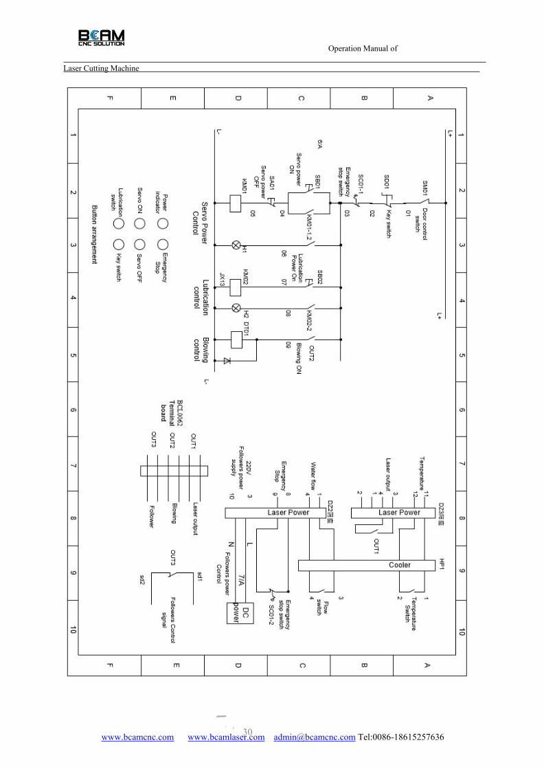
AppendixⅡ The signal wiring
Operation Manual ofYAG-BCJ1325-600W
30www.bcamcnc.com www.bcamlaser.com [email protected] Tel:0086-18615257636
Laser Cutting Machine
Operation Manual ofYAG-BCJ1325-600W
Metal Laser Cutting Machine
31
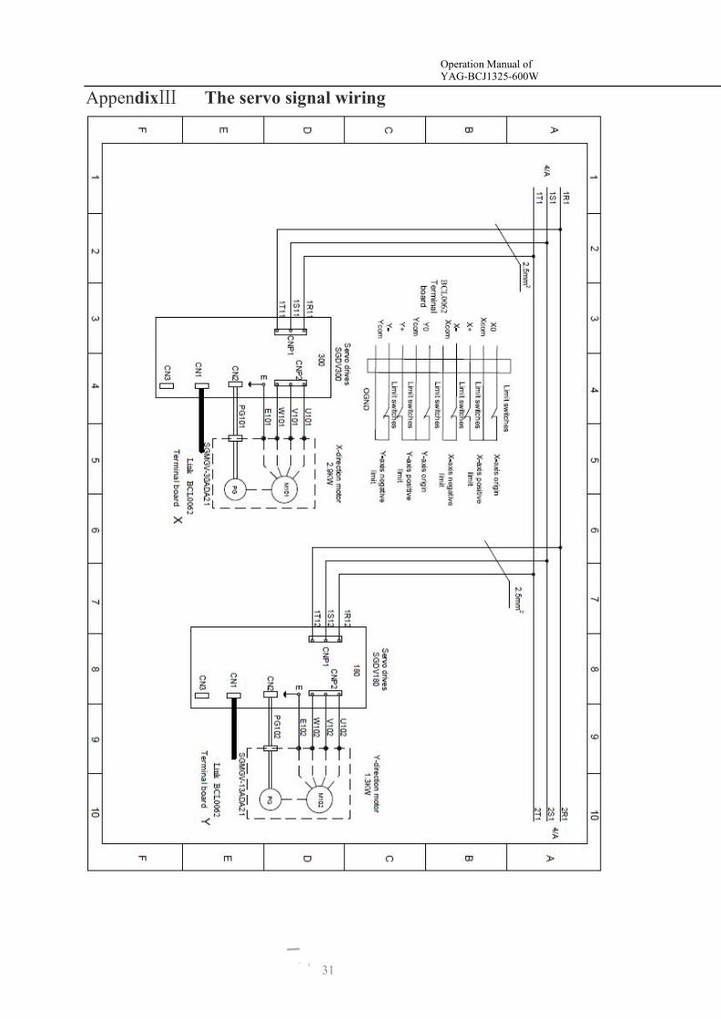
AppendixⅢ The servo signal wiring
Operation Manual ofYAG-BCJ1325-600W
Metal Laser Cutting Machine
31
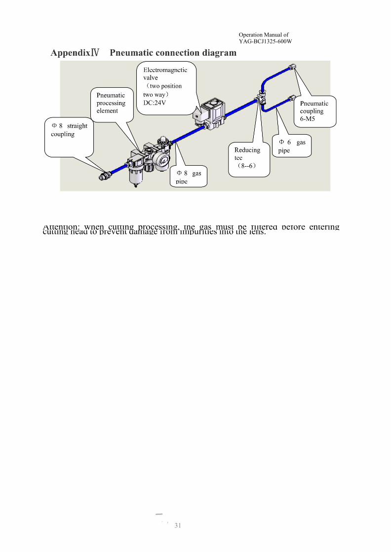
Attention: when cutting processing, the gas must be filtered before enteringcutting head to prevent damage from impurities into the lens.
Operation Manual ofYAG-BCJ1325-600W
Metal Laser Cutting Machine
31
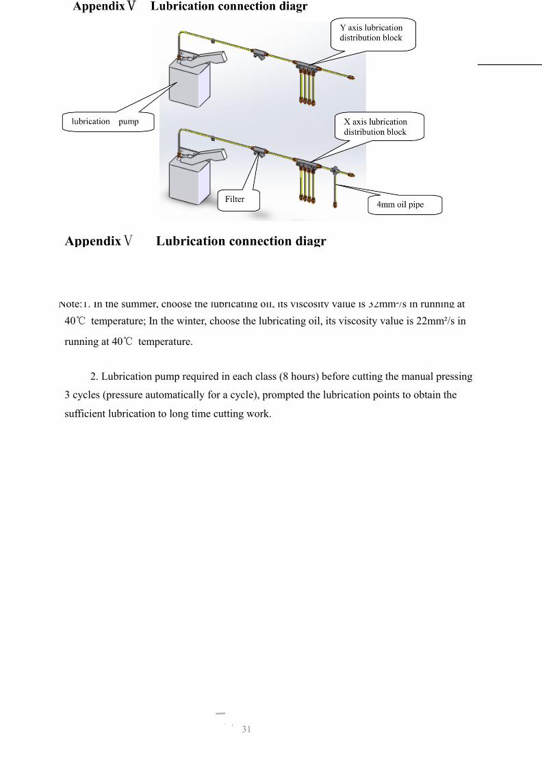
AppendixⅤ Lubrication connection diagr
Note:1. In the summer, choose the lubricating oil, its viscosity value is 32mm²/s in running at40℃ temperature; In the winter, choose the lubricating oil, its viscosity value is 22mm²/s in
running at 40℃ temperature.
2. Lubrication pump required in each class (8 hours) before cutting the manual pressing
3 cycles (pressure automatically for a cycle), prompted the lubrication points to obtain the
sufficient lubrication to long time cutting work.

2