© Copyright 2019
59
Transcript of © Copyright 2019


FAA Approved AFMS or Supplemental AFM for the Garmin G3X Touch EFIS 190-01754-01 Rev. 4
© Copyright 2019 Garmin Ltd. or its subsidiaries
All Rights Reserved
Except as expressly provided herein, no part of this manual may be reproduced, copied, transmitted,
disseminated, downloaded or stored in any storage medium, for any purpose without the express prior
written consent of Garmin. Garmin hereby grants permission to download a single copy of this manual
and of any revision to this manual onto a hard drive or other electronic storage medium to be viewed and
to print one copy of this manual or of any revision hereto, provided that such electronic or printed copy of
this manual or revision must contain the complete text of this copyright notice and provided further that any
unauthorized commercial distribution of this manual or any revision hereto is strictly prohibited.
Garmin International, Inc. 1200 E. 151st Street
Olathe, KS 66062 USA Telephone: 913-397-8200
www.garmin.com

190-01754-01 Rev. 4 FAA Approved AFMS or Supplemental AFM for the Garmin G3X Touch EFIS
Page i
Garmin International, Inc
Log of Revisions
FAA Approved
AIRPLANE FLIGHT MANUAL SUPPLEMENT
or
SUPPLEMENTAL AIRPLANE FLIGHT MANUAL
for the
GARMIN G3X TOUCH ELECTRONIC FLIGHT INSTRUMENT SYSTEM
REV
NO. PAGE NO(S) DESCRIPTION
DATE OF
APPROVAL FAA APPROVED
1 ALL Original Issue 03/15/19
Robert Murray
ODA STC Unit
Administrator
2 2-2, 2-5
Added limitation for
installations with an
autopilot other than
GFC500.
04/05/19
Paul Mast
ODA STC Unit
Administrator
3 1-5, 2-1
Added GPS 175 / GNX
375 as approved IFR
navigators.
5/30/19
Paul Mast
ODA STC Unit
Administrator
4 ALL
Incorporate system
software v8.60 and
associated hardware
changes.
12/20/19
Robert Murray
ODA STC Unit
Administrator

FAA Approved AFMS or Supplemental AFM for the Garmin G3X Touch EFIS 190-01754-01 Rev. 4
Page ii
This page intentionally left blank.

190-01754-01 Rev. 4 FAA Approved AFMS or Supplemental AFM for the Garmin G3X Touch EFIS
Page iii
Table of Contents
1 General .................................................................................................................. 1-1
1.1 G3X TOUCH GNSS (GPS/SBAS) NAVIGATION EQUIPMENT APPROVALS......................... 1-5
1.2 Abbreviations and Terminology ............................................................................................... 1-7
2 Limitations ............................................................................................................ 2-1
2.1 System Software Requirements ............................................................................................... 2-1
2.2 Standby Flight Instruments ...................................................................................................... 2-1
2.3 Navigation Systems for IFR Operations .................................................................................. 2-1
2.4 Databases ................................................................................................................................... 2-1
2.5 AHRS Operational Area ............................................................................................................ 2-2
2.6 Magnetic Variation Operational Area....................................................................................... 2-2
2.7 Navigation Angle ....................................................................................................................... 2-2
2.8 ADAHRS Normal Operating Mode ........................................................................................... 2-2
2.9 Aerobatic Maneuvers ................................................................................................................ 2-2
2.10 Other Autopilots ................................................................................................................... 2-2
2.11 Synthetic Vision ................................................................................................................... 2-2
2.12 Moving Maps ......................................................................................................................... 2-2
2.13 Terrain Display ..................................................................................................................... 2-2
2.14 Terrain Alerts ........................................................................................................................ 2-3
2.15 Traffic Display ....................................................................................................................... 2-3
2.16 Surface Operations .............................................................................................................. 2-3
2.17 Glide Range Ring ................................................................................................................. 2-3
2.18 Powerplant Gauge Markings ............................................................................................... 2-3
2.19 Weight and Balance ............................................................................................................. 2-3
2.20 Data link Products (SiriusXM, FIS-B, and Connext) ......................................................... 2-3
2.21 Glove Usage .......................................................................................................................... 2-4
2.22 Service Required .................................................................................................................. 2-4
2.23 Portable Electronic Devices ................................................................................................ 2-4
2.24 Kinds of Operations ............................................................................................................. 2-4
2.25 Placards ................................................................................................................................ 2-5
3 Emergency Procedures ....................................................................................... 3-1
3.1 ADC Failure (GSU 25) ................................................................................................................ 3-1
3.2 Attitude Failure (GSU 25) .......................................................................................................... 3-1
3.3 Attitude Aligning / Keep Wings Level ...................................................................................... 3-2
3.4 AHRS ALIGN .............................................................................................................................. 3-2

FAA Approved AFMS or Supplemental AFM for the Garmin G3X Touch EFIS 190-01754-01 Rev. 4
Page iv
3.5 Autopilot Abnormal Disconnect ............................................................................................... 3-2
3.6 G3X Touch Altimeter Barometric Window Cyan .................................................................... 3-2
3.7 EIS Failure .................................................................................................................................. 3-2
3.8 Erroneous Air Data or Attitude Information (G5 Standby Flight Instrument Installed) ...... 3-3
3.9 G3X Touch Failure Annunciations ........................................................................................... 3-3
3.10 Heading Failure, Loss of Magnetometer Data, or Magnetic Field Error ......................... 3-4
3.11 PFD Failure ........................................................................................................................... 3-4
3.12 Navigation Data Failure (GPS/VOR/LOC/GS) .................................................................... 3-4
3.13 TERRAIN ALERTS ................................................................................................................ 3-5
3.14 WARNINGS, CAUTIONS, and ADVISORIES ....................................................................... 3-6
4 Normal Procedures .............................................................................................. 4-1
4.1 BEFORE STARTING ENGINE ................................................................................................... 4-1
4.2 AFTER STARTING ENGINE ...................................................................................................... 4-1
4.3 COM Radio Tuning (Optional) .................................................................................................. 4-2
4.4 Lateral Navigation...................................................................................................................... 4-2
4.5 APPROACHES ........................................................................................................................... 4-3
4.6 Barometric Minimums Alert .................................................................................................... 4-14
4.7 TRANSPONDER Operation (Optional) ................................................................................... 4-14
4.8 Disable Electronic Stability Protection (ESP) ....................................................................... 4-15
5 Performance ......................................................................................................... 5-1
6 Weight and Balance ............................................................................................. 6-1
7 System Description .............................................................................................. 7-1
7.1 Primary Flight Instruments ....................................................................................................... 7-1
7.2 Vertical Deviation Indicators .................................................................................................... 7-3
7.3 HSI Annunciations ..................................................................................................................... 7-4
7.4 Course Deviation Indicator (CDI) ............................................................................................. 7-4
7.5 Display of PFD information on MFD ........................................................................................ 7-5
7.6 Engine Indication System ......................................................................................................... 7-5
7.7 Communication / Navigation / Surveillance System .............................................................. 7-5
7.8 Remote Transponder Interface ................................................................................................ 7-5
7.9 Minimum Altitude Display and Alerting .................................................................................. 7-6
7.10 AOA Probe (Optional) .......................................................................................................... 7-7
7.11 GAD 27 Wig Wag (Optional) ................................................................................................ 7-7
7.12 EIS Caution / Warning Lights .............................................................................................. 7-7

190-01754-01 Rev. 4 FAA Approved AFMS or Supplemental AFM for the Garmin G3X Touch EFIS
P a g e | 1-1
1 GENERAL
The information in this supplement is FAA-approved and must be attached to the Pilot’s Operating Handbook and FAA Approved Airplane Flight Manual (POH/AFM) when the airplane has been modified by installation of the Garmin G3X Touch Electronic Flight Instrument system in accordance with Garmin International, Inc. approved data, STC SA01899WI. The information in this supplement supersedes or adds to the basic POH/AFM only as set forth below. Users of the manual are advised to always refer to the supplement for possibly superseding information and placarding applicable to operation of the airplane. The G3X Touch provides one or more of the following functions:
• Primary Flight Display (PFD) – Provides attitude, air data, heading, and navigation information to the pilot.
• Multi-Function Display (MFD) – Provides pilot awareness of factors that may affect the overall
conduct of the flight such as advanced moving map including terrain, obstacle and traffic alerts, georeferenced FliteCharts® or Jeppesen® ChartView™ charts and SafeTaxi® airport diagrams.
• Engine Indication System (EIS) – Provides engine and airframe operating parameters to the pilot.
The G3X Touch is scalable with a variety of configurations made up of the 7” portrait GDU 470 and the 10” landscape GDU 460. Installations may consist of one or both display types in any combination from one to three displays (or up to four displays total in tandem cockpit aircraft). A minimum installation with a single display may be a standalone MFD or a PFD which can be split screened to provide both PFD and MFD functions. EIS can optionally be displayed on any GDU except a 7” portrait PFD. Only one display per cockpit can be installed as a PFD (any second or third display is an MFD).

FAA Approved AFMS or Supplemental AFM for the Garmin G3X Touch EFIS 190-01754-01 Rev. 4
P a g e | 1-2
Single 7” Portrait GDU (PFD with MFD in split mode, No EIS)
Single 10” GDU (PFD & MFD, EIS Optional)

190-01754-01 Rev. 4 FAA Approved AFMS or Supplemental AFM for the Garmin G3X Touch EFIS
P a g e | 1-3
Dual 7” Portrait GDUs (PFD & MFD, EIS Optional)
One 10” + One 7” Portrait GDU (PFD & MFD, EIS Optional)
FAA Approved AFMS or Supplemental AFM for the Garmin G3X Touch EFIS 190-01754-01 Rev. 4
P a g e | 1-4
These displays come with a built-in WAAS GPS receiver for VFR operations and native infrared touchscreen interface. The system can also interface with an IFR approved GPS navigator for IFR operations. PFD installations require the installation of a GSU 25 ADAHRS, GMU 11 magnetometer, GTP 59 temperature probe, and the GAD 27 voltage stabilizer (14V airframes with EIS). For all PFD installations in aircraft approved for IFR operations, standby instruments and an IFR approved navigation system are required. If the installation includes a separate PFD and MFD, reversionary backup is available should a failure of either display occur. In reversionary mode, the remaining G3X Touch display combines critical flight instrumentation with engine readouts (if installed) and navigation information in a single-screen consolidated presentation. If EIS functions are installed, they require the installation of a remote mounted GEA 24 Engine Airframe unit and associated engine sensors. MFD functions are supported by an internal GPS receiver or an external IFR GPS navigator interface. G3X Touch flight displays can be seamlessly integrated with a variety of radios, transponders, audio panels, ADS-B, SiriusXM ® data links, mobile devices via Garmin Connext ® and autopilot systems. Use of this supplement requires the installation of Garmin G3X Touch Electronic Flight Instrument hardware and system software version 8.0 or later FAA Approved software version in the aircraft. Pilots are advised to carefully review the contents of this Airplane Flight Manual Supplement before operating the airplane. The following table lists the Pilot’s Guide applicable to the respective system software version.
System Software Version Pilot’s Guide Part Number
8.0 or later 190-02472-00, Rev A or later
USE OF THE AFMS The following definitions apply to WARNINGS, CAUTIONS and NOTES found throughout the AFMS:
WARNING
Operating procedures, techniques, etc., which could result in personal injury or loss of life if not carefully followed.
CAUTION
Operating procedures, techniques, etc., which could result in damage to equipment if not carefully followed.
NOTE
Operating procedures, techniques, etc., which is considered essential to emphasize.

190-01754-01 Rev. 4 FAA Approved AFMS or Supplemental AFM for the Garmin G3X Touch EFIS
P a g e | 1-5
1.1 G3X TOUCH GNSS (GPS/SBAS) NAVIGATION EQUIPMENT APPROVALS
To support IFR navigation the G3X Touch must be interfaced to a compatible Garmin GPS or VHF navigator including the following:
• GNC 300XL / GPS 155XL *
• GNS 4XX(W) / GNS 5XX(W) / GNS 480 *
• GTN 6XX / 7XX *
• GPS 175 / GNX 375 *
• SL30
• GNC 255
• GNC 355/355A * * requires installation of GAD 29B ARINC-to-CAN converter In lieu of interfacing G3X Touch to a Garmin IFR navigator, an installation could maintain IFR capability by retaining non-Garmin GPS and/or VHF Nav radios along with their standalone dedicated CDI.
NOTE
Refer to the Airplane Flight Manual Supplement for the installed IFR approved GNSS Navigation System for approved operations.
When no external IFR navigator is connected, or when the internal G3X Touch GPS navigation source is selected by the pilot, the G3X Touch provides VFR flight planning capabilities and guidance on the HSI. A cyan ‘INT’ and magenta ‘VFR’ annunciation are displayed on the HSI when using the internal navigation function. When ‘INT’ and ‘VFR’ are annunciated, IFR operations are prohibited.

FAA Approved AFMS or Supplemental AFM for the Garmin G3X Touch EFIS 190-01754-01 Rev. 4
P a g e | 1-6
This page intentionally left blank.

190-01754-01 Rev. 4 FAA Approved AFMS or Supplemental AFM for the Garmin G3X Touch EFIS
P a g e | 1-7
1.2 Abbreviations and Terminology
The following glossary is applicable within the airplane flight manual supplement
AC Advisory Circular
ADAHRS Air Data Attitude Heading Reference System
ADC Air Data Computer
ADS-B Automatic Dependent Surveillance-Broadcast
AFCS Automatic Flight Control System
AFM Airplane Flight Manual
AFMS Airplane Flight Manual Supplement
AHRS Attitude Heading Reference System
ALT Altitude
AML Approved Model List
AMMD Airport Moving Map Display
AOA Angle of Attack
AP Autopilot
APV Approach with Vertical Guidance
ARINC Aeronautical Radio Incorporated
ATC Air Traffic Control
ATT Attitude
Baro Barometric
BC Back Course
CAN Controller Area Network
CB Circuit Breaker
CDI Course Deviation Indicator
CFR Code of Federal Regulations
COM Communication
DA Decision Altitude
DG Directional Gyro
ECS Electrical Control System
EIS Engine Indication System
ESP Electronic Stability and Protection
GA Go Around
GP Glide Path
GPSS GPS Steering
FAA Federal Aviation Administration
FAF Final Approach Fix

FAA Approved AFMS or Supplemental AFM for the Garmin G3X Touch EFIS 190-01754-01 Rev. 4
P a g e | 1-8
FD Flight Director
FIS-B Flight Information Service – Broadcast
FPL Flight Plan
FPM Feet Per Minute
GAD Garmin Adaptor Device
GDU Garmin Display Unit
GEA Garmin Engine and Airframe
GFC Garmin Flight Control
GMU Garmin Magnetometer Unit
GNC 255 Garmin Navigation and Communication Transceiver
GNS Garmin Navigation System
GNSS Global Navigation Satellite System
GNX Garmin Navigator Transponder
GP Glide Path
GPS Global Positioning System
GS Glide Slope or Ground Speed
GSU Garmin Sensor Unit (ADAHRS)
GTN Garmin Touch Navigation
GTP Garmin Temperature Probe
HDG Heading
HSI Horizontal Situation Indicator
IAF Initial Approach Fix
IAS Indicated Airspeed
IDENT Identification button on Transponder
IFR Instrument Flight Rules
ILS Instrument Landing System
INT Internal
K factor Fuel flow transducer calibration factor
LNAV Lateral Navigation
LNAV+V Lateral Navigation with Vertical Guidance
LP Localizer Precision
LPV Localizer Precision with Vertical Guidance
LOC Localizer
LOI Loss of Integrity
MAX Maximum
MDA Minimum Descent Altitude

190-01754-01 Rev. 4 FAA Approved AFMS or Supplemental AFM for the Garmin G3X Touch EFIS
P a g e | 1-9
MFD Multi-Function Display
MIN Minimum
MMC Multi-Media Card
MSG Message
N/A Not Available
NAV Navigation
NOTAM Notice to Airmen
NRST Nearest
PFD Primary Flight Display
POH Pilot’s Operating Handbook
PTRIM Pitch Trim
OAT Outside Air Temperature
OBS Omni Bearing Selector
ODA Organizational Designation Authorization
REV Revision or Reversion
RNAV Area Navigation
RPM Revolutions per Minute
SBAS Satellite Based Augmentation System
SD Card Secure Digital Card
SFD Standby Flight Display
SL30 Garmin nav/com transceiver
STBY Standby
STC Supplemental Type Certificate
SYNC Synchronize
TAS True Airspeed
TAWS Terrain Alert and Warning System
VDI Vertical Deviation Indicator
TFR Temporary Flight Restriction
VFR Visual Flight Rules
VHF Very High Frequency
VMC Visual Meteorological Conditions
VNAV Vertical Navigation
VOR VHF Omni-directional Range
VSI Vertical Speed Indicator
WAAS Wide Area Augmentation System
XTK Cross Track Error

FAA Approved AFMS or Supplemental AFM for the Garmin G3X Touch EFIS 190-01754-01 Rev. 4
P a g e | 1-10
YD Yaw Damper

190-01754-01 Rev. 4 FAA Approved AFMS or Supplemental AFM for the Garmin G3X Touch EFIS
P a g e | 1-11
This page intentionally left blank.


190-01754-01 Rev. 4 FAA Approved AFMS or Supplemental AFM for the Garmin G3X Touch EFIS
P a g e | 2-1
2 LIMITATIONS
2.1 System Software Requirements
The G3X Touch must utilize the following or later FAA approved software versions for this AFMS revision
to be applicable:
Component Software
Version
G3X Touch Electronic Flight
Instrument
8.0
NOTE
This section is not intended to be a comprehensive list of approved software. It is intended to provide a means to determine if this AFMS revision is applicable to the software that is installed in the aircraft. Do not use this AFMS revision if the installation has a software version less than that shown in the table above.
2.2 Standby Flight Instruments
Standby Instruments are required for aircraft approved for IFR operations.
2.3 Navigation Systems for IFR Operations
Aircraft approved for IFR operations must use one of the following Garmin navigation systems:
• GNC 300XL / GPS 155XL
• GNS 4XX(W) / GNS 5XX(W) / GNS 480
• GTN 6XX / 7XX
• GPS 175 / GNX 375
• SL30
• GNC 255
• GNC 355/355A Or, in lieu of interfacing G3X Touch to a Garmin navigation system, an installation could maintain IFR capability by retaining non-Garmin GPS and/or VHF Nav radios along with their standalone dedicated CDI. IFR operations are prohibited when no external IFR approved navigator is connected, or when the internal G3X Touch GPS navigation source is selected.
2.4 Databases
Databases identified as intended for helicopters must not be used. These databases are identified by the word “HELI” or “HELICOPTER” in their title, as displayed on the database status page.
Database updates via SD card must be done while the aircraft is on the ground and stationary. Database transfers or updates are prohibited in flight.

FAA Approved AFMS or Supplemental AFM for the Garmin G3X Touch EFIS 190-01754-01 Rev. 4
P a g e | 2-2
2.5 AHRS Operational Area
IFR Operations are prohibited north of 72N and south of 70S latitudes. In addition, IFR operations are prohibited in the following four regions:
1) North of 65° North latitude between longitude 75° W and 120° W
2) North of 70° North latitude between longitude 70° W and 128° W
3) North of 70° North latitude between longitude 85° E and 114° E
4) South of 55° South latitude between longitude 120° E and 165° E
Loss of heading may occur outside of these geographical limits.
2.6 Magnetic Variation Operational Area
IFR operations are prohibited in areas where the magnetic variation is greater than 99.9 degrees East or West.
2.7 Navigation Angle
The Magnetic/True Navigation Angle (as selected on the System Units page) must match the navigation angle selected on all interfaced GPS/SBAS navigators.
2.8 ADAHRS Normal Operating Mode
IFR operations are prohibited unless the ADAHRS is receiving valid GPS signals or Air Data.
2.9 Aerobatic Maneuvers
Do not conduct aerobatic maneuvers if uninterrupted attitude information is required on the PFD.
2.10 Other Autopilots
On aircraft with an autopilot other than a GFC 500, the pilot must select FPL Source to External on the PFD when using the autopilot in navigation (NAV or APR) modes. For those aircraft, it is prohibited to use the autopilot in navigation modes when FPL Source is selected to Internal on the PFD.
2.11 Synthetic Vision
The synthetic vision presentation must not be used as the sole reference for aircraft control (without reference to the primary flight instruments).
The synthetic vision presentation must not be used as the sole reference for navigation or obstacle/terrain/traffic avoidance.
If the installed Terrain Alerting system is inoperative, the synthetic vision display on the PFD must be selected off.
2.12 Moving Maps
Moving map displays (ownship position relative to map features) must not be used as the primary or sole means of navigation or course guidance.
2.13 Terrain Display

190-01754-01 Rev. 4 FAA Approved AFMS or Supplemental AFM for the Garmin G3X Touch EFIS
P a g e | 2-3
Maneuvers and navigation must not be based solely on the display of terrain or obstacles on the moving map terrain displays.
2.14 Terrain Alerts
Terrain alerts must be inhibited when landing at an airport that is not in the airport database.
2.15 Traffic Display
The display of traffic is intended as an aid to visual acquisition and must not be used as the sole basis for aircraft maneuvering.
2.16 Surface Operations
SafeTaxi or Chartview functions shall not be used as the sole basis for ground maneuvering. SafeTaxi and Chartview functions do not comply with the requirements of AC 20-159 and are not qualified to be used as an airport moving map display (AMMD). SafeTaxi and Chartview use is limited to airport surface orientation to improve flight crew situational awareness during ground operations.
2.17 Glide Range Ring
In the event of engine failure or engine malfunction, the Glide Range Ring must not be used to determine gliding distance. Refer to the airplanes’ Pilot’s Operating Manual / Airplane Flight Manual for engine failure emergency procedures and glide distance data.
2.18 Powerplant Gauge Markings
Aircraft that were previously equipped with a fuel flow gauge which measured metered fuel pressure may have this gauge replaced by a gauge which measures fuel flow directly. When these gauges are replaced in accordance with this STC, the fuel pressure and fuel flow markings on such gauges are replaced by equivalent fuel flow markings.
Fuel flow values may be in error by as much as 15% if the K factor calibration is improperly set. Do not depend solely on the fuel flow indication or the fuel totalizer to determine fuel used, fuel remaining, or fuel reserves.
The fuel computer functions must not be used as the primary means of determining the quantity of fuel in the tanks.
The Manifold Pressure gauge and the Propeller RPM gauge are the primary means for setting engine power. The % power display is for information purposes only.
2.19 Weight and Balance
Weight and balance data provided by the G3X Touch is for flight planning purposes only. Consult the aircraft’s Pilot’s Operating Handbook for the official weight and balance data.
2.20 Data link Products (SiriusXM, FIS-B, and Connext)
Do not use data link weather information for maneuvering in, near, or around areas of hazardous weather. Information provided by data link weather products may not accurately depict current weather conditions.
Do not use the indicated data link weather product age to determine the age of the weather information shown by the data link weather product. Due to time delays inherent in gathering and processing

FAA Approved AFMS or Supplemental AFM for the Garmin G3X Touch EFIS 190-01754-01 Rev. 4
P a g e | 2-4
weather data for data link transmission, the weather information shown by the data link weather product may be significantly older than the indicated weather product age.
Do not rely solely upon data link services to provide Temporary Flight Restriction (TFR) or Notice to Airmen (NOTAM) information. Not all TFRs and NOTAMS may be depicted.
2.21 Glove Usage
No device or apparel may cover the pilot’s fingers used to operate the G3X Touch display.
2.22 Service Required
It is prohibited to initiate flight when a “Service Required” advisory is present on the PFD, MFD, or EIS display.
2.23 Portable Electronic Devices
This STC does not relieve the operator from complying with the requirements of 91.21 or any other operational regulation regarding portable electronic devices.
Data provided to a portable electronic device from the G3X Touch Bluetooth interface is not approved to replace any aircraft display equipment, including navigation or traffic/weather display equipment.
2.24 Kinds of Operations
Unless placarded as limited to VFR only operations, equipment installed in a certified aircraft is approved for Day and Night / VFR and IFR operations in accordance with 14 Code of Federal Regulations Part 91, Part 121, and Part 135 when appropriately maintained.
The tables below list the minimum fully functional equipment required for flight.
Equipment Number
Installed VFR IFR
Primary Flight Display 1 1 1
Approved Garmin Navigator (interfaced to a PFD)
OR
Non-Garmin IFR approved navigator with standalone
dedicated CDI.
1 - 1
Air data and Attitude / Heading Unit (ADAHRS) 1 1a* 1
Magnetometer (GMU) 1 - 1
Standby Attitude Indicator 1 - 1
Standby Airspeed Indicator 1 1b* 1
Standby Altimeter 1 1b* 1
Non-stabilized Magnetic Compass 1 1 1

190-01754-01 Rev. 4 FAA Approved AFMS or Supplemental AFM for the Garmin G3X Touch EFIS
P a g e | 2-5
The following note applies where indicated:
* For VFR operations under 14 CFR Part 91, the aircraft must have at least one source of altitude and airspeed information. This may be from either the PFD or the standby instruments. (i.e. all “1a” items or all “1b” items from the tables above).
Engine Indicating System (if installed):
Equipment Number installed
Req’d
EIS Display 1 1
Engine Adaptor Unit (GEA 24) 1 1
The following engine indications must be functional on the EIS display (if these gauges are present on the EIS display as installed): Tachometer, Manifold Pressure, Oil Pressure, Oil Temperature, Fuel Quantity, any additional engine instruments required by the aircraft Kinds Of Equipment list as listed in the Aircraft Flight Manual.
2.25 Placards
Installations Limited to VFR
□ This installation is not limited to VFR.
□ This installation is limited to VFR and the following placard is required:
AIRCRAFT LIMITED TO VFR

FAA Approved AFMS or Supplemental AFM for the Garmin G3X Touch EFIS 190-01754-01 Rev. 4
P a g e | 2-6
This page intentionally left blank.

190-01754-01 Rev. 4 FAA Approved AFMS or Supplemental AFM for the Garmin G3X Touch EFIS
P a g e | 3-1
3 EMERGENCY PROCEDURES
3.1 ADC Failure (GSU 25)
ADC FAIL
ADC failure is indicated by:
• Red X over the airspeed and altitude tapes.
• Red X over the vertical speed tape.
• Red X over the TAS and OAT fields.
1. Use Standby Airspeed Indicator and Altimeter.
NOTE
If a Garmin G5 Electronic Flight Instrument is installed as the Standby Flight Instrument and the primary ADC fails, the G3X Touch will automatically revert and use air data from the G5. An amber ADC REVERT annunciation will automatically be displayed on the PFD and air data from the G5 will be displayed on the G3X Touch. If installed, the GFC 500 autopilot will function normally.
3.2 Attitude Failure (GSU 25)
AHRS FAIL
Attitude failure is indicated by:
• removal of the sky/ground presentation.
• Red X over the sky/ground presentation.
• “ATTITUDE FAIL” on the PFD display.
OR
Degraded Attitude is indicated by:
• Amber AHRS ALIGN displayed on the sky presentation
1. Use Standby Flight Instruments.
NOTE
If a Garmin G5 Electronic Flight Instrument is installed as the Standby Flight Instrument and the primary AHRS fails, the G3X Touch automatically reverts and uses attitude information from the G5. An amber AHRS REVERT annunciation will be displayed on the PFD and attitude information from the G5 will automatically be displayed on the G3X Touch. If installed, the GFC 500 autopilot will function normally.

FAA Approved AFMS or Supplemental AFM for the Garmin G3X Touch EFIS 190-01754-01 Rev. 4
P a g e | 3-2
3.3 Attitude Aligning / Keep Wings Level
If the “ALIGNING KEEP WINGS LEVEL” indication occurs during flight, the G3X Touch has detected an invalid attitude solution and will not display any attitude information.
1. Use standby instruments to maintain 1o nose up pitch and wings level flight. The system will display attitude when internal accuracy tolerances have been met.
2. Limit aircraft attitude to +10o bank, +5o pitch, 200 KTAS or less.
3. If attitude does not return, continue to use the standby flight instruments for aircraft attitude control.
3.4 AHRS ALIGN
This annunciation indicates that the AHRS is beginning to fail and the internal sensors are trying to realign themselves. The attitude presentation behind the annunciation is still valid but should be crosschecked using the standby instruments.
3.5 Autopilot Abnormal Disconnect
Red AP or AFCS flashing on PFD, Continuous high-low aural tone
1. Aircraft Attitude -------------------------------------------------- MAINTAIN/REGAIN AIRCRAFT CONTROL
2. FD Mode Bar on PFD ----------------------------------------------------------------------------------------- PRESS
(to cancel disconnect tone and extinguish annunciator)
3.6 G3X Touch Altimeter Barometric Window Cyan
If a G5 Standby Flight Instrument is installed and the G3X Touch Altimeter Barometric Setting window is cyan and the digits are changing without the pilot manually adjusting the Barometric Altimeter setting knob on the G5, disable the G5 / G3X Touch Baro synchronization as follows:
1. Press MENU, MENU
2. Scroll down to SETTINGS and Select.
3. Scroll down to PFD and Select.
4. Scroll down to ‘SFD Baro Sync’ and Select.
5. Change the selection from ENABLED to DISABLE.
6. Press and hold the BACK button to return to a normal PFD display.
7. Adjust the G3X Touch Altimeter Barometric Setting to the current local setting.
8. Disregard the G5 Standby Instruments altimeter display and use the G3X Touch’s.
3.7 EIS Failure
EIS failure is indicated by the loss of displayed information on the EIS, including a blank, frozen, red ‘X’ over the display, or unresponsive display of EIS parameters.
1. Position engine controls to ensure operation within engine limitations.

190-01754-01 Rev. 4 FAA Approved AFMS or Supplemental AFM for the Garmin G3X Touch EFIS
P a g e | 3-3
3.8 Erroneous Air Data or Attitude Information (G5 Standby Flight Instrument Installed)
1. PULL the ADAHRS CB
2. PULL the GAD 27 CB
G5 air data and AHRS data will automatically revert to the G3X Touch. ADC FAIL, AHRS FAIL, ADC REVERT, AHRS REVERT, and ECS FAIL messages will be displayed. This will restore the autopilot and flight director.
3.9 G3X Touch Failure Annunciations
If a G3X Touch function fails, a large red ‘X’ is typically displayed over the instrument(s) or data experiencing the failure. Upon G3X Touch power-up, certain instruments remain invalid as equipment begins to initialize. All instruments should be operational within one minute of power-up. If any instrument remains flagged the G3X Touch should be serviced by a Garmin-authorized repair facility.
FAA Approved AFMS or Supplemental AFM for the Garmin G3X Touch EFIS 190-01754-01 Rev. 4
P a g e | 3-4
3.10 Heading Failure, Loss of Magnetometer Data, or Magnetic Field Error
A heading failure, loss of magnetometer data, or magnetic field error is indicated by removal of the digital heading readout, a red X, and a Amber “HDG” on the display.
1. Use standby magnetic compass.
NOTE:
If the G3X Touch DG/HSI has a valid GPS signal the G3X Touch DG/HSI instrument will display the GPS track information in magenta.
3.11 PFD Failure
PFD failure is indicated by the loss of displayed information on the PFD, including a blank, frozen, or unresponsive display.
1. Use standby flight instruments for attitude, airspeed, altitude, and heading reference.
2. Refer directly to the navigation source for navigation information (such as GPS).
3. If autopilot is engaged, verify autopilot mode and cross check against standby flight and navigation data.
3.12 Navigation Data Failure (GPS/VOR/LOC/GS)
Navigation data failure may be indicated by any or all of the following:
• Loss of course deviation information on PFD
• Loss of glideslope/glidepath information on PFD
• Loss of bearing pointer on HSI
1. Select alternate navigation source or refer directly to external navigation data.
If No Alternate Navigation Sources Are Available and ‘REV’ is Displayed on HSI:
1. Use the CDI for course information.
2. Fly toward known visual conditions.
NOTE
In the event that all configured external GPS navigators fail, the G3X Touch reverts to its internal VFR GPS for navigation and flight plan modifications.

190-01754-01 Rev. 4 FAA Approved AFMS or Supplemental AFM for the Garmin G3X Touch EFIS
P a g e | 3-5
3.13 TERRAIN ALERTS
Aural Alert Visual Alert Action
“Terrain Ahead! Pull
Up!”
“Terrain, Terrain
Pull up! Pull Up!”
“Obstacle Ahead!
Pull Up!”
“Obstacle, Obstacle
Pull Up! Pull Up!”
“Sink Rate, Pull Up!”
“Pull Up!”
-OR-
-OR-
NOTE: The arrow
indicates the terrain
is outside the
Synthetic Vision field
of view.
Disconnect autopilot and
initiate maximum performance
climb (maximum takeoff power
and best angle of climb
airspeed)
NOTE: Only the climb
maneuver is recommended,
unless operating in VMC or it
is determined, based on all
available information, that
turning in addition climbing is
the safest course of action.
“CAUTION, Terrain”
“Caution, Terrain
Ahead”
“CAUTION, Obstacle”
“CAUTION, Obstacle
Ahead”
“CAUTION, Sink
Rate”
TERRAIN
-OR-
OBSTACLE
-OR-
NOTE: The arrow
indicates the
obstacle is outside
the Synthetic Vision
field of view.
Take corrective action until the
alert ceases. Using all
available information to
determine the appropriate
action, alter the flight path
away from the threat by
stopping descent, climbing,
and/or turning.
FAA Approved AFMS or Supplemental AFM for the Garmin G3X Touch EFIS 190-01754-01 Rev. 4
P a g e | 3-6
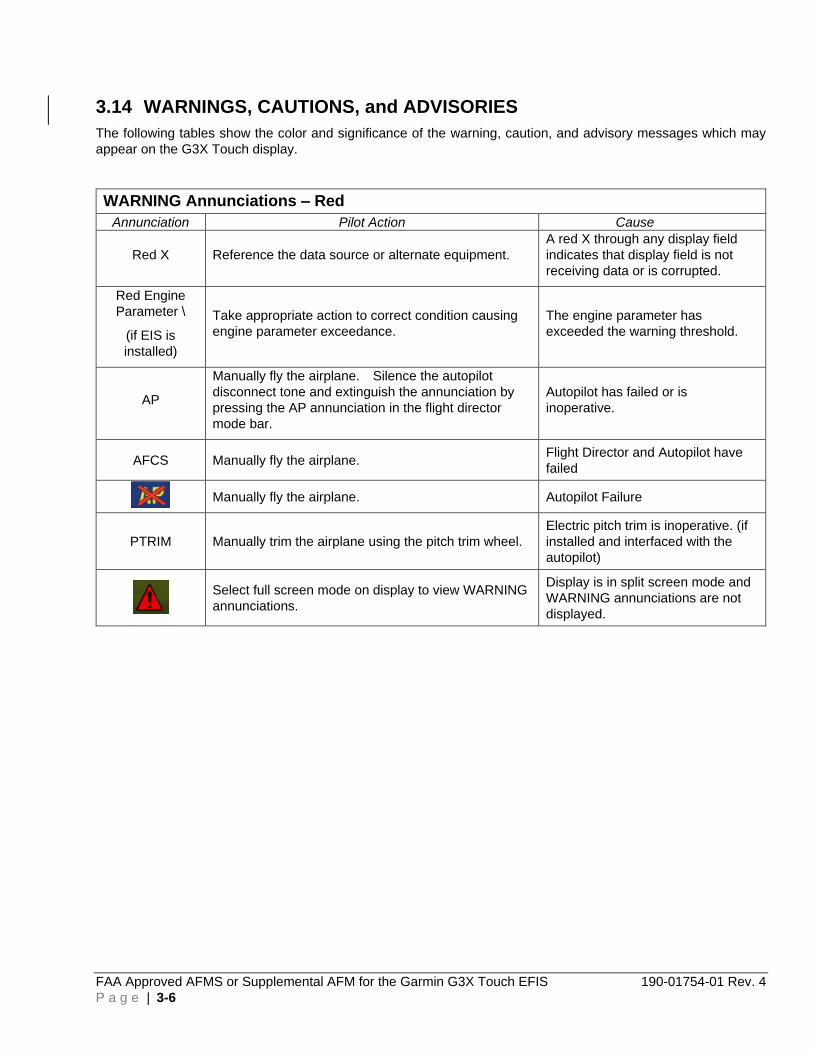
3.14 WARNINGS, CAUTIONS, and ADVISORIES
The following tables show the color and significance of the warning, caution, and advisory messages which may
appear on the G3X Touch display.
WARNING Annunciations – Red
Annunciation Pilot Action Cause
Red X Reference the data source or alternate equipment.
A red X through any display field
indicates that display field is not
receiving data or is corrupted.
Red Engine
Parameter \
(if EIS is
installed)
Take appropriate action to correct condition causing
engine parameter exceedance.
The engine parameter has
exceeded the warning threshold.
AP
Manually fly the airplane. Silence the autopilot
disconnect tone and extinguish the annunciation by
pressing the AP annunciation in the flight director
mode bar.
Autopilot has failed or is
inoperative.
AFCS Manually fly the airplane. Flight Director and Autopilot have
failed
Manually fly the airplane. Autopilot Failure
PTRIM Manually trim the airplane using the pitch trim wheel.
Electric pitch trim is inoperative. (if
installed and interfaced with the
autopilot)
Select full screen mode on display to view WARNING
annunciations.
Display is in split screen mode and
WARNING annunciations are not
displayed.

190-01754-01 Rev. 4 FAA Approved AFMS or Supplemental AFM for the Garmin G3X Touch EFIS
P a g e | 3-7
CAUTION Annunciations – Amber
Annunciation Pilot Action Cause
AP Manually fly the airplane Pilot has disconnected the autopilot
YD NONE Yaw Damper has disconnected
↑ TRIM UP ↑ Move the elevator trim in the nose up direction
until the annunciation extinguishes.
The autopilot is holding excessive force due
to the aircraft being out of trim due to
changes in airspeed or power.
↓TRIM DOWN↓ Move the elevator trim in the nose down
direction until the annunciation extinguishes.
The autopilot is holding excessive force due
to the aircraft being out of trim due to
changes in airspeed or power.
MIN SPEED Add maximum available power. Autopilot
will lower aircraft nose to increase airspeed.
Airspeed is too slow, approaching stall
speed.
MAX SPEED Reduce power. Autopilot will raise aircraft
nose to reduce airspeed.
Airspeed is approaching maximum
airspeed limit.
HDG
(amber
background)
Use standby compass Displayed heading is outside of the internal
accuracy limits.
Select full screen mode on display to view
CAUTION annunciations.
Display is in split screen mode and
CAUTION annunciations are not displayed.
AHRS ALIGN –
Keep Wings
Level
Fly aircraft manually and crosscheck attitude
indication with standby attitude indicator and
other sources of attitude information. Limit
aircraft attitude to ±10º bank and ±5º pitch as
AHRS Aligns - OK to taxi.
Attitude and Heading Reference System is
aligning. AHRS may not align with
excessive pitch/bank angles.
AHRS ALIGN
Fly aircraft manually and crosscheck attitude
indication with standby attitude indicator and
other sources of attitude information
(airspeed, heading, altitude, etc.)
The AHRS monitors have detected a
possible AHRS malfunction or an error with
the attitude presentation. The AHRS is
attempting to realign itself. The autopilot
may automatically disconnect.
ATT MISCOMP Cross-check the flagged information against
other sources to identify erroneous
information.
Difference detected between the G3X
Touch attitude display and the G5 attitude
display.
AHRS FAIL
ATTITUDE FAIL
Use standby attitude source, or, if AHRS
REVERT message is also displayed, continue
to use the G3X Touch. Attitude will be from
the G5.
The GSU 25 AHRS has failed.
AHRS REVERT
Continue to use the G3X Touch. The GSU 25 AHRS has failed and attitude
from the G5 is being displayed on the G3X
Touch.
AIR MISCOMP
IAS MISCOMP
Cross-check the flagged information against
other sources to identify erroneous
information.
Difference detected between the G3X
Touch airspeed or altitude and the G5
airspeed or altitude.

FAA Approved AFMS or Supplemental AFM for the Garmin G3X Touch EFIS 190-01754-01 Rev. 4
P a g e | 3-8
CAUTION Annunciations – Amber
Annunciation Pilot Action Cause
ADC FAIL
Use standby airspeed and altimeter indicator,
or, if ADC REVERT message is also
displayed, continue to use the G3X Touch.
The GSU 25 air data computer has failed.
ADC REVERT
Continue to use the G3X Touch. The GSU 25 air data computer has failed
and air data from the G5 is being displayed
on the G3X Touch.
(Flashing)
MESSAGE
Press the flashing message annunciation to
view a new system message.
A new system message has annunciated.
Amber EIS
Parameter
Take appropriate action to correct condition
causing engine parameter exceedance.
The engine parameter has exceeded the
caution threshold.
GPSS
De-select GPSS on the G3X Touch and
select desired alternate autopilot lateral
mode.
The GPS Steering command to the
autopilot has been lost.
TRAFFIC
Visually acquire the traffic to see and avoid. The interfaced traffic system has
determined that nearby traffic may be a
threat to the aircraft.
TAWS N/A,
TAWS FAIL
Use vigilance, terrain depiction and TAWS
alerting is no longer provided.
Database errors or lack of required GPS
position.
ECS FAIL NONE The Electrical Control System has failed
(GAD 27 FAILED)
ADVISORY Annunciations – White
Annunciation Pilot Action Cause
NO COMP Cross check information between the G5 and
the PFD to determine which unit is in error.
The unit will not be able to perform the
miscompare monitor function.

190-01754-01 Rev. 4 FAA Approved AFMS or Supplemental AFM for the Garmin G3X Touch EFIS
P a g e | 4-1
4 NORMAL PROCEDURES
4.1 BEFORE STARTING ENGINE
Database Acknowledgement (PFD) -------------------------------------------------- Press “CONTINUE’ button
NOTE
The data link weather advisory and current database information are displayed during power-up including valid operating dates, cycle number, and database type. When this information has been reviewed for currency (to ensure that no databases have expired), the pilot is prompted to continue.
4.2 AFTER STARTING ENGINE
Avionics Master Switch -------------------------------------------------------------------------------------------------- ON
Database Acknowledgment (All other displays and NAV units) --------------- Press “CONTINUE” button
Flight Plan Source (FPL) -------------------------------------------------------------------- Select EXTERNAL GPS
1. Press MENU, MENU
2. Highlight Setup and Select
3. Highlight Navigation and Select
4. Select External GPS for IFR or VFR flight, or,
5. Select Internal for VFR only flight
6. Press and Hold BACK Button to return to normal PFD display
G3X Touch CDI source --------------- Touch the HSI display on the PFD. PFD Options window opens.
In the CDI Source window ------------------ Select GPS 1 or GPS 2 (if installed) for IFR or VFR flight, or,
Select GPS for VFR flight
Touch the HSI display on the PFD to return to normal PFD display
Enter a Flight Plan ------------------------------ For IFR or VFR Flight, into the External GPS Navigator, or,
For VFR flight only, into the PFD Internal Flight Plan
WARNING
Do not use the approach information provided by the VFR navigation database residing within the G3X Touch as a means of navigating any instrument approach. The G3X Touch VFR navigation database is limited to present only the waypoints for the final approach leg of a published procedure. These waypoints and associated course line are made available for monitoring purposes only.

FAA Approved AFMS or Supplemental AFM for the Garmin G3X Touch EFIS 190-01754-01 Rev. 4
P a g e | 4-2
Altimeters ------------------------------------------------------------------------------------------------------------------- Set (PFD and Standby Altimeter)
1. Touch the Barometric Pressure Display on the PFD.
2. Enter the desired pressure using the keypad and touch ENTER.
3. Verify Barometric setting on the Standby Altimeter matches the G3X Touch.
4.3 COM Radio Tuning (Optional)
The COM Frequency Box is composed of two fields; one active frequency is on the left side and the standby frequency is on the right. To tune the COM radio:
1. Touch STBY com display window
2. Enter the frequency using the keypad or dual concentric knob
3. Touch ENTER to enter the frequency in the STBY window, or,
4. Touch to transfer the entered frequency directly into the COM window.
To transfer STBY frequency to Active frequency:
1. Touch the Active COM frequency field
4.4 Lateral Navigation
Changing the Navigation Source
When an external navigator that supports both GPS and VOR/ILS capabilities (i.e., GTN or GNS Series) is selected, the external navigator’s CDI Key is used to switch the G3X Touch HSI between GPS and VOR/ILS navigation.
VOR
1. Tune a VOR station in the external navigator.
2. Navigation Source ------------------------------------------ Select VOR on the external navigator
3. G3X Touch CDI source --------------------------------------- Touch the HSI display on the PFD.
PFD Options window opens.
4. Select the external navigator from the CDI Source window (VOR 1 or 2).
5. Press and Hold BACK Button to return to normal PFD display.
6. Set the CDI to the desired course -------- Touch the Selected Course window on the PFD
7. Enter the desired VOR course, press ENTER
8. Establish Intercept Heading
9. Select autopilot modes for intercepting or tracking the selected course ----------------- VOR
will be displayed on the FD mode bar.

190-01754-01 Rev. 4 FAA Approved AFMS or Supplemental AFM for the Garmin G3X Touch EFIS
P a g e | 4-3
NOTE
VOR will be annunciated in WHITE if the mode is armed or in GREEN if VOR is the active lateral mode.
GPS DIRECT TO
1. Navigation Source ------------------------------------------ Select GPS on the external navigator
2. Select waypoint and execute the Direct-TO on the external navigator
3. G3X Touch CDI source --------------------------------------- Touch the HSI display on the PFD.
PFD Options window opens.
4. Select the external navigator from the CDI Source window (GPS).
5. Press and Hold BACK Button to return to normal PFD display.
GPS OBS
1. Navigation Source ------------------------------------------ Select GPS on the external navigator
2. Select waypoint and make it the active waypoint.
3. Set external navigator to OBS mode
4. G3X Touch CDI source --------------------------------------- Touch the HSI display on the PFD.
PFD Options window opens.
5. Select the external navigator from the CDI Source window (GPS 1 or 2).
6. Press and Hold BACK Button to return to normal PFD display.
7. Set the CDI to the desired course -------------------------- Touch the Selected Course (OBS)
window on the PFD.
8. Enter the desired GPS course, press ENTER
9. Establish Intercept Heading
10. Select autopilot modes for intercepting or tracking the selected course ----------------- GPS
will be displayed on the FD mode bar.
4.5 APPROACHES
ILS
1. Load the approach into the External navigator ----------------------------------Verify external navigator
tunes the proper frequency. Select it as the active frequency.
2. Navigation Source ----------------------------------------------------- Select LOC on the external navigator

FAA Approved AFMS or Supplemental AFM for the Garmin G3X Touch EFIS 190-01754-01 Rev. 4
P a g e | 4-4
3. Approach Minimums------------------------------------------------ Set the barometric minimums alert bug
• On the PFD, Touch the HSI.
• Touch the Highlight Minimums window.
• Enter Barometric Altitude Minimums and touch ENTER
4. G3X Touch CDI source ------------------------------------------------ Touch the HSI display on the PFD.
PFD Options window opens.
5. Select the external navigator from the CDI Source window (LOC 1 or 2).
6. Press and Hold BACK Button to return to normal PFD display.
If Flying Vectors-To-Final:
7. Activate Vectors-to-Final on the external navigator, verify CDI changes to LOC and slews to the inbound course,
OR,
• If using a VHF navigation receiver, set the CDI to the desired course --------- Touch the Selected Course window on the PFD.
• Enter the desired LOC course, press ENTER.
8. Establish Intercept Heading.
9. Verify ACTIVE and ARMED modes on the PFD FD mode bar if using the autopilot/FD.
10. Upon reaching the LOC course, turn inbound and follow the ILS course and vertical guidance.
11. Set Missed Approach Altitude ------------------------------------ Touch the Reference Altitude display.
Enter the missed approach altitude.
12. At Decision Altitude (DA), continue visually for a normal landing,
OR,
• Press GO AROUND button and fly the missed approach procedure.
If Flying Full Approach Including Transition:
ACTIVATE THE APPROACH on the External navigator, Or,
ACTIVATE a DIRECT TO the IAF on the External navigator.
1. Navigation Source ---------------------------------------------------- Select GPS on the external navigator
2. Select IAF waypoint and execute the Direct-TO on the external navigator
3. G3X Touch CDI source -------------------------------------------------- Touch the HSI display on the PFD.
PFD Options window opens.
4. Select the external navigator from the CDI Source window (GPS 1 or 2).

190-01754-01 Rev. 4 FAA Approved AFMS or Supplemental AFM for the Garmin G3X Touch EFIS
P a g e | 4-5
5. Press and Hold BACK Button to return to normal PFD display.
6. Verify ACTIVE and ARMED modes on the PFD FD mode bar if using the autopilot/FD.
NOTE
The airplane will navigate in GPS mode throughout the intermediate portion of the approach procedure. When the airplane is inbound towards the final approach course, the CDI will automatically switch from GPS navigation to LOC navigation.
7. Verify -------------------------------------------------------------- Course pointer slews to the front course.
8. Upon reaching the LOC course Turn inbound and follow the ILS course and vertical guidance.
9. Set Missed Approach Altitude ------------------------------------ Touch the Reference Altitude display.
Enter the missed approach altitude.
10. At Decision Altitude (DA), Continue visually for a normal landing,
OR,
• Press GO AROUND button and fly the missed approach procedure.
ILS GLIDE SLOPE INOPERATIVE
1. Load the approach into the External navigator ----------------------------------Verify external navigator
tunes the proper frequency. Select it as the active frequency.
2. Navigation Source ----------------------------------------------------- Select LOC on the external navigator
3. Approach Minimums----------------------------------------------- Set the barometric minimums alert bug:
• On the PFD, Touch the HSI.
• Touch the Highlight Minimums window.
• Enter Barometric Altitude Minimums and touch ENTER
4. G3X Touch CDI source ------------------------------------------------ Touch the HSI display on the PFD.
PFD Options window opens.
5. Select the external navigator from the CDI Source window (LOC 1 or 2).
6. Press and Hold BACK Button to return to normal PFD display.
If Flying Vectors-To-Final:
7. Activate Vectors-to-Final on the external navigator, Verify CDI changes to LOC and slews to the inbound course,
OR,
• If using a VHF navigation receiver, Set the CDI to the desired course -------- Touch the Selected Course window on the PFD.
• Enter the desired LOC course, press ENTER.

FAA Approved AFMS or Supplemental AFM for the Garmin G3X Touch EFIS 190-01754-01 Rev. 4
P a g e | 4-6
8. Establish Intercept Heading.
9. Verify ACTIVE and ARMED modes on the PFD FD mode bar if using the autopilot/FD.
10. Upon reaching the LOC course, turn inbound and follow the LOC course.
11. Set Minimum Descent Altitude (MDA) --------------------------- Touch the Reference Altitude display.
Enter the Minimum Descent Altitude.
12. At the Final Approach Fix (FAF), begin descent to an intermediate altitude or the Minimum Descent Altitude.
13. At the Minimum Descent Altitude, Set Missed Approach Altitude - Touch the Reference Altitude display. Enter the Missed Approach Altitude.
14. At Missed Approach Point, Continue visually for a normal landing,
OR
• Press GO AROUND button and fly the missed approach procedure.
If Flying Full Approach Including Transition:
ACTIVATE THE APPROACH on the External navigator, Or,
ACTIVATE a DIRECT TO the IAF on the External navigator.
7. Navigation Source ---------------------------------------------------- Select GPS on the external navigator
8. Select IAF waypoint and execute the Direct-TO on the external navigator
9. G3X Touch CDI source -------------------------------------------------- Touch the HSI display on the PFD.
PFD Options window opens.
10. Select the external navigator from the CDI Source window (GPS 1 or 2).
11. Press and Hold BACK Button to return to normal PFD display.
12. Verify ACTIVE and ARMED modes on the PFD FD mode bar if using the autopilot/FD.
NOTE
The airplane will navigate in GPS mode throughout the intermediate portion of the approach procedure. When the airplane is inbound towards the final approach course, the CDI will automatically switch from GPS navigation to LOC navigation.
13. Verify ----------------------------------------------------------------- Course pointer slews to the front course.
14. Upon reaching the LOC course, turn inbound and follow the LOC course.
15. Set Minimum Descent Altitude (MDA) --------------------------- Touch the Reference Altitude display.
Enter the Minimum Descent Altitude.
16. At the Final Approach Fix (FAF), begin descent to an intermediate altitude or the Minimum Descent Altitude.
17. At the Minimum Descent Altitude, Set Missed Approach Altitude - Touch the Reference Altitude display. Enter the Missed Approach Altitude.

190-01754-01 Rev. 4 FAA Approved AFMS or Supplemental AFM for the Garmin G3X Touch EFIS
P a g e | 4-7
18. At Missed Approach Point, Continue visually for a normal landing,
OR
• Press GO AROUND button and fly the missed approach procedure.
RNAV (GPS) OR RNAV (GNSS) – (LPV, LNAV/VNAV, or LNAV+V)
NOTE
Some RNAV (GPS) or (GNSS) approaches provide a vertical descent angle as an aid in flying a stabilized approach. These approaches are NOT considered Approaches with Vertical Guidance (APV). Approaches that are annunciated on the HSI as LNAV or LNAV+V are considered Non-precision Approaches (NPA) and are flown to an MDA even though vertical glidepath (GP) information may be provided. Approaches that are annunciated on the HSI as LP will not have vertical glidepath (GP) information provided.
1. Load the approach into the External navigator.
2. Navigation Source ---------------------------------------------------- Select GPS on the external navigator
3. Approach Minimums----------------------------------------------- Set the barometric minimums alert bug:
• On the PFD, Touch the HSI.
• Touch the Highlight Minimums window.
• Enter Barometric Altitude Minimums and touch ENTER
4. G3X Touch CDI source ------------------------------------------------ Touch the HSI display on the PFD.
PFD Options window opens.
5. Select the external navigator from the CDI Source window (GPS 1 or 2).
6. Press and Hold BACK Button to return to normal PFD display.
If Flying Vectors-To-Final:
7. Activate Vectors-to-Final on the external navigator ------- Verify CDI slews to the inbound course.
8. Establish Intercept Heading.
9. Verify ACTIVE and ARMED modes on the PFD FD mode bar if using the autopilot/FD.
10. Upon reaching the GPS course, turn inbound and follow the GPS course and GP vertical guidance.
11. Verify on the HSI the Navigation mode indicates the approach being flown, (LPV, LNAV/VNAV, or LNAV+V)
12. Set Missed Approach Altitude ------------------------------------ Touch the Reference Altitude display.
Enter the missed approach altitude.
13. At Decision Altitude (DA or MDA for an LNAV+V), Continue visually for a normal landing,
OR
• Press GO AROUND button and fly the missed approach procedure.

FAA Approved AFMS or Supplemental AFM for the Garmin G3X Touch EFIS 190-01754-01 Rev. 4
P a g e | 4-8
If Flying Full Approach Including Transition:
ACTIVATE THE APPROACH on the External navigator, Or,
ACTIVATE a DIRECT TO the IAF on the External navigator.
7. Navigation Source ---------------------------------------------------- Select GPS on the external navigator
8. Select IAF waypoint and execute the Direct-TO on the external navigator
9. G3X Touch CDI source -------------------------------------------------- Touch the HSI display on the PFD.
PFD Options window opens.
10. Select the external navigator from the CDI Source window (GPS 1 or 2).
11. Press and Hold BACK Button to return to normal PFD display.
12. Verify ACTIVE and ARMED modes on the PFD FD mode bar if using the autopilot/FD.
NOTE
The airplane will navigate in GPS mode throughout the intermediate portion of the approach procedure. When the airplane is inbound towards the final approach course, the CDI will automatically slew to the inbound course.
13. Verify ------------------------------------------------------------------ Course pointer slews to the front course
14. Upon reaching the GPS course, turn inbound and follow the GPS course and GP vertical guidance.
15. Verify on the HSI the Navigation mode indicates the approach being flown, (LPV, LNAV/VNAV, or LNAV+V)
16. Set Missed Approach Altitude ------------------------------------ Touch the Reference Altitude display.
Enter the missed approach altitude.
17. At Decision Altitude (DA or MDA for a LNAV+V), Continue visually for a normal landing,
OR
• Press GO AROUND button and fly the missed approach procedure.
RNAV (GPS) OR RNAV (GNSS) – (LNAV, LP)
NOTE
Some RNAV (GPS) or (GNSS) approaches provide a vertical descent angle as an aid in flying a stabilized approach. These approaches are NOT considered Approaches with Vertical Guidance (APV). Approaches that are annunciated on the HSI as LNAV or LNAV+V are flown to an MDA even though vertical glidepath (GP) information may be provided. Approaches that are annunciated on the HSI as LP will not have vertical glidepath (GP) information provided.

190-01754-01 Rev. 4 FAA Approved AFMS or Supplemental AFM for the Garmin G3X Touch EFIS
P a g e | 4-9
1. Load the approach into the External navigator.
2. Navigation Source ---------------------------------------------------- Select GPS on the external navigator
3. Approach Minimums----------------------------------------------- Set the barometric minimums alert bug:
• On the PFD, Touch the HSI.
• Touch the Highlight Minimums window.
• Enter Barometric Altitude Minimums and touch ENTER
4. G3X Touch CDI source ------------------------------------------------ Touch the HSI display on the PFD.
PFD Options window opens.
5. Select the external navigator from the CDI Source window (GPS 1 or 2).
6. Press and Hold BACK Button to return to normal PFD display.
If Flying Vectors-To-Final:
7. Activate Vectors-to-Final on the external navigator ------- Verify CDI slews to the inbound course.
8. Establish Intercept Heading.
9. Verify ACTIVE and ARMED modes on the PFD FD mode bar if using the autopilot/FD.
10. Upon reaching the GPS course, turn inbound and follow the GPS course.
11. Verify on the HSI the Navigation mode indicates the approach being flown, (LNAV or LP)
12. Set Minimum Descent Altitude (MDA) --------------------------- Touch the Reference Altitude display.
Enter the Minimum Descent Altitude.
13. At the Final Approach Fix (FAF), begin descent to an intermediate altitude or the Minimum Descent Altitude.
14. At the Minimum Descent Altitude, Set Missed Approach Altitude - Touch the Reference Altitude display. Enter the Missed Approach Altitude.
15. At Missed Approach Point, Continue visually for a normal landing,
OR
• Press GO AROUND button and fly the missed approach procedure.
If Flying Full Approach Including Transition:
ACTIVATE THE APPROACH on the External navigator, Or,
ACTIVATE a DIRECT TO the IAF on the External navigator.
7. Navigation Source ---------------------------------------------------- Select GPS on the external navigator
8. Select IAF waypoint and execute the Direct-TO on the external navigator
9. G3X Touch CDI source -------------------------------------------------- Touch the HSI display on the PFD.
PFD Options window opens.
10. Select the external navigator from the CDI Source window (GPS 1 or 2).
11. Press and Hold BACK Button to return to normal PFD display.
12. Verify ACTIVE and ARMED modes on the PFD FD mode bar if using the autopilot/FD.

FAA Approved AFMS or Supplemental AFM for the Garmin G3X Touch EFIS 190-01754-01 Rev. 4
P a g e | 4-10
NOTE
The airplane will navigate in GPS mode throughout the intermediate portion of the approach procedure. When the airplane is inbound towards the final approach course, the CDI will automatically slew to the inbound course.
13. Verify ------------------------------------------------------------------ Course pointer slews to the front course
14. Upon reaching the GPS course, turn inbound and follow the GPS course.
15. Verify on the HSI the Navigation mode indicates the approach being flown, (LNAV or LP)
16. Set Minimum Descent Altitude (MDA) --------------------------- Touch the Reference Altitude display.
Enter the Minimum Descent Altitude.
17. At the Final Approach Fix (FAF), begin descent to an intermediate altitude or the Minimum Descent Altitude.
18. At the Minimum Descent Altitude, Set Missed Approach Altitude - Touch the Reference Altitude display. Enter the Missed Approach Altitude.
19. At Missed Approach Point, Continue visually for a normal landing,
OR
• Press GO AROUND button and fly the missed approach procedure.
VOR APPROACH
1. Load the approach into the External navigator ----------------------------------Verify external navigator
tunes the proper frequency. Select it as the active frequency.
2. Navigation Source ---------------------------------------------------- Select GPS on the external navigator
3. Approach Minimums----------------------------------------------- Set the barometric minimums alert bug:
• On the PFD, Touch the HSI.
• Touch the Highlight Minimums window.
• Enter Barometric Altitude Minimums and touch ENTER
4. G3X Touch CDI source ------------------------------------------------ Touch the HSI display on the PFD.
PFD Options window opens.
5. Select the external navigator from the CDI Source window (GPS 1 or 2).
6. Press and Hold BACK Button to return to normal PFD display.
If Flying Vectors-To-Final:
7. Activate Vectors-to-Final on the external navigator, Verify CDI changes slews to the inbound course from the FAF to the runway.
8. Navigation Source --------------------------------------------------- Select VOR on the external navigator.
9. G3X Touch CDI source ------------------------------------------------ Touch the HSI display on the PFD.
PFD Options window opens.
10. Select the external navigator from the CDI Source window (VOR 1 or 2).
190-01754-01 Rev. 4 FAA Approved AFMS or Supplemental AFM for the Garmin G3X Touch EFIS
P a g e | 4-11
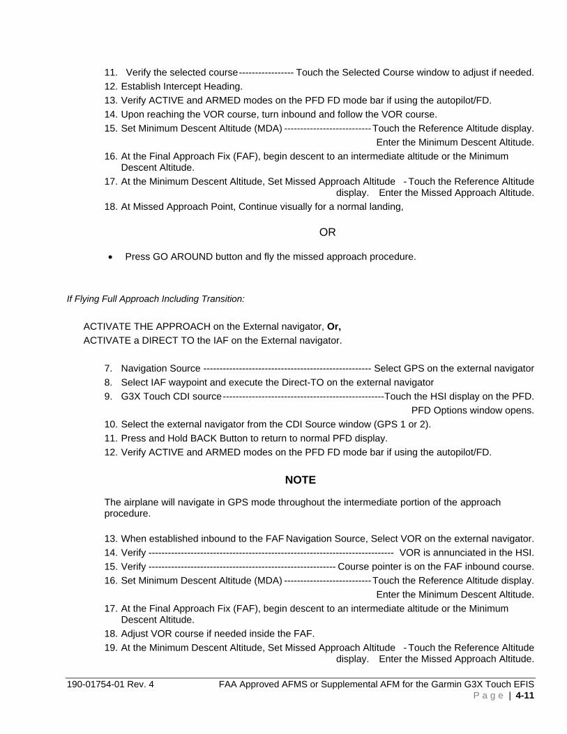
11. Verify the selected course ----------------- Touch the Selected Course window to adjust if needed.
12. Establish Intercept Heading.
13. Verify ACTIVE and ARMED modes on the PFD FD mode bar if using the autopilot/FD.
14. Upon reaching the VOR course, turn inbound and follow the VOR course.
15. Set Minimum Descent Altitude (MDA) --------------------------- Touch the Reference Altitude display.
Enter the Minimum Descent Altitude.
16. At the Final Approach Fix (FAF), begin descent to an intermediate altitude or the Minimum Descent Altitude.
17. At the Minimum Descent Altitude, Set Missed Approach Altitude - Touch the Reference Altitude display. Enter the Missed Approach Altitude.
18. At Missed Approach Point, Continue visually for a normal landing,
OR
• Press GO AROUND button and fly the missed approach procedure.
If Flying Full Approach Including Transition:
ACTIVATE THE APPROACH on the External navigator, Or,
ACTIVATE a DIRECT TO the IAF on the External navigator.
7. Navigation Source ---------------------------------------------------- Select GPS on the external navigator
8. Select IAF waypoint and execute the Direct-TO on the external navigator
9. G3X Touch CDI source -------------------------------------------------- Touch the HSI display on the PFD.
PFD Options window opens.
10. Select the external navigator from the CDI Source window (GPS 1 or 2).
11. Press and Hold BACK Button to return to normal PFD display.
12. Verify ACTIVE and ARMED modes on the PFD FD mode bar if using the autopilot/FD.
NOTE
The airplane will navigate in GPS mode throughout the intermediate portion of the approach procedure.
13. When established inbound to the FAF Navigation Source, Select VOR on the external navigator.
14. Verify ---------------------------------------------------------------------------- VOR is annunciated in the HSI.
15. Verify ---------------------------------------------------------- Course pointer is on the FAF inbound course.
16. Set Minimum Descent Altitude (MDA) --------------------------- Touch the Reference Altitude display.
Enter the Minimum Descent Altitude.
17. At the Final Approach Fix (FAF), begin descent to an intermediate altitude or the Minimum Descent Altitude.
18. Adjust VOR course if needed inside the FAF.
19. At the Minimum Descent Altitude, Set Missed Approach Altitude - Touch the Reference Altitude display. Enter the Missed Approach Altitude.

FAA Approved AFMS or Supplemental AFM for the Garmin G3X Touch EFIS 190-01754-01 Rev. 4
P a g e | 4-12
20. At Missed Approach Point, Continue visually for a normal landing,
OR
• Press GO AROUND button and fly the missed approach procedure.
BACK COURSE (BC)
1. Load the approach into the External navigator ----------------------------------Verify external navigator
tunes the proper frequency. Select it as the active frequency.
2. Navigation Source ---------------------------------------------------- Select GPS on the external navigator
3. Approach Minimums----------------------------------------------- Set the barometric minimums alert bug:
• On the PFD, Touch the HSI.
• Touch the Highlight Minimums window.
• Enter Barometric Altitude Minimums and touch ENTER
4. G3X Touch CDI source ------------------------------------------------ Touch the HSI display on the PFD.
PFD Options window opens.
5. Select the external navigator from the CDI Source window (GPS 1 or 2).
6. Press and Hold BACK Button to return to normal PFD display.
If Flying Vectors-To-Final:
7. Activate Vectors-to-Final on the external navigator, Verify CDI changes slews to the localizer front course.
8. Navigation Source ---------------------------------------------------- Select LOC on the external navigator.
9. G3X Touch CDI source ------------------------------------------------ Touch the HSI display on the PFD.
PFD Options window opens.
10. Select the external navigator from the CDI Source window (LOC 1 or 2).
11. Verify the selected front course ----------- Touch the Selected Course window to adjust if needed.
12. Establish Intercept Heading.
13. Verify ACTIVE and ARMED modes on the PFD FD mode bar if using the autopilot/FD.
14. Upon reaching the BC course, turn inbound and follow the BC course guidance.
15. Set Minimum Descent Altitude (MDA) --------------------------- Touch the Reference Altitude display.
Enter the Minimum Descent Altitude.
16. At the Final Approach Fix (FAF), begin descent to an intermediate altitude or the Minimum Descent Altitude.
17. At the Minimum Descent Altitude, Set Missed Approach Altitude - Touch the Reference Altitude display. Enter the Missed Approach Altitude.
18. At Missed Approach Point, Continue visually for a normal landing,
OR
• Press GO AROUND button and fly the missed approach procedure.

190-01754-01 Rev. 4 FAA Approved AFMS or Supplemental AFM for the Garmin G3X Touch EFIS
P a g e | 4-13
If Flying Full Approach Including Transition:
ACTIVATE THE APPROACH on the External navigator, Or,
ACTIVATE a DIRECT TO the IAF on the External navigator.
7. Navigation Source ---------------------------------------------------- Select GPS on the external navigator
8. Select IAF waypoint and execute the Direct-TO on the external navigator
9. G3X Touch CDI source -------------------------------------------------- Touch the HSI display on the PFD.
PFD Options window opens.
10. Select the external navigator from the CDI Source window (GPS 1 or 2).
11. Press and Hold BACK Button to return to normal PFD display.
12. Verify ACTIVE and ARMED modes on the PFD FD mode bar if using the autopilot/FD.
NOTE
The airplane will navigate in GPS mode throughout the intermediate portion of the approach procedure.
13. When established inbound to the FAF Navigation Source, Select LOC on the external navigator.
14. Verify ------------------------------------------------------------------------------ BC is annunciated in the HSI.
15. Verify --------------------------------------------------------------------- Course pointer is on the front course.
16. Set Minimum Descent Altitude (MDA) --------------------------- Touch the Reference Altitude display.
Enter the Minimum Descent Altitude.
17. At the Final Approach Fix (FAF), begin descent to an intermediate altitude or the Minimum Descent Altitude.
18. At the Minimum Descent Altitude, Set Missed Approach Altitude - Touch the Reference Altitude display. Enter the Missed Approach Altitude.
19. At Missed Approach Point, Continue visually for a normal landing,
OR
• Press GO AROUND button and fly the missed approach procedure.
GO AROUND (GA)
1. Control Wheel -------------------------------------------------------------------------------------- GRASP FIRMLY
2. GO AROUND button ------------------------------------------------------------------------------------------- PUSH
3. Rotate to Go Around attitude
4. Go Around -------------------------------------------------------------------------------------------------- EXECUTE
FAA Approved AFMS or Supplemental AFM for the Garmin G3X Touch EFIS 190-01754-01 Rev. 4
P a g e | 4-14
NOTE
If using a Garmin external navigator and an instrument approach is loaded, the HSI will automatically change to GPS course guidance, and the flight plan will automatically sequence onto the missed approach portion of the flight plan.
5. Verify the HSI changes to the GPS navigation.
6. Verify that leg sequencing has unsuspended. If not, unsuspend leg sequencing.
7. Fly Published Missed Approach Procedure, OR,
Fly ATC Assigned Missed Approach Heading
NOTE
The pilot is responsible for initial missed approach guidance in accordance with published procedure. The G3X Touch may not provide correct guidance until the airplane is established on a defined leg of the procedure.
8. Set Missed Approach Altitude ------------------------------------ Touch the Reference Altitude display.
Enter the Missed Approach Altitude.
4.6 Barometric Minimums Alert
A barometric minimums alert is provided in the G3X Touch to enhance the pilot’s awareness of approaching altitude minimums while flying an instrument approach procedure.
Setting the barometric minimums alert bug:
1. On the PFD, Touch the HSI.
2. Touch the Highlight Minimums window.
3. Enter Barometric Altitude Minimums and touch ENTER
CAUTION
If a new approach is loaded into an external IFR capable navigator, the pilot will need to update the Barometric Minimums Alert in the G3X Touch with the new approach’s altitude minimums.
4.7 TRANSPONDER Operation (Optional)
Entering Transponder Code
1. Touch the transponder data box.
2. Use the keypad to enter a code and touch ENTER.
IDENT
1. Touch IDENT, the green bar illuminates momentarily.

190-01754-01 Rev. 4 FAA Approved AFMS or Supplemental AFM for the Garmin G3X Touch EFIS
P a g e | 4-15
4.8 Disable Electronic Stability Protection (ESP)
(If Installed, GFC 500 Autopilot)
To disable ESP for flight training purposes:
1. Touch the FD mode status bar at the top of the PFD, Automatic Flight Control System window opens
2. Highlight and Select ESP. The green ESP status bar extinguishes. ESP is disabled.
3. Press and Hold the BACK button to close the Automatic Flight Control System window and return to PFD display.
4. To enable ESP, Highlight and Select ESP. The green ESP status bar illuminates. ESP is enabled.
5. Press and Hold the BACK button to close the Automatic Flight Control System window and return to PFD display.

FAA Approved AFMS or Supplemental AFM for the Garmin G3X Touch EFIS 190-01754-01 Rev. 4
P a g e | 4-16
This page intentionally left blank.

190-01754-01 Rev. 4 FAA Approved AFMS or Supplemental AFM for the Garmin G3X Touch EFIS
P a g e | 5-1
5 PERFORMANCE
No change.

FAA Approved AFMS or Supplemental AFM for the Garmin G3X Touch EFIS 190-01754-01 Rev. 4
P a g e | 5-2
This page intentionally left blank.

190-01754-01 Rev. 4 FAA Approved AFMS or Supplemental AFM for the Garmin G3X Touch EFIS
Page | 6-1
6 WEIGHT AND BALANCE
See current weight and balance data.

FAA Approved AFMS or Supplemental AFM for the Garmin G3X Touch EFIS 190-01754-01 Rev. 4
Page | 6-2
This page intentionally left blank.

190-01754-01 Rev. 4 FAA Approved AFMS or Supplemental AFM for the Garmin G3X Touch EFIS
P a g e | 7-1
7 SYSTEM DESCRIPTION
The G3X Touch System increases situational awareness by replacing the traditional instruments on
the panel with an easy-to-scan Primary Flight Display (PFD) that features a horizon, airspeed, attitude,
altitude, vertical speed, heading, and course deviation information.
7.1 Primary Flight Instruments
Attitude information is displayed over a virtual blue sky and synthetic ground with a white horizon line.
The Attitude Indicator displays the pitch (indicated by the Amber symbolic aircraft on the pitch scale),
roll, and slip/skid information.
The horizon line is part of the pitch scale. Pitch markings occur at 2.5˚ intervals through all pitch ranges.
The inverted white triangle indicates zero on the roll scale. Major tick marks at 30˚ and 60˚ and minor
tick marks at 10˚, 20˚, and 45˚ are shown to the left and right of the zero. Angle of bank is indicated by
the position of the pointer on the roll scale.
Slip/skid is indicated by the location of the ball.
Bezel Overview (GDU 46X)

FAA Approved AFMS or Supplemental AFM for the Garmin G3X Touch EFIS 190-01754-01 Rev. 4
P a g e | 7-2
Bezel Overview (GDU 470)
NRST Key
Press to display the Nearest Page for viewing the nearest airports,
intersections, NDBs, VORs, waypoints, frequencies, and airspaces
Direct-To Key
Press to activate the Direct-To function, enter a destination waypoint establish
a direct-to course to the selected destination
MENU Key
Press once to view the Page Menu Press twice to view the Main Menu
Press a third time to clear the Main Menu
enabled.
BACK Key
Press to return to the previous screen
Press and hold to return to the default MFD Page
The Standard Rate Turn Bank Angle Pointers are green pointers displayed on the roll scale that show
the bank angle corresponding to a standard rate turn.
Standard Rate Turn Bank Angle Pointers
The Turn Rate Indicator is located at the top of the HSI. Tick marks to the left and right of the displayed
heading denote standard turn rates (3 deg/sec). A magenta Turn Rate Trend Vector shows the current
turn rate. The end of the trend vector gives the heading predicted in 6 seconds, based on the present
turn rate. A standard-rate turn is shown on the indicator by the trend vector stopping at the standard
190-01754-01 Rev. 4 FAA Approved AFMS or Supplemental AFM for the Garmin G3X Touch EFIS
P a g e | 7-3
turn rate tick mark, corresponding to a predicted heading of 18˚ from the current heading. At rates
greater than 4 deg/sec, an arrowhead appears at the end of the magenta trend vector and the
prediction is no longer valid.
The Airspeed Indicator may be displayed as a vertical tape or a round dial. When the Airspeed
Indicator is displayed as a tape, it displays a range of 70 knots on a rolling number gauge using a
vertical tape. Numeric labels and major tick marks are shown at intervals of 10 knots. Minor tick
marks are at intervals of 5 knots. The current airspeed is displayed in the black pointer. The True
Airspeed (TAS) is displayed above the scale in white digits and the Ground Speed (GS) is displayed
below the scale in magenta digits.
The Altimeter may be displayed as a vertical tape or a round dial. When the Altimeter is displayed
as a tape, it displays 400 feet of barometric altitude values at a time on a rolling number gauge using
a moving tape. Numeric labels and major tick marks are shown at intervals of 100 feet. Minor tick
marks are at intervals of 20 feet. The current altitude is displayed in the black pointer. The barometric
pressure setting is displayed below the Altimeter in inches of mercury (in Hg) or hectopascals (hPa)
when metric units are selected.
The Selected Altitude is displayed above the Altimeter in the box indicated by a selection bug symbol.
A bug corresponding to this altitude is shown on the altimeter; if the Selected Altitude exceeds the
range shown on the tape, the bug appears at the corresponding edge of the tape.
The Altitude Alerting function provides the pilot with visual and aural alerts when approaching the
Selected Altitude. Whenever the Selected Altitude is changed, the Altitude Alerter is reset. The
following will occur when approaching the Selected Altitude:
• Passing within 1000 feet of the Selected Altitude, the Selected Altitude (shown above the
Altimeter) flashes for 5 seconds and an aural tone is generated.
• When the aircraft passes within 200 ft of the Selected Altitude, the Selected Altitude flashes
for 5 seconds and an aural tone is generated to indicate that the aircraft is approaching the
selected altitude.
• After reaching the Selected Altitude, if the pilot flies outside the deviation band (±200 Feet of
the Selected Altitude), the Selected Altitude changes to Amber text on a black background,
flashes for 5 seconds, and an aural tone is generated.
The Vertical Speed Indicator (VSI) may be displayed as a tape or an arc segment. The VSI displays
the aircraft vertical speed using a non-moving tape labeled at 500, 1000 and every 1000 fpm up to the
maximum with minor tick marks every 100 feet up to 1000 fpm. The current vertical speed is displayed
using a white arrow along the scale.
7.2 Vertical Deviation Indicators
The Vertical Deviation (Glideslope) Indicator (VDI) appears to the left of the altimeter whenever an ILS
frequency is tuned in the active NAV field of an external navigator. A green diamond acts as the VDI
Indicator. The green 'G' indicates an external glideslope source. If a localizer frequency is tuned and
there is no glideslope signal, “NO GS” is annunciated.

FAA Approved AFMS or Supplemental AFM for the Garmin G3X Touch EFIS 190-01754-01 Rev. 4
P a g e | 7-4
The Vertical Deviation (Glidepath) Indicator (VDI) also appears to the left of the altimeter during a GPS
approach. The glidepath is analogous to the glideslope for GPS approaches supporting WAAS vertical
guidance (LNAV+V, L/VNAV, LPV). The Glidepath Indicator appears on the G3X Touch as a magenta
diamond. The magenta 'G' indicates a GPS source. If the approach type downgrades past the final
approach fix (FAF), “NO GP” is annunciated.
An external navigation source is not required to receive VNAV indications. A magenta chevron (VNAV
Indicator) to the left of the altimeter on the Vertical Deviation Scale shows the VNAV profile, and a
magenta chevron (Required Vertical Speed Indicator (RVSI)) on the Vertical Speed Indicator indicates
the required vertical speed to reach the target altitude. The magenta 'V' indicates a VNAV profile is
active.
7.3 HSI Annunciations
Some or all HSI annunciations may appear in the four quadrants of the G3X Touch HSI depending on
the external navigator(s) configured.
Amber LOI – Loss of GPS integrity
Amber or Magenta VFR – An external GPS source is configured but there is not enough guidance
data for IFR use.
Amber REV – External navigation source failed. Reverted to internal VFR GPS for navigation.
Amber MSG – External navigation source has a pending message
Cyan INT – The pilot has elected to use the internal GPS navigation source instead of the external
GPS navigation source.
7.4 Course Deviation Indicator (CDI)
The HSI contains a Course Deviation Indicator (CDI), with a Course Pointer, To/From Indicator, and a
sliding deviation bar and scale. The course pointer is a single line arrow (GPS1, VOR1, and LOC1) or
a double line arrow (GPS2, VOR2, and LOC2) which points in the direction of the set course. The
To/From arrow rotates with the course pointer and is displayed when the active NAVAID is received.
The Course Deviation Indicator (CDI) moves left or right from the course pointer along a lateral
deviation scale to display aircraft position relative to the course. If the course deviation data is not
valid, the CDI is not displayed.
Another Lateral Deviation Scale and combination Course Deviation and To/From Indicator is located
below the slip/skid indicator.

190-01754-01 Rev. 4 FAA Approved AFMS or Supplemental AFM for the Garmin G3X Touch EFIS
P a g e | 7-5
Lateral Deviation Indication
The CDI can display two sources of navigation: GPS or NAV (VOR, localizer) depending on the
external navigator(s) configured. Color indicates the current navigation source: magenta (for GPS)
or green (for VOR and LOC). The full-scale limits for the CDI are defined by a GPS-derived distance
when coupled to GPS. When coupled to a VOR or localizer (LOC), the CDI has the same angular
limits as a mechanical CDI. If the CDI exceeds the maximum deviation on the scale (two dots) while
coupled to GPS, the crosstrack error (XTK) is displayed below the white aircraft symbol.
In addition to the flight instruments, the PFD also displays supplemental information, including the
Outside Air Temperature (OAT), wind data, User Timer, and G-Meter.
7.5 Display of PFD information on MFD
MFDs installed as part of the G3X touch system can display PFD information if manually selected by
the pilot, or will automatically do so if the installed PFD display fails. The display of PFD information
on an MFD is a duplication of the original PFD information and is not an independent compilation of
data from other sources.
7.6 Engine Indication System
The G3X Touch EIS displays engine, electrical, and other system parameters. Additional EIS
information can be viewed by selecting the Eng Page on the MFD.
Green bands on the instruments indicate normal ranges of operation; amber and red bands indicate
caution and warning, respectively. When unsafe operating conditions occur, the corresponding caution
readout will display solid amber and the warning readout will flash red. An aural alert is also issued
with a flashing red warning. If sensory data to an instrument becomes invalid or unavailable, a red
“X” is displayed across the instrument.
7.7 Communication / Navigation / Surveillance System
The Communication/Navigation/Surveillance (CNS) system includes the audio interface,
communication radios, navigation radios, and Mode S transponder. These functions can be accessed
from the boxes that make up the CNS Data Bar located at the top of the PFD and/or MFD.
CNS Data Bar
7.8 Remote Transponder Interface

FAA Approved AFMS or Supplemental AFM for the Garmin G3X Touch EFIS 190-01754-01 Rev. 4
P a g e | 7-6
The G3X Touch is capable of interfacing with several remote transponders providing Mode S
interrogation and reply capabilities. Transponder tuning for panel mount transponders is also
supported.
Ground Mode Ground Mode is normally selected automatically when the aircraft is on the ground. The transponder
powers up in the mode it was in when shut down. A green GND indication and transponder code
appear in the mode field of the Transponder Data Box. In Ground Mode, the transponder does not
allow Mode A and Mode C replies, but it does permit acquisition squitter and replies to discretely
addressed Mode S interrogations.
Standby Mode (Manual) In Standby, the transponder does not reply to interrogations, but new codes can be entered. When
Standby Mode is selected, a white STBY indication and transponder code appear in the mode field of
the Transponder Data Box.
ON Mode can be selected at any time. ON Mode generates Mode A and Mode S replies, but Mode C
altitude reporting is inhibited. In ON Mode, a green ON indication and transponder code appear in the
mode field of the Transponder Data Box.
Altitude Mode (Automatic or Manual) ALT Mode is automatically selected when the aircraft becomes airborne. When the aircraft is on the
ground, the transponder automatically selects and displays GND. ALT Mode may also be selected
manually.
If Altitude Mode is selected, a green ALT indication and transponder code appear in the mode field of
the Transponder Data Box, and all transponder replies requesting altitude information are provided
with pressure altitude information.
Reply Status When the transponder sends replies to interrogations, a green R indication appears momentarily in
the Transponder Data Box.
IDENT Function (GDU 460 and GDU 470) Touching IDENT sends a distinct identity indication to Air Traffic Control (ATC). The indication
distinguishes the identing transponder from all the others on the air traffic controller’s screen. After
touching IDENT the bar on the button turns green momentarily.
7.9 Minimum Altitude Display and Alerting
When enabled by the pilot, an altitude minimums bug will be displayed in cyan on the barometric
altitude tape.
Altitude minimums are accessed under the PFD Options Menu → Minimums sub menu and can be
set by touchscreen keypad or dual-concentric knob.

190-01754-01 Rev. 4 FAA Approved AFMS or Supplemental AFM for the Garmin G3X Touch EFIS
P a g e | 7-7
Both visual and aural altitude minimums alerts are provided. During a descent to minimums, the
minimums bug will change from cyan to white when the aircraft descends to within 100 ft of minimums.
An aural “Minimums, Minimums” alert will be triggered when the aircraft’s altitude descends through
minimums and the minimums bug will change to Amber. As the aircraft altitude climbs back above
minimums, the minimums bug will change to white 50 ft above minimums and cyan 150 ft above
minimums. Alerting is rearmed once the aircraft is 150 ft or more above the minimum’s altitude.
If a new approach is loaded into the external navigator, the Minimums Altitude display is not
automatically updated with the new approach minimums. The pilot must update the Minimums
Altitude Display with the MDA/DH for the approach loaded into the navigator.
7.10 AOA Probe (Optional)
The G3X Touch PFD will display angle of attack from the GAP 26 AOA probe if installed. The GSU
25D uses the pressure from the GAP 26 probe and the pitot/static pressures it already receives from
the existing aircraft pitot/static system to determine the aircraft’s angle of attack (AOA).
The AOA indications and warnings presented on the G3X system are for reference only and are not
intended as replacements for the aircraft’s original stall warning system. The AOA stall warning
margin and indications may not be the same at different flap settings, and are only supported for
positive G flight.
7.11 GAD 27 Wig Wag (Optional)
The GAD 27 module provides a feature that provides the ability to flash the Landing and Taxi lights of
the airplane in an alternating fashion, otherwise known as “Wig Wag”. Two 3-position switches
control this feature, one for the landing lights and one for the taxi lights:
• ON – Respective light is on
• FLASH – Respective light will flash
• OFF – Respective light is off
When both switches are in the FLASH position, the landing and taxi lights alternate off and on with
each other to produce the ‘Wig-Wag’ effect.
7.12 EIS Caution / Warning Lights
If the G3X EIS display is outside the pilot’s primary field of view and a PFD is not installed to provide
EIS annunciations, discreet Caution/Warning lights are installed. The lights are installed in the
primary field of view and are labeled ENGINE. Only a G3X EIS exceedance from a gauge on the
EIS Bar triggers the EIS Caution/Warning lights. EIS gauges that are not on the EIS Bar do not alert.