copy : OF - Defense Technical Information · PDF fileTECHNICAL DOCUMENTARY REPORT NO. ML-TDR...
88
ML-TDR-64- 173 IPart I -II HIGH TEMPERATURE PROTECTIVE f, COATINGS FOR GRAPHITE TECHNICAL DOCUMENTARY REPORT NO. ML-TDR-64-173, Part I June 1964 Air Force Materials Laboratory Research and Technology Division Air Force Systems Command Wright-Patterson Air Force Base, Ohio -copy_: OF HARD COPY DDC MICROFICHE $. : ': - " .. .. .SEP 1 1964 Project No. 7350, Task No. 73500Z DDC-IRA C (Prepared under Contract AI'33(657)-11253 by Union Carbide Corporation, Carbon Products Division, Parma, Ohio; J. M. Criscione, R. A. Mercuri, E. P. Schram, A. W. Smith, and H. F. Volk, Authors) • ReProduced h~ NATIONAL TECHNICAL INFORAACL S eOrtmN SERVIrE, 0V U e oment . I-,- - ' 1 51
Transcript of copy : OF - Defense Technical Information · PDF fileTECHNICAL DOCUMENTARY REPORT NO. ML-TDR...
ML-TDR-64- 173IPart I
-II
HIGH TEMPERATURE PROTECTIVE
f, COATINGS FOR GRAPHITE
TECHNICAL DOCUMENTARY REPORT NO. ML-TDR-64-173, Part IJune 1964
Air Force Materials LaboratoryResearch and Technology Division
Air Force Systems CommandWright-Patterson Air Force Base, Ohio
-copy_: OF
HARD COPY DDCMICROFICHE $.
: ': - " .. .. .SEP 1 1964
Project No. 7350, Task No. 73500Z DDC-IRA C
(Prepared under Contract AI'33(657)-11253 by Union Carbide Corporation,Carbon Products Division, Parma, Ohio;
J. M. Criscione, R. A. Mercuri, E. P. Schram,A. W. Smith, and H. F. Volk, Authors)
• ReProduced h~NATIONAL TECHNICALINFORAACLS eOrtmN SERVIrE,
0V U e oment .
I-,- - ' 1 51

i 0NOTICES
When Government drawings, specifications, or other data are used forany purpose other than in connection with a definitely related Government
- procurement operation, the United States Government thereby incurs noresponsibility nor any obligation whatsoever; ;nd the fact that the Go-ernmentmay have formulated, furnished, or in any way supplied the said drawings,specifications, or other data, is not to be regarded by implication or other-wise as in any manner licensing the holder or any other person or corporation,or conveying any rights or permission to manufacture, use, or sell anypatented invention that may in any way be related thereto.
Qualified requesters may obtain copies of this report from the DefenseDocumentation Center (DDC), (formerly ASTIA), Cameron Station, Bldg. 5,5010 Duke Street, Alexandria, Virginia 22314.
This report has been released to the Office of Technical Services,
rd U. S. Department of Commerce, Washington 25, D. C., for sale to the gen-eral public.
Copies of this report should not be returned to the Research and Tech-nology Division, Wright-Patterson Air Force Base, Ohio, unless return isrequired by security consider'ations, contractual obligations, or notice ona specific document.
FOREWORD
This is a Special Summary Report prepared by Union CarbideCorporation, Carbon Products Division, Research Laboratory, under UnitedStates Air Force Contract No. AF33(657)-11253, entitled "High Tempera-ture Protective Coatings for Graphite." This work is being administeredunder the direction of the Air Force Materials Laboratory, Research andTechnology Division with Mr. J. D. Latva and Captain W. Simmons asproject engineers.
* 'Work under this contract has been in progress since June 1, 1963, andis being carried out by the Carbon Products Division (formerly NationalCarbon Company) of Union Carbide Corporation, Parma, Ohio. The pro-gram is under the direction of J, C. Bowman, Director of Research, withE. Epremian, Assistant Director of Research, as Principal Investigator,and J. M. Criscione as Technical Coordinator.
The authors would like to express their thanks to J. L. Margrave,Rice University, for contributions to the vaporization studies.
U
S-

41
ABSTRACT
A review of previous work on protective coatings for graphite, a descrip-tion of several basic factors controlling the oxidation protection of graphite,and a review of existing information on the diffusion of oxygen and carbonthrough coating materials, the volatility, the chemical stability, and themechanical compatibility of coating materials is presented. It is concludedthat a considerable amount of researc" is needed to evaluate coating mate-rials for the protection of graphite from oxidation at temperatures of ZO00C
2e [. and higher.
This technical documentary report has been reviewed and is approved.
W. G. RAMKE*Chief, Ceramics and Graphite Branch
Air Force Materials LaboratoryResearch and Technology Division
iii
6*"

TABLE OF CONTENTS
I. INTRODUCTION.............................. . I
II. PREVIOUS WORK ON OXIDATION PROTECTIVECOATINGS FOR GRAPHITE. ........... 2
A. General Conclusions Regarding Previous Coating Work 2
B. Methods of Application and Testing ...... .... 2
C. Plating from Solution or Liquid Vehicle..... . . . 3
D. Chemical Reaction Deposition ....... .... 5
E. Hot Spraying ........... ...... . 12
F. Other Application Techniques. ...... . . . . 15
* I III. FACTORS CONTROLLING THE PROTECTION OF
GRAPHITE FROM OXIDATION ...... ........ 18
A. Diffusion through Crotective Coatings .. . . ... .. 18
B. Volatility of Coating Materials ...... ..... 33
g L C. Chemical Compatibility of Coating Materials . .... 40
D. Mechanical Compatibility of Coating Materialswith Graphite ........ .............. 52
IV. CONCLUSIONS ................. 65
U A. Previous Work on Oxidation Protective Coatings
for Graphite ......... ........ . 65
B. Diffusion through Protective Coatings ... ...... 65
C. Volatility of Coating Materials ...... . . . . 65
D. Chemical Compatibility ....... .... . 66
E. Mechanical Compatibility.. . ......... 66
iv

ILLUSTRATIONS
FIGURE PAGE
1. Factors Controlling the Ox-dation Protection of Graphite 18
2. Oxidation of the Platinum Group Metals(117) 41
3. Tensile Strength-to-Weight Ratios vs. Temperaturefor High Temperature Mate.,ials 54
4. Mean Coefficient of Thermal Expansion of Graphite vs.Temperature (Optical Dilatometer Method) 55
5. Linear Thermal Expansion Coefficients for Various0 Material Classes in the 250 to 1000°C Range 59
6. Linear Thermal Expansion of Various Oxides 59
7. Linear Thermal Expansion of Various Carbides 60
7. Linear Thermal Expansion of Various Borides 60
9. Linear Thermal Expansion of Various Metals 61
10. General Bend-Strength Levels for Various Material Classes 61
11. Thermal Conductivity of Potential Coating Materials 62
O
v
SO
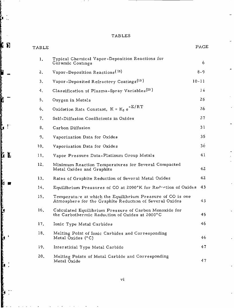
TABLES
TABLE PAGE
1. Typical Chemical Vapor-Deposition Reactions for
Ceramic Coatings 6
2. Vapor-Deposition Reactions( 15) 8-9
3. Vapor-Deposited Refractory Coatings(1s) 10-11
4. Classification of Plasma-Spray Variables(23) 14
5. Oxygen in Metals 25
6. Oxidation Rate Constant, K = K0 e E/RT ?6
7. Self-Diffusion Coefficients in Oxides 2,7
8. Carbon Diffusion 31
9. Vaporization Data for Oxides 35
1 0. Vaporization Data for Oxides 36
11. Vapor Pressure Data-Platinum Group Metals 41
12. Minimum Reaction Temperatures for Several CompactedMetal Oxides and Graphite 42
13. Rates of Graphite Reduction of Several Metal Oxides 42
14. Equilibrium Pressures of CO at 2000'K for Ree"-tion of Oxides 43
15. Temperatu.*e at which the Equilibrium Pressure of CO is oneAtmosphere for the Graphite Reduction of Several Oxides 43
16. Calculated Equilibrium Pressure of Carbon Monoxide for
the Carbothermic Reduction of Oxides at 2000'C 45
17. Ionic Type Metal Carbides 46
18. Melting Point of Ionic Carbides and CorrespondingMetal Oxides (°C) 46
19. Interstitial Type Metal Carbide 47
20. Melting Points of Metal Carbide and CorrespondingMetal Oxide 47
vi

TABLES (Cont'd)
TABLE PAGE
21. Potentiality of Carbides for Oxidation Resistance(14) 48
22. Metal Boride Stabilities 50
23. Melting Points of Promising Barrier Borides and theirCorresponding Oxides 51
24. Binary Silicon Compounds with Melting Points Greaterthan 2000'C 51
25. Melting Points of Metal Oxides Formed by the Oxidation ofHigh Melting Point Metal Silicides 52
26. Heats of Formation of Metal Silicides and Carbides 52
. 27. Factors for Calculation of Mean Coefficient of ThermalExpansion 55
28. Physical Properties of Manufactured Bulk Graphite 56
" 29. Liquidus Temperatures (°C' for Various Oxide Combinations C3
30. Minimum Solidus Temperatures for M-C Systems 63
31. Eutectic, Peritectic, and Compound Melting Temperatures 64
vii
S.

L
I. INTRODUCTION
The severe operational environment of missiles and space vehiclesimposes exacting requirements on E. ,:uctural components that must with-stand temperatures of approximatelN 20000C in oxidizing atmospheres.Graphite, because of its exceptional tability and strength at high tempera-tures, has been utilized extensively for components in missiles and highspeed aircraft. To make full use of these advantageous properties, however,graphite must be protected from air to prevent oxidation. Much effort hasbeen devoted to controlling the oxidation of graphite by the use of surfacecoatings, impregnants, and oxidation retardants. In the past, technicalapproaches to the problem have involved trial and error processes in whichvarious refractory coatings have been applied. The most satisfactory coat-ing for graphite, developed by this approach, is silicon carbide whichprotects graphite for substantial time periods to about 16500C. No system-atic effort to determine the principles leading to improved coating systemshas been put forth. Furthermore, no systematic effort to extend the opera-tional temperature range of the coatings for graphite has been put forth.
The protection of graphite from oxidizing atmospheres at high tempera-tures requires a barrier to retard or prevent corrosive chemical reactions.To perform this function adequately the protective layer must be adherent,of low volatility, chemically stable in the presence of moist and dry oxidizingatmospheres, and mechanically compatible with the graphite substrate.Furthermore, the protective coating must inhibit the diffusion of oxygen tothe substrate and the diffusion of carbon through th- coatings. These func-tions may be achieved by either a single layer or multilayer coating. The
number of possible single layer coating systems is limited because of thedifficulty in simultaneously obtaining oxidation protection, chemical stability,
and mechanical compatibility in such a simple system. Multilayer systemsprovide a means of separating chemically incompacible materials and ameans of simplifying the problems of achieving mechanical compatibility.
This report reviews previous work on protective coatings for graphite;it describes the basic factors controlling the operational behavior of oxida-tion protective coatings for graphite; and to this end, it reviews existingpertinent info2 mation on the diffusion of carbon and oxygen, the volatility,
the chemical stability and the mechanical compatibility of coating materials.
Manuscript released by authors June 1964 for publication as an RTDTechnical Documentary Report

II. PREVIOUS WORK ON OXIDATION PROTECTIVECOATINGS FOR GRAPHITE
A. General Conclusions Regarding Previous Coating Work
There is no coating available which will protect graphite from oxidationat a temperature of 2000*C. On the basis of past work, the best coating issiliconized silicon carbide which provides protection up to about 1700'C.
The method of testing coatings, places a large question mark after* almost every effort; the literature is filled with such phrases as .
affords considerable protection against oxidation." Little effort has beenmade towards developing test standards for coating materials. Too oftenthe previous studies on protective coatings for graphite failed to demon-strate whether the mechanism of failure was due to the method of applyingthe coating or due to some inherent pr-operty of the coating material.
*- It is evident from the following review of coating literature that moststudies have been narrowly directed; little has been accomplished in thenature of broad, comprehensive programs involving concentrated effortson kinetics, compatibility, and diffusivity studies on a single coating mate-rial (and families of material) with respect to carbon and oxygen. In thepast, emphasis has been placed on methods of applying coatings to graphiteand on qualitifive methods of testing the coating.
* LB. Methods of App.->ation and Testing
Numerous methods anC their combinations have been used to producecoating systems for graphite. Since a single coating material may beapplied by several different mcaods and may differ markedly in its chara-teristics depending on the metl- od of application, and since the emphasis ofprevious work on protective co.. ings for graphite has been on methods forcoating the substrate, this review of the past work will be based on coatingtechniques. Krier(I) has categorized these applications as follows:
(1) Plating from a solution or liquid vehicleElectroplating
_* AqueousFused salt
Electrophoretic deposition
(2) Chemical-reaction depositionVapor plating
* Pack diffusionExothermic reaction
[,.2

(3) Hot sprayingFlame sprayingPlasma sprayingDetonation or flame plating
(4) Other application techniques-Vacuum metallizing
Hot dippingSlurry dipping, painting, or trowelingImpregnationCladding
Processes employing several of these methods involve subsequent treat-ment steps such as hydrogen reduction, diffusion annealing, sintering anddensification a1nd infiltration of interconnecting pores. Each of these tech-niques has advantages and disadvantages, depending upon the coating material,the composition, size, and geometry of the component to be coated, and tleend use application. Frequently, the successful use of these methodsdepends heavily upon the experience of the people using them. Althoughgeneral underlying principles of the methods are known, there remainsmuch art in several of the methods.
The most widely used coating technique at the present time appears tobe the pack-diffusion (or cementation) method (SiC coatings). However, all
*of the techniques continue to be investigated, and several of the other methodshave exhibited excellent potential for producing coating systems.
The following review of coating literature indicates that most studieshave been narrow and directed; little has been accomplished iti the natureof broad, comprehensive programs involving concentrated efforts on com-patibility and diffusivity studies on a single coating material (or familiesof material) with respect to carbon and oxygen. Most coating programshave been concerned with methods of applying coatings; testing, if at all,
*. was generally accomplished by simple "on hand techniques" with a mini-mum of effort.
* _ The literature contains no indication that significant effort has beenexpended in developing test standards which will identify and evaluate thevarious desirable characteristics of these materials.
C. Plating from Solution or Liquid Vehicle
Electrodeposition techniques in general have the advantages of rela-tively low temperatures of operation, ease of control of coating thickness,ability to coat complex shapes, facility for applying multilayered coatings,and the ability to coat finished parts. Disadvantages include the multiplicityof operations and complexity of procedures, a tendency to produce porouscoatings, the difficulty in obtaiuing adequate protection at the point of
* electrical contact, and generally poor metal carbon bonding.
3
S

1 . Electroplating Aqueous
Standard acid bath electroplating techniques have been used to cladgraphite and carbon electrodes with copper and nickel(Z). Decreased con-tact resistance and low temperature protection against oxidation have beenaccomplished.
Various refractory compounds have been applied to graphite rocketnozzles from aqueous solutions similar to the standard chromium platingsolutionsp,4, 5). Refractory particles are suspended in the electrolyte toyield a deposit of a chromium matrix containing a fairly uniform dispersionof refractory. The cermets investigated were TaC, TaB, HfB2 , HfC, NbC,BN, SiN, SiC, ZrBz, ZrO2 , ZrB2 +MoSiz, and WB. The ZrBZ-Cr coatingperformed best on firing, although the coated nozzle burned out morequickly than the uncoated one (once the coating fails catastrophically thepieces do considerable damage to the throat).
: -' r2. Electroplating from Fused Salt
Tungsten, molybdenum, vanadium, zirconium, chromiam, and hafniumcolumbium, and tantalum have been applied to other metals and graphiteby the electrolysis of molten mixtures of the alkali metal fluorides andrefractory metal fluorides(6). Impervious tantalum 40 microinches thick
* Lhas been plated on copper. Coatings up to 0. 25-inch thick have been produced.
Considerable protection can be afforded molybdenum by a coating ofplatinum group metals deposited from a molten cyanide bath(7 , 8 ). A two-layer coating of Pt, Rh, or Ir on molybdenum may serve as a method ofprotecting graphite from oxidation.
U 3. Electrophoretic Deposition
This process involves colloidal particles which, when suspended in aliquid medium, migrate in an electric field and deposit on an electrode.Migration occurs because the particles are electrically charged, eitherpositively or negatively depending upon the composition of the system. Lamband Reid(9) have listed the following advantages for the method: (1) anelectrophoretic coating is denser than one applied by dipping or spraying,(2) the thickness of the coating can be closely controlled, (3) objects ofirregular shape acquire a coating that is fairly uniform in thickness (whenpoints and edges have been covered, the insulating effect of the coating onthese areas diverts the current to recessed areas), and (4) the rate ofdeposition is high because the depositing particles have a high ratio ofmass to charge. (Under typical operating conditions, an electrophoreticdeposit attains a thickness of I ril in about ten seconds, whereas anelectrodepcsit of the same thickness may require thirty to sixty minutes.Although a wide variety of materials can be deposited by electrophoresis,the deposits gent-rally have been found to be nonadherent and to re.uire sub-sequent processing, such as mechanical working, chemical reduction, andsintering.
4
6

The following materials have been deposited on graphite (and variousmetals) by electrophoresis(10): B, Dy, Au, Nb, Mo, W, Re, Nb 3Sn, ZrH2 ,ThC, UC, NpC, PuC, (ZrU)C, UWC 2 , UMoCz, UO,, Ta 2O5 , and bothW-UO 2 and vio-UOZ composites.
The coatings were sintered in place by heating in vacuum to -2000 ° C.Successful applications involving these coatings include: (a) protecting
A m reactive materials from gaseous corrosion, (b) coatings for bombardmenttargets for nuclear reaction studies, and (c) samples for the determina-tion of work functions.
Silicon, niobium, and Lantalum were deposited electrophoretically on agraphite substrate and subsequently carburized by a hydrocarbon techniqueat 1200°C0(1). Also, coatings of molybdenum disilicide were electro-phoretically deposited on graphite and subsequently sintered in argon at130000 (6 per cent nickel metal powder served as a cementing material).The carbide and silicide coatings were hard, adherent, and crack-free;however, all were characterized by a porosity of -25 per cent. Adherenceand thermal shock were tested by impinging an oxy-acetylene flame on thesamples for approximately thirty seconds (to reach 14000C). The MoSiz-Nicoated sample was not affected adversely; both the TaC + NbC coatingspalled from the substrate.
Electro-osmosis relates to the movement of a liquid through a porousstructure by an electrostatic force. Electrokinetic impregnation of graphiteresulted from electro-osmosis in a cell containing ZrH 2 dispersed inisopropano(2)' The ZrH2 was distribute throughout the sample with an
*average of 2. 1 per cent ZrH 2. On heating, the ZrH2 was converted to a*. ZrC. (Subsequent work indicates that pressure impregnation can be used
vth similar results.
D. Chemical Reaction Deposition
1. Vapor Plating
In the various modifications of the vapor-plating technique, also calledgas plating and vapor deposition, a volatile compound of the material to bedepo-sited is passed over the substrate which is heated to a temperature atwhich the compound is decomposed or reduced at the surface to form anadherent coating. The volatile compound can be reduced by hydrogenreduction, thermal decomposition, or displacement. Any material whichmeets the following requirements can be applied by vapor plating: (1) the
AQ material or its components must form a compound that can be vaporized ata relatively low temperature without appreciable decomposition; (2) thevolatile compound must be sufficiently unstable to be capable of decomposi-tion or chemical reaction at temperatures somewhat higher than itsvaporization temperature; and (3) the material must not have an appreci-able vapor pressure at the decomposition temperature.
The vapor-plating processes can be used to apply coatings of materialsat a temperature far beiow their melting points. Most of these processes
5

I can be carried out under either reduced or atmospheric pressure to givedeposits which are often purer than coatings obtainable by any other method.
Detailed thermodynamic and kinetic studies have been carried out foronly a few vapor-plating reactions; hence, the science of vapor plating, incontrast to the art, is in an early stage of development.
The vapor-?lating technique is not without its disadvantages; because ofnonuniform temperatures and gas flow; difficulties are encountered in coat-ing large or complex-shaped objects.
An excellent compilation of information on vapor-plating processes isthe book by Powell, Campbell, and Gonser(13).
Table 1 lists examples of reactions used to apply ceramic coatings( 14).
* Table 1. Typical Chemical Vapor-DepositionReactions for Ceramic Coatings
AlZCl 6 (g) + 3HzO(g) = A'Z0 3(s) + 6HCI(g)AlzC16(g) + 3CO2 (g) + 3H(g) = A1zO 3(s) + 6HCI(g) + 3CO(g)
BeClz(g) + HzO(g) = BeO(s) + 2HCl(g)
BeClz(g) + COz(g) + Hz(g) = BeO(s) + 2HCI(g) + CO(g)
MgIZ(g) + HFO(g) = MgO(s) + 2HI(g)
ZrCl 4 (g) + 2H2O(g) = ZrOz(s) + 4HCI(g)
2YCl 3 (g) + 3 H 2O(g) = Y2 0 3 (s) + 6 HCI(g)
2CrOClz(g) + H2O(g) + Hz(g) = CrZO 3 (s) + 4HCi(g)
CH 4 (g) = C(s) + ZHZ(g)
C21Hz(g) = ZC(s) + H.(g)
6
SQ
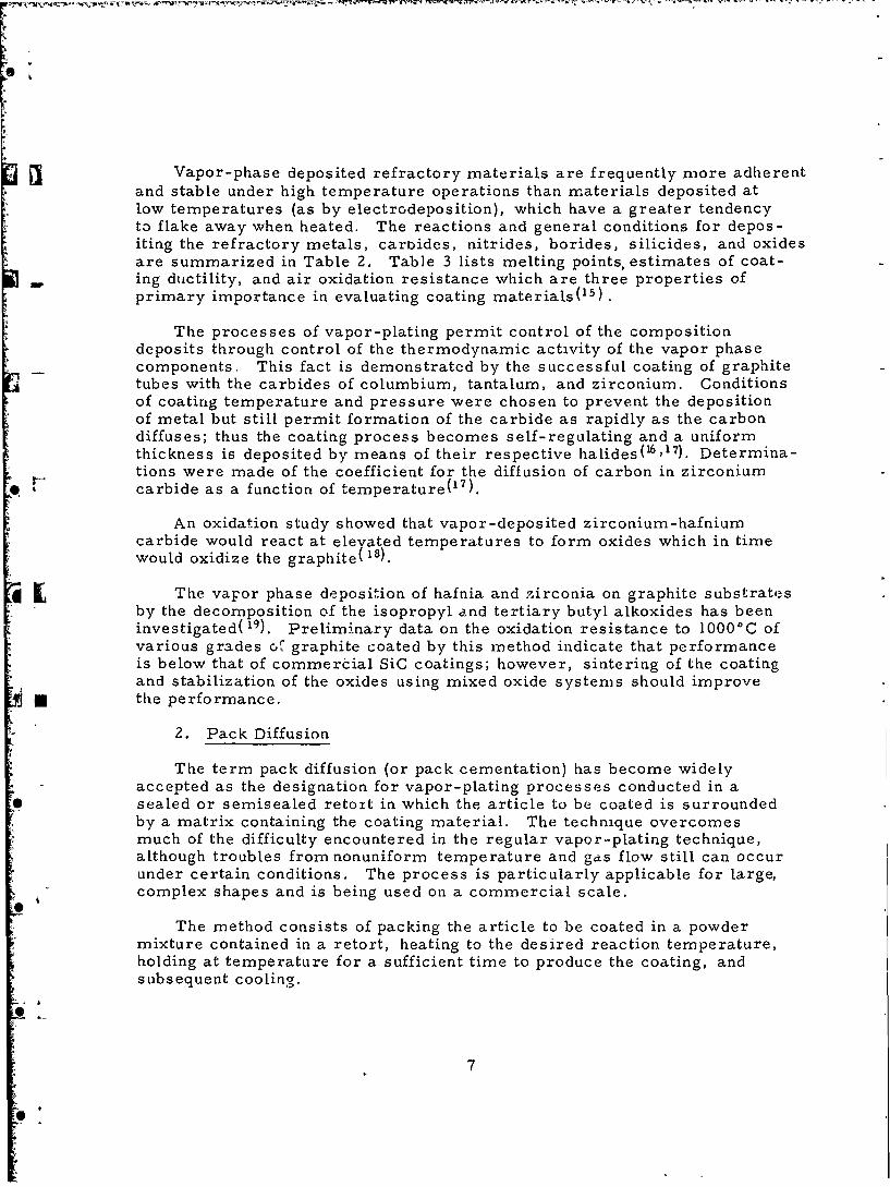
Vapor-phase deposited refractory materials are frequently more adherentand stable under high temperature operations than materials deposited atlow temperatures (as by electrodeposition), which have a greater tendencyto flake away when heated. The reactions and general conditions for depos-iting the refractory metals, carbides, nitrides, borides, silicides, and oxidesare summarized in Table 2. Table 3 lists melting points, estimates of coat-
-, ing ductility, and air oxidation resistance which are three properties ofprimary importance in evaluating coating materials(15).
The processes of vapor-plating permit control of the compositiondeposits through control of the thermodynamic activity of the vapor phasecomponents. This fact is demonstrated by the successful coating of graphitetubes with the carbides of columbium, tantalum, and zirconium. Conditionsof coating temperature and pressure were chosen to prevent the depositionof metal but still permit formation of the carbide as rapidly as the carbondiffuses; thus the coating process becomes self-regulating and a uniformthickness is deposited by means of their respective halides(6,17). Determina-tions were made of the coefficient for the diffusion of carbon in zirconium
F carbide as a function of temperature(17).
An oxidation study showed that vapor-deposited zirconium-hafniumcarbide would react at elevated temperatures to form oxides which in timewould oxidize the graphite( 18).
a L The vapor phase deposition of hafnia and ?irconia on graphite substratesby the decomposition of the isopropyl and tertiary butyl alkoxides has beeninvestigated( 19). Preliminary data on the oxidation resistance to 1000'C ofvarious grades of graphite coated by this method indicate that performanceis below that of commerdial SiC coatings; however, sintering of the coatingand stabilization of the oxides using mixed oxide systems should improve
* the performance.
2. Pack Diffusion
The term pack diffusion (or pack cementation) has become widelyaccepted as the designation for vapor-plating processes conducted in asealed or semisealed retort in which the article to be coated is surroundedby a matrix containing the coating material. The technique overcomesmuch of the difficulty encountered in the regular vapor-plating technique,although troubles from nonuniform temperature and gas flow still can occurunder certain conditions. The process is particularly applicable for large,complex shapes and is being used on a commercial scale.
The method consists of packing the article to be coated in a powdermixture contained in a retort, heating to the desired reaction temperature,holding at temperature for a sufficient time to produce the coating, andsubsequent cooling.
7

Table 2. Vapor-Dcposition ReactionsQN)
Reaction )cposition Total)eposit Typet) I)eposition Reaction Temp., 'C. (ins Pressure
(MI TAIA)
Titanium .................. I(a) Tillr4 + ll, -* 'i + M ir ..................... 900-1400 I atm.Titanium .................... 2(a) Tih14 - T i 4- 1 ............................ 1200- 1.100 VacuumZirconium ................... 1(a) ZrBr 4 + 112 --. Zr + IBr .................... 9)00-1400 1 atm.Zirconium ................... 2(a) Zr!4 -- Zr + I. ............................. 1300-1800 Vacuumlhafnium ................. 2(a) llf4--- lff + 12 ............................. ....... 100 VacuumThorium .................... 2(a) 'l'hI.4 T l + 12 . .......................... 1700 VacuumVanadium .................. 2(a) V1,-4 V + 12............................... 1100-1200 VacuumColumbiui .................. 1(a) (ICl + 112 - (b + IICI ............ ....... 600-1200 1 atm.'Tantalum ................... I(a) "I'aC& + 112 -- ''a + IICI ................... 600-1400 1 atm.Chronium ................... l(c) ('rC12 + MI+ 112 + IlCIJ -+ Cr + MI 2 . . . . . . . 900 1200 20 to 760 mm.
(M F, Ta. Mo, ecChromium ................... 2(a) Cr12 , C 1., + le] - Cr + 12 ............. 1000 1,100 10-1 to 760 mm.Chromium ................... 2(b) ('r(CO)6 + I± 2 -Pr Cr ± rsC, + CrIO, ......... 450-625 0 04 to 0.22 mam.Molybdenum .............. 1 I(a) MoCl + 112-. Mo + IICI .................. 500-1100 I attn.
S Molybdenum ................ 2(b) Mo(COa + 112* Mo 4- IC, IT, 01 ............. 450-750 <0.75 mim.Tungsten .................. 1(a) W(16 + 11 2 - W + lICI ..................... 500-1100 1 atm.Tungsten ................... 2(b) W(CO)4 4- 12---. W + IC, 11, 01 .............. 500 800? < 10 mm.?Uranium .................... 2(a) 1114-- U ± I .I .......................... 100 1800? VacuumRhenium .................... 2(a) 1 C('l:' 4- N21--. Re + C12 .................... 600- 1800 1 atm.Ruthenium .................. 2(b) INX, • y('O.- 1lu + X2 + CO .............. 600? 0.01--0.02 mam.Ihodium .................... 2(b) thX2 yCO - 1-11 Jhb + X, ± CO .............. 600? 0.01-0.02 mim.
[I IL Osmium ..................... 2(b) OsX 2 yCO- Os + X, + CO?............... 600? 0.01 -0.02 mm.
Iridium .................. 2(b) rX 2 • yCO -),- Ir + X2 + CO ................ 600? 0.01-0.02 mum.Platinum .................... 2(1) i'tC12 • 2CO -- >t + C2 + CO ............... 600 0.01-0.02 mn.
(X - CI, Br )r 1; y = 1, I, , or 2)Tantaium-columbium alloy .... 1(a) i'aCI + ('CCL -1- 112 -+Ta + Cb +- IICI ...... 600-1200 1 atin.Tantalum-titanium alloy ...... I(a) Talirs + 'Tilr 4 + !2-+Ta 4- Ti + IllIBr ....... 600-1200 1 attn.Tantalum-zirconium alloy ..... 1(a) TaBr, + ZrBr 4 -1- 112 -4 Ta + Zr + lIIBr ....... 600-1200 1 atm.
~~(CAntRDUs)
Carbon ...................... 2(a) CC14-> C + ('1, ............................. > 1000? VacuumBoron carbide .............. I(h) BCIx + 112 4- ('xlIy*--+ 1)(C 4 IICICII** ..... 1200-2000 1 attM.Silicon carbide ........ ..... (b) SiC 4 + I, t ('xtly --+ a SiC + ICI + [CIII... 1300-2000 1 atm.Silicon carbide ............. I(b) Si('14 + 112 4 CxIIy -+0 SiC + IICI + ICII]... 2000-2,100 1 atm.Titanium carbide ........... I(h) "ricI + , + CxIiy -+ TiC + IICI + ICII .... 1300-1700 1 atIn.Zirconium carbide ............ I(b) ZrCI4 + 112 4 ('xlly --+ ZrC + IICI + IC!!! .... 1700-2400 1 attn.Hafnium carbide ............. 1(b) IlfCI4 + 112 + Clly --+ IIfC + IICI - ICil... 2100-2500 1 atn.Vanadium carbide .......... I(b) . l 4- 112 4- CxlIy --+ VC + IICI + ICIII ..... 1500-2000 1 attn.Columbium carbide ......... I(c) 'b + 112 + CxlIy -+ CbC + 112 + [CIII ...... 1300 1 atn.
Tantalum carbide ............ I(c) Ta 4 -12 4- CxIly -+ TaC, Ta2C,Ta Cb + 1-12 + IC)] ...... 1300-2900 1 atm.
. Chromium carbide ........... 1() Cr - 112 + C 4 -* CrC2, Cr6C, + -12 + II.. 600-81)0 I atm.?Molybdenum carbide ........ I(e) Mo + 112 + Cl 4 -- + MoC + 124 ICIII ........ 700 1 attn.?Molybdenum carbide ......... 1(c) Mo + I1 + ('l14 -- Mo 2C + 112 + ICIII ....... 800 1 attn.?Molybdenum carbide ......... 2(b) Mo(COh 4- 1I,.- Mo2C + IC, 11, 01** ........ 300-800 0.1-3 mam.Tungsten carbide ............. 1(c) W + 3N2 4- I12 4- CxlIy -. WC + 112 4- N2
+ [CIII 1000-2200 1 atm.Tungsten carbide ............. I (c) W + 112 + (xlly -1 -a W2C + 112 + [CII] ...... 2100-2.400 1 attn.
* Tungsten carbide ............. 1) W - 112 4- (' Ily - + IVC :- 11, + CIII . 24.10-2550 1 attn.Tungsten carbide ............ 2(b) W((O) 4- 112 -* W2C 4- IC, I, 01 ............ 300-801? < 10 mm.?
8

*H
Table 2. Vapor-Deposition Rleactions (Continued)
Reaction Deposition TotalDeposit Type(' Deposition Reaction Temp., *C. Gas Pressure
(NrrniD~s)
- Boron nitride ................ l(b) BC13 + 3N, + 1112-- BN + IICI ............. 1200-2000 1 atm.Titanium nitride ............. I(b) TicIC 4+ 3N, + I11, --+,riN + I{CI ........... 1100-1700 1 atm.Zirconium nitride ............. 1(b) ZrCIi + 3N2 + III: -+ ZrN + IICI ............ 1100-2700 1 atm.Haifnium nitride .............. 1(b) ilfCI4 + 3N, + 1112--+ HfN + HCI ........... 1100-2700 1 atm.Vanadium nitride ............. 1(b) VCI4 + 3N, + 111,--+ VN + HCI ............. 1100-1600 1 atm.Columbium nitride ........... 1(c) Cb + N -- CbN ............................ 1000 1 atm.Tantalum nitride ............. I(c) Ta + N,: TaN ............................ 1000 1 atm.Tantalum carbide +
tantalum nitride ............ l(c) Ta + N, + CxHy -+ TaC + TaN ............. 1100-1200 1 atm.
(BORIDES)
Boron ................... 2(b) B211---. B + 112 ........... 400-600 1 atm.?Boron ................... (a) BC13 + H2--- B + IICI.................... 800-1600 1 atm.Aluminum boride ............. 1(b) AICI + BC!, + 11, Al boride + HCI ........ 1000 1 atm.Silicon boride .............. 1(b) SiC14 + BC,13 + I-- Si boride + I1CI ......... 1100-1300 1 atm.Titanium boride ............ I(b) TiCI, + BC13 + H2--Ti boride + IICI ........ 1000-1300 1 atm.Zirconium boride ............. 1(b) ZrCI + BC13 + 11 2 ) .Zr boride + 1CI ........ 1700-2500 1 atm.Hafnium boride ............ 1(b) HlfCl. + BC13 + 11-2- Hf boride + HCI ....... 100-2700 1 atm.Vanadium boride ............. 1(b) VC1l + BCI, + 11, -+ V boride + HCI ......... 900-1300 1 atm.Tantalum boride ............. l(a) Ta + BC13 + -- Ta boride + HCI .......... 1800-2000 1 atm.Chromium boride ............. 1(a) Cr + BC + 11,-. Cr boride + IC1 .......... 1200-1600 1 atm.Molybdenum boride .......... 1(a) Mo + BCI + H,- - Mo boride + IC ........ 1800-2000 1 atm.Tungsten boride .............. 1(a) W + BC13 + H1- W boride + 10 ........... 1800-2000 1 atm.
(SILIcIDEs)
Silicon ...................... 1(a) SiCI4 + H2--) SilICI ......................... 900-1400 1 atm.Ttanium silicide ............. 1(a) Ti + SiCh + H11-2 Ti silicide + HC .......... 1100-1500 1 atm.Zirconium silicide ............. 1(a) Zr + SiCI, + H2-) Zr silicide + HC .......... 1100-1500 1 atm.Columbium silicide ........... 1(a) Cb + SiCI4 + 1,-- Cb silicide + 1ICI ......... 1100-1800 1 atm.Tantalum silicide ........... 1 I(a) Ta + SiC. + H 2 )Ta silicide + 11C ......... 1100-1800 1 atm.C.,romiurn silicide ............ 1(a) Cr + SiCl4 + H,-). Cr silicide + IIC ......... 1100-1400 1 atm.Molybdenum silicide .......... 1(a) Mo + SiC!, + H 2 -- ) Mo silicides + HCI ....... 1100-1800 1 atm.
* Tungsten silicide ............. 1 (a) W + SiCIh + 112-+ W silicide + 11CI .......... 1100-1800 1 atm.Chromium-molybdenum silicide 1(a) Cr on Mo + SiCI4 + H, -+ Cr-Mo silicide + HCi 1100-1800 1 atm.
While no specific reactions of the type MCI. + SiCI, + H2 -+ MSi + 11C1 have been reported or carried out, thesilicides should be readily prepared by this method.
(OXwIES)
. Aluminum oxide ............ 1 l(b) AIC12 + C0 + 11,- AItO + CO + HC ...... 800-1000 1 atm.Silicon dioxide ............... 1 (b) SiC!, + C02 + 11-. SiO2 + CO + HC ....... 600-1000 1 atm.Silicon dioxide ............... 2(a) (C2H$)4SiO4[+ 112 or HC! -+ SiO2 + IC, H, 01 .... 600-900 1 atm.Zirconium oxide .............. 1(b) ZrCI4 + C0, + H 1-) ZrO2 + CO + 11C ....... 800-1000 1 atm.Chromic oxide ............... 2(a) IC6H702]Cr + CO--P Cr 2O, + [C, 11, 01 ....... 1000 1 atm.Aluminum oxide 4 zirconium
oxide ..................... 1(b) AICI, + ZrCI + C0, + H12--+ Ai,0s + ZrO2 +CO + HCI.. 800-1000 1 atm.
--*Indicates reaction occurs at high temperature.
.90

1 Table 3. Vapor-Deposited Refractory Coatings(15)
Depot I l n p o n OxidationDeposit I i. Ductilityl reistanceq
(Metale)
Tunpten 3410 2 4Rhenium 3170 I 4-5Tantaluwr 3000 1Osmium 2700 3 5Molybdenum 2620 3Ruthenium 2500 3 4-6Iridium 2454 2-3 4Columblum 2415 1 5Tntalum-oolumblum alloy 2300 1 5Illfnilum 1700-2230 1 3Ahodium loa 1 IChromium 1890 2 2-3Zirconium 1860 1 3Thorium 1830 1 3-4Platinum 1773 1 1Titanium 1725 1 3Vanadium 1700 1 4Uranium 1130 1 8Tantalum.titanium alloy - 1 3Tantalum.srconlum alloy - 4Ctromium-molybdenum alloy - - 4
(Carbides)
Tantalum carbide + hafnium carbide (4 TaC + I 0940 3 3111C)
Tantalum carbide + sircoulum carbide (4 TaC + 1 8930 3 3ZrC)
Hafnium carbide (111C) 3885 a 3Tantalum carbide (TaC) 3880 23 3Carbon 3530 3 4Zirconium carbide (ZrC) 3530 3 3Columblum carbide (CbC) 3500 2-3 3T "itanium carbide (TIC) 3135 3 3Tungten carbide (WC) d2865 3 5Tungptan carbide (WtC) d2855 3 5Vanadium carbide (VC) 2825 3 -Molybdenum carbide fMoC) d2690 3 aMolybdenum carbide (MotC) d2585 3 aBoron carbide (B3C. Bc) 2350-2500 3 3Silicon carbide (9iC) dl925 3 2Chromium carb do (CriCi) 1890 3 -
(Nitride)
Tantalum nitride (TaN) 3,85 3 aBoron nitride (WN) 30000 3 3Hafnium nitride (HfN) - $ -Zirconium nitride (ZrN) 2980 3 3Titanium nitride (TIN) d2945 3 3Vanadium nitride (VN) d2050 3 -Columblum nitride (CbN) d2060 1 5Tantalum cvrbide + tantalum nitride (TaC +TaN) 3305 2- 34
10

5) Table 3. Vapor-Deposited Refractory Coatings (Continued)
Deposlt tetinq oint, Ductility|j xidtin
(Borldes)
Hafnium bori d0e0SZirconium boide 2990 $ 3
Titanium boride - 8-3Tungsten boride 2920 $ 3-4Boron 23U0 8 3Tantalum boride 2000? 3 3Molybdenum bortde 2000? 3 3Aluminum borid - 3 3Silicon betide - 3 2-3Vanadium bortde 1300? $ 3-4Chromium borlde - 3 1-2
(Siliides)
Titanium sllicide 2000? 3 4Zirconium silicide 2000? 3 4Molybdenum slicide >1800 2 ITungsten silicide - - 1-2Columbium silicide - 2 4Tantalum silicido - 1-2 3Chromium silieide - 3 1-2Silicon 1420 3 3Chromium-molybdenum sllolde - - 1-2
(Oxides)
Zirconium oxide (ZO,, 2700 3 Ml)tAluminum oxide (AhsOa) 2050 3 (1) 1Aluminum oxide + zirconium oxide (AsO + ZrO,) 2000 3 (I)1Chromic oxide (CrOs) 1990 3 (I)1Silicon dioxide (SiO,) (glassy) 1713 3 1Silicon dioxide (SiO,) on aluminum oxide (Ai~s) - 3 (1)1
d-Decompoees before melting.. Under pressure.t The coating was too porous to prevent oxidation of the base, although not oxidized Itself.I The melting points of the borkde,sllicideand carbide coatings will,in praetice,vary widelysince the pure
compounds sre rarely obtained.I Ductility:I. Capable of being severely drawn, rolled, or otherwise worked without failure.2. Capable of withstanding slight deformation, or ocoslating of individually ductile crystals fragilely
bound together.3. Incapable of being worked; of glue-like brittleness.
Oxidation resistance:Classed according to the temperature ransein which thoratoof attack by air would cause severe ercelon orfailure of the coated specimen within a few hours. 1. Above 1700 C; 2. 1400-1700 C; 3. 1100-1400 C; 4. 800-1100 C; and 5. 500-800 C. The oxidation rate also depends upon other factors, such a coat thickness andrate of air flow past the specimen, which have not been taken into account here.
*The pack diffusion process, as generally used in protective coatingsfor graphite, takes place basically in three steps. First, coating materialis supplied to the substrate by vapor transport. Second, as the vapor con-centration increases in close proximity to the substrate material, a surfacereaction takes place between the coating metal and the substrate. Finally,atoms from the substrate are transferred by diffusion through the newlyformed surface to sustain the coating vapor substrate reaction. These proc-esses will continue either until the coating becomes too thick to allow suf-ficient substrate diffusion or until the coating material is depleted.
11

The major advantage of the pack-diffusion process is that a blend ofcoating material and finely divided inert filler completely surrounds thearticle to be coated, thereby eliminating the necessity for an apparatus tosupport or suspend the substrate during the coating operation and thuspermitting complete coating of complicated sl-apes in a single operation.
Graphite substrates to be SiC-coated by tLe pack-diffusion process are_. placed in a mixture of elemental silicon and an inert filler (such as TiC or
SiC) inside a graphite susceptor. The coating reaction is promoted byinductively heating the susceptor and pack to a temperature of 18000 to20000C for four to eight hours, after which the pack is cooled, disassem-bled, and the coated parts removed.
Oxidation tests(31 ) by electrical resistance heating indicated that graphitearticles coated by the pack-diffusion method were protected against oxidationfor thirty minutes at 15500C.
3. Exothermic Reaction
4 I Work has been in progress for some time to produce cermets bythermite-type reactions of the following categories:(-0)
(1) MOx +M' -- M'OX +M,
(2) SiOz + MOx +Al - A12 0 3 + MSix +MOx,
(3) C+ MO,. +Al - A1 2 0 3 + MC , and
(4) B 2 0 3 + MO x + Al - AlO 3 + MBx.
These methods have recently been considered as possibilities for producing*m coatings on refractory metals; however, work has not been sufficiently
extensive to evaluate their potential for this application(Z).
Nothing is known about the probability of exothermic reactions in pro-ducing coatings for graphite; they are presented as possibilities. The mostpromising aspects of this coating technique is its possible use in coating
4repair; a coating composition could be painted or sprayed on after which atorch could be used to produce the heat required to initiate the reaction(2).
E. Hot Sprayin
There are three processes ,;lassified under the hot-spraying technique:flame spraying, plasma spraying, and detonation or flame plating. In theseprocesses, the substrate is kept relatively cool, and the coating materials
12
II

in either the plastic or molten state are impacted against the substratewhere they quickly solidified. Interest in the hot-spraying techniques duringthe last few years has increased rapidly, particularly in plasma spraying,a process which involves the highest temperatures.
In general, the coatings produced by these techniques are line-of-sightcoatings, and as such, the methods have not been applicable to coating com-plex configurations which have deep narrow recesses or internally exposedsurfaces.
1. Flame Spraying
This process generally is conducted under oxidizing conditions and isnot so suitable for applying coatings to graphite substrates as are systemsinvolving reducing conditions. Several versions of flame spraying existwhich employ powders, rods, or wires which are formed into droplets inan oxyacetylene or oxyhydrogen flame.
The as-sprayed bond is almost entirely mechanical in nature(73 ),although, in some cases, a chemical bond is believed to exist. The sprayedparticles interlock with the mechanical projections and indentations in thesubstrate, the degree of roughness of which depends on the method used forsurface preparation. Most of the sprayed particles which strike the surfaceare sufficiently plastic to conform to the irregularities of the surface andhence interlock with Lhem. Almost all as-prepared flame-sprayed coatingshave some porosity; in some cases approaching 10 to 15 per cent of thecoated area(2 4 ) . Galli et al. (24)reviewed and critically examined the flamespraying process. Moore et al. (25) studied the mechanism of coating forma-tion, mechanism of bonding, and stresses in flame-sprayed coatings. Flame-sprayed coatings of MgZrO3 and A12 0 3 have been applied to graphite molds( 6 ).The MgZrO2 coated molds had - 2 1/z times the life of "wash" coated molds.
2. Plasma Spraying
The theoretical and applied aspects of plasma spraying have been andare continuing to be under intensive study, and the MAB report(2T) on plasma
*e phenomena gives an excellent review of the varied aspects involved and thelarge number of groups working on the broad subject.
Plasma spraying can be used to form a coating from any solid materialwhich will melt without decomposition. The extremely high temperaturesavailable under neutral or reducing atmospheres make the technique of
Sparticular interest where especially oxygen-sensitive materials are involved.Higher density and bond strength of the sprayed coatings have been teportedas other advantages(27) . Literature on operating procedures, equipment, andmaterials is available in abundance.
Plasma spraying is not a simple technique, and the results obtained ina sprayed coating can depend on many factors. Mash, Weare, and Walker( z8)presented the classification of process variables given in Table 4. Stetson
1'3
So

and Hauck(zq ) reported on plasma techniques for spraying toxic and oxidizablematerials.
Sudies on the effects of plasma spraying on the properties and stabilityof nonmetallic materials have been in progress(' 10).
- Table 4. Classification of Plasma-Spray Variables(23)
A. Plasma C. powder Feed D. Spraying Procedure
1. Power input 1. Type of powder feed system 1. Torch-to-work distance2. Type of arc gas Z. Rate of powder addition to 2. Traverse rate3. Flow of arc gas carrier gas 3. Angle of torch with work4. Plasma-torch geometry 3. Type of carrier gas 4. Cover gas
4. Flow of carrier gas 5. Spraying atmosphereB. Powder 5. An~le of powder entry into
plasma E. Substrate1. Compoaition 6. Location of nowder entry 1. Composion2. Physical properties port 2. Surface-preparation3. Method of manufacture method4. Powder size 3. Surface roughness5. Particle-size distribution 4. Temperature
As-sprayed zirconia (on graphite) exhibited fine cracks and was heavilystressed(3 0). However, when athick dense layer of ZrBZ was deposited ongraphite and then subjected to a high temperature oxidizing environment for
* mone minute in a plasma stream of 80 per cent nitrogen and 20 per cent oxygencapable of reaching 36000C, the coating was converted to an adherent non-spalling layer of zirconia which provided "good" protection. The surfacetemperature of the test specimen could not be measured because of emittanceof gaseous boron compounds. In identical tests, involving coatings of ZrN,ZrC, CrO,, HfO2 , HfC, TiN, and TaO, only CrO 3 and HfC gave "good"protection. The surface temperatures for these tests were reported to be inthe 1650' to 2750°C range.
Titanium diboride was applied to ATJ graphite via plasma spraying tech-niques(31). A 0. 012 inch coating protected graphite for six or seven fiveminute cycles at 142000 in air. Above 1640°C, the coating failed quite rapidly.
Heat treated SiB 6 coatings were penetrated in three minutes at 17500Cin air, whereas SiC (pack-diffusion) coated samples lasted for ten minutes.Magnesium zirconate coatings protect graphite for less than thirty minutesat 14000C and for no more than a few minutes at 1800°C(331
* ,_ Calcium and magnesium zirconate coatings were applied by plasmaspraying to graphite substrates which had been previously coated with tung-sten. Oxidation test data show that the zirconates of magnesium and calcium
14
6S

afford good protection at ~1500°C and are useful at higher temperatures forsingle exposure, short-time applications(31).
3. Detonation or Flame Plating(32 )
The Union Carbide, Linde Division's "flame plating" apparatus is one inwhich a coating powder and a carrier gas are fed into an oxygen-acetylenegun chamber which detonates about four times a second. The detonationfront travels at 9600 ft/sec at 8000'F and at a pressure of 47 atmospheres;it impacts the coating particles against the substrate at about 2400 ft/sec.
*The rate of deposition is ~1/ 4 mil over a one-inch circular area for eachdetonation or -1 mil per second. The substrate temperature is maintainedbelow 400C.F(33).
This method of ,oating is generally used with less easily abraded sub-strates than graphite; more satisfactory coatings can be applied using plasmaspray techniques.
F. Other Application Techniques
This category of coating application, which includes vacuum metallizing,'- dipping, painting and sintering, slip casting, hand troweling, and cladding,
should not be considered as a "catchall" category which contains all methodsof minor importance. Several of these techniques, or modified versions ofthem, have been found to produce good coating systems.
1. Vacuum Metallizi,.,
This method is widely used to apply thin films, generally for decorativeand optical purposes, to substrates held at low temperatures; in general,poor adherence occurs and the coatings are usually stressed and porous. Themethod may be used to strike a base coat on graphite which could subsequentlybe electroplated and sintered to produce a dense, adherent coating.
Investigations included the evaporation of SiO onto a substrate with bub-sequent heating in air to convert to SiO 2 (34 ). These coatings failed at 1200*C.
A substantial improvement in technique was made in vacuum metallizingsilicon onto graphite by heating the graphite target.
Coatings which diffeied in thickness by a factor of 10 (0. 001 to 0.010inchwere oxidized at several tcmperatures 1 ) In all tests below 1700'C, thecoatings were protective for the duration of the tests (thirty minutes). Oxida-tion tests by electrical resistance heating showed that graphite articles coatedwith SiC-Si were unattacked at 1700°C during five-hour exposures. Several
- specimens exhibited similar protection at 1750' and 1800'C; however, someshowed a tendency toward rapid oxidation bordering upon combustion.
2. Hot Dipping
Applying coatings by the dip technique sometimes has the disadvantage ofpoor uniformity, poor coverage on complex shapes and corners, and inclu-sions in the coating which occur during dipping. The only high temperatureuse based on this technique is the Naval Research Laboratory's zinc coatingfor columbium; however, flame-spraying coatings are frequently given a diptreatment in molten aluminum or glass to seal the pores in the deposit(32)
15

3. Slurry Dipping, Painting, or Troweling
Applying coatings by the slurry method consists of blending the coatingcomposition in the powder form, suspending the powders in a liquid carrierto make a slurry, and painting, dipping or spraying the coating slurry onthe substrate. After air drying the coating is diffused into the substrate byheating in an inert atmosphere or vacuum.
White(3 5) coated graphite with a silicon paint and reaction sintered thecoating in vacuum at 14000C. The coated samples were tested at 10000Cfor twenty-four hours in air; the core graphite was completely oxidized.
Borides and carbides with melting points of 2300°C and higher wereapplied to graphite with a slurry technique and then heat treated in agraphite tube furnace under argon( 6 ). With all the borides used (TiB2 ,ZrB2 , TaB2 , and WB), it was found that with increasing temperature thecoatings sintered, melted with retention of position, and then flowed. Theideal coating was formed at the melting point (usually 6000C less than themelting point of the borides). Evidence indicates that the coatings were
SI-formed through the melting of boride-carbon and carbide-metal eutectics.Carbide coatings were formed in situ from the metals (Ti, Zr, Nb, Ta, W).Evaluation tests demonstrated that Zr-containing coatings "afforded con-siderable protection against oxidation to the underlying graphite in anoxidizing flame at temperatures of 21000 to 22000C(36)" However, thisresult is due to the ZrOz layer which can be disrupted quite easily. Oneinteresting observation was that WzC (or possible WC) has unusually slowoxidation ratesin the temperature range of 18000 to 2200'C; however, itsoxides offer no protection at these temperatures.
Some comments on the long term oxidation resistance of silicide-coated*graphite, including some thermochemical data, were published by
J. Chown and A. E. S. White(3 7). They concluded that the upper limit of usefor SiC ware is set by the reaction between SiC and Si0 2 at 16500C. In thecase of MoSi2 , de-wetting of the silica film or increase in oxygen diffusionat the "melting point" of silica appear to be the causes of failure.
A coating of ZrB Z and 5 to 15 per cent MoSi z was applied to graphite,, -SiC, and several other refractory materials(38 ). Oxidation for fifteen
minutes at 19500C indicates that a silicon carbide sample, with a 10 to 20 mil*coating was completely protected.
4. Impregnation
Impregnation techniques such as pressure and ultrasonic vibration were*: used to apply a penetrating layer of ZrH2 in graphite which would eventually
be used as a base for further coatings(12). The weight per cent of ZrH2 was2. 6 and 1. 9 at 1 and 4 mm depth respectively when applied to AGW graphitefrom an alcohol suspension by means of the pressure technique. Althoughno further information is given, it may be assumed that subsequent to impreg-
- "nation the samples were heated to form ZrC in situ.
16
5. Cladding
Cladding techniques have been used for bonding oxidation-resistant alloysto refractory metal substrates. It is an ideal method for applying a con-tinuous chemically and metallurgically sound coating of metal to a substrate.The limitations of cladding are: the simple shape requirement, the metal-lurgical problems of diffusion, bond strengths, the formation of low meltingphases or brittle intermetallics, and the problem of protecting corners,ends, and edges.
For the protection of graphite, roll and forge cladding techniques donot show the promise which is demonstrated by a recently developed method
- involving gas pressure bonding of the cladding layer to a base material(39 ).
There are no reported studies concerning the cladding of graphite withoxidation resistant materiils, although the method has obvious possibilities.
6'
,. 17
.g

* III. FACTORS CONTROLLING THE PROTECTIONOF GRAPHITE FROM OXIDATION
It has been pointed out that previous work on protective coatings forgraphite has been confined mainly to methods of applying coatings to thesubstrate and somewhat qualitative testing which often gave inconclusiveresults. Little effort has been expended to determine the mechanism of Sfailure or to adequately evaluate the coating materials as an oxidation prohib-iting layer. In emphasizing methods of applying coatings and their testing,investigators have overlooked many important factors involved in protection-f graphite from oxidation.
Certain problems inherent in the development of a successful oxidation- •
resistant coating for graphite are described in Figure 1. Considering the
substrate and environment, main consideration should be given to the dif-fusion of oxygen and carbon through the coating material to evaluate properlytheir potential as barriers to oxidation. To function adequately as a protective
OXYGEN IN VOLATILITY
-COATING
CARBON CHEMICAL AND -SUBSTRATEOUT MECHANICAL
COMPATIBILITY (GRAPHITE.
Figure 1. Factors Controlling the OxidationProtection of Graphite.
layer, the volatility of the coatings must be low, particularly in environ-ments of reduced pressures and high temperatures. The adherence of the 0coatin; and its behavior as a protective layer will also be governed by itschemical stability with respect to oxygen and carbon and its m chanicalcompatibility. A review of existing information pertinent to these factorscontrolling the operational behavior of an oxidation protective coating hasbeen carried out to determine potential coating systems andto determinewhat further information is required to reach a level of understanding •whereby coatings can be developed for the protection of graphite from hightemperature oxidation.
A. Diffusion through Protective CoatingsThe protection of graphite from oxygen at high temperatures requires -
a single or multilayer coating which has low permeabilities to oxygpr, and
18

carbon. The permeability of a coating may be limited by the rate ofreactions which take place at either surface of the coating as well as by dif-fusion through the coating(40). Since the rate of diffusion through a coatingdepends on the diffusivity and on the concentration of the diffusing substance,surface reactions should be considered because they determine the concen-tration of the diffusing substance in the coating. To evaluate prospectivecoating materials, the permeabilities should be determined under conditionswhich occur in an actual coating. The diffusion of oxygen or carbon in pos-sible coating materials must be evaluated with this fact in mind.
The following section consists of a presentation of the mathematics andmechanisms of diffusion, followed by a critical discussion of the literaturepertinent to the diffusion of oxygen and carbon through various classes ofmaterials. An evaluation of possible coating materials and an indication ofstudies needed to fill L,!e gaps in our present knoxledge concludes the section.
1. Mathematics of Diffusion through Membranes
The steady-state rate of mass transport through a membrane is given inEquation 1 by Fick's first law,
dx
whereP is the pErmeability,D is the diffusivity, anddcd-is the concentration gradient.
Assuming that the diffusivity is independent of concentration, Equation 1 canbe written as
~C P C zPD (2)
where C, and CZ are the concentrations just within the two surfaces, and I isthe thickncss of the membrane. If the rate determining step is diffusionwithin the solid and not transport across the boundaries, C, and C? are theconcentrations in equilibrium with each external phase. A coating which isused to protect carbon against oxidation will have one surface against a highlyoxidizing pbase and the other against a highly reducing phase.
When the conditions under which diffusion occurs are suddenly applied,the steady-state permeation does not take place instantly. The build-up ofthe diffusing :ubstance passing through a membrane is obtained by solvingFick's second law,
dc D (3)-t TdX-z-
19

Barrer(41) gives a solution for the case where
C = C, at x = 0 for all t,C = Cz at x = I for all t, andC = Coat 0< x < £ at t = 0.
This solution is:
Co Dn2 'rr t 0 D(Zm+l )Tr 2 t(dc) C2-Cl 2 (Czcos n i -C)e + 4 CO e (4)
= m=0
If the total amount of matter diffused through the membrane is plottedagainst time, after an initial period a straight line is obtained. Extrapol-ating this line back to zero gives an "induction time" L,
L =- 2 - L C 2 + (5)C2-Cl 6D 3D 2Dj
For the case where Co = 0 and Ci<< Cz,!.2
L (6)
Thus, by measuring the time dependence of the permeation not only thepermeability but also the diffusivity and the concentration of the diffusingmaterial may be obtained. This analysis also shows that although a givencoating may have too high a permeability for extended use, its diffusivitymay be low enough to give protection for an adequate length of time.
Two other cases should be treated since they are pertinent to the coat-ing problem and the method whereby diffusion is measured. One caseinvolving the condition wherein the thickness is not constant as in the oxida-tion of a metal. The other involves measuring self-diffusion by usingisotopic tracers.
Another type of mathematical treatment is necessary for an oxidationreaction in which the material passing through the barrier reacts to causethe barrier to thicken; the following equation applies:
dl -D(Cj -Cz) ) (7)dt P
where p is the density of oxygen in the barrier material. A solution ofEquation 7 is:
Kt, (8)
20

where K 2D(C -CZ) (9)P
The expression for the oxidation rate constant is dependent on both thediffusivity and the concentration gradient. If the permeability is measuredunder comparable conditions,
e = Kp. (10)
21Rosenberg( 42) has discussed how the diffusivity and concentration may
both be obtained in a scaling reaction by interruption of the process. If anoxidation reaction (or a carburization reaction)forms an adherent scale, thepermeability of the oxide (or of the carbide) may be obtained.
Another mathematical treatment pertains to those cases in which self-diffusion occurs. An evaluation of self-diffusion experiments depends on themechanism of the diffusion. If, for example, the diffusion is by a vacancymechanism, as is commonly the case, the diffusivity is a product of themobility of the vacancy and the concentration of vacancies. Moore andSelikson( 4- )have shown how the self-diffusion coefficient for copper in cuprousoxide agrees with the rate constant for oxidation since both contain the vacancyconcentration.
The flow of gas through a porous plate presents anoth -type of mem-brane permeation. For viscoas flow with slip, the equal for the permea-bility of a porous plate(44) is represented by
P = (F0 + F, p) p (11)
* wherep is the average pressure,Ar is the pressure difference across the membrane,
FO = K o NrT/M and F1 = K 1 / 1,
K0 and K, are constants of the porous plate,T is the absolute temperature,M is the molecular weight of the gas, and71 i the viscosity of the gas.
2. Mechanisms of Diffusion
To evaluate the data available on diffusion and the ability of variousmaterials to protect graphite from oxygen, it is necessary to consider thepossible mechanisms of diffusion. Diffusion through pores, for example,does not depend on the kind of material and can be much faster than dif-fusion through the solid. A protective coating must be pore free. It isnecessarv to consider pore diffusion, however, in order to evaluate experi-mental data and also to consider diffusion in the graphite itself. At the
21

I] outset, it is assumed that pore-free coatings can be produced. Diffusionthrough pores follows Equation 11 which shows a. relatively high dependenceon pressure and a relatively low temperature dependence.
Diffusion thrz'igh a solid is a rate process which can be described interms of reaction rate theory(45) . The value and meaning of the apparent
., activation energy E in the expression for the permeability:
P = Ae -EIRT (12)
depends on the mechanism which occurs for a given system. In general,the apparent activation energy consists of two terms. the activation energyfor diffusion and the heat of solution of the particular diffusing substance.
The solubility of oxygen in a metal is often proportional to the squareroot of the oxygen pressure. For this reason the permeability of a metal tooxygen depends on the square root of the pressure over much of the pressurerange' 6 ). For oxygen diffusion through an oxide, the pressure dependencevaries with the mechanism and may have a zero or low order pressure
* dependence.
A substance may diffuse through the crystal lattice of a solid or alongthe boundary of grains. Grain boundary diffusion involves a smaller acti-vation energy but also a smaller pre-exponential factor (factor A in Equation 12).Grain boundary diffusion is difficult to distinguish from bulk diffusion, how-ever, Oishi and Kingery(47) obtained a much larger diffusivity for oxygen inpolycrystalline alumina than in single crystal alumina. Hayes, Budworth,and Roberts4 8 ) measured the permeability of alumina to oxygen between15000 and 17500C, and using the analysis of Barrer( 41) they obtained an evenlarger diffusivity, suggesting that the oxygen was being transported downgrain boundaries. These samples had formed skins up to I mm thick with
U grains 20 to 100 microns in size(49). This work stresses the importance ofgrain boundary diffusion even at high temperatures. Alumina has a Verylow diffusivity for oxygen, indicating that it may be more sensitive to grainboundary diffusion than other oxides.
An atom or ion may diffuse through a solid as an interstitial or by meansof a vacancy mechanism. For self-diffision in most materials, the vacancymechanism involves less energy and, hence, is the mechanism whichactually occurs. Oxygen cr carbon would diffuse through metals as inter-stitials, but oxygen diffusion through an oxide usually occurs by means ofa vacancy. A most important point is that in ionic solids either the cationor anion may be the more rapidly diffusing ion. Material transport of ananion, such as oxygen through an oxide, can occur by means of caticn diffusionin the opposite direction. For example, good agreement has been obtainedbetween the self--diffusion of copper in cuprous oxide and the rate constantfor oxidation of copper(43). The diffusivity of oxygen has a much lower value.This same effect can occur in a protective coating.
22
0

3. Measurement of Permeability
It is necessary to consider the various methods used by various investi-gators to determine the permeabilities and diffusivities of various coatingmaterials before one may properly evaluate the reported experimentalresults. Measurement of the permeability itself is the most direct approachto the problem. By measuring the time dependence of the permeation, thediffusivity, and concentration of the diffusing substance can also be deter-mined. Except for permeabilities of gases in metals, there is only onestudy reported, mainly because of the difficulty of preparing thin, nonporousmembranes of oxides. This studyP )for oxygen through alumina showedthat even initially nonporous samples eventually became porous.
The measurement of self-diffusion using isotopic tracers has been doneeither by measuring isotope exchange with a gas(4 7,s0 ) or by sectioning tech-niques(7, 51). The major difficulty with self-diffusion techniques of oxygenin an oxide with oxygen vacancies is that the diffusion constant obtained isthe diffusivity times the vacancy concentration. Oishi and Kingery(47 ) wereable to separate contributions of the two factors to the activation energysince they had a material with intrinsic and extrinsic characteristics in dif-ferent temperature ranges. Usually this is not possible. The self-diffusioncoefficient would be useful if the concentration of vacancies were the sameas that expected in a coating system. This is not likely since an oxide coat-ing will be in contact with a reducing medium which may greatly increasethe vacancy concentration. (In addition, a coating may have a high vacancyconcentration but a low concentration gradient across it.) It is also neces-sary to measure the diffusion coefficient of the faster of the two ions in anionic crystal since the diffusion coefficient for the faster ion will determinethe rate of mass transport.
* The measurement of diffusivity under a chemical concentration gradientinvolves a measurement of the concentration of the diffusing substance asa function of distance into the material. This method is not generally appli-caole to the diffusion of oxygen into an oxide or carbon into a carbon.Douglass(52), however, measured the diffusion of oxygen into NbzO 5 andZrOz by following a color change due to the oxygen vacancy concentrationgradient.
Other methods have been used to obtain diffusivities such as mechanicalrelaxation or electrical conductivity of ionic conductors. These methods aresometimes valuable; but since they are indirect, the results are less easilyapplied in determining the permeability of a coating.
Determination of the rate constant for oxidation (or carburization) is amethod which is quite applicable to the coatings problem. This rate con-stant is easily Lonverted into a permeability, as given by Equation 10, andthe concentration gradient can be the same as that obtained in an actual coat-ing. Oxygen gas is at one interface and a sink for oxygen is provided at the
*. other interface. The case is similar for carbon diffusion as well. This
23

method cannot be used when the melting point of the metal is too low orwhen adherent oxides are not formed. Since there is information on oxida-tion and carburization in the literature, the data from these can be used toevaluate prospective coating materials.
4. Oxygen Permea.bilities
The permeability of a membrane is given byEquation 1 as the productof the difft.sivity of a given species in the membrane and the concentrationgradient across the membrane. When there is a good sink for the diffusingspecies, the concentration gradient can be replaced by the solubility.
Oxygen dissolves in metals as an interstitial, dissociated atom or ion.Except perhaps for gold, all metals are known to form one or more oxides.However, the solubility of oxygen in the metal lattice is known only for afraction of the metals. Table 5 lists the solubilities of oxygen in the trans-ition group metals.which are pertinent to this problem. In those caseswhere the temperature coefficient has been evaluated, the solution of oxygenin metals is endothermic, at least at high temperatures.
The solubility of oxygen is large for group IVb and group Vb metals.The solubility in palladium is also moderately large. It appears that themetals in the 6th period from tungsten to gold would have quite low solubilities.
a IThe diffusivities for the few known cases are also given in Table 5.These appear to follow the same trend as the solubilities. Thus, low per-meabilities should be found in the materials from tungsten tc gold. Themelting points of the metals decrease in this series and the volatilities ofthe oxides also decrease. For this reason iridium is about the only metalthat can protect against oxygen at high temperatures. However, tungsten,rhenium, and osmium should be good oxygen barriers if the evaporation oftheir oxides could be prevented.
A closer look at the platinum metals can be useful. Palladium has ahigh solubility for oxygen, greater than 0.4 atomic per cent(s5). Palladiumallowed oxygen to permeate through it at 1400C, although a value for thepermeability was not obtained(5S). The metals either to the left or belowpalladium in the periodic table show decreases in these properties as faras data are available. Rhodium is believed to dissolve oxygen in very smallamounts at 1200oC( 5 7). However, since evaporation is also occurring andsince a thin layer of oxide could account for the results, these data indicateonly the possibility of measurable oxygen solution. For the other platinummetals, evaporation of the oxide lcads to a weight loss, and no measurablesolubility is indicated. Platinum had a permeability to oxygen below thelimits of detection (less than 2 x 10⁻¹) g crm-sec - I at 1425°C(5 9 ). Internalfriction measurements, which are sensitive to very low concentrations,indicated diffusion of oxygen in platinum and in platinum-rhodium alloys at400 ° to 600OC( 61) However, no diffusion constants were obtained. Platinum
24

Table 5. Oxygen in Metals
Solubility DiffusivityMetal Group Solubility Temp. 2
Atom. % c Ref. Do, cm sec "! E, Kcal Ref.
Ti 5.0 1400 53 0.083 34 5
Zr IVb 4.5 1300 5 5. 2 51.0 5
Hf 1.0 51.9 54
V 3.2 1200 5 0.011 29 53
Nb Vb 3.9 1800 53 0.015 27.5 53
Ta 1.5 1000 53 0.019 27.2 53
Cr 0.005 1200 53 _ .Mo VIb 0.036 1700 5 -W v. small -
Mn ...Tc VIIb ...Re ...
Fe 0.07 1480 53 lxlO-latl000oC 56
il Ru - -OS - -Co 0.048 1200 53
Rh VIIIb small 1200 57
Ir - -
Ni 0.04 1200 5 2.4xl0"9at 1000°C 56
Pd >0.4 1200 S7 Permeation occurs 58
Pt - - P=<2xl0o.gcm-zsec - 9
at 14250CW 0.007 1040 53 750 s6
Ag lb 0.067 940 53 , 60
Au 0. 0009 900 53
* Activation energy from permeability = 21.6 Kcal.
was shown(62 )not to protect molybdenum from oxidation at 12000C. However,if an alumina barrier was placed between the platinum and the molybdenum,the protection life increased by a factor of 20 to 4500 hours. This fact sug-gests that the molybdenum diffused through the platinum when in contact withit, but that the permeability of platinum to oxygen was low. These results sug-gest that except for palladium, all of the platinum metals would show lowoxygen permeabilities.
25

SL
Because of the large amount of data available on oxidation of metals(5 3 ),it would seem that diffusion of oxygen through oxides would be reasonably wellunderstood. However, variations in temperatures, pressures, purities, andsurface conditions in the experiments reported in the literature make calcula-tion of definitive values difficult. Table 6 lists some representative rateconstants for oxidation of metals which produce refractory oxides. FromEquation 10 it appears that the rate constants for oxidation are of the same
; "order as the permeability times the sample thickness.
-E/RTTable 6. Oxidation Rate Constants, K= K0 e
Metal Temperature K0 EOxide Range (gzcm' sec-1 ) (Kcal) Ref.00
ZrOz 395-14000 1.2 50.26 68
HfO 2 635-1830 ° 4.7x101 44.6 65
ThO z 225- 9800 8.9x10- 25.1 65
BeO 650-i9500 1. Z6xl0 "- 55 66
A1203 350- 4500 2x10 8 23 67
CoO 700- 8500 0.02 42 68, 69
MnO - 5.OlxlO -z 46 63
NiO - 6.31x10 6 Z5 63
TiOz 650- 9500 7.94xi0 6 29 70
VzO 3 400- 6000 1 x 10⁻³ 31 71
ZnO 375- 4000 3.98xi0 7 29 63
ZrO 2 200- 4000 2.51xl0 7 18 72
CrzO3 - 5. 01xl0 "z 53 63
CrZO3 700- 9500 2.77x10- 6 37.5
CrzO3 3000-I1000 0.0968 59.4
Dravnieks( 63) has attempted to correlate the rate constant for oxidationwith other properties of the oxides. He concludes that with the monovalentand divalent cations, the oxidation occurs via metal ion diffusion. In thehigher oxides, oxygen ion diffusion is responsible for the oxidation. The
* rate of oxidation at 0. 6 Tm, where Tm is the melting temperature, with oneexception, falls within the range of 10 - 11.3 to 10 - 8 g cm-1 sec-1 . At this tem-perature, the oxidation rate increases with increase in cation radius whenoxygen is diffusing and decreases with increase in cation radius when thecation is diffusing. 26

F] Nicholas et al. (64) concluded that at 2000'C the rate constant for oxida-tion of a number of metals falls between 10-8 and 10 - 6 g cm-4sec-I
Self-diffusion coefficients show a wider variation than noted for oxida-tion constants. Table 7 lists some of the available self-diffusion coefficientsfor oxides. As noted before, these values contain a concentration factor
Mi whereas the oxidation constant and the permeability contain a concentrationgradient factor. In only one case(4 ), that of CuzO has a good correlationbeen made between self-diffusion coefficients and oxidation constants. Anexamination of the same materials in Tables 6 and 7 shows no agreementbetween oxidation and diffusion constants. Since tiis fact implies a lack ofunderstanding of the details of the processes, it is better to use that con-stant which is similar to the permeability, namely the oxidation constant, toestimate permeation rates.
Table 7. Self-Diffusion Coefficients in Oxides
Oxide Diffusion Temperature Do
Species Range, 'G (cm2 sec) (Kcal) Slate of Sample Ref.
A120 3 0 1300-17500 6.3 x 10 - 2 57.6 single crystal (extrinsiAc) 47
0 1300-17500 1. 9 x I0 - 1 15Z. 0 single crvytdi (intrinsic) 47
0 1300-17500 2 110 polycrystal 47
Al 1670-19050 28 114 pblycrystal 7
CuZO 0 1030-11g0 ° 6.5 x 10- 39.3 polycrystal 43
Cu 800-1050 ° 4.36 x 10- 2 36.1 polycrystal 7
aFeZO3 0 1150-1250 ° 1 x 10¹¹ 146 polycrystal 76
* Fe 930-12700 4 x 10 4 112 sintered powder 7
MgO 0 1300.17500 2.5 x 10⁻⁶ 62.4 78
Mg 1400-16000 0. Z49 79 9
BeO Be 1730-19340 6. 14 x 10 - ' 66.1 polycrystal 80
1.1 x 10⁻⁶ 36.1 polycrystal 81
0 lb00-1900° 5 x 10⁻⁷ 42.9 polycrystal
* polycrystal 51
ThOz 0 800-15000 4.4 65.8 single crystals 83
ZrO 1. 9 4 0 700-10000 5 x 10⁻² 33.4 hot pressed powders 52
* Zr 8 5 Ca 15 q 8 5O 700- 9000 I0 - 2 28 single crystals
NiO Ni 740-14000 1. 7 x 10- z 56 single crystals 85
CrO 3 Cr 1000-13500 4000 100 sintered powder 86
NiCr 2O 4 Ni 1130-14500 0.85 74.5 sintered powder 86
Cr 950-14000 0.74 72. 3 sintert-d powdsr 86
* 1200-15500 0.017 65.4 polycrystal 76
SiOz 0 925-1ZZ30 0.015 71.2 vitreous 87
Some oxygen ion diffusion faster than berillium ion diffusion was noted.
Z7

Rates for diffusion of oxygen through complex oxides should be expectedto be similar to those rates for simple oxides. Table 7 shows that diffusionconstants for cations in NiCr ZO 4 fall between those obtained for NiO and CrZ0 3 .
Diffusi,.n through glasses should be somewhat similar to diffusion throughcrystalline materials. Sucov( 88 ) has studied the self-diffusion of oxygen invitreo,)s silica and in various glasses. He concludes that the activation energy
W] is due mainly to breaking oxygen-silicon bonds. The energy should varyfrom 100 Kcal/mole for pure silica, where two bonds have to be broken tofree an oxygen atom to about 70 Kcal/mole in a glass, where one Si-O andone Na-O must be broken.
Of the materials of interest, ZrOz, HfOz, ThOZ, and BeO can be examinedmore closely. The transport of oxygen through zirconia has been a subjectof great interest. No self-diffusion measurements have been reported in theliterature except for Zro 85 Cao. 15 0 85 ( 84). In this material it was found that'he self-diffusion coefficient can be expressed by
-8, 100/RT c_ -'D = 0.01 e cm- sec
Numerous studies of the oxidation of zirconium have been made. Activa-tion energies between 18 and 70 Kcal have been reported (89,90,91 , 65)Douglass studied the oxidation of ZrO 1. 994 , but the results appear to besimilar to the oxidation of the metal. He obtained a diffusion rate of
D 0. 055 e 3 3 , 400/RT
All of these measurements, with one exception, have been performed belowthe tetragonal-monoclinic phase transformation at about 11000C. In severalstudies the electrical conductance of ZrOz has been examined to obtain themechanism and the ion mobility(84 ,9) ). The most recent results indicatethat both electronic and ionic mobility occur( 93) or that both oxygen vacan-cies and oxygen interstitials carry the current(92 ).
Dickinson aad Nicholas( 6 5)studied the oxidation of ZrO to 14000C. Theyoxidized a zirconium-tin alloy which provided a liquid substrate for the oxide
* so that a nonporous oxide film and a diffusion-limited parabolic oxide growthwere obtained. Normally, parabolic growth rate is only obtained at low
*temperatures, the oxide film becoming porous and nonadherent at highertemperatures. Dickinson and Nicholas obtained an activation energy of50 Kcal for the oxidation.
Although vacancy concentrations could vary by wide amounts, litt'e dif-ference was noted in the diffusion constant of calcium-doped and pure zirconiafor comparable experiments(5 5 ,61 ). The data( 61) obtained at the highest tem-peratures are more reliable for an evaluation of the effectiveness of a ZrOzcoating at temperatures up to 2200'C. Using these data, a permeability
.... .. P =10 g cm sec-
28

of ZrO2 to oxygen at 2000'C was obtained under conditions of oxide filmgrowth which may be similar to that in a protective coating situation. Thisvalue of permeability is higher than that permissible for extended timeusage but may be adequate for short time use.
If both oxygen ion vacancies and interstitials are mobile(92), there isprobably Little use in attempting to improve the performance by doping the
- ZrOZ. If only oxygen vacancies are mobile, doping with higher valencPions would tend to improve the system. However, the presence of a reducing medium may cancel this condition. It has been suggested(93) that theZrO2-ZrB system provides better oxidation protection than the ZrOZ-ZrCsystem because of such considerations. There seems to be a lack of
- attention to the fact that doping an oxide may change the total concentrationwithout changing the concentration gradient which occurs during a permea-bility experiment.
The rate of diffusion of oxygen through hafnia should be about the sameas that in zirconia. There are several studies on the oxidation of haf-nium(89,65,92). In one study(6S ) a slightly lower oxidation rate was obtainedfor hafnia than for zirconia.
M¢azdiyasni and Lynch( 94)studied the protective ability of ZrO2 and HfOzas coatings on graphite by oxidizing at 1000°C. The rate of oxidation wasabout the same for both materials. Since the rate of oxidation was inverselyproportional to the thickness, a diffusion mechanism is probable althoughdiffusion through pores may also be present. All of the studies availableindicate that hafnia is at least as good a protective coating for graphite aszirconia.
Since thoria is in the same group of the periodic table as zirconia andhafnia, it should possess the same permeability to oxygen. Levesque andCubicciotti( 95 ) indicated that the rate of oxidation of themetals Ti, Zr, andTh increased slightly with increasing atomic number. Edwards( 8 3) mea-sured the self-diffusion coefficient of oxygen in thoria and obtained a diffusioncoefficient of
~-65, 800/RT zs -iD = 4.4e cm sec
This value compares with an oxidation rate( 65) of
K = 0. 32 e -25, 100/RT
These data suggest that the oxidation is due to an extrinsic diffusion or to* "grain boundary diffusion.
Austermann has examined the self-diffusion coefficients of both beryllium(81)and oxygen(S1, 8 , 96) in beryllia. His work has not established unequivocalvalues for either coefficient; however, Austermann observed self-diffusioncoefficients of 3 x 10- 10 and 3 x 10 - 8 for beryllium at temperatures close to
29

2000'C. Diffusion coefficients for oxygen appeared to be lower than thosef for beryllium by an order of magnitude. However, there was an indica-tion of a rapid grain boundary diffusion of oxygen which was much fasterthan the bulk diffusion(9").
Cubicciotti(9 7 ) obtained an activation energy of 62 Kcal for the oxidationof beryllium in the temperature range of 840' to 970°C. This value is closeto that obtained by Austermann for self-diffusion of beryllium in berylliaat high temperatures. The oxidation followed a parabolic rate law. Beryl-lia appears similar to alumina(47 ) in having a higher cation self-diffusioncoefficient; the anions, rather than the cations, are sensitive to grain boundaryeffects. It appears that beryllia may be less permeable to oxygen than theprevious oxides. Since the oxygen diffusion through beryllia is more sensitive
* -to microstructure, the results for an actual polycrystalline coatings are moreuncertain.
5. Carbon Diffusion
The work reported on diffusion of carbon in metals is often taken fromOF carburizing experiments where the rate limiting step is actually diffusion
through the carbide rather than through the metal. However, it was shown(98)in the case of niobium that diffusion of carbon through the metal and throughthe carbide proceeded at about the same rate. In general, transition metalcarbides consist of a slightly expanded metal lattice with carbon ions ininterstitial positions. Because of this expansion, carbon ion diffusion should
"* K be, if anything, faster in the carbides than in the metals.
Table 8 lists the solubilities of carbon in various metals and the dif-fusion constants for carbon. In many cases, as noted, the diffusion constantsrefer to diffusion through the carbide. On the whole, there are wide varia-tions reported for diffusion constants for the same material when ever more
* than one determination has been made. The work of Samsonov andcoworkers( 99 ) is particularly difficult to assess because of the lack of descrip-tion of their methods.
Because of the scatter of the diffusion data and because of the lack ofsolid solubility data, no definite trends can be ascertained from the experi-ments in Table 8. Samsonov and Epik(99 ) found that the activation energyfor diffusion of carbon increased with an increase in the factor nN, wheren is number of electrons in the d level and N is the principal quantumnumber of the metal. Although they noted a fairly large variation in activa-tion energy, this variation was compensated by a change in the preexponentiall actor so that there is only a small ariation in the diffusion constant at thetemperatures of interest.
As noted fo-- the oxides, the rate of diffusion of carbon in a carbideshould decrease with increasing melting tempeiature and also with decreasein size of the metal ion, since carbon is the diffusing species.
30
6-
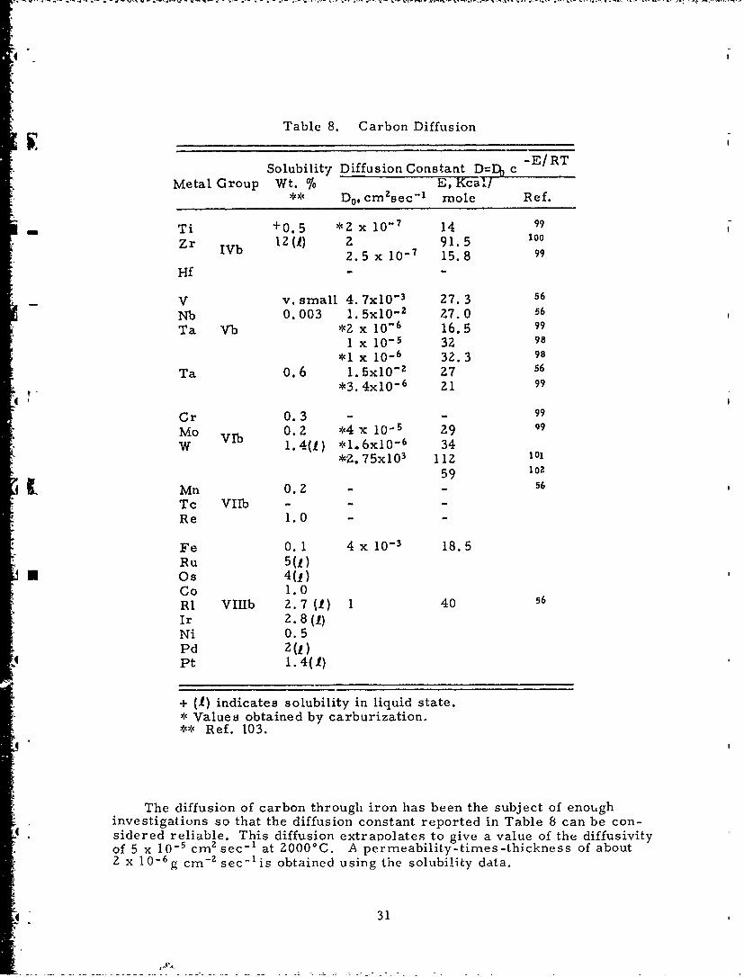
4l
Table 8. Carbon Diffusion
Solubility Diffusion Constant D=DO c -E/RT
Metal Group Wt. % E, Kcal/** D0, cmsec - mole Ref.
- Ti +0.5 *2 x 10 - 7 14 99
Zr IVb 12(l) Z 91.5 100b 2.5 x 10- 7 15.8 99
Hf - -
V v. small 4. 7x10 3 27. 3 56
Nb 0.003 1. 5x10- z 7.0 56
Ta Vb *2 x 10 6 16.5 99I x 10 32 98
*1 x 10 - 6 32. 3 98
Ta 0.6 1. 5x10 "1 27 56
*3.4x10 6 21 99
Cr 0.3 - - 99
Mo VIb 0.2 *4 x 10- 5 29 99
W 1.4(f) *1.6x10 - 6 34*Z, 75x10 3 112 101
59 102
Mn 0.2 - 56
Tc VIIb - -
Re 1.0 -
Fe 0.1 4 x 10- 3 18.5Ru 5(1)
* Os 4(1)Co 1.0RI VITIb 2.7 (1) 1 40 56
Ir 2.8(1)Ni 0.5Pd 2(1)Pt 1.4(f)
+ (1) indicates solubility in liquid state.* Values obtained by carburization.** Ref. 103.
The diffusion of carbon through iron has been the subject of enoughinvestigations so that the diffusion constant reported in Table 8 can be con-sidered reliable. This diffusion extrapolates to give a value of the diffusivityof 5 x 10⁻⁵ cm z sec-1 at 20000C. A permeability-times-thickness of aboutZ x 10-6g cm -z sec - 1 is obtained using the solubility data.
31

There are no comparable data for diffusion of carbon through theborides. A number of borides have been investigated and found to be moreii stable thanthe corresponding carbides. At the same time it has beenfound(83 )that borides do react with carbon to form a liquid phase severalhundred degrees below their individual melting points.
Since carbide and diboride phases tend to exist separately rather thanshowing extensive mutual solubility( 10 4 ), the permeability of a boride to
-- carbon will be expected to be lower than the corresponding carbide by thissolubility factor even though the diffusivities might be equal.
6. Discussion
In order to evaluate the ability of a given coating material to protectgraphite from oxidation, it is necessary to consider what degree of oxygenor carbon permeation is destructive. If carbon penetrates the coating andreacts on the outside with oxygen, the net effect will be to lose carbon at arate equal to the permeation. A value of one per cent weight loss per dayhas been given as a threshold value for the oxidation of graphite. For acoated sphere 10 cm in radius, this rate would correspond to a permeabilityof I x 10-3 g cm- sec- 1 .
The diffusion of oxygen through the coating will produce carbon monoxideat the graphite interface. This condition could cause a pressure which mightdisrupt the coating from the graphite surface. Regular grades of graphitehave porosities of about 15 per cent and permeabilities for reasonable thick-
4nesses of greater than 10- g cm-z sec-V(1 0 ); thus, the whole pore volumewould tend to fill with gas. For a sphere of 10 cm radius, this amount ofgas would cause a pressure of one atmosphere after one day if the permea-bility of the coating were greater than 10-6 g cm-2 sec - . However, if somesurface of the structure were free of the coating, this pressure build-upwould not occur.
A build-up of pressure could also occur if, in a multilayer coating, thereaction to produce carbon monoxide occurred at the internal interface. How-ever, this tendency could be obviated by providing a slight porosity in theinner layer so that the carbon monoxide could diffuse through the graphite.
If the coating is loosened by breaking the bond between the carbon andthe coating material, either by carbon diffusing through the coating or byburning carbon at the interface, a much smaller permeability could resultin coating failure. A permeability of 10-11 g cm -;" sec - i will remove approxi-mately one monolayer of carbon an hour. However, if the coating is 0. 03 cmthick, the induction time before oxygen penetrates the coating is one hour ifthe diffusivity is approximately 10- cm sec - .
Only two measurements of permeability on possible coating materialshave been found in the literaLure. Platinum had a permeability to oxygen ofless than 2 x 10 - 14 gcm - sec - i at 14250C for a one-millimeter thickness(,9 ).
A
32
-

I-
Alumina had a permeability to oxygen of 2 x 10-l 0 g cm-Zsec - 1 at 17000Cfor a one-millimeter thickiness (4 8 . For purposes of comparison, a per-meability of iron to carbon was calculated using measured diffusivitiesand solubilities. A value of 4 x 10- 7 g cm - Z sec- 1 at 1400°C was obtainedfor a one-millimeter thickness.
Examination of the data a .ailable on diffusion constants, oxidation, or,- carburization rate constants and solubilities indicates that metals other
than platinum may have very low oxygen permeabilities. The permea-bilities of the oxides to oxygen are, in general, somewhat greater thanthat for alumina. Since iron has a reasonably high permeability to carbon,lower permeabilities might be expected with other metals or with some car-bides and, especially, borides.
In general, a tight binding between the atoms of the solid leads to a lowpermeability. This condition also leads to a high melting point so thatrefractory compounds in general should -how low diffusivities. The otherfactor of importance is the relative size of the atoms. A tight lattice withsmall nondiffusing atoms leads to a low permeability. At the other end ofthe scale a complete lack of bonding leading to very low solubilities willalso give low permeabilities. This latter case is probably true for oxygenand most of the platinum metals.
Since actual coatings will be expected to be polycrystalline, it is neces-sary to consider both bulk and grain boundary diffusion. In actual practice,however, coatings probably fail due to porosity or nonadherence unrelatedto diffusion. Only where a good coating can be applied and long service isdesired will diffusion through the solid play an important role in limiting thecoating life. In that case, microstructure may be extremcly important.With the possible exception of alumina, no substance is well enough charac-terized -o that its permeability under actual coating conditions can be
* mestimated. Research on coatings should thus be directed to determiningpermeabilities of materials, screened by the other considerations, underconditions relating to the actual coating structure and environment.
B. Volatility of Coating Materials
A detailed example of the importance of vaporization as a factor con-trolling the behavior of coating systems has been presented by M. G. Nicholaset al. (105). This report cites the published data on the volatility of magnesiaand chromium oxides to show that because of their high vapor pressuresthey do not afford protection to a substrate which is subjected to low pres-
U sure environments or the rapid movement of gases over the vaporizingsurface.
33

The volatility of a coating material can be enhanced by decompositioninto a volatile species such as SiOz- SiO or by the reaction of a relatively
II non-volatile material with oxygen to form a volatile material. For example,molybdenum reacts with oxygen to form highly volatile oxides.
Nicholas et al. concluded that both the site and rate of vaporization wereof importance in determining the protectiveness of coating systems at hightemperature. These requirements were listed for properly evaluating the
- vaporization behavior of a coating material; namely (1) the identificatio.'. ofgaseous species, (2) the equilibrium pressures of the gasecus species, and(3) the dependence of the actual vaporization rate on the environmental gaspressure and velocity.
Two approaches to the problem of protecting a surface from attack byoxygen at high temperatures are: (1) to cover the surface with an adherentnon-porous coating of a non-volatile refractory oxide; (2) to cover the sur-face with a metal which resists oxidation, i. e., forms relatively unstablesolid and gaseous oxides and acts as a barrier for oxygen diffusion.
1. Coatings of Non-Volatile Refractory Oxides
In this category are A120 3 , CaO, SrO, ZrOZ, HfOZ, ThO7 , etc. alongwith various mixed oxides such as CaZrO3 , SrZrO3 , MgZAlO 4, etc. Thebinary oxides have been extensively studied by classical Knudsen andLangmuir techniques and by high temperature mass spectrometric methods1O 6).All of these oxides are in equilibrium at high temperatures with their respec-
Stive elements and certain molecular species. For example, AlO(g) isimportant over solid A120 3 (107 ); MgO(g), CaO(g), and SrO(g) are importantspecies over the condensed alkaline earth oxides(10 8 ); and ZrOz(g), HfOz(g),and ThOz(g) are present in the equilibrium vapors over their respectiveoxides(109 . In slightly reducing atmospheres there is also evidence fromoptical and mass spectroscopy for the various monoxides: A10. ZrO, ThO,etc. (11 °) in general, molecular shapes, internuclear distances, and electronicconfigurations are incompletely known for such h:gh temperature species.
There have been only a few quantitative studies of the vaporizationcharacteristics of the ternary oxides, and these have served mainly to estab-lish the heats of formation- for example, see the studies on MgAl2 O 4 (1).No mass spec,;rometric studies are available, and one must consider seri-ously the possibility that a mixed oxide vapor species of high stability couldbe formed and greatly enhance the vaporization rate.
Tables 9 and 10 are taken from a recent report by ChandrasekharaiahZ)and give temperatures at which certain pressures are attained, as well asother data. Clearly, the decompositions to the elements or to suboxides aresuppressed in the presence of oxygen, but the formation of molecular speciesof the same stoichiometry as the condensed phase will be unaffected.
The vapor pressure of thoria has been thoroughly investigated. Shapiro(113)used Langmuir -type experiments and obtained weight losses of thoria fromcoated ungsten filaments in the temperature range 2050' to 2250'K.
34
I

Table 9. Vaporization Data for O.-ides (112)
Temperatures (°K) at Vapor Pressures (torr)
Oxides 10-6 10- 5 10 4 i0-3 i0. 10-1 100
LizO 1175 1263 1358 1466 1576 1694 1825BeO 1862 1995 2143 2300 2490 2710 2950MgO 1600 1714 1841 1968 2128 2330 2535CaO 1728 1858 2000 2148 2323 2553 2795SrO 1600 1687 1790 1897 2000 2123 2247BaO 1358 1459 1570 1694 1822 2000 2198B203 1090 1160 1243 1337 1450 1580 1734A120 3 1910 2037 2178 2339 2518 2735 3000Y20 3 2100 2234 2371 2523 2685 2858 3040La203 1820 1950 2089 2239 2399 2570 2754TiO 1618 1728 1845 1968 2118 2301 2489TiO Z 1800 1919 2053 2203 2377 2582 2825ZrOZ 2060 2203 2350 2512 2679 2858 (3048)HfO Z 2270 2415 2570 2748 2951 3184 3443ThOz 2061 2198 2353 2512 2688 2934 3192VO 1663 1792 1928 2075 2Z39 2410 (2594)MoO2 1368 1455 1550 1654 1762 1879 2004MoO3 762 799 838 878 919 964 1038Wa 2 1641 1738 1845 1954 2075 2193 (2317)W0 3 1138 1262 1352 1409 1449 1489 (1531)UO 2 1754 1884 2020 2165 2333 2535 2786PuO Z 1722 1845 1991 2133 (2285) (2447) (2622)MnO 1384 1502 1622 1758 1901 2056 2223FeO 1413 1521 1644 1774 1914 2070 2239NiO 1300 1400 1510 1629 1758 1898 2046CoO 1368 i476 1570 1683 1824 1972 2138ZnO 1002 1069 1144 1230 1330 1445 1592
.
35

Table 10. Vaporization Data for Oxides(112)
Melting - AHf*(298 ° ) VaporOxide PcintoC Kcal/mole Composition
Li2 O (1700) 142.4 Li 2O, elements, LiOBeO 2530 143. 1 BeO, (BeO)n, elementsMgO 2800 143.8 Elements, MgOCaO 2580 157.8 ElementsSrO 2430 141.8 SrO, elementsBaO 1923 133.5 BaO
V BZ0 3 450 305.4 B70 3, (B20 3)ZAIZC 2015 400.2 Elements, AlO, A1OY20 3 - - YO, a, OzLaO 3 2315 428.4 LaO, 0, 07TiO 1750 124.2 TiOTiOz 1640 225.8 TiOz, TiO, 02ZrOz 2700 261.6 ZrO2
4 HfOz 2310 266 HfO 2ThO2 3050 293.2 ThO zvo - 100 VoMoO2 - 132.4 MOO 3, MoOZ, (MOO 3 )?
MoO 3 795 178.2 (MoO 3)3, (MoO 3) 4, (MoO 3)5WO - 137 WO 2, W03
U W0 3 )473 191 (W0 3 )3, (W0 3 )4 , (W0 3 )SUO 2 2176 259.2 UOzPuOZ - - PuO2MnO 1650 92. 1 ElementsFeO 1420 63.8 ElementsCoO 1800 57. 1 ElementsNiO 2090 57.3 ElementsZnO (1800) 83.3 Elements
* Data were taken from the paper by Ackerman and Thorn( 106).
36
,

An evaporation coefficient of unity was ass ,med for the process. The pre-sure is expressed by
log P =3.71 x 10⁴ + 11.53.(mm) T
There was considerable scatter in the data at 2150'K. Hoch and Johnston(1 1 4 )determined the vapor pressure of thoria by the Knudsen effusion method inthe temperature range 23980 to 2677°K. These investigators used a tantalum
*: effusion cell and obtained the vapor pressure equation.
log P - 37, 695 -7.82 x 10⁻⁴T + 12. 145.atm. T
Their pressurcs were forty times as large as that of Shapiro's. At 20000KHoch and Johnston got 4 x 10- 6 rmi, and Shapiro got 1 x 10- 7 mm for the vaporpressure of thorium. It was ascertained in this work that the tungsten cellsdid not react with the thoria. Ackerman and Thorn("'1) claim that the data
* of Shapiro may be in error because of inaccurate temperature measurements,and those of Hoch and Johnston may be in error as a result of the reductionof ThO2 (g) by tantalum. Darnell and McCollum(116) first used the Langmuirmethod for determining the vapor pressure of thoria. However, they wereconcerned with the question of obtaihing equilibrium in the Langmuir-typeexperiments, so they redetermined the vapor pressure with Knudsen effusionexperiments and identified the vapor species by mass spectrometric means.They used a tungsten Knudsen effusion cell and carried out determinations inthe temperature range 22680 to 25930K. Reaction between thoria and tungstenwas shown to be negligible and the results of the vapor pressure measure-ments are in good agreement with those obtained in the temperature range2500' to 2900°K, by Ackerman and Thorn(115). The results by Ackerman andThorn are expressed by the equation
log 34, 890 + 7. 985atm. T
whereas the results of Darnell and McCollum are expressed by the equation
logP 35,500 + 8. 16.atm. T
The vapor pressure of hafnia was recently reported by Panish andReif(11 7 ). These investigators used hafnia containing 7ZHf 118 which was usedas the radioactive tracer for determining the weight of hafnia deposited onthe target in the Knudsen diffusion apparatus They used a tungsten effusioncell with a thoria liner and an iridium interliner. The temperature rangeinvolved in this study was 19730 to 20560C. Altho-.ogh there was considera-ble scatter in the data, the vapor pressures are quite low; the highestpressure obtained at 20560C was 10 - 5 mim. The scatter in the data was
* attributed to the fact that a puncture in the iriliuin liner led to reaction of
37

the thorium metal (which supposedly resulted from the reaction of tungstenwith thoria) with hafnia.
Ackerman and Thorn(115 ) determined the vapor pressure of zirconiacontaining 2 per cent hafnia in the temperature range 25260 to 2632°K. Theresults (from four experiments) are expressed by the equation,
3. 6 1 x 10⁴ +865.atm. T
*' These investigators, using a tungsten effusion cell, report results which arenot in agreement with the previous work of Hoch, Nakata, and Johnston(I18)who did similar experiments using a tantalum cell. In thelatter case thevapor pressure of zirconia, deter.nined in the temperature range Z0140 to2290°K, is expressed by the equation,
log _ 34, -7.98 x 10- 4 T +11. 98.atm. T
0A Ackerman and Thorn claim that "The results of Hoch et al. are probably inerror because of reaction of zirconia with the tantalum effusion cell. "
A modified Knudsen effusion method was used by Erway and Seifert(119)to determine the vapor pressure of beryllia (BeO) in the range 19500 to2150°C. To eliminate errors due to the columnating effects of a non-idealorifice, they used radioactive 4 Be 7 as a tracer and a columnating devicewhich permitted a collection of the diffusing vapor from the region of theorifice where the cosine distribution law is valid. The activity of the con-densed vapor was measured to get the weight of BeO on the target.
The existing data for the vaporization of these oxides appear to beadequate for assessing their value as potential coating materials with respectto their volatility. That is to say, even though there seems to be some dis-agreement, 4iI the results are quite low; and there is no reason to suspectthat the absolute vapor pressures will present a problem when these refrac-tory oxides are used as coating materials.
2. Oxidation-Resistant Metals
The search for refractory metals which form relatively unstable oxidesquickly leads to the platinum metals. So far, mass spectrometric studieshave established unequivocally the nature of the gas species in the Ru-O, theRh-O, and the Os-O systems(120). An optical spectrum for PtO(g) has been
*reported (121) and preliminary evidence for RuO, RhO, ReO, OsO, and IrOhas also been cited(12 ).
The high temperature vaporization of the platinum metal group hasreceived limited attention. Panish and Reif( 711
7) have measured the vapor,pressure of iridium, rhodium, and ruthenium by Knudsen effusion
380[

and Langmuir methods. Hampson and Walker( 13) have determined the vaporpressure of platinum, iridium, and rhodium using a microbalance techniquebased on the Langmuir method. Similar investigations have been carried outby Dreger and Margrave(2 8 ). The results of the investigations are sum-marized in Tablell. In the case of iridium and rhodium, the duplicated workappears to be in substantial agreement.
- The vapor pressure of the platinum group metals are quite low; how-ever, their usefulness as a coating will be limited by their oxidationresistance. Alcock and Hooper(12 4 ) have studied the vaporization of iridium,rhodium, ruthenium, platinum, and palladium in oxygen in the tempera-
- ture range 10000 to 1600°C by means of the transport technique. Thevolatility of most of the platinum metals is enhanced considerably throughthe formtation of volatile oxides. Rhodium and iridium both showed lowweight losses. The species RhO2 was assumed to be responsible for theenhanced volatility of rhodium; the vapor pressure of gaseous RhO2 isexpressed by:
Plogl0 P(atm) = 1. 079 ± 0. 070 - 9866 ±126 (13)• T
for the range 12000 to 1500'C. Alcock and Hooper assumed IrO 3 as the gaseousiridium oxide and expressed its vapor pressure by
log 1 0 P (atm) = -2.36 - 906/T (14)
for the range 12000 to 1400'C. The remaining metals of the group showedappreciable weight losses in the presence of oxygen.
In addition to the work of Alcock and Hooper, the high temperatureequilibrium vapor pressure of iridium oxide has been studied by Schaferand Heitland(O25) and Cordfunke and Meyer(126 ).
Sch~fer and Heitland(25)
PlrO3 -
logl 0 K (atm.) = log 10 -P/ = -892/T - 2. 354. (15)
Cordfunke and Meyer( 126)
logl 0 K (mm) = log, 0 (r = -2034/T -7. 346. (16)
P~ P
After conversion to atmospheres and to K PIrO3 (to be consistent withp- p - 3/- 2• (Po )
the notation of others), Equation 16 becomes
39
! .

-'_IrO3logl 0 K p logi 0 (po') /2) -1017/T -2.23. (17)
\(Tod atm
Alcock and Hooper(124)
log 0 atm. = -906/T -2. 36. (18)
Note: To be consistent with Cordfunke and Meyer(12 6 ) and Schi'fer andHeitland( 125), it is obvious that Equation 14 should read:
logl0 K (atm.) = -906/T -2. 36 (19)
where
K<- ~r(20)P (p)I 3/Z "
Comparison of Equations 15, 17, and 19 shows all three research groups to bein substantial agreement.
Similar weight loss studies in air at temperatures up to 1400'C have beenconducted by Krier and Jaffee(127)for osi-nium, ruthenium, iridium, platinum,and rhodium. The oxidation resistance of these metals was found to increase
i in the order listed above, as shown in Figure 2. Hill and Albert(12 8 ) mea-sured weight losses as a function of temperature and oxygen pressure forplatinum (14000 to 1700°C), rhodium (14000 to 18000C), and palladium (14000to 15000C). Again, the weight loss was found to increase rapidly with increas-ing oxygen pressure; but Hill and Albert(s2 8 ) refrained from expressing theirresults in a quantitative equation.
Fryburg(129 ), Fryburg and Petrus(130) , and Mitani and Harano(1 3 1 ) foundthat atomic oxygen oxidized platinum faster than molecular oxygen, at leastat temperatures up to 10000C.
C. Chemical Compatibility of Coating Materials
1. Oxides on Graphite
The chemical stability of several refractory metal oxides and graphitehas been investigated by Johnson(132). He qualitatively determined the maxi-
*Q * mum temperature of stability by subjecting the bulk oxide and graphitearticles, which were in surface-to-surface contact, to high temperatures
- achieved by 1000C increments. No experimental details were presentedin regard to the criteria for reaction, whether the process involved reduc-tion to the metal or carbide formation. The results of this study arepresented in Table 12. The rate of graphite reduction of the metal oxides,
0e
~40

TEMPERATURE (*C)I j , I I i I1500 1300 1100
1600 14:00 1200 10
OSMIUM , ,
102 RUTHENUM
IRIDIU
'~~~~---- ,O - -'
- 3 - -
S)ATINUM
RHOO I
4 9-55 6 65 7 5~ PO48 5RECIPROCAL TEMPERATURE
Figure 2. Oxidation of the PlatinumGroup Metals (127)
Trable 11. Vapor Pressure Data- Platinum Group Metals
*Reference 117 Reference 123 Reference Z08
Temperature Temperature Temperature(Log P atm.) Range *1( (Log P atm.) Range IK (Lug P atm.) Rlange 'K
Or 7.58 33.980/T 2100-2600 7. 13 - 33, 337/T 1486-2260 7.23 33,680/T 140-2477
Rh 7.40 -28,300/T 2050-2200 6.89 - Z7.276/T 1709-2075 1744-Z068
Ru 7.88 -33,550/T 2000-2500 8.31 -33,600/T 2011-2330
*Pt 6.76 - Z7,575/T 1916-2042 7.47 - 9,1001T 1571-1786
41
0

Table 12. Minimum Reaction Temperatures forSever.- Compacted Metal Oxides andGraphite
Metal Oxide Minimum Reaction Temperature
ThOz 2000 0 CZrOz 1600 0 CMgO 1800 0 CBeO 2300 0 C
AlZO3 , BeO, MgO, TiOz, and ThO2 , has been investigated by Komarek et al(133).In this investigation mixtures of powdered metal oxide and graphite wereheated to the desired reaction temperature and the reduction rate followedby observation of carbon monoxide evolution. The reported rate laws sum-marized in Table 13 were calculated for the first few per cent of reduction.
Table 13. Rates of Graphite Reductionof Several Metal Oxides
Temperature Experimental Specific Rate
Metal Oxide Range Constant (mrnmoles CO/ 10, 000°K particles Metal Oxide/second)
MgO 1625-1831 kL=6 . 34 x 10"Zexp (-59, 800/RT)
Spinel(A12 0 3-MgU) 1888-1988 kL=l. 8 x 10 -Zexp (-59, 500/RT)I BeO 2018-2186 k= 7. 64 x 10 3 exp (61, 300/RT)BeO 1788-2018 k -1.01x 10- exp(40,000/RT)
AlzO2 1580-1723 kp =2. 42 x 10'8 exp (316,000/RT)ThO2 1430-1550 could not be accurately determinedTiO2 929- 959 could not be accurately determined
Since kinetic data were obtained for ThO z and BeO at temperatures con-siderably below those minimum reaction temperatures rep.rted by Johnson(13Zit would appear that the latter data were in error; however, it is possiblethat in the case of compacted reactants, the metal carbide formed, prevent-ing further reaction. The reaction with BeO i. further complicated by thefact that more than one reaction takes place( 134)
42

()BeO +I/Z C 1/Z BeZC + CO(s) (s) (s) (g)
(Z) BeZC(s) --- 2Be(g) + C(s )
(3) Be(g) + CO(g) - BeO(s ) + C(s )
Bockris et al.(135) have calculated the free energy of graphite reductionof several metal oxides using data from Coughlin( 6) and Brewer(137). Thecalculated CO equilibrium pressures are summarized in Table 14.
Table 14. Equilibrium Pressures of COat2000°K for Reduction of Oxides
Reaction -F2000K PC (atm)(cal) c
1/z TiO2 +3 /2C -- '/? TiC + CO 24, 310 452.91/z SiOz + 3/zC7- 1 /z SiC + CO 4,490 3.09
1/3 A10 3 + 3/zC:!/ 6 A14 C3 + CO -9. 107 0. 10
/z ThOz + 2C --1 /z ThC2 + CO -12,940 0.038
Schulz et al. (138) have also examined the thermodynamic data for thegraphite reduction of several metal oxides; their results are summarizedin Table 15.
Table 15. Temperature at which the EquilibriumPressure of CO is one atmosphere forthe Graphite Reduction of Several Oxides
Temperature (°K) at
Reaction which PCo = I atm.
'/z TiOZ + 3/z C -l/z TiC + CO 15801/z SiOz + 3/2 C - 1/z SiC + CO 1720
1/3 BzO3 +7/6 C I/6 B4 C + CO 18301/z ZrO2 + 3/ZC 1/2 ZrC + CO 2010
/? ThOz + 2C --1/z ThC2 + CO 2190
1/3AzO23 + 3/z C !z 1 /6 A14C3 + CO 2200
BeO + 3/,C- 1/z B2 C + CO 2490
MgO + C -,-Mg + CO 2110
43

Zirconium dioxide, reported to react with graphite at minimum tem-peratures of 13000(139 )and1600oC(137), is summarized by the followingequation:
ZrO(s) + 3C(s) - ZrC(s) + 2CO(g)
Prescott(140)found from equilibrium data that AF ° = 151, 800 -78. 68T, or- P C is one atmosphere at 16570C. Kutsev et al. (41)report the reaction to
pro eed according to
ZrO2 + 2. 63C - ZrCo.7 1 00.08 + 1.92 CO.
- However, at a later date Zhelankin et al.(142 ) report compositions varyingfrom ZrCO.640 0. 0 6 to ZrCO. 7 7 0O. 0 0 at temperatures of 19300 and 24500C,respectively.
The reaction of hafnium dioxide with graphite(143 ) is summarized by
HfO2 + 2. 9C -= HfC0 . 9 500.05 + 1. 95CO.
The free energy change for this reaction in the temperature range 17500 to20000K was found from equilibrium data to be in accord with AF ° = 132, 300-66T or P = one atmosphere at 17320C.
Prescott et al. (144) report a free energyj change: AF ° = 176, 970 -73. 89T,for the reaction ThO + 4C -ThC I 2CO. The temperature range investi-gated was 17070 to 20680C. The partial pressure of CO was calculated tobe one atmosphere at 21220 C . Nadler et al. (145) report the ThOz reductionto proceed to the dicarbide in the temperature range 16500 to 17300C.
The results of the cited experimental data and thermodynamic cal-culations indicate that there probably is no oxide that is stable with respectto graphite at 20000C if one considers the criteria for stability as a COpartial pressure of less than one torr. Table 16 lists the calculatedequilibrium pressure of carbon monoxide for the carbothermic reductionof several oxides at 20000C. Beryllia, the most stable oxide with respectto carbon, has a CO pressure of 0.2 atmosphere (15Z mm Hg).
It may be possible to produce an oxide-graphite system which is use-ful from a kinetic point of view; however, no kinetic investigations havebeen carried out utilizing solid compacted reactants which have surface-to-surface contact. Very likely it will be necessary to utilize a barrier iaterialbetween the graphite and refractory oxide coating to prevent reduction of theoxide. Furthermore, this barrier must be chemically and physically com-patible at high temperature with both the graphite substrate and the oxidecoating. Possible barrier materials include metal siicides, carbides,nitrides, and borides since these classes of compounds contain some of themost refractory materials known. The nitrides are quite similar to the
44

Table 16. Calculated Equilibrium Pressure ofCarbon Monoxide for the CarbothermicReduction of Oxides at 2000*C.
Reactant +C to -AF at 2000 0 C P (atm) Ref.yieldMetalC+CO (Kcaligatm 02) CO
TiO2 29.8 756 138
SiO2 23. 2 167 138
BZ0 3 17. 1 44 138
ZrO2 13. 1 18 138
12. 6 16 140
ThO 2 9. 1 7.5 138
4.5 2.7 144
A1 2 0 3 6.9 4.6 138
BeO -7. 1 0.2 130
MgO 15.0 27 138
HfOZ 3.9 Z. 4 143
carbides in their general chemistry except that they are more easily oxidized;hence, they offer no advantage over the carbides.
2. Multilayer Coatings
Since the most likely approach to graphite oxidation protection at 2000"Cis the utilization of a multilayer coating, the problem is to discover arefractory carbide, boride, or silicide which is chemically and physically
* [compatible with respect to graphite at 2000°C. The simplest oxidationresistant coating would be that formed from the oxidation of the barriercompound in that this reaction would preclude the necessity of applying anoxide to the barrier material. Of course, precise methods must be developedwhich will produce a pore-free oxide coating.
a. Refractory Carbides
Metal carbides are among the most refractory materials known; andsince many are compatible with graphite, they are worthy of considerationas graphite oxidation protective coatings.
*Carbides may be conveniently divided into three groups. ionic, covalent,and interstitial( 146 ). Ionic carbides are formed from the metals of periodicgroups I, II, and III. When they are treated with water, hydrocarbons areevolved. These carbides are summarized in Table 17.
The ease of hydrolysis of these carbides suggests questionable utility ascoating materials, however, the hydrated oxides which form may inhibit fur-ther hydrolysis, thus yielding stable ambient coatings.
45
A~

Table 17. Ionic Type Metal Carbides
Carbide Formula Metal
MzCz* Li, Na, K, Rb, Cs, Cu, Ag, AuMCZ Be, Mg, Ca, Sr, Ba, Zr, Cd, Y
La, Ce, Pr, Nd, Sm, Th, V, UMZC 6 Al, CeMzC BeM 4C3 Al
* M stands for metal.
Brewer(147) reports the following stabilities in vacuo:
Stable to 2500*K: ThCz (slowly volatile)Stable to 2000'K: UC, UCZ, ThCz, VCStable to 1500°K: Previously cited materials
plus rare earth carbides.
The melting points of the ionic carbides and the corresponding metaloxides are presented in Table 18. Since the majority of these ionic carbides
Table 18. Melting Point of Ionic Carbides andCorresponding Metal Oxides (°C)
Metal Carbide, Oxide Melting Point, ^C Ref.
Al 4 C 3 3073 135
BeZC > 2373 13s
CaCz 2573 135
SrCz > 2200 135, 148
ThCz 2928 135, 148
ThC 2898, 2625 135, 148
UG 2723, 2793, 2250 13S, 148
UCz 2623, 2673, 2350, 2400VCz 3103, 2830 135, 148
YCz 135, 148
ZnCz13MgC2 550CeZC6BaGzLaCzAlzO3 2015 149BeO 2550 IsO
CaO 2600 11oSrO 2415 I50ThOz 3300 151
ThOz 3300 I51
UOz, U30 8 2280, 750 (decomp. 15)UO2, U30 8 2280, 750 (decomp. )V'O 3 1977 ISO
Y'0 3 2410 15ZZnO 1975 150
MgO 2800 ISO
C CeOZ > 2600 152
BaO 1917 ISO
LazO, 2305 I5O
46I-

have high melting points, as do their metal oxides, they exhibit potentialas coating materials.
Only two refractory covalent carbides are known, SiC and B4G; andthey are both quite chemically inert at room temperature, oxidation occurs
- at elevated temperatures(148). Silicon carbide is the coating currently inuse, B4 C would not be an improvement over SiC since the cx.dation products
* of B4 C are GO, GO2 , and B 2 0 3 (melting poin' 577 0 C).
The interstitial carbides are summarized in Table 19. Carbides oftypes M 3C Z and M 3C also hydrolyze to yield hydrocarbons and are there-fore less attractive.
Table 19. Interstitial Type Metal Carbide
Carbide Formula Metal
MG Ti, Zr, Hf, V, Nb, Ta, Mo, WM2C V, Mo, WM 3 CZ CrM 3 C Mn, Fe, Co, Ni
The melting point data for the interstitial metal carbides and the cor-responding metal oxides are presented in Table 20. These data indicatethat ZrG, HfC, 4TaG:ZrC, 4TaC:HfC, and possible TaG are worthy ofinvestigation.
Table 20. Melting Points of Metal Carbideann Corresponding Metal Oxide
Material Melting Point (C)
Carbon MetalCarbide Ref. Oxide Ref. Carbon Eutectic Ref.
Ti (3 0) 3140 148 1840 153 2610 154
Zr 3420 154 2677 150 2850 154
Hf 3830 154 '777 15O 3150 154
, Nb 3480 209 1772 I5O 3220 z09
Ta 3877 148 1890 150 3325 154
4Ta: Zr 3932 148
4Ta: Hf 3942 148
Cr 1890 (C r3CZ)148
Mn 1520 (Mn 3 G)1 1 8
Fe 1650 (Fe 3 C) 148
47
-0

The carbides Cr 3C2, Mn 3C, and Fe3 C do not appear useful in that theyhave melting points of 18900, 15200, and 16500C, respectively. The car-
• bides of type M2C would not be expected in the presence of excess graphitesince further reaction would be expected to yield MC.
A further requirement of the graphite protection system is the stabilityof the metal oxide-barrier component with respect to chemical reaction athigh temperature (i.e., -Z000°C).
Schulz et al. (138) have calculated that for the reaction,
2ZrC + ZrOs 3Zr( )+ 2CO(s) (s) (g)'
the free energy change is zero at 2918'C. Berkowitz-Mattuck(155)calculatedthe combined pressure of CO and CO which would be developed at the inter-face between metal oxide and metal carbide when the metal oxide is formedby the 02 oxidation of the carbide. Rupture of the coating was assumed totake place at that temperature corresponding to an equilibria CO-CO2 pres-sure of one atmosphere. The results of these calculations are summarized
g in Table 21. The two most promising carbides, in terms of oxidation resis-tance, are HfC and ZrC.
Table 21. Potentiality of Carbides forOxidation Resistance(1
4 )
* Melting Most common Oxide Maximum tempera-Carbide Point formed on the Metal ture of Stability of
0C during Oxidation Oxide on Carbide, 0C
TiC 3140 TiOz (rut) 1230ZrC 3540 ZrO2 >1730HfC 3887 HfO2 1730VC 2810 V205 670NbC ca. 3900 NbO2 830TaC 3880 Ta20 1030CrC, 1890 Cr 20 3 1130MoC - MoO? -WC 2870 W0 2 730
The rate of oxidation of HfC was investigated by Berkowitz-Mattuck(15).A single kinetic run at a PO. = 4. 2 torr was carried out at 2305'K. The
*oxidation rate appears parabolic, which implies some oxidation protectionby the HfO2 formed; however, only a very limited amount of data was reported.
Bartlett et al. (156) investigated the reaction between oxygen and ZrC.ZrC powder was heated in the temperaturc range 450' to 580'C at 02 partial
48
-0

pressures varying from 0. 1 to 1.0 atmospheres. The kinetic data indicatedthat two parellel, independent processes took place: one diffusion-controlledof short duration and a second surface-controlled process between ZrOz andZrC which was the main oxidation path The enthalpy of activation for thediffusion-controlled step was calculated to be 53 Kcal/mole and that of thesurface-controlled rate, 46 Kcal, mole. In any event, since these data wereobtained at relatively low temperatures when compared with 20000C, anextrapolation of the kinetic data to the higher temperature cannot be justified.
b. Refractory Borides
The borides constitute another class of refractory materials. The rareearths and alkali metals form borides and, unlike the carbides of thesemetals, the borides are stable in the presence of moisture. The stabilityof the borides with respect to graphite and oxidizing atmosphe'e has beeninvestgated by Brewer and Haraldsen( 157), Glaser(158),Steinitz(5 9 )and cited byCampbell(148). The metal borides were heated in the presence of graphiteto the desired temperature and, after cooling, the charge was examined byX-ray diffraction for the presence of metal carbide. The results are pre-sented in Table 22(148)
The bases for selecting a boride barrier material are stability withrespect to graphite, oxidation resistance, and formation of a metal oxidationproduct with a melting point greater than 20000C. Possible choices aresummarized in Table 23. The most promising borides appear to be ZrB2and HfBZ; however, it should be noted that no data have been reported con-cerning the stability of HfB? with graphite.
c. Refractory Silicides
The possibility of using silicide coatings should not be overlooked inthat SiO z inight act as a flux to produce a metal oxide pore-free coating. Ifone could minimize the outer exposed surface-to-volume ratio for SiO2 ,silicides could be useful. Furthermore, the oxidation of a silicide providesa method of applying the oxide coating.
The binary silicon compounds which have melting points greater than200000 are listed in Table 24.
The oxidation of the silicides listed in Table 23 would yield SiO Z andthe metal oxide. As previously stated, it is hoped that the SiO z will act asa flux to produce a pore-free coating. One of the requirements of the silicidesystem is that the derived metal oxide has a high melting point, prefer-ably above 20000C. Those metal oxides derived from the cited silicidesare listed in Table 25.
The silicides of Zr and Hf appear to be the most promising in view ofthe melting points of the silicides and the corresponding metal oxide. Nosystematic investigations concerning the reactions of these silicides withgraphite have been reported. However, Robins and Jenkins e74 )measured theheat of formation of several silicides using calimetric techniques. Thesedata are presented in Table 26 along with the heats of formation of the metalcarbides. 49
-0 4

Table 22. Metal Boride Stabi.lities
With Carbon Oxidizing Environment,
Stable at Unstable at Maximum Stable1500 0 C 1500 0 C Temperature, °C
CeB 6 BiZB VBz (1000)TiB2 TiB MozIB (1000)ZrB2 TiZBs NbBz (1100)*VBZ ZrB TaBZ (1100)*, **NbBz ZrB1z WB (1100) *, **TaB2 NbZB ZrBa (1300) **CrzB NbB "2 (1400)Cr 3 B 2 Nb3 B4CZSB 3 Ta 2BCrB TaBCr 3 B 4 Ta 3B 4
CrB2 ThB44 Mo2 B Cr 4B (?)
Mo 5 B 3 CrzB5
MoB MozB (7)MoB Z CeB 4Mo 2 B 5
WBUWzBS
FeBThB 6FezBCo 2BCoB
4 NiZB
Semi-protective film formed during oxidation at lowtemperature.
* Oxide films formed at high temperatures were porous.
O
50
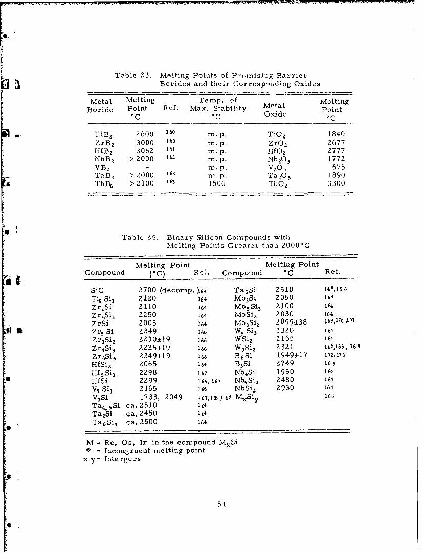
Table 23. Melting Points of P-,misirg BarrierBorides and their Corresp,d~ng Oxides
Metal Melting Temp. o'f MeltingBoride Point Ref, Max. Stability Metal Point
0C °C Oxide oC
TiB2 2600 160 m. p. TiOz 1840
ZrB 2 3000 160 m.p. ZrOz 2677HfBz 3062 161 m.p. HfO2 2777NbBz > 2000 162 m. p. NbZO3 1772VBz - m.p. V 20 5 675
TaB, > 2000 162 rn.p. TaO 5 1890ThB6 > 2 100 163 1500 ThO z 3300
Table 24. Binary Silicon Compounds withMelting Points Greater than 2000°C
Melting Point Melting PointCompound ( 0 C) R':. Compound 0 C Ref.
SiC 2700 (decomp. 64 TasSi 2510 148,15 6
Ti5 Si 3 2120 164 Mo 3Si 2050 164
Zr 2 Si 2110 164 Mo 5 Si 3 2100 164
Zr 5 Si 3 2250 164 MoSi z 2030 164
ZrSi 2005 164 Mo 3Si 2 2099±38 169,170 A7
Zr5 Si 2249 165 WS Si 3 2320 164
Zr 3Si 2 2210±19 166 WSi 2 2165 164
Zr 4 Si' 3 2225±19 166 W 3Si 2 2321 165,166, 169
Zr 6Si 5 2249±19 166 !36 Si 1949±17 172, 173
HfSi z 2065 164 D3Si 2749 165
Hf5 Si'3 2298 167 Nb 4 Si 1950 164
HfSi 2299 165, 167 Nb5 Si 3 2480 164
V5 Si3 2165 164 NbSi z 2930 164
V3Si 1733, 2049 167,163,1 69 MXSi 165
Ta 4 .5Si ca.2510 164TazSi ca. 2450 164
cTasS3 ca. 2500 164
M = Re, Os, Ir in the compound MxSi= Incongruent melting point
x y= Intergers
51

Table 25. Melting Points of Metal Oxides Formed by theOxidation of High Melting Point Metal Silicides
Metal Combined Metal Oxidewith Si Formula Melting Point (0C)
Ti TiO2 1840
" Zr ZrOz 2687
Hf HfOz 2777
V V2O 5 675
Ta TaZO5 1890Mo MoO 3 795W W0 3 1473
Nb NbzO 3 1772
Ta TaZO 5 1890B B20 3 450
Table 26. Heats of Formation of
Metal Silicides and Carbides
Compound A Hf Kcal/g. Atom of4 C or Si
Ti 5Si3 46TiSi 31TiSi z 16TiC 57, 44
IE Zr Si 3 49Z rSi 35ZrSi z 18ZrC 40
The limited data in Table 26 show that the heats of formation of thesilicides for the lower silicide are of the same orders as the carbides; hence,one may expect the same order of stability.
D. Mechanical Compatibility of Coating Materials with Graphite
The mechanical problems associated with the use of refractory materialsin contact with graphite are especially complex. The protective coatingmust have thermal expansion properties similar to those of the graphite sub-strate. Even in systems with perfectly matched thermal expansions, thermalgradients will produce stresses which will be most pronounced during rapidheating or cooling (thermal shock). Thus, both the coating material and the
52

coating-to-graphite bond must be strong enough to withstand these stressesThe coating-to-graphite bond may be purely mechanical, it may be a seriesof solid solutions ranging from pure graphite to the pure coating material,or a new compound (e. g. , a carbide) may be formed at the interface. Inthe last two cases, a multilayer coating is involved where the mutual mechan-ical compatibility of more than two materials needs to be considered. Theproblem is further complicated by the fact that the coating-to-graphite bondand the properties of the coating material itself may markedly change dur-ing prolonged service at high temperatures due to grain growth, annealing,carbon diffusion, chemical reactions of the coating material with eithergraphite or oxygen, or any combination of these factors. The oxidationprotection afforded by any material other than the oxides and the preciousinetals is due t: the format'on of cn oxide film, and good adherence of thisoxide layer is essential for c. ntinued protection.
Thermal shock resistance of a coating system also depends on the bondstrength, and, further, on the thickness and thermal conductivity of the coat-ing, the difference in the thermal expansion of coating and substrate, andthe shock resistance of the pure coating material. The latter is proportionalto
R= and/or R' = kS , where S is theE oc E c
fracture strength, E the modulus of elasticity, cx the linear thernal expan-sion coefficient, and k the thermal conductivity. On very rapid heating(or cooling), only the first thermal stress resistance factor R needs to beconsidered, whereas the second thermal stress resistance factor R' becomespredominant at low heat transfer rates. The subject of thermal shock hasbeen extensively discussed by Kingery(175), who lists R and R' for a largenumber of refractory materials.
Other properties which are related to the mechanical compatibility andmust be considered include the emittance of the coating material which,for a given heat flux rate, determines the equilibrium temperature of thesurface and possibly the radiation resistance of the coating material. Finallythe lowest melting point or eutect;c temperature in the coating system willproba'Ay constitute the upper temperature limit for useful oxidation pro-tection. More extensive general discussions of the mechanical compatibilityare presented in two excellent reviews by Krier (176) and Pentecost(177)
1. The Physical Properties of Graphite
The physical, mechanical, and thermal properties of graphite can bevaried over a wide range. Graphite substrates can be "tailor made"(within limits) to conform to the requirements of a particular coating mate-rial, a characteristic which greatly facilit .tes solution of the mechanicalcompatibility problem.
The discussion will be limited to the properties of manufacturedgraphite grades, as opposed to the properties of naturally occurring singlecrystals. Formed graphite is prepared by mixing a graphitizable carbon,
53

such as milled petroleum coke, with tar or pitch binders, the mixture isextruded or molded to shape under pressure, baked, and then graphitizedat temperatures in the neighborhood of 2600'C in resistance furnaces. Thedesired graphite properties are achieved by suitably selecting the rawmaterials and/or processing conditions.
-Graphite is uniquely suited for high temperature structural applicationsbecause of its low density (1.6 to 2.0 g cm- 3 ), easy machinability to closetolerances, high thermal conductivity and, hence, thermal shock resistance,and high strength at high temperatures. The tensile strength of graphiteincreases approximately two-fold from room temperature to about 2500°C.Figure 3 shows a comparison of the relative tensile strength (strength onan equaL weight basis) of a manufactured graphit and varicus otner hightemperature materials 1 8).
104 BEST HIGH TEMP ALLOY (1945)
- -PURE
SINTERED PURE SINTERED ALUMINAZ
n GRADE ECA \__ GRAPHITE
SINTE EM; Be'-'
in 0 1000 2000 3000 4000 5000 6000TEMPERATURE (OF)
Figure 3. Tensile Strength-to-Weight Ratiosvs. Temperature for High TemperatureMaterials
Manufactured graphites are nearly always anisotropic because theindividual crystallites are preferentially oriented as a result of the extru-sion or molding process. Hence, most properties need to be determined
* 'in both the "with-grain" and "against-grain" directions. Extruded graphiteshave one with-grain and two against-grain directions and gcnerally higheranisotropy than molded grades, which exhibit two with-grain and one against-
*. grain direction. Young's modulus, strength, and electrical and thermalconductivities are always higher with-grain, whereas the thermal expansionis higher against-the-grain. For coating work, graphites with a very low
*l degree of anisotropy are desirable.
54
6-

A close matching of thermal expansion of substrate and coating is ofgreatest importance to the mechanical compatibility problem. Figure 4shows the thermal expansion coefficients of various graphite grades asa function of temperature(179 ). Graphites with even higher and lower thermal
0 LAPOL ASE sTo KLQ20
tEL %'8 o LA INBLAC T EMPRAUR ( 0 ,,,400-
,, ME'rALLURGCAL COKEASE STOCKILON )
COARSE- GRAINED-PETROEUML
Z '' " OKE BASE STOCK L ONG),,
C 400_ L80 0 j12 00 1600 2000 2400iW~FINAL TEMPERATURE VVC
Figure 4. Mean Coefficient of Thermal Expansion ofGraphite vs. Temperature (Optical DilatometerMethod).
expansion coefficients than those shown in Figure 4 can be and have beenmade. The curves in Figure 4 are very nearly parallel; the mean thermalexpansion coefficient to any higher temperature can therefore be approxi-mately calculated for any graphite with known expansion in the 20' to 100°Crange merely by adding the values listed in Table 27(180)
Table 27. Factors for Calculation of Mean Coefficientof Thermal Expansion
Final Added Final Added
Temperature Factor Temperature Factor
100 0C 0 800 11.4200 2. Ox10- 7 /oC 900 12.3300 4.0 1000 13.2400 6.0 1500 17.2
* 500 7.7 2000 21.2600 9.2 2500 25.2700 10.4 - -
55
0T

Other graphite properties can likewise be varied considerably. Theproperty ranges for manufactured graphite grades are listed in Table 28which does not include graphite specialties such as whiskers, fibers,foams, and pyrolytic graphite. The listed property ranges per:tain tographites but there is no clear distinction between graphites and carbons.Carbons are defined as incompletely graphitized carbonaceous materialsand have generally higher strength and lower thermal and electrical con-ductivities than graphites.
Table 28. Physical Properties of Manufactured Bulk Graphite
A. Non-Directional Properties
Melting PointSublimation Temperature 3650 :Z5°CHeat of Vaporization 170. 4 Kcal/g atomVapor Pressure 3.8 x 10- 3 mm Hg at Z500 0CDensity g cm 3
1. Calculated from lattice constants 2. 27 - 2.282. Helium displacement 2. 10 - 2. 183. Bulk density 1.50 -2. 10
B. Directional Properties With Grain Against GrainYoung's Modulus (106 psi) 0.5 - 5 0.5 - 5Tensile Strength (103 psi) 0.5 - 10 0.5 - 5Compressive Strength (103 psi) 1.0 - 30 1.0 - 30Flexural Strength (103 psi) 0.5 - 15 0.5 - 10Coefficient of thermal expansion
(I/./ 0 C) x 10 - 7 2.0 - 65 10 ->100Thermal Conductivity, cal-cm/sec cm 0 C 0.05 - 0.8 0.05- 0.5Specific Resistance, 10- 4 ohm-cm 3.0 - 30 5.0 - 50
It should be noted that many of the properties listed in Table 28 areinterdependent. Therefore, if there is a specific requirement (e. g. , thevalue of the thermal conductivity or thermal expansion), the range overwhich the other properties may be varied becomes narrower. The samecondition is true if a highly isotropic graphite is required.
The high temperature properties of graphite have been reviewed byWright(lTM). Once the requirements are known from the properties of thecoating material(s), the selection of a specific graphite is facilitated byreviews by Cacciotti('82 )and by Glasser and Few( 18 3 ). The latter authorsin particular list the physical properties, availability, price, and manu-facturer of every graphite now produced in commerical quantities in theUnited States. For easier selection, each grade is again listed in separateindices for shapes and sizes, unique characteristics and applications, com-position, and for all important pLysical properties where appropriate inboth the with- and against-grain 6irections. However, the properties of
56

most graphites are given only within rather broad ranges. Furthermore,some of the stated values appear erroneous; e. g., the room temperaturethermal expansion coefficients for some grades are listed to be above200 x 10- 7cm/cm/°C in both the with- and against-grain directions, valueswhich appear improbably high. More detailed information is frequentlyavailable from the manufacturers. The properties of commerical graphitesproduced by Union Carbibe Corporation, Carbon Products Division, arelisted in detail in the Industrial Graphite Engineering Handbook(184).Extensive property data are available for seventeen grades newly developedfor aerospace use(185). This report includes six high-density recrystallizedgraphites, six grades in which the fillers are shredded or woven carbonizedcloths, five pressure cured and/or impregnated grades, and a standardpremium grade for comparison purposes. Both room temperature and hightemperature properties are listed; statistical variations are included and themethods of measurement are detailed.
Many grades of graphite are produced for particular applications (e. g. ,nuclear graphites, electrodes, molds, etc), and have properties which areuniquely suited for a specific use. Therefore, although reference 185 lists
* '" almost 200 bulk graphites grouped into 123 product classes, there is noassurance that any of these grades will possess the combination of propertieswhich will provide an ideal substrate for a particular new coating system.Ultimately, a new graphite would probably have to be developed for thispurpose; however, the wide variety of available graphites certainly facilitatescoating research and will, in many cases, permit a preliminary coating* Levaluation. Certainly, such a choice reduces the likelihood of a gross mis-match in the properties of substrate and coating.
2. Physical Properties of Potential. Coating Materials
Most physical propert-es of the potential coating materials are knownand readily accessible from a number of reference works, books, andreviews. This information is, howe-,r, only a limited value for solving themechanical compatibility problem. it has already seen pointed out that thechemical composition of the coating may change in time due to diffusion orreactions with the graphite substrate and/or oxygen. Even if this changedoes not occur, the physical properties of the coating may be different fromthose measured on the bulk material and will frequently vary with the coat-ing method. Selection of a coating method depends upon, among otherfactors, the required coating thickness, since some methods (e. g. , sput-tering or vacuum metallizing) are suitable for thin films only, whereasothers (e. g. , flame spraying) will inherently produce thicker coatings. The
*methods suitable for coating graphite have already been reviewed in Section 1of this report. Vapor plating frequently produces highly oriented coatingswith properties very similar to those measured on single crystals of the coat-ing material. Coatings of less than theoretical density (including flame orplasma sprayed and all sintered coatings) shoald have properties approximatingthose of sintered bulk specimens of similar density. Thus, the physicalproperties of the bulk material can only be used as guide lines for the selec-* tion of a graphite grade most suitable for a particular coating and coating
57
S

process. For these reasons, and also because there are virtually thousandsof articles dealing with the physical, mechanical, and thermal propertiesof potential coating materials, original papers have been reviewed here onlyif the information was not readily available. For compiling the data oncoating materials and for comparing their properties with those of graphite,sources of condensed information have been used extensively. The mostcomprehensive compilation of thermodynamic data - including heats of
- formation, heat capacities, enthalpies, and entropies as a function of tem-perature, melting or decomposition points as well as spectral and structuralinformation- can be found in the JANAF Thermochemical Tables(1 8 )Essentially all elements, oxides, carbides, borides, and nitrides of interestas coating materials are covered. The information is contained in loose-
- leaf sheets and is continuously revised and updated by the issuance of newpages. Similar thermodynamic information has been compiled by theU. S. Bureau of Mines( 1 8 7 ). The general physical properties of refractorymaterials, including the densities, melting points, and eutectics with othermaterials, specific heat, thermal conductivity and thermal expansion, vaporpressure and electric resistance, are listed in the Handbook of ThermophysicalProperties of Solid MateriaLs(188). This survey is particularly valuablebecause it is not confined to a compilation of properties, but rather alsolists the method by which the measurements were carried out and includesother pertinent information, such as specimen preparation and analysis.More recently, an extensive report on the properties of materials meltingabove 1500oC has been compiled by researchers from the Battelle MemorialInstitute(189 ). This report also contains tables and graphs illustrating theranges over which properties of various classes of materials (e. g. , singleor mixed oxides, carbides, etc. ) may be expected to vary. Unless notedotherwise, the data used in the following discussion have been taken fromthes, compilations. More condensed property listings can be found in variousbooks or reviews dealing with high temperature materials or coatings(190,191,19z).Lawrence Radiation Laboratory has published extensive bibliographies onrefractory carbides 93 )and on refractory oxides(194).
A close match of the thermal expansions of substrate and coating(s) isby far the most important consideration for predicting the mechanical com-patibility of a system. Figures 5, 6, 7, 8, and 9 illustrate the thermalexpansion of various potential coating materials.
A numbe- of oxides (e.g. , BeO, ZrOz , and ThOZ), at least one carbide(TiC), and the platinum group metals (except possibly iridium) have thermalexpansions so high that they cannot at present be matched with any graphite.In some cases, this incompatability can be mitigated by employing a'graded seal' type of bond (e.g., a more compatible carbide or boride asan intermediate layer between graphite and the outer coating). However,high thermal expansion together with low strength and low thermal con-ductivity will also seriously increase the thermal shock problem. Theorder-of-magnitude strength of various classes of coating materials isshown in Figure 10 although the actual coating strength will be stronglydependent on the coating method.
58
I.

, 140 -
120
- 100-9. w
N0
W -1 2
80 U)
0 R inyE0- w -0
40- z a .
2O-
!Sb
Figure 5. Linear Thermal Expansion Coefficients forVarious Material Classes in the 250 to 1000°CRange.
1.8
1.6 0 BeOoThO2
* 1.4 13 Zr02" Hf0 2
1.2 -= RANGE FORI__.,__NGRAPHITE
1.0 -
.8
.6
I'.4-
, 500 1000 1500 2000TEMP (*C)
Figure 6. Linear Thermal Expansion of Various Oxides
59.

1.6 - TI
II
1.4 - ZC bTC
1.2- FTRANGE FORL 72 GRAPHITE
1.0-
4 .8-
0
00 500 1000 1500 2000TEMP (00)
Figure 7. Linear Thermal Expansion of Various Carbides
1.8
1.6-
14
1.2 ET1,WB,MoZB, U82LZJThB4,TG82, VB
.6-
.2
-0 500 1000 1500 2000TEMP (00)
Figure 8. Linear Thc-rmal Expansion of Various Borides60
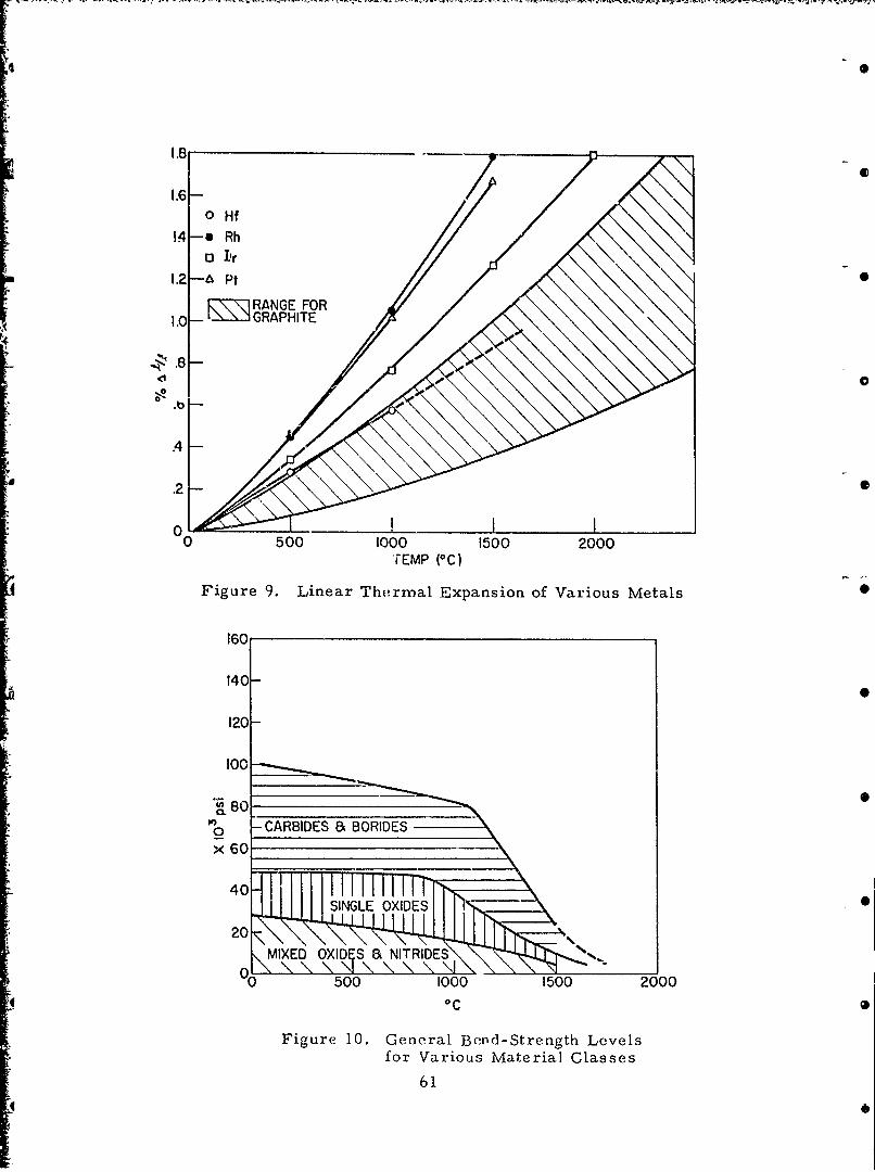
oHf14 *Rh
o3 I'r
RNEFOR1.0 RA PHIE
.2 00
1600
.404
.20
00
160
140-
120-
1000
x 60

The thermal conductivity will likewise vary with the coating method,primarily as a function of the density (porosity) and thp degree of orientationof the coating. Ranges of the thermal conductivity for various materialclasses are shown in Figure 11. The values at I100°C were in part obtainedfrom a recent study carried out at the Southern Research Institute(195). Nohigh temperature data could be found for the thermal conductivity of hafniumor the platinum group metals, except for platinum itself( 9 6).
0.60- WI-.
UIIJIAT ROOM TEMP <0.56 ROMcEMP5AT 1000 ° C U) 0
0.52 (n'Bo WBeO W a
00.22 T In
U)SW
LZ0.14 n I41 0
0.10 P "Jz
0.06 L'Hf
0D2k-
Figure 11. Thermal Conductivity of PotentialCoating Materials
The eutectic temperature for various oxide combinations are listed inTable 29. Many of the mixed oxides listed have melting points far below20000C and must therefore be excluded as possible high temperature coatingmaterials. For thermodynamic reasons, there are, of course, no eutectic'sbetween oxides aLd carbon or carbides. The eutectic temperatures of
*o@ . refractory metals with carbon have been determined by Nadler and Kempter( 9 7 ).Some of the investigated metals form carbides, and in those cases the metal-carbide and carbon-carbide eutectic (or peritectic) temperatures were alsodetermined. Their results are shown in Table 30 and 31. However, someof these temperatures (e. g. , the irioium-carbon e utectic) appear too high,probably because of insufficient contact with carbon and/or short ho!d-timesat high temperatures.
V- 62

Table 29. Liquidus Temperatures (°C) for Various Oxide Combinations
AZ0 3 BoO CaO CeOZ MgO SiO, ThOz TtO z ZrO2 Spinel Zircon
- A10 3 2050
BeO 1900 2530
CaO 1400 1450 2570
CeOz 1750 1950 2000 2600
MgO 1930 1800 2300 2200 2800
SiOz 1545 1670 1440 1700* 1540 1710- ThO2 '1750 2150 2300 2600 2100 1700* 3050
TiOz 1720 1700 1420 1500 1600 1540 1630 1830
ZrOz 1700 2000 2200 2400 1500 1675 2680 1750 2700
MgO. A12 03 1910 1720* 1850* 1700* 2030 1340 1750* 1600* 2140 2140*
ZrOz SiO z 1540 1650* 1400* 1700* 1500* 1680 1680* 1500 1680 1300 2420
* Approximate
Table 30. Minimum Solidus Temperaturesfor M-C Systems
Metal Metal CarbonMelting SolidusTemp. C Temp. oC
Pd 1552 1504±16Rh 1960 1694117Pt 1769 1736j13Ir-50 Rh 1932±17Ru 2250 1942+16Mo 2610 201:14Ir 2442 2296±16Nb 2415 2328±17Re 3180 2486±18W 3410 2732±22Os 3000 2732±22Ta 2996 290Z30
63
-0

Table 31. Eutect.c, Peritectic and CompoundMelting Temperatures
MeltingComposition Temp. 0C
- Nb + graphite Nb-NbzC eutectic 232&! 17Nb + 7.0 C Nb2C-NbC peritectic 3080 ± 35Nb + 11.0aC NbC-C eutectic 3220 + 40Ta + graphite Ta-TaZC eutectic 290Z ± 30Ta + 4. 0 C TazC-TaC peritectic 3500 - 50Ta + 8.0 'C TaC-C eutectic 3710 - 50NbC NbC m. p. 3480 ± 50TaC TaC m.p. > 3550MozC MoZC m.p. 2410 ± 15WC WC m.p. 2720 ± 20
aWeight per cent.
There are many further investigations of the solubility of metalsand/or carbon in refractory carbides and of phase diagrams of metalcarbide-carbon systems. Over 200 pertinent references are listed in the
L. Carbide Bibliography published by the Lawrence Radiation Laboratory(193).
Some refractory oxides, unless properly stabilized, undergotransitions at elevated temperatures which can be destructive enough torender the coating useless. The phase changes occurring in zirconia havebeen particularly well investigated. Pure zirconia exhibits one monoclinic,
*two tetragonal, and two trigonal modifications, depending on temperatureand method of preparation. Addition of from 5 to 15 per cent of CaO, MgO,or rare earth oxides results in a sixth (cubic) form, which does not undergophase transitions but unfortunately has a very high thermal expansion.Older work (t- 1954) on zirconia and its .tabilization has been reviewed byRunck(19 . The kinetics of the reversible monoclinic-tetragonal transition
* at 1155°C has been investigated by Sukharevskii(199). Mumpton and Roy( ° ° )have shown that the addition of 2 per cent ThOz to ZrOz lowers this transitiontemperature by approximately 150'C. Hafnia also undergoes a monoclinicto tetragonLl phase transformations, but at a higher temperature (1500' to1600c) VZ°1). Godina and Kelert z2 0 2 found that the stability of solid solutionsof CaO in ZrOz or HfO2 was higher than that of solid solutions with MgO.
*Q The stability also increased with increasing purity of the ZrOz or HfOZ usedin preparing the solid solutions.
It has been reported that single crystals of BeO do not undergophase inversion upon heating(203). However, sintered BeO suffersdestructive decrepitation at 20500C, even when heated very slowly(<2°C/min.
* through the critical temperature range( Z°4). Later X-ray work h s hownthat there is a reversible phase transition in BeQ at 20500C(2Z s), (206T. Thetransition probability is discussed by Murthy(ao7).
64

IV. CONCLUSIONS
A. Previous Work on Oxidation Protective Coatings for Graphite.
Much effort has been devoted to controlling the oxidation of graphite -by the use of surface coatings, impregnants, and oxidation retardants, Inthe past, technical approaches to the problem have involved, mainly,detailed studies of methods of applying coatings to various graphitesubstrates and a somewhat qualitative means of testing the coating. Themost satisfactory coating for graphite, developed by this approach, is siliconcarbide, which protects graphite for substantial time periods to about -16500 C. No systematic effort to determine the principles leading toimproved coating systems has been put forth. The literature contains noindication that a significant effort has been expended in developing teststandards which will identify and evalaate the various desirable characteristicsof these materials.
B. Diffusion through Protective Coatings
The rate of diffusion of oxygen and carbon through various materialscan be obtained from self-diffusion coefficients, oxidation, or carburizationconstants, or similar data if the mechanism of the diffusion is understood.Data in the literature indicate that oxygen permeability is lowest in themetals between tungsten and gold in the periodic table, and that diffusionthrough the oxides is greater than for these metals. Diffusion constantsshould be smaller for the more compact and more refractory oxides. Therate of diffusion of carbon through refractory metals is similar to thatthrough carbides. In addition, diffusion constants for carbon throughcarbides are expected to be greater than for diffusion of oxygen throughoxides. No real knowledge is available for diffusion of carbon through borides.Since the borides are more stable than the carbides, they have promiseof being better carbon barriers. It should be emphasized that studies ofpermeability under conditions that can be directly related to the actualcoating are most necessary. There are probably no cases where the presentdata can be extrapolated with any real accuracy to the conditions where acoating will operate.
C. Volatility of Coating Materials
Existing data on the vapor or dissociation pressure of most refractorysingle oxides appear adequate. However, if one considers a coating whichmay be subjected to an environment containing water vapor, the enhancementof the volatility of oxides in the presence of water vapor needs to beinvestigated for any prospective coating material. There are essentiallyno existing data on the vapor pressure of, and the gasecis species inequilibrium with, the mixed oxides.
65

The volatility of platinum group metals is very low; however, in thepresence of oxygen the volatility increases substantially. Rhodium andiridium appear to be the only refractory metals which are sufficientlyoxidation resistant to warrant their consideration as coating materials incontact with oxygen. Information concernir g the volatility- of theoe metalsin the presence of water vapor and in the presence of oxygen to tempera-tures in excess of 20000C is needed.
D. Chemical Compatibility
Several refractory carbides, borides, and silicides offer potentialcoating systems for graphite. The carbides include SrCz, ThC2, LaCz,4TaC:ZrC, 4TaC:HfC, ZrC, and HfC. Since all the carbides except ZrC,HfC, and the mixed Ta carbides hydrolyze, they appear less promisingat the outset. Further work is needed concerning the reaction betweencomp -ted refractory oxides on solid graphite shapes in order to determinethe utility of graphite-metal oxide composites. Also, the reactionsbetween selected metal carbides and the corresponding metal oxides needto be investigated in the absence of oxyger, as well as in its presence. Themost promising borides are ZrBz and HfB,; however, the stability of HfB2in the presence of graphite has not been investigated. Silicides of greatestpotentiality include those of Zr and Hf.
E. Mechanical Compatibility
: L"The available property data indicate that the oxides as a group will posethe most severe mechanical compatibility problems, primarily because ofhigh thermal expansion coupled with low strength and, except for BeO, lowthermal conductivity. The thermal expansion problem could ue somewhatmitigated by employing a more compatible intermediate layer, which, forchemical reasons, is required anyway. Even then, however, the oxide
a layer should be kept as thin as possible. a requirement that could be met* onl i if the oxygen diffusion through these materials is slow and if the oxides
are not volatile even in the presenct- of water vapor. Of the refractory oxides,HfO2 appears to be the most compatible with graphite. Most carbides andborides will probably be mechani.a-ly compatible with graphite. However,the oxidation protection afforded b these materials depends on the formationof an impervious outer oxide layer.
Of the platinum group metals, only irldirn t-azs a carbon-metal eutectic* temperature high enough to be usef'ii in direct contact with graphite. The
thermal expansion of iridium is somewhat higher than that of commerciallyavailable graphites, but a graphite mat--hir~g iridium could probably bedeveloped. Furthermore, the high strength and the high thermal conductivityof iridium reduce the thermal shock problem. Other platinum group metalshave substantially higher thermal expansion coefficients than iridium.Rhodium could possibly be used as an oxidation resiscant coating, with anintermediate layer to prevent the formation of the rhodium-carbon eutectic
66
.

and to mitigate the incompatibility in thermal expansions. Hafnium andhafnium carbide should both be mechanically compatible with graphite.Since HfO2 has the lowest thermal expansion of all crystalline refractoryoxides, this system appears to be particularly promising.
The mechanical and thermal properties of a coating may be expected tovary with the method by which the coating is applied. Although this conditionaffords the possibility of making a given coating system more mechanicallycompatible, it also makes impossible predicting accurately the degree ofcompatibility from the properties of the bulk materials alone. Ultimately,the mec1 anical compatibility can only be determined by experiments on theentire coating system.
667
46l

REFERENCES
I. Krier, C. A., "Coatings for the Protection of Refractory Metals fromOxidation, " DMIC Report 162, November Z4, 1961.
2. Private communication from J. Seldin, March 1964, Carbon Products"- Research Laboratory, Union Carbide Corporation.
3. Chem. & Eng. News 39:56-57 (November 13, 1961).
4. Refractory Composites Working Group Meeting, 16 June 1962, ValueEngineering Company.
5. Electrodeposition of Erosion and Oxidation Resistant Coatings forGraphite. Navy Dep't. Bureau of Naval Weapons, Contract No.N600(19)58317, 15 March 1963.
6. Mellors, G. W. and Senderoff, 6., "Electrodeposition of CoherentDeposits of Refractory Metals, " Electrochem. Soc. J., 110:180C(Aug., 1963).
7. Withers, J. C., et al,'Iridium Plating and its High TemperatureOxidation Resistance," Proc. AES 44, 124-9 (1957).
8. Rhoda, R. N., "Deposition of Several Platinum Metals from Molten
Cyanide Electrolytes, " J. Am. Electroplaters Soc. 49, 69 (1962).
9. Lamb, V. A., et al., "Electrophoretic Deposition of Metals,Metalloids, and Refractory Oxides, " Plating, Pp. 291-296 109 (1963).
1 10. Gutierrez, C. P. , et al., J. of Electrochem. Soc. 923-29, 109 (1963).
II. Roller, D., Summary of Second High Temperature InorganicRefractory Coatings Working Group Meeting, WADC TR 59-415June 1959, Pp. 81-83.
12. "Preparation of Protective Coatings by Electrophoretic Methods,"WADC
Technical Report 56-5ZI, ASTIA Document No. AD 119224.
13. Powell, C. F., Campbell, I. E., and Gonser, B. W., Vapor-Plating,John Wiley and Sons, Inc., New York (1955).
14. Blocher, J. M., Jr., et al., Chemical Vapor Deposition DMIC Report170 (4 June 1962).
15. Campbell, I. C., et al., "The Vapor-Deposition of Refractory Materials,96, No. 5, Pp. 318-33 (1949) Trans. Electro. Chem. Soc.
16. Blocher, Jr., J. M., and Campbell, I. E., -Carbide Coatings forGraphite, " Proceeding of the Second United Nations InternationalConference on the Peaceful Uses of Atomic Energy, Geneva (1958),A/CONF, 15/P/1428. 68

09,
REFERENCES (Cont'd)
17. Blocher, Jr., J. M., et al. ,'"Carbide Coatings on Graphite,"Report No.-I BMI-1200.
18. I. E. VAS, et al., ARL 63-188, "An Investigation of Methods of Usinga Graphite Resistance Heater with Air, " Princeton University,Oct., 1963.
19. Mazdiyasni, K. S., et al., "Synthesis and Pyrolysis of Metal AlkoxidesDocumentary, Report No. ASD-TDR-63-322, May, 1963.
20. Mason, C. R., et al., "Investigation of High Temperature ResistantMaterials, " Engineering Experimental Station, Georgia Institute ofTechnology, Contract NOrd-15701.
21. Huminik, John Jr., "Investigation of Oxidation and Erosion ResistantCoatings on Molybdenum, Tantalum, and Tungsten, " Summary Reportunder Contract DA36-034-ORD-3Z70RD, March 6, 1961.
22. Huminik, John Jr., "High Temperature Inorganic Coatings',' pp. 184-5,Reinhold Publishing Corporation, New York, 1963.
23. Ingham, J. S., and Shepard, A. P.,"'Mvetallizing Handbookl'EngineeringCompany, Inc., Wesbury, L. I., New York (1959).
24. Galli, J. R. et al., "Development and Evaluation of Rocket Blast and
Rain Erosion Resistant Composite Coatings Produced by Flame SprayTechniques, " WADC Technical Report 58-493, ASTIA 209913, Feb. ,1963.
25. "Basic Studies of Particle-Impact Process ;or Applying Ceramic andCermet Coatings, " D. G. Moore, Project Leader, Enameled MetalsSection, National Bureau of Standards, work under an Air ForceContract.
26. Magoteaux, 0. R. et al., "Flame-Sprayed Refractory Coating forHeated Graphite Molds, " TID-(Z86 National Lead Co., April 5, 1960.
27. "Development and Possible Applications of Plasma and Related High-- Temperature Generating Devices, " Report MAB-167-M, Materials
Advisory Board, ASTIA 242334, August 30, 1960.
28. Mash, D. R., et al., "Process Variables in Plasma-Jet Spraying,paper presented at AIME Symposium on Plasma Arc Applications to
-* Metallurgy, Western Metals Congress (March 23, 1961).
29. Stetson, A. R., et al., "Plasma Techniqiies for Spraying Toxic andOxidizable Materials, " paper presented AIME Symposium on PlasmaArc Applications to Metallurgy, Western Metals Congress (March 23,1961).
30. Kramer, B. E. , et al., "The Effect of Plasma Deposition on theStability of Nonmetallic Materials, " Final Report under Contract NO60-6076-C (April, 1960 - May, 1961).
31. "Oxidation-Resistant Coatings for Graphite, " Technical DocumentaryReport No. WADD TR 61-72, Vol. 34, June, 1963.
69

REFERENCES (Cont' d)
32. Huminik, John Jr., "High Temperature Inorganic Coatings,pp. 161, 178, Reinhold Publishing Corporation, New York,1963.
33. McGeary, T. C., "Detonation-Gun," Machine Design, Aug. 31,1961, pp.. 87-90.
34. Bergeron, C. G. , "Protective Coatings for Refractory Metals,WADC TR 59-526, Part II.
35. White, A. E. S. , et al., "Refractory Coatings on Graphite withSome Comments on the Ultimate Oxidation Resistance of CoatedGraphite, " Part I, British Ceramic Research AssociationSymposium on Special Ceramics, July 11, 1962.
36. Chown, J., et al., "Refractory Coatings on Graphite with Some
Comments on the Ultimate Oxidation Resistance of CoatedGraphite,"1 Part II, British Ceramic Research Association
*Symposium on Special Ceramics, July 11, 1962.
37. Chown, J., et al., "Refractory Coatings on Graphite with SomeComments on the Ultimate Oxidation Resistance of CoatedGraphite, " Part III, British Ceramic Research AssociationSymposium on Special Ceramics, July 11, 1962.
38. Shaffer, P. T. B., "An Oxidation Resistant Boride Composition,
American Ceramic Soc. Bulletin, Vol. 41, pp. 96-99 (1962).
* 39. Paprocki, S. J., et al., "Gas Pressure Bonding," DMIC Report159, 25 September 1961.
40. Fast, J. D., Phillips Technical Review 6, 365 (1941).
41. Barrer, R. M. , "Diffusion in and through Solids, " CambridgeUniversity Press, London (1941).
42. Rosenberg, A. J. , J. Electrochem. Soc. 107, 795 (1960).
43. Moore, W. J., and Selikson, B., J. Chem. Phys. 19, 1539(1951). Also see Erratum, J. Chem. Phys. , 20, 9"27 (1952).
44. Loeb, L. B.. "Kinetic Theory of Gases," McGraw Hill, NewYork (1934).
45. Stearn, A. E. and Eyring, H., J. Phys. Chem. 44, 955 (1940).
46. Rhines, F. N., "Atom Movements, " American Society for Metals,Cleveland, 1951, p. 174.
47. Oishi, Y. and Kingery, W. D., J. Chem. Phys. 33, 480 (1960).
70

REFERENCES (Cont'd)
48. Hayes, D., Budworth, D. W., and Roberts, J. P., Trans. Brit.Cer. Soc. 62, 507 (1963).
49. Fryer, G. M., Budworth, D. W., and Roberts, J. P., Trans. Brit.Cer. Soc. 62, 525 (1963).
50. Edwards, H. S., Rosenberg, A. F., and Bittel, J. T., Report No.ASD TDR-63-635, July, 1963, Contract No. AF 33(657)-8470.
51. Austermann, S. B., and Meyer, R. A., NAA-SR-7637, ContractAT (1I-I)-GEN-8, 30 November 1962.
52. Douglass, D. L., "Conference on Corrosion of Reactor Materials,"AIEA, Salzburg, June, 1962.
53. Kubaschewski, 0., and Hopkins, B. E., "Oxidation of Metals andAlloys, " Butterworths, London (1962).
54. Peterson, N. L., WADD TR 60-793 (Contract AF 33(616)-7382).
55. Few, W., and Manning, G., J. Metals 4, 271 (1952).
56. Smithells, C. J. , "Metals Reference Book," Butterworths, London(1955).
57. Raub, E. , and Plate, N., Z. Metal Kunde 46, 328 (1955).
58. "High Temperature Materials Program Progress Report No. 13,Part A," GE-NMPO QEMP-13A, Contract No. AT(40-I)-2847,31 July 1962.
59, Norton,F.J., J. ApplPhys. 29, 1122 (1958).
60. Johnson, F.M.G., and Larose, P., J. Am. Chem. Soc. 49, 312 (1927).
61. Dietzel, A. , and Goenen, M. , Glastechnische Berichte 32, 48 (1959).
62. Rhip, D. W., Symposium Scie. Fusion Vene, Brussels (1958),Pp. 677-84.
63. Dravnieks, A., J. Electrochem. Soc. 100, 95 (1953).
64. Nicholas, M. G., Prantis, A., Dickinson, D. C. , and Whitman, C. I.
ASD-TDR-62-z05, Contract AF33(616)-8175 (June, 1962).
65. Dickinson, C. D., and Nicholas, M., Report No. ASD-TDR-62-205,Part II, Contract AF 33(616)-,8175, June, 1963.
. 66. Gulbransen, E. A., and Andrew, K.F., J. Electrochem. Soc. 97,383 (1950).
71
6?

REFERENCES (Cont'd)
6"s. Gulbransen, E. A., Trans. Electrochem. Soc. 91, 573 (1947).
68. Gulbransen, E. A., and Andrew, K. F., J. Electrochem. Soc. 98,241 (1951).
69. Johns, C. R. , and Baldwin, W. M., Jr., "'Metals Transactions,AIME 185, 720 (1949).
70. Davies, M. H. , and Birchenall, C. E., J. Metals 3, 877 (1951).
71. Gulbransen, E. A., and Andrew, K. F., J. Electrochem. Soc. 97,396 (1950).
72. Gulbransen, E. A., and Andrew, K. F., Trans. Am. Inst. Mining Met.Engrs. 185, 515 (1949).
73. Gulbransen, E. A., and Andrew, K. F., J. Electrochem. Soc. 104,334 (1957).
74. Paladine, A. E. , and Kingery, W. D., J. Chem. Phys. 37, 957 (1962).
75. Moore, W. J. , Elrisuzaki, Y., and Sluss, J. A., J. Phys. Chem 62,1438 (1958).
a ~76. Kingery, W. D., Hill, D. C., and Nelson, R. P., J. Am. Ceram.
Soc. 43, 473 (1960).
77. Lindner, R., Arkiv. Kemi 4, 381 (1952).
78. Oishi, Y,, and Kingery, W. D., J. Chem. Phys. 33, 905 (1960).
79. Lindner, R., and Parfit, G.D., J. Chem. Phys. 26, 182 (1957).
80. Austermann, S. B., NAA-SR-3170, Contract AT(11-1)-GEN-8,(December 15, 1958).
81. Austermann, S. B., NAA-SR-3170, 15 December 1958; NAA-SR-5893,I May 1961, Contract AT (11-1) GEN-8.
82. Austermann, S. B., Meyer, R. A., Swarthout, D. G., NAA-SR-6427,Contract AT-(11- 1) GEN-8; 15 September 1961.
* 83. Edwards, H. S., Rosenberg, A. F., and Bittel, J. T. , Report No.ASD-TDR-63-635, Contract No. AF 33(657)-8470, July, 1963.
84. Kingery, W. D., Pappis, J,, Doty, M. E, , and Hill, D. C. , J. Am.Ceram. Soc. 42, 393 (1959).
* 85. Lindner, R, , and Akerstrom, A. , Disc, Farad, Scc, 23, 133 (1957).
72
0

REFERENCES (Cont' d)
II 86. Lindner, R., and Akerstrom, A., Z. Phys. Chem. 6, 162 (1956).
87. Sucov, E.W., J. Am. Ceram. Soc. 46, 14 (1963).
88. Sucov, E. W., J. Am. Ceram. Soc. 46, 19 (1963).
89. Kubaschewski, 0., and Hopkins, B. E., "Oxidation of Metals and- Alloys, " Academic Press, New York (1962).
90. Debuigne, J., and Lehr, P., Comp. Rend. 256, 1113 (1963).
91. Quinn, C.M., and Roberts, M.W., Trans. Farad Soc. 59, 985 (1963).
92. Kofstad, D. , and Ruzicka, D. J., J. Electrochem. Soc. 110, 181 (1963).
93. McClaine, L.A., Report No. ASD-TDR-62-204, Part II, ContractNo. AF 33(616)-7472, May, 1963.
94. Mazdiyasni, K. S. , and Lynch, C. T., Technical Documentary ReportNo. ASD-TDR-63-322, May, 1963.
95. Levesque, P., and Cubicciotti, D., J. Am. Chem. Soc. 73, 2028 (1951).
96. Meyer, R.A., Austermann, S. B., and Swarthout, D. G., NAA-SR-6426,Contract AT (11-1) GEN-8, 30 October 1961.
97. Cubicciotti, D., J. Am. Chem. Soc. 72, 2084 (1950).
98. Gel'd, P. V., and Lyubimov, V. D., Poroshkovaya Met. P. 76(No. 4, 1963).
99. Samsonov, G.V., and Epik, A. P., Phys. Metals. Metallog. 14,144 (196?.).
100. Blocher, J. M., Jr., Ish, C. J., Leiter, D. P., Plock, L. F. , andCampbell, I.E., Battelle Memorial Institute, BMI-1200.
101. Kreimer, G.S., Efros, L.D., and Voronova, E.A., Zhur Tekh.Fiz. 22, 858 (1952).
102. Pirani, M. , and Sandor, J. J. Inst. Metals 73, 385 (19A47)
103. Hansen, M. , and Anderko, K., "Constitution of Binary Alloys,"McGraw Hill, New York (1958) .
104. Glaser, F. W., J. Metals 4, 391 (1952).
105. Nicholas, M. G., Prantis, A. L., Dickinson, C. D., and Whitman, C. I.,* ASD-TDR-62-205, "The Analysis of the Basic Factors Involved in the
Protection of Tungsten Against Oxidation."
73

REFERENCES (Cont'd)
106. Ackerman,R. J., and Thorn, R. J., Prog. Cer. Sci. 1, 39 (1961).
107. Drowart, J., DeMaria, G. and Inghram, M.,J. Phys.29, 1015 (1958);Drowart, J., DeMaria, G., Barns, R., and Inghram, M., J. Chem.Phys. 32, 1366 (1960).
108. Porter, R. , Chupka, W., and Inghram, M. , J. Chem Phys. 23, 1347, 2159- (1955); Kistemaker, J. , Babehowsky, T., and Boerboom, A. ,-Physica
28, 1155 (1962); Pelchowitch, I. , Phillips Res. Repts. 9, 42 (1954).
: 109. Chupka, W., Berkowitz J., and Inghram, M., J. Chem. Phys. 26, 1207
(1957); Panish, M. , and Reif, L. , J. Chem. Phys. 38, 253 (190-.
- 110. Porter, R. ,Schissel, P., and Inghram, M. J. Chem. Phys. 23, 339 (1955).
1i. Grjotheim, K., Herstad 0., and Toguri, J., Can. Min. Met. Bull. 602,396 (1962); Altman, R. , J. Phys. Chem. 67, 366 (1963).
112. Chandrasekharaiah, M. S., "Volatilities of Refractory InorganicCompounds," BNL-7454, Brookhaven National Laboratory, Upton,New York, September, 1963.
113. Shapiro, E., J. Am Chem. Soc. 74, 5233 (1952).
114. Hoch, M., and Johnston, H. L., J. Am. Chem. Soc. 76, 4833 (1954).
115. Ackerman, R. J., and Thorn, R. J., Argonne Nat'i Lab. Report No.5824 (19D5).
116. Darnell, A. J., and McCollum,", A., NAA-SR-6498.
* 117. Panish, M. B., and Reif, L., WADD TR-60-463, Part II, (Oct. , 1962).
118. Hoch, M., Nakata, 1I., and Johnston, H. L., J. Am. Chem. Soc. 76,2651 (1954).
119. Erway, N. D., and Seifert, R. L. , Electrochem. Soc. J. 98, 83-88(1951).
120. Grimley, R., Burns R. and Inghram, M., J. Chem. Phys. 33, 308(1960); Norman, J., Staley, H. and Bell, W., J. Phys. Chem--. 68, 662(1964).
121. Feast, M. W. Proc. Phys. Soc. 63, 549 (1950).
122. Raziunas V., Katz, S., Private Communication, 1964.
123. Hampson, R. F., Jr., and Walker, R. F., "Vapor Pressure of Platinum,Iridium, and Rhodium," J. Research Nat'l. Bur. Standards, 65A,289-95 (1961).
74

REFERENCES (Cont'd)
124. Alcock, C. B., and Hooper, G. W,, Proc. Royal Soc. 254, 551-61(1960)
125. Scha fer, H., Heitland, H. J., Z. Anorg. Allg. Chem. 304, 249(1960).
126. Cordfunke, E. H. P., Meyer, G., Rec. Tray. Chem. 81, 49S (1962).
127. Krier, C. A., Jaffee, R. I. , Journal of the Less Common Metals 5,411 (1963).
128. Hill, J. S., A]bert, H. J., Engelhard Industries Technical Bulletin 4,58 September, 19c3.
129. Fryburg, G. C., J. Chem. Phys. 24, 175 (1956).
130. Fryburg, G. C. , Petrus, H. M, J. Chem. Phys. 32, 622 (1960).
131. Mcani. K. , Harano, Y. , Bull. Chem. Soc. Japan 33 (2) 276 (1960).
13Z. Johnson, P. D. , J. Am. Ceram. Soc. 33, 168 (1950).
133. Komarek, K. L., Coucoulas, A., and Klinger, J., J. Electrochem.Soc. 110, 783 (1963).
134. Murator, F. Sh., and Novoselova, A. V., KokladyOkad. NaukSSSR129, 334 (1959).
- 135. Bockris, J. 0. M., White J. L., Mackenzie, 3. D., Editors,Physicochemical Measurements of High Temperature, Academic
* Press, Inc., New York (1959).
136. Coughlin, J. P., Bull. U. S. Min. 542 (1954).
137. Brewer, L., Chemistry and Metallurgy of Miscellaneous Materials:Thermodynamics, Ed. Quill. National Nuclear Energy Series IV-191B.
138. :Schulz, D. A., Higgsand, P. H., and Cannon, J. D., Vol. XXXIV,Oxidation-Resistant Coating for Graphite, WADD TR 61-72.
139. Kroll, W. J., and Schlechtor, A. W. , Electrochem. Soc. Trans. 93,247 (1948).
140. Prescott, C H. , Jr. , J. Am. Chem. Soc. 48, 2534 (1926).
141. Kutsev, V. S. Ormont, B. F., and Epelbunm, Dokjady Okad. Nauk.SSSR 104, 367 (1955).
4 142. Zhenlankin, V. 1., Kutsev. V. S., and Ormont. B. F., ZhuralNeorganisheskon Khimii 3, 1237 (1958).
'Not yet published.75

REFERENCES (Cont'd)
143. Zhelankin, V.1., Kutsev, V.S., and Ormont, B.F., Russian Journalof Physical Chemistry 35, 1288 (1961).
144. Prescott, C. H., Jr., and Hincke, W. B., J. Am. Chem. S-- 49,2744 (1927).
145. Nadler, M.R., and Kempter, C. P., The Reviews of ScientificInstruments 32, 43 (1961).
146. Moeller, T. , Inorganic Chemistry, John Wiley and Sons, Inc.,New York (1956).
- 147. Brewer, L., Chemistry and Metallurgy of Miscellaneous Materials:Thermodynamics, Ed. Quill. National Nuclear Energy Series IV-79B.
148. Campbell, I. E., Editor, High Temperature Technology, John Wiley andSons, N-w York (1956).
149. Geller, R. F., and Yvorsky, P. L., J. Research, Nat'l. Bur. Standards,34, 395 (1945).
150. Rossini, F.D., Wagman, D. D., and Evans, W. H., Circ. Nat'l. Bur.Standards 500, Feb. I (195Z).
151. Lambertson, W.A., Muellerand, M.H., Ginnzel, F.H., Jr., J. Am.Ceram. Soc. 36, 397 (1953).
152. Silverman, A., "Data on Chemicals for Ceramic Use, " National ResearchCouncil, National Academy of Science, Washington, D. C., 118, June (1949).
153. St. Pierre, P. D., J. Am. Ceram. Soc. 35, 188 (1952).
154. Dolloff, R. T., and Sara, R. V., WADD-TR 60-143, Pai ts II, III, IV,and V (1960 to 1964).
155. Berkowitz-Mattuck, J., Kinetics of Oxidation of Refractory Metals andAlloys at 10000 to Z0000C, ASD-TDR-6Z-Z03, Part II (March 1963).
156. Bartlett R. W., Wadsworth, M. E., and Cutler, I. B., Transactions ofthe Metallurgical Society of AIME 227, 467 (1963).
157. Brewer, L., and Haraldsen, H., J. Electrochem. Soc. 102, 399 (1955).
158. Glaser, F. W. , J. Metals 4, 391 (J95Z).
159. Steinitz, R., Binder, I., Moskowity. D., Trans. AIME, J. Metals 4,983 (1952).
76

REFERENCES (Cont'd)
* 160. Norton Tech. Bull. 515, Norton Co.. Worcester, Mass., Nov. (1951).
161. Moers, K., Z. Anorg. n. Allgem. Chem. 198, 262 (1931).
16z. Brewer, L., Sawyer, D. L., Dauben, C. H.. and Tampleton, D. H.,J. Am. Ceram, Soc. 34, 173 (1951).
163. Lafferty, J. M., Phys. Rev. 79, 1012 (1950).
164. Berezhnoi, A. So, Silicon and its Binary System, Consultants Bureau,New York (1960).
165. Samsonov, G. V., Akademiya Nauk Ukrainskoy SSR, '.'Silicides andTheir Uses in Engineering, " Technical Translation, FTD-TT-61-409(1962).
166. Schwarzkopf, P. , and Kieffer, R. , Refractory Hard Metals, TheMacMillan Co., New York (1953).
167. Robins, D. A., "Power Metallurgy," (1/2), 172 (1958).
168. Kieffer, R., and Benesovsky, F. , Iron and Steel Institute, SpecialReport 58, 292 (1956).
169. Samsonov, G. V., and Umanskiy, Ya. S., "Hard Compounds ofRefractory Metals, " Technical Translation TT-F-102, NationalAeronautics and Space Administration (June, 1962).
170. "Refractorv Molybdenum Silicides, " Bulletin Cdb-6, Climax Molyb-
denum Company, New York (January, 1956).
171. Krikorian, 0. H. , University of California, "High TemperatureStudies. I. Reactions of the Refractory Silicides with Carbon andwith Nitrogen; IL, Thermodynamic Properties of the Carbides;III. Heat of Formation of the 3ir State of C2 from Graphite," U. S.Atomic Energy Commission, UCRL-2888, AD-63120, ContractW-7405-eng-48 (April, 1955).
172. Cline, F., J. Electrochem. Soc. 106, 322 (1959).
173. Colton, D. E. , Nuclear Engineering 6, 324 (1961).
174. Robins, D. A., and Jenkins, I. , Plansee Proc. p. 187 (1955); ActaMetallurgica 3, 598 (1955),
175. Kingery, W. D. , Property Measurements at High Temperatures,John Wiley and Sons, New York (1959).
77

REFERENCES (Cont'd)
176. Krier, C. A., "Coatings for the Protection of Refractory Metals
from Oxidation," AD 271384 (DMIC Report 162), November 24,1961.
177. Pentecost, J. L, , "Coating Materials and Coating Systems," in"High Temperature Inorganic Coatings," Huminik, J., Jr., ed.,
- Peinhold Publishing Corp., New 'York (1963).
178. "The Graphite Engineering Handbook, " Published by Union CarbideCorporation, Figure 5A, 02. 04, New York (1962).
179. "The Graphite Engineering Handbook," Published by Union CarbideCarporation, Figure 5B. 02. 02, New York (1962).
180. "The Graphite Engineering Handbook," Published by Union CarbideCorporation, Section 5B. 02, New York (1962).
181. Wright, M. S., "Properties of Carbon and Craphite at High Tempera-tures," in "High Temperature Technology," Campbell, I. E., ed.J. Wiley and Sons, New York (1956).
182. Cacciotti, J. J. , "Graphite and Its Properties," General ElectricCompany, R58AGT591, July, 1958, Revised June, 1960.
183. Glasser, W., Few, W. E., Directory of Graphite Availability,ASD-TDR-63-853, September, 1963.
184. "The Industrial Graphite Engineering Handbook, " Union CarbideCorporation, New York, 1962.
* 185. Dull, R. B., Physical Properties of Some Newly Developed GraphiteGrades, WADD-TR:- 61-72, Vol. 26 and Appendices I, II and III,June, 1963.
186. JANAF Thermochemical Tables, The Dow Chemical Company.
-- 187. Wicks, C. E., Block, F. E., Thermodynamic Properties of 65Elements, Their Oxides, Halides, Carbides, and Nitrides, U. S.Bureau of Mines, Bulletin 605.
188. Goldsmith, A., Waterman, T. E., Hirschhorn, H. J., "Handbookof Thermophysical Properties of Solid Materials, " Revised Edition,
* Vol. I; Elements, Vol II; Alloys, Vol. III: Ceramics (includesoxides and mixed oxides), Vol. IV: Cermets, Intermetallic (includescarbides, borides, ana ntrides), Polymerics and Composites:The MacMillan Company, New York (1961).
78

REFERENCES (Cont'd)
I D189. Battelle Memorial Institute, "Refractory Ceramics of Interest in
Aerospace Structural Applications," A Materials Selection Hand-book, Hague, J. R., Lynch, J. F., Rudnick, A., Holden, F. C.,and Duckworth, W. H. , authors of Technical Documentary ReportASD-TDR-63-4102, October, 1963.
W 190. Campbell, I. E. , ed., "High Temperature Technology, J. Wileyand Sons, New York (1956).
191. Huminik, J., ed., "High Temperature Inorganic Coating, loc. cit.,
referenced in 5. 1.
192. A. D. 271, 384, loc. cit., referenced in 5. 1,
193. University of California, Lawrence Radiation Laboratory, SomePhysical, Mechanical, and Thermodynamic Properties of TransitionMetal Refractory Carbides, A Bibliography UCRL-7284, March, 1963.
* 194. University of California, Lawrence Radiation Laboratory, PhysicalProperties and Phase Diagrams of Ten Refractorv Oxides, ABibliography UCRL-6262, Pt. 2, July, 1962.
195. Southern Research Institute, The Thermal Properties of 26 SolidMaterials to 5000'F or Their Destruction Temperatures, ASD-TDR-62-765, January, 1963.
196. Krishnan, K. S., and Jain, S. C., Brit. J. Appl. Phys. 5, 426(1954).
197. Nadler, M. R., and Kempter, C. P., J. Phys. Chem. 64, 1468-71(1960).
198. Runck, R. G., in Campbell, I. E., ed., High Temperature Tech-nology, Chapter 3, John Wiley and Sons, New York (1956).
199. Sukharevskii, B. Ya., and Vishnevskii, I, I., Doklady Akad. Nauk,
SSSR. 147, 882 (1962).
200. Mumpton, F. A., Roy, R., J. Am. Ceram. Soc. 43, 234 (1960).
201. Baun, W. L., Science 140, 1330 (1963).
202. Godina, N. A,, Keler, E. K., Ogneupory 26, 426 (1961).
203. Levin, E. M., Rynders, G. F,, Dzimian, R. J,, Nat'l. Bureau ofStandards Rept. No. 1916 (July, 1952)
79

REFERENCES (Cont'd)
204. Austermann, S. B., Atomics International, NAA-SR-64281] (September 30, 1961).
205. Smith, D. K. Kline, C. F., Frechette, V. D., J. Nucl. Materials6, 265 (1962).
206. Baker, T. W., Baldock, P. J., Nature 193, 1172 (1962).
Z07. Murthy, N. S., J. Opt. Soc. Am. 53, Z98 (1963).
208. Dreger, L.H., and Margrave, J.L., J. Phys. Chem. 64, 1323(1960); 65, 2106 (1961).
209. Nadler, M. R., and Kempter, C. P., J. Phys. Chem. 64, 1468 (1960).
L
6
0
80
IQ.