
com www U.S. A. 8-59 . 1M · PDF filethe life and usefulness of this equipment by fol ... cuit...
28
· ·' .. � ) : � .� - '\ .. •, LOW VOLTAGE SWITCHGEAR INSTRUCTIONS TYPE L G CIRCUIT BREAKERS (MODELS D AND E) 1-T-E CIRCUIT BREAKER COMPANY • PHILADELPHlA 30, PENNSYL VANIA �· / P U.S. A 59 www . ElectricalPartManuals . com www . ElectricalPartManuals . com
-
Upload
hoangquynh -
Category
Documents
-
view
215 -
download
2
Transcript of com www U.S. A. 8-59 . 1M · PDF filethe life and usefulness of this equipment by fol ... cuit...

· · ' .. � ) : � .� .: -
'\
..
•,
LOW VOLTAGE SWITCHGEAR INSTRUCTIONS
TYPE L G CIRCUIT BREAKERS
(MODELS D AND E)
1-T-E CIRCUIT BREAKER COMPANY • PHILADELPHlA 30, PENNSYLVANIA �· /
PRINTED rn U.S. A. 8-59 1M www . El
ectric
alPar
tMan
uals
. com
www . El
ectric
alPar
tMan
uals
. com

IB-54(1,1
--:�cut� SreoKcr ........ r r.n�J·•rn�-�n: o·
•8, C)r::J........, SrcnoorG
�c·· N-,ounttnc L) (' ·• 1::: [' s
�·
-.·'¥"·-;� �;\�
· . ..... :-::-. ·''•
. ·�
?ho�o 19937 -R
www . El
ectric
alPar
tMan
uals
. com
www . El
ectric
alPar
tMan
uals
. com

. ' ' � IB-540
----------------------qv�
l
INSTRUCTIONS FOR TYPE LG CIRCUIT BREAKERS
MODELS D AND E
INTRODUCTION
These instructions apply to Type LG circuit breakers having serial numbers with the prefix D (Model D) or E (Model E).
Read these instructions thoroughly and carefully before installing or attempting to operate the Type LG circuit breaker. The operator can prolong the life and usefulness of this equipment by following these instructions.
After the circuit breaker is installed and operating properly. file these instructions in a convenient place with any other drawings or switchgear data pertaining to the installation.
The Type LG circuit breakers can be furnished as a two-pole, three-pole, or four-pole breaker which may be either manually or electrically operated, depending upon the application. A threepole, electrically operated circuit breaker is shown in Fig. 1.
APPLICATION
The Type LG circuit breaker is designed for use on circuits where the interrupting requirements approach the interrupting ratings shown in Table II, and where the continuous current requirements are as shown in Table I.
The Type LG circuit breakers may be used as a main circuit breaker for a system, as a bus-tie circuit breaker between sources of electrical power, and as a feeder breaker if the interrupting requirement and the continuous current requirements warrant it.
RATINGS
The Type LG circuit breakers can be furnished in the ratings listed in Table I.
TABLE I RATINGS
TyPe of Mounting
ENCLOSED "URELITES"
LIVE FRONT
DEAD FRONT
Continuous Ratlng Rating Amperes Volts
2000 to 6000 A-C 600 A-C 2000 to 5000 D-C 250 D-C
2000 to 6000 A-C 600 A-C 2000 to 5000 D-C 250 & 750 D-C 8000 to 10000 D-C 250 D-C 2000 to 6000 A-C 600 A-C 2000 to 5000 D-C 250 0. 750 D-C
The interrupting ratings for Type LG circuit breakers are listed in Table II.
TABLE II INTERRUPTING RATINGS
Interruptinq TyPe of Continuous Rating Ratinq Operation Amperea Ampere a
2000- 3000 A-C or D-C 75.000 ELECTRICAL 4000- 6000 A-C or D-C 100,000
8000-1 0000 D-C 100,000
MANUAL NOT TO EXCEED LIVE FRONT 4000 A-C. 5000 D-C 10,000
MANUAL NOT TO EXCEED DEAD FRONT 4000 A-C. 5000 D-C 50,000
RECEIVING. HANDLING. AND STORAGE
Each circuit breaker, before leaving the 1-T-E Circuit Breaker Company. is carefully inspected and tested for proper operation, and then it ;s crated by workmen who are experienced in the proper handling and packing of electrical equipment.
TRANSPORTATION DAMAGE
Immediately upon receipt of the circuit breaker, examine the crates to detennine if any damage or loss was sustained during transit. If injury or rough handling is evident, file a damage claim at once with the carrier and promptly' notify the 1-T-E Circuit Breaker Company. The 1-T-E Circuit Breaker Company is not responsible for damage of goods after delivery to the carrier. However, the company will lend assistance in securing any adjustment if notified of such claims.
HANDLING
Unpack the cirucit breaker as soon as possible after receipt. If unpacking is delayed, difficulty may be experienced in making a claim for damages not evident upon receipt.
Use care in unpacking in order to avoid bend-ing, breaking. or damaging any of the circuit breaker parts. Check the contents of each package against the packing list before discarding any packing material. If any shortage of material is discovered. promptly notify the nearest representative of the I-T-E Circuit Breaker Company. Information spec.fying the purchase number, crate number, and part numbers of the damaged or / missing parts should accompany the claim.
www . El
ectric
alPar
tMan
uals
. com
www . El
ectric
alPar
tMan
uals
. com
----� �----------IB-541)1 <ID )
.)
STORAGE
When a circuit breaker can be installed immediately in its permanent location. it is advisable to do so even though it will not be placed in service for some time.
If the circuit breaker can not be installed in its permanent location, and it is necessary to store the equipment, the following pr�cautions should be taken.
1. Uncrate the circuit breaker as described under HANDLING.
2. Store in a dean, dry place with moderate temperatures.
3. Cover with heavy wrapping paper to prevent dirt or foreign substances from settling on the movable parts and electrical contact surfaces.
DESCRIPTION
The Type LG circuit breakers are manually or electrically operated against heavy springs located back of the contacts and in the operating mechanism and linkage. During inspection and maintenance periods, electrically operated circuit breakers-may be closed manually by a removable maintenance closing bar. Pantograph or truck mounted circuit breakers should be either· in the "TEST" position or withdrawn from the switchboard. The circuit breaker contacts are opened by the opening springs when a roller latch is released either by pushing the manual .trip button or automatically by any trip device with which the breaker is equipped.
Basically, each pole consists of a main current carrying solid bridge protected by intermediate and arcing contacts. The complete pole, mounted in an individual frame or housing, is operated through a double-toggle system from either a manual operating handle or closing solenoid. The frame or housing encloses a direct-acting series trip device which is adjusted easily and accurately.
Multi-pole circuit breakers have the closing arms of all poles rigidly tied together by a horizontal insulated bar so that the poles move in unison. The tripping movement of any pole is communicated from the overcurrent trip coils to the latch mechanism through a horizontal bar. A single latch with trip-free mechanism is mounted in the pole unit which carries the operating arm or handle. A buffer is mounted in the upper part of the operating arm to absorb the momentum of the mechanism at the end of the opening movement.
For electrically operated breakers, the closing solenoid assembly is mounted on the lower portion of the circuit breaker panel. The auxiliary devices necessary for electrical operation are mounted on or adjacent to the solenoid.
MAIN CONTACTS
The movable bridge ( 43. Fig. 2) consists of a solid copper bar to which silver-alloy inserts are brazed. Two bridges, their associated springs and travel limiting pins, are assembled in a bracket to form a complete contact unit. One or more contact units may be attached to each bridge arm and are brought into contact with the upper and lower stationary main contacts by a force-multiplying system of toggles.
INTERMEDIATE CONTACTS
The stationary and movable intermediate contacts ( 4 and 47, Fig. 2) are faced with silver-alloy blocks and provide a secondary path for the current. These contacts should always open after the main contacts but before the arcing contacts.
ARCING CONTACTS
The stationary and movable arcing contacts ( 3 and 48. Fig. 2) are faced with silver-alloy blocks. The arcing contacts should always open last and close first. If the arcing contacts "make" after the the intermediate contacts, excessive burning of the main and intermediate contacts may result. In addition to opening last. the arcing contacts on all poles of the circuit breaker should open at approximately the same instant.
ARC CHUTE
The arc chute ( 1, Fig. 2) is an efficient form of the magnetic blowout structure, and is easily removed for inspection and maintenance of the contacts. The arc chute consists of an assembly of insulating barriers which confines the arc within a limited insulated area. Magnetic blowout irons placed on the outside of the arc chute side plates are magnetized as the arcing contacts open. The magnetic field thus set up forces the arc into the extinguishing chamber between the insulating barriers where the arc is cooled and extinguished.
On steel enclosed circuit breakers. a hooded barrier assembly is added which covers the entire top and sides of the arc chutes.
BUFFER ASSEMBLY
The buffer assembly ( 11, Fig. 2) is arranged so as to absorb the kinetic energy of the bridge arm assembly as it reaches the open position. The assembly consists of a buffer with pieces of brake lining on its upper and lower surfaces, and a crank that acts as a brake shoe. The force of the brake shoes is derived from a spring which is compressed by the impact from the bridge arm assembly.
www . El
ectric
alPar
tMan
uals
. com
www . El
ectric
alPar
tMan
uals
. com

� �5401
----------�\1.11--
..._
36
35
34
1 hcChute 2 Barrler 3 Mo<rU.Ie hcinq Contact -4 Mo<rU.1• Interm.dlate Contact 5 Jlrldqe Conduc:tinq Strip 6 Jlrldqe Arm 7 Jlridqe Arm Toqqle Link 8 Operatinq Link 9 Operatinq hm Toqqle Linlc
10 Operatinq hm 11 llu.lfer Aa.mbly 12 Com�ector Bu 13 VWu.al Indica lor Linlcaq• 14 Manual Trip Linlc.aq• I 5 'Escutcheon 16 Front Sb .. t or Door
�0�0. 0 0 0 0 0 ,....__�_ ©
@ ©
©
0 6 0
0
17 Sbun! Trip Device 18 Connector Rod 19 Control Relay 20 Return Sprinq (Outer) 21 Return Sprinq (Inner) 22 Sbaft 23 Throw-in Arm 24 Main Latch Roller 25 Main Latch 26 Mo.in Latch Sprinq 27 Kiclc-oH Pin 28 Hoole Triqg"r 29 Auxiliary Latch Plate 30 Auxiliary Latch 31 Trigqer Tripper 32 Hoole Triqqer Latch Plate
2
t7
te
19 20
22
33 Tripper Bar 34 Air Che<::le Vabre 35 Sol•noid Assembly 36 Dual Maqnetic OvercutTen! Trip Device 37 Op..ra ting Sprinq (Center) 38 Magnet 39 Operating Sprinq (Outside) -40 LoW'er Terminal 41 Lower Bridqe Contact 42 Bridqe Contact Braclcet 43 Bridge 44 Bridge Shim 45 Upper Bridge Co ntact 46 Upper Terminal 47 Stationary lnt.,rm•diate Cont.act 48 Stationary Arcing Contact
Fig. 2-Type LG Circuit Breaker, Eledrically Operated Side Sedion View
Dwq. S-13836
/
·.·'
.s .·.-www . El
ectric
alPar
tMan
uals
. com
www . El
ectric
alPar
tMan
uals
. com

IB-5401 fWW\ �--��-------------------)
/ OPERATING MECHANISM
The operating mechanism, as shown in Fig. 2 •.
of the circuit breaker is a system of links forming two toggles in series which provides high contact pressure with relatively small operating force. The bridge arm is pivoted near the panel and carries the bridge arm toggle link which is connected through a pair of horizontal operating links to the housing.
A second system of toggles is made up of a short operating arm toggle link which pivots on the pin common to the bridge arm toggle link and operating links and the pin through the inner end of the operating arm. Both systems of toggles approach center when the circuit breaker is closed. Springs from the operating arm toggle pin to the bridge arm pivot pin assist the contact springs in opening the circuit breaker.
Trip Free Construction
The circuit breaker operating arm and throw-in arm are connected by a compound latch which may be released during closing by any tripping device after the arcing contacts touch.
A roller on the throw-in arm is engaged by the main latch which pivots on the operating arm. The angle of the latch surface forces it away from the roller. This action is normally prevented by the auxiliary latch which pivots on the main latch and engages a latch plate secured to the throw-in arm.
The latch plate must be positioned so there is approximately 0.020 of an inch between the surface of the auxiliary latch and plate when the throat of the main latch is against the roller. The springs assist in engaging the latches, and stops are provided for limiting their movement. The circuit breaker is held in the closed position by the hook trigger which pivots on the throw-in arm. The hook trigger engages a latch plate which is bolted to the right-hand housing. The hook is released during the opening of the circuit breaker when the kick-off stud strikes the cam surface of the trigger.
The latch tripper is pivoted to the housing and carries the tripper bar which is actuated by the tripping device. The operation of any protective device therefore moves the tripper bar. Movement of the tripper bar disengages the latch which results in the circuit breaker tripping.
Therefore. the tripping action is as follows: (A) the tripper bar moves the tripper against the auxiliary latch and disengages it from the latch plate. (B) This causes the main latch to slip off the roller and the breaker opens. (C) The stud on the operating arm releases the hook trigger and allows the throw-in arm to be lifted to engage the latche�.
6
AUXll.IARY SWITCH
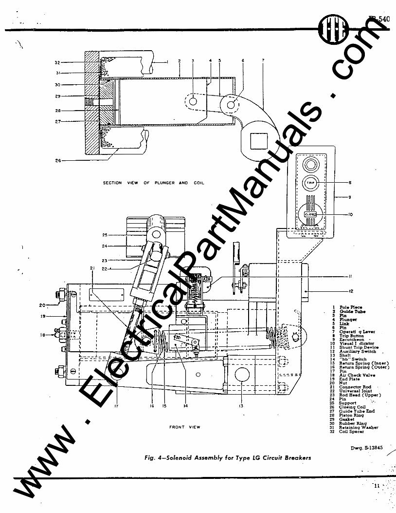
The auxiliary switch ( 12. Fig. 4) is used primarily to protect the coil of a shunt trip device by opening the trip coil circuit. The auxiliary switch may also be used to control indicating lamps and interlocking or alarm circuits.
The Type L auxiliary switch instruction bulletin number is listed in the bibliography at the back of this bulletin. Copies of this instruction bulletin will be furnished on request.
CONTROL RELAY
The Type R-14 control relay (19, Fig. 2). furnished only on electrically operated circuit breakers, has the heavy duty contacts required to control the relatively large current drawn by the solenoid closing coil.
The instruction bulletin number for the control relay is listed in the bibliography at the back of this bulletin. Copies of this instruction bulletin will be furnished on request.
RELAY CUT-OFF SWITCH
The relay cut-off switch ("bb" switch) ( 14, Fig. 4) is a two contact Type L auxiliary switch used to de-energize the pick-up coil of the control relay at the end of the solenoid plunger's closing stroke.
The instruction bulletin number listed for the Type L auxiliary switch in the bibliography at the back of this bulletin also applies to the "bb" switch.
INSTAllATION
The Type LG circuit breakers are adjusted, tested, and inspected before leaving the factory. However, it is possible that unusually rough handling during transit or severe operating conditions after installation may have loosened bolted parts or changed some of the adjustments. Refer to the MAINTENANCE and ADJUSTMENT sections for adjustments and procedures that may be required.
CAUTION: DE-ENERGIZE THE PRIMARY AND CONTROL CIRCUITS BEFORE INSTALLING THE CIRCUIT BREAKER OR ANY RENEWAL PARTS.
LOCATION
Indoor circuit breakers should be installed in a clean, dry place which is free from destructive action of acids, alkalies or gases. and where good ventilation can be secured. Open type circuit breakers should be mounted high enough to prevent injury to the operator during an automatic opening of the breaker, and it should be so located that it will be readily accessible for cleaning and inspection. Ample space must be provided above the circuit breaker to insure proper operation and to prevent damage to other equipment from arc conditions when opening under fault.
www . El
ectric
alPar
tMan
uals
. com
www . El
ectric
alPar
tMan
uals
. com

----------- � ® IB-5· ·}
MOUNTING
Individually Enclosed
The Type LG circuit breakers that are individually enclosed in a steel housing (Urelite) may be installed in any convenient location. Because of its weight. the Type LG Urelite is designed for floor mounting but it can be wall mounted if adequate structural steel supports are used. .
The Type LG Urelite includes a front enclosure which covers the operating mechanism and con· tact structure of the circuit breaker and a rear enclosure or pull box. The pull box is designed so that cutouts can be made in the sheet steel for the introduction of conduit, buses, or bus ducts.
For some applications, the pull box is omitted. This exposes the rear of the breaker panel. the studs, and all rear switchboard wiring. Under these conditions. the purchaser must make his own arrangement for enclosing the bus work and breaker studs.
Dead Front
Exclusive of Urelite, a dead-front mounting consists of a metal enclosed, dead-front switchboard. In this type of mounting. each circuit breaker is enclosed in an individual compartment having a flat front sheet or formed door for a front cover. The Type LG circuit breaker, in the switchboard compartment. may be stationary mounted. pantograph mounted. or truck mounted.
The instruction bulletin numbers applying to pantograph mounted and truck mounted circuit breakers are listed in the bibliography at the back of this bulletin. Copies of these instructions will be furnished on request.
Live Front In live front mounting. the insulating base of
the circuit breaker is stationary mounted to steel supports without benefit of any type of enclosure or prctective cover. However, in some installations, live front circuit breakers are mounted in enclosures or switchboards furnished by the purchaser.
ELECTRICAL CONNECTIONS
Before making any electrical connections. every precaution must be taken to see that all leads which are to be connected to the circuit breaker are de-energized.
All leads must be fastened securely to the terminals and tightly clamped to the connection studs. All joints must be clean. bright. and free from dents and burrs. All nuts on the current-carrying studs must be securely bolted against the terminal connection to obtain good contact. The nuts should turn freely on the studs and not be forced. If the joints are not made correctly, dangerous heating of the circuit breaker may result.
Cables and connections should be supported properly so that the circuit breaker is not subjected to unnecessary strains.
To avoid overheating of the circuit breaker. the connecting leads must have a current-carrying capacity at least equal to that of the current-carrying parts of the circuit breaker which in turn must be adequate for the maximum continuous current of the load.
Shunts for ammeters, resistors. or similar devices which operate at relatively high temperatures must be mounted far enough away from the circuit breaker so that they will not conduct heat to the breaker.
Control Wiring The control circuit wiring should be in accord
ance with the diagram accompanying the circuit breaker. A typical connection and schematic diagram for a-c application is shown in Fig. 3. Typical connection diagrams for d-e applications, or for a specific application may be obtained from the 1-T-E Circuit Breaker Company.
nNAL INSPECTION
The following inspections and tests should be made after the circuit breaker has been installed and all of its mechanical and electrical connections completed.
1. See that the circuit breaker is properly mounted and leveled on its supporting structure (panels, structural iron or steel. steel frame, etc.).
2. Close the circuit breaker slowly by hand, with the primary and control circuits dEH!nergized. noting whether the contacts are adjusted for correct alignment, and that good contact is made with the breaker closed.
3. Inspect all insulated wiring to see that no damage to the insulation has resulted during the process of installing the circuit breakers.
4. Test the wiring for possible grounds or short circuits.
5. See that all joints, whether bolted joints of copper bars or soldered (or clamped) joints made with wires or cables, are made correctly.
OPERATION
The manual and electrical operations are independent of each other. Therefore, the interruption of control power does not render the circuit breaker inoperable. and the circuit breaker may be kept in service as a manually operated device.
TRIP-FREE OPERATION
The Type LG c�cuit breakers are _me�hanically /
and electrically trip free so that the cucwt breaker mechanism may be tripped in any part of the clos-
7 www . El
ectric
alPar
tMan
uals
. com
www . El
ectric
alPar
tMan
uals
. com

--�5401 6W\ __ \IV __________ _ )
/ ing stroke by the operation of the tripping device. / / As soon as the arcing contacts touch under fault
conditions, the trip device will operate the tripping mechanism, releasing the tripping toggle, and allow the opening springs to return the contacts to the fully open position.
Circuit breakers equipped with undervoltage or reverse current trip devices are also trip free under undervoltage or reverse current conditions respectively.
D-C SOLENOIDS FROM A-C SOURCE
The dry plate rectifiers, used for conversion of alternating current to direct current, consist of a series of alternate treated copper and lead washers assembled on an insulated bolt.
It is characteristic of this type rectifier that, for a definite load, the d-e voltage will decrease slightly with age. This aging gradually disappears so that the output finally becomes nearly constant. To compensate for this change. it is customary to include in the circuit an adjustable resistance that may be reduced when necessary.
For higher. control voltages. the series resistor provides a means of compensating for aging and reduces the a-c voltaqe to the rating of the rectifier. On voltages above 220 volts. some resistance must be kept in the circuit to prevent damage to the
. ) rectifier. In case of a failure or excessive heating of any
unit of the rectifier, the whole group must be replaced because a new unit may have different characteristics than the unit being replaced and cause unbalanced loading to occur.
Rectifier aging should never cause failure on full control voltage. It will, however, increase the minimum voltage on which the circuit breaker will close. A small adjustment of the resistance should compensate for this condition.
Refer to the schematic diagram Fig. 3 when following the electrical closing procedure described in the following section.
ELECTRICAL CLOSING
To close the Type LG circuit breaker electrically. push the "CLOSE" button. This energizes simultaneously the pick-up coil (PC) and holding coil ( HC). The stronger of the two coils. the pickup coiL attracts the relay armature and closes contacts CR-1. CR-2, and CR-3. (Note: Contact CR-4 is closed when the relay is de-energized and remains closed when the armature is attracted to the pick-up coil maqnet ). This energizes the solenoid closing coil ( CC) and the solenoid plunger moves toward its closed position. At the end of the solenoid plunger's travel. the "bb" switch opens and de-energizes the pick-up coil (PC). The relay armature is then attracted by the magnet of the
J weaker or holding coil ( HC) and opens all the
8
CR contacts. The opening of contacts CR-2 and CR-3 de-energizes the solenoid closing coil (CC) and completes the closing cycle.
If the momentary "CLOSE" contact is held closed or if a control switch having a maintaining contact in the closing circuit is used, the circuit breaker will not attempt to reclose if it failed on the first attempt due to some fault. The reason for this failure to reclose is that the relay armature remains attracted to the magnet of the holding coil �ince it is still energized, thus preventing the CR contacts from closing. Therefore, a second attempt to close the circuit breaker can not be made until the "CLOSE" button is released or the control switch is turned to the "OFF" position which deenergizes the holding coil and closes the CR-4 contact.
The control relay is now in its normal de-energized position and will not function to close the circuit breaker until the "CLOSE" button is pushed. This non-repeat feature of the control r�lay prevents cyclic reclosing of the circuit breaker and assures that the momentarily rated pick-up coil receives only intermittent service.
ELECTRICAL TRIPPING
The Type LG circuit breaker can be electrically tripped by pushing the trip button mounted remotely from the breaker. The circuit breaker may also be tripped electrically by any of the following devices.
Shunt Trip Device
The shunt trip device is used to trip the circuit breaker electrically from a remote control point without regard to the load conditions of the circuit. The shunt trip devices furnished on the Type LG circuit breakers vary with the current rating, and with the type of overcurrent trip device (direct acting, series connected or current transformer trip).
The standard shunt trip device (I L Fig. 4) is furnished on the following:
1. D-C circuit breakers rated 6000 amperes and under.
2. A-C circuit breakers rated 3000 amperes and under having direct acting. series connected adhesion type dual magnetic overcurrent trip devices.
3. A-C circuit breakers rated 4000 amperes and under having either a Type OD-1 or Type OD-2 transformer overcurrent trip assembly.
The heavy duty shunt trip device is mounted on the circuit breaker panel. They are furnished on the following:
1. D-C circuit breakers rated 8000 and 10000 amperes.
2. A-C circuit breakers rated 5000 and 6000 amperes having either a Type OD-1 or Type OD-2 transformer overcurrent trip assembly.
www . El
ectric
alPar
tMan
uals
. com
www . El
ectric
alPar
tMan
uals
. com

IW1\ IB-5401
_.;..._ _________ \UJ ___ _
FRONT OF BOARD
COOE 6·03 AUX. SW.
I E3t�7y9EII o To To b 2 4 bs e O,o
es-c _L
r-------------1 I I I I I I
r-- ----I I
L--o O--+--o o--1 I
CONTROL BUS
I
es-T es-c I I 1 I
FURNISHED 1 I BY CUSTOMER I ·I
I I •------- --------------- -------- __ ...J
SCHEMATIC DIAGRAM
! I cs-f� �es-c 9 I L----'----------•
LEGEND
a - Auxiliuy switch contact dosed when circ-uit break�r contacts are closed.
b Auxlliary •witch contact cloaed when circuit breaker contact• are open.
bb
cc-Conl.act d osed when closinq solenoid plunqer
La in Don-op•r.ated poai.tion. Cloainq coil ( plunqer remain& In operated
poaitioc until circuit breaker opens).
CR Control relay. breaker clooinq. CR-1} CR-2
CR·3 CR-4 -
Closinq conrrol relay contacts-dosed when piclc-up coil ill enerqized.
Closinc; control relay conlact - open wh•n pick-up coil Is de-enerqized holdinq coil is enerc;i=ed.
CS.C - Cloae switch con tact.
CS-T - Remote trip awitch contact. HC - Cloainc; control relay holdinq coil.
OC - Overcurrent trip coil.
PC - Cloainc; control relay.pidc-up coil.
TC - Trip coil
NOTES
only and
1-Use B&S �1.( stranded roclcbectoc wire (Spec. lESE-PI) except u noted.
2--Adjust.able resistor to be used as adjustment for aqinq of rectifier on! y.
3-For two-pole breaker omit left·halld pole . .__ . Resistor when required by 220V. (25 Cyc.) or
380-600V. ( 2S & 60 Cyc. ).
' I 61 :--es-T 91
..
Dwg. S-13830 Fig. 3-Typical Diagram of Connection for Type LG Circuit Breakers
/
www . El
ectric
alPar
tMan
uals
. com
www . El
ectric
alPar
tMan
uals
. com
J.b-:>4U J. IW"'W\ __ \tV _____________ _ ) �/ The instruction bulletin number for the above
shunt trip devices is listed in the bibliography at the back of this bulletin. Copies of this instruction bulletin will be furnished on request.
Shunt trip devices furnished as a part of a transformer overcurrent trip assembly are mounted to the right of the overcurrent trip devices. This type of shunt trip is furnished on a-c circuit breakers rated 4000 amperes and over having an adhesion type dual magnetic transformer overcurrent trip assembly. For additional information on shunt trip devices which are mounted on the transformer overcurrent trip assembly. refer to the instruction bulletin listed in the bibliography at the back of this bulletin on adhesion type dual magnetic overcurrent trip devices.
DUAL MAGNETIC OVERCURR.ENT TRIP DEVICE-ADHESION TYPE
The dual magnetic overcurrent trip device (36, Fig. 2) combines an oil film time delay device having inverse time characteristics with an instantaneous trip element. The device provides overload protection with instantaneous short circuit protection. The standard range of overcurrent tripping value is 100 to 200 per cent of the continuous ampere rating of the circuit breaker.
The instruction bulletin number for the dual magnetic overcurrent trip assembly is listed in the bibliography at the back of this bulletin. Copies of this instruction bulletin will be furnished on request.
TRANSFORMER OVERCURRENT TRIP ASSEMBLY
The transformer overcurrent trip assembly is mounted on the solenoid assembly for electrically operated circuit breakers. and panel mounted for manually operated circuit breakers. The overcurrent devices furnished. depending on the circuit breaker application. may be the adhesion type dual magnetic overcurrent trip. Type OD-1 dual overcurrent trip. or Type OD-2 dual selective overcurrent trip. The overcurrent devices are actuated by the secondaries of current transformers which mav be mounted either on the load studs at the rear of the breaker panel for stationary mounted circuit breakers or in the primary bus for .drawout mounted circuit breakers.
Transformer overcurrent trip assemblies using adhesion type dual magnetic overcurrent trip devices are furnished on a-c circuit breakers rated 4000 amperes and over.
Transformer overcurrent trip assemblies using Type OD-1 dual overcurrent trip devices or Type OD-2 dual selective overcurrent trip devices are furnished on a-c circuit breakers rated 2000 amperes and over.
The instructions for transformer overcurrent trip J assemblies with adhesion type dual magnetic
10
overcurrent trip devices are included in the dual magnetic overcurrent trip device (adhesion type) bulletin listed in the bibliography in the back of this bulletin. Instructions for transformer overcurrent trip assemblies with dual magnetic overcurrent trip devices (displacement type) are included in the Type OD-1 and OD-2 overcurrent trip device bulletin listed in the bibliography. Copies of these bulletins will be furnished on request.
Undervoltage Trip Device (A-C and D-C)
The undervoltage trip device is a combination of an undervoltage unit and a spring trip mechanism. The operating coil of this device is responsive to a decrease in voltage below a predetermined value of main circuit voltage. The dropout voltage, which is not adjustable, is approximately 30 to 60 per· cent of the circuit voltage.
When it is required that the circuit breaker remain closed for a short interval following a voltage failure, an adhesion type time delay device is added. This device delays the operation of the undervoltage trip device for approximately 3 sec· onds at no voltage.
The instruction bulletin number for the undervoltage trip device is listed in the bibliography at the back of this bulletin. Copies of this instruction bulletin will be furnished on request.
MANUAL CLOSING
Manually operated dead front circuit breakers having a formed front door or Urelite mounted breakers use a side rotating handle. To close the circuit breaker. rotate the handle to the left with enough force and spe·ed so that the contacts close smartly without having the parts slam against their stops.
Manually operated live front circuit breakers or dead front breakers having a flat front sheet are furnished with a spade handle. To close the circuit breaker. lift the spade handle until the latches engage and then· press down until the contacts close.
Electrically operated circuit breakers may be manually closed by placing the maintenance bar in the socket provided in the universal joint support. To close the circuit breaker. press down until the contacts close.
MANUAL T�PING
To manually trip the circuit breaker. push trip button ( 8. Fig. 4).
MAINTENANCE The safety and successful functioning of the
connected apparatus depends upon the proper operation of the circuit breaker. Therefore. it is recommended that a maintenance program be established that will provide for an inspection of the
www . El
ectric
alPar
tMan
uals
. com
www . El
ectric
alPar
tMan
uals
. com
IW'h IB-540
-----------\1.17�
SECTION VIEW OF PLUNGER ANO COIL
0
16 15
FRONT VIEW
Fig. 4-Solenoid Assembly lor Type LG Circuit Breakers
1 2 3 4 5 6 7 8 9 10 11 12 13 14 15 16 17 18 19 20 %1 22 23 24 25 26 27 28 29 30 31 32
Pole P1--=GuJde 'fube P!..D PlWI.qft' Linlt Pin Operatinq !.eYer Trip Button E.ecutch.-on -Visual Indicator Shunt Trip DeTice Auxili.ary Switch Shaft "bb"" Switch
Return Sprinq (Inner) �turn Sprinq (Outer)
Air Checlc Va!Te End Plate Nut Conn�orRod Unh·eraal Joint Rod Head (Upper) Pin Support Cloainq Coil . Guide Tube End Platon Rinq GaU:et Rubber Rinq Retaining W&Aher Coil Spacer
Dwq. 5-13845 /
www . El
ectric
alPar
tMan
uals
. com
www . El
ectric
alPar
tMan
uals
. com
IB-5401 � ---=---\IV�----------
) circuit breaker at least once every six months and // immediately after operating to interrupt a fault.
J
CAUTION: TRIP THE CIRCUIT BREAKER AND DE-ENERGIZE THE PRIMARY AND CONTROL CIRCUITS BEFORE MAKING ANY INSPECTIONS, ADJUSTMENTS. OR REPLACEMENT OF PARTS.
CONTACTS
In general, any dirt or grease on the contacts should be removed by wiping them with a cloth saturated with carbon tetrachloride. Discoloration of the contact surfaces is not harmful. The dark brown tarnish that often appears may be removed with silver polish.
Mai:l Contacts
The main contacts should not show any signs of serious burning. If they do, the arcing and intermediate contacts may be in bad condition, the circuit breaker may be opening at currents beyond its interrupting capacity, or the contacts may be out of adjustment. Check for correct contact adjustment as described under ADJUSTMENTS.
Intermediate Contacts
) A slight amount of pitting is to be expected and - will not interfere with the operation of the inter
mediate contacts. Occasionally it may be necessary to remove small burrs with several light wipes of a fine file. Always follow the contour of the contacts and do not attempt to entirely eliminate the pitting. Contact overlap must be maintained, that is. the contacts must open well after and close before the main contacts. Prevent any filings from falling into the mechanism by covering it with a cloth. After filing the contacts, carefully remove the cloth and blow out any dust or particles that may have fallen into the mechanism with low pressure. dry air.
Arcing Contacts
A moderate amount of pitting is to be expe'::ted and will not interfere with the operation of the arcing contacts. It is seldom advisable to file or smooth down the arcing contacts. Severely pitted or eroded contacts should be replaced and the contact sequence carefully checked.
COIL REPLACEMENT
Solenoid Closing Coil
On some Type LG circuit breakers. it may be necessary to remove some of the accessories
12
mounted on or adjacent to the solenoid assembly before proceeding to replace the closing coil.
Refer to Fig. 4 and. 1. Disconnect the closing coil leads. 2. Remove three socket head screws in end
plate ( 19). 3. Remove four nuts (20) and remove end plate
(19). gasket (29), retaining washer (31). and coil spacer ( 32 ). Do not remove plunger tube end (27), guide tube (2). or plunger ( 4).
4. Remove the solenoid closing coil ( 26 ) . Take care so as not to damage the guide tube ( 2 ).
After removing the closing coil. inspect gasket (29) for damage and replace with a new gasket if necessary. Also. inspect the guide tube (2) and remove any accumulation of dirt or oil.
Replace the closing coil and re-assemble the solenoid using the reverse of the above procedure. It may .be necessary to remove the air check valve ( 18) in order to properly "line up" the holes in the end plate. gasket. and plunger tube end.
After replacing the closing coil and any other accessories that may have been removed, check for short circuits, grounds. and correctness of wiring before operating the circuit breaker electrically.
·
ADJUSTMENTS'
The Type LG circuit breakers are adjusted. inspected, and tested before leaving the factory. However. it is possible that rough handling during transit or abnormal usage may cause a change in some of the adjustments. . The individual tripping devices may be adjusted as described in the respective tripping device bulletins listed in the bibliography at the back of this bulletin. CONTACTS
The upper and lower contacts of the bridge should bear against the contacts on the terminal blocks so that the contact springs are compressed 3/32 of an inch (maximum) in addition to their initial compression.
To determine the compression of the contact springs. slowly close the circuit breaker until the main contads just touch. Measure the distance from the bridge arm (6. Fig. 2) to the panel. Complete the closing operation and again measure the distance from the bridge arm to the panel. (This measurement should be taken at a point midway between the upper and lower contacts on the bridge). If the movement is less than the 3/32 inch (maximum) allowed. remove the contact bolts and insert a thin shim at point "A" Fig. 2. Tighten all bolts after making any adjustments.
www . El
ectric
alPar
tMan
uals
. com
www . El
ectric
alPar
tMan
uals
. com

� IB-54C
___________ \U1,____
.. .... ,�,: ... .
.... · . . ·
_.I• ' ·,-.: .
RENEWAL PARTS
It is recommended that sufficient renewal parts be stocked to facilitate proper maintenance and replacement of parts. The quantity of parts and items carried in stock should be based on the number of circuit breakers in service and previous operating service.
When ordering renewal parts. address the nearest Sales Office of the 1-T-E Circuit Breaker Company. Specify the type of circuit breaker. serial number. description of parts. and quantity required.
Title
These instructions do not purport to cover all details or variations in equipment nor
to provide for every possible contingency to be met in connection with installation, operation, or maintenance. Should further information be desired or should particular problems arise which are not covered sulficently for the purchaser's purposes, the maHer should be referred to the 1-T-E Circuit Breaker Company.
BIBLIOGRAPHY
Dual Magnetic Ov.ercurrent Trip Device-Adhesion Type
Bulletin No.
IB-5408
Shunt Trip Devices . . . . . . . . . . . . . . . . . . . . . . . . . . . . . . . . . . . . . . . . . . . . . . . . . . . . . . . . . . . . . . . . . . . . . . . IB-5405
Type OD-1 and OD-2 Overcurrent Trip Devices . . . .. . . . . . . . . . . . . . . . . . . . . . . . . . . . . . . IB-1003-0Dl & OD2
Type L Auxiliary Switch . . . . . . . . . . . . . . . . . . . . . . . . . . . . . . . . . . . . . . . . . . . . . . . . . . . . . . . . . . . . . IB-1003-AUX
Type R-14 Control Relay . . . . . . . . 1 • • • • • • • • • • • • • • • • • • • • • • • • • • • • • • • • • • • • • • • • • • • • • • • • • • • • • • • . • • • IB-5412
Undervoltage Trip _Devices . . . . . . .. . . . . . . . . . . . . . . . . . . . . . � . . . . . . ... . . . . . . . . . . . . . . . . . . . . .. . . . IB-5406
Type LG Pantograph Mc:>�t�d Circuit Breaker . . . . . . . . . . . . . . . . . . . . . . . . . . . . . . . . . . . . . . . . . . . . . IB-6000-L Type LG Truck Mounted Circuit Breakers . . . . . . . . . . . . . . . . . . . . . . . . . . . . . . . . . . . . . . . . . . . . . . . . IB-6000-L T
Key Interlocks on Type LG Pantograph Mounted Circuit Breakers . . . . . . . . . . . . . . . . . . . . . .. . . . . . IB-6000-lL
The above listed instruction bulletins can be obtained by requesting copies from the nearest Sales Office of the I-T-E Circuit Breaker Company.
13
/
www . El
ectric
alPar
tMan
uals
. com
www . El
ectric
alPar
tMan
uals
. com

www . El
ectric
alPar
tMan
uals
. com
www . El
ectric
alPar
tMan
uals
. com

I --
. INSTRUCTIONS FOR · .. .
TYPE LG CIRCUIT BREAKERS . . : .. , ··.
l·T-E CffiCUl'T BREA.JCOI COMPANY Printed in U. S. A..-:z.MIM
IB-1102-LG
�· .
: ... . .. ·
Super .. dea IB-1100-LI www . El
ectric
alPar
tMan
uals
. com
www . El
ectric
alPar
tMan
uals
. com

www . El
ectric
alPar
tMan
uals
. com
www . El
ectric
alPar
tMan
uals
. com
-�-!_1�07._.-L_G_�-----------------------��r-____ L_o_w __ v_o_L_T_A_G_E __ S_W_IT_C_H __ G _EAR _____
2
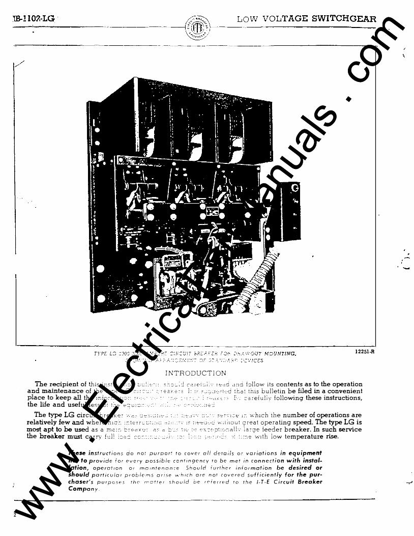
12251-R
INTRODUCTION The r�pient of thi_s 1:-:st�G=:i�r: ::;,:!:<:·:: �.--:=:_,:.; c-r.ri";::l:·. 1',-.,8 dnC bllow its contents as to the operation
and mallltenance of the tv;:,cc -'--"' c:�=: __ . : T-:o-:or -o:�s !· ;o.::J:Jc:'t·::c :r.a: th1s bulletin be Wed in a convenient place to keep all the mio���'2:1:::-:: ,, 1 ,- :-. • : .-:- � • 1 � .. . : ,:C.."""::- F.·. :::areiuliv following these instructions, the life and usefulness oi l."lc.- c.-:::u:�:� -,·:.· : .... :, :--·<�·:.;r'='::
The type LG circUJt breake; ·.·:c:c CJ-=-.�::;:,�..: : . : :·�,J--''- :::: _ ": s•.:-c-·:J:·c; i:-. v;hJch the number of operations are relatively few a.:J.d where h1c: �- : :-: t-2rrc: :;; ;;,c; c;; ,, . : ,., :o ::�.,a·.-c v:;ii10u t t;:reat operating speed. The type LG is most apt to be used as a me:::-. �:-E-r.K•.:: r.� c :::: ..: ' \1c· :•! c·x=:c-:J\:c<'1nlL· \a�:;re feeder breaker. In such service the breaker must carry full i:>o::: ::::.;:-_·:: . ...:� .:.,J·. -� : : - : : :: :,;,::··:..:·- -, ; ::::Je vnth low temperature rise.
These instructions rio not purport to cover all derails or variations in equipment nor to provide for every oossiblt: contin9cncy ro be met in connection with installation, operation or mamtenon�e Should iurthcr information be desired or should particular problems arise wh i ch ore not covered sufficiently for the purchaser's purposes the rratter should be rf'ierred To rhe 1-T-E Circuit Breaker Company.
-
www . El
ectric
alPar
tMan
uals
. com
www . El
ectric
alPar
tMan
uals
. com
l -·
c
6
LOW VOLTAGE SWITCHG EAR IB- 1 1 02-LC
INSTRUCTIONS FOR OPERATION AND
MAINTENANCE OF TYPE LG C I RCUIT BREAKERS
GENERAL CONSTRUCTION Basically each pole consists of a main current
carrying solid bridge, protected by secondary and arcing contacts. The bridge is removable and replaceable. The complete pole, mounted in an individual frame or housing, is operated through a double toggle system from either a manual operating handle or solenoid. The frame or housing encloses a direct-acting series trip device which can be adjusted easily and accurately.
Multi-pole circuit breakers, in which Fig. 1 shows a section view, have the closing arms of all poles rigidly tied together by a horizontal insulated bar so that the poles move in unison. The tripping movement of any pole is communicated from the overcurrent trip coils to the latch mechanism through a horizontal insulated bar. A single latch with trip-free mechanism is mounted in the pole unit which carries the operating arm or handle. A buffer is mounted in the upper part of the operating arm to absorb the momentum of the mechanism at the end of the opening movement. This device combines friction with spring action and provides shock absorbing effect in direct proportion to the speed of opening. The buffer completely eliminates the possibility of bouncing and reestablishing the arc.
The solenoid 'assembly is mounted on the lower portion of the circuit breaker panel. This assembly consists of a horizontal solenoid unit and several auxiliary devices. A shunt trip device for electrical remote tripping of the circuit breaker operates through an auxiliary switch. A control relay energizes the solenoid closing coil, and a "b b" switch operates the control relay.
SAFETY PRECAUTIONS
Be!ore making any adjushnents or replacements, make certain that all control circuits have been de-energized. If circuit breaker is drawout type mounted in a switchboard, withdraw breaker completely or to test position. If breaker is rigidly mounted, de-energize bus and disconnect cables from leads if there is a power source on the load side. Avoid injury that may be caused by unexpected operation. The heavy mechanical members operated by strong springs are restrained by sensitive latches.
MAIN CONTACTS
The main contacts, Fig. 1, consist of solid copper bars to which silver alloy inserts are brazed. Two bars, together with their associate springs and travel limiting pins are assembled in a bracket to
fo� a complete contact unit. One or more contact uruts may be attached to each bridge arm and are brought in contact with the upper and lower ternunals by a force multiplying system of toggles.
Adj ustments . . During the final closing of the brea�er, the mam contacts should bear against the termmal blocks so that the contact springs are compressed 3 32 of an inch in addition to their initial compression.
To determine the compression of the contact springs, slowly close the breaker until the main contacts touch then measure the distance from the bridge arm to the panel. Complete the closing operation and check the measurement of the bridge arm away from the panel. (This measurement should be taken at a point midway between the upper and lower contact blocks.) If the contact pressure is light, remove the contact unit bolts and insert a thin shim at point "a," Fig. l . Tighten all bolts after making any adjustments.
Maintenance. The main contacts should not show any serious burning. If they do, the arcing a:rri secondary contacts are probably in bad conditi or the circuit breaker is opening at curre� beyo�d its
,�n.te?'ur,ting capacity. A very slight bunung or p1tting does no harm. It is caused by the current path through the main contacts having a lower resistance than that through the secondary or arcing contacts.
The dark brown tarnish that often appears is silver sulphide, caused by coal smoke or gas in the air. Silver polish may be used if the surface is very dirty. We do not recommend the use of file or sandpaper on these contacts.
Overheating. The standards for circuit b realcers permit a temperature rise at the terminals of 30°C. above an ambient or room temperature of 40°C. An additional l 5°C. is permitted in enclosed switchgear.
On the Fahrenheit scale, a temperature rise of 54°F. above an ambient or room temperature of 1 04°F. is permitted .
Overheating is often caused by a loose connection between the circuit breaker and the bus, or a loose bolted or soldered joint at a cable terminal.
It is important not to let loose joints feed heat into a breaker. One way to detect a possible source of overheating is to take the millivolt drop between the contacts. Pointed terminals carrying a low voltage direct current are applied on each side -of the contacts and the drop in thousands of a volt is read on a millivoltmeter. This drop should not more than ten millivolts.
www . El
ectric
alPar
tMan
uals
. com
www . El
ectric
alPar
tMan
uals
. com

IB-1 1 02-LG
// SECONDARY CONTACTS
J
The secondary contacts (Fig. 1 ) in type LG circuit breakers provide a secondary path for the current and are of a blow-on construction. Secondary contacts should always open after the main contacts, but before the arcing contacts.
Maintenance. Slight burning of the secondary contacts is not harmful. Any slight burns may be removed by careful use of a fine file. When finefiling secondary contacts, their overlap must be maintained, that is, they must still open well after and close before the main contacts. If not, their usefulness is lost. Be careful not to let any filings get into the bearings or other parts of the breaker. Place a piece of cloth under the contacts and catch the filings in this cloth. If possible, blow out the breaker with dry air from an air hose after the work is done.
If the secondary contacts are badly burned away, the contacts should be replaced, and the sequence of contact to "make" and "break" carefully checked.
ARCING CONTACTS
The arcing contacts (Fig. 1 ) are also of blow-on construction and have a wiping action. Arcing contacts should always open last and close first when the breaker is opened or closed. If the arcing contacts make after the secondary contacts, excessive burning of the main and secondary may result . In addition to opening last, the arcing contacts on all poles of the breaker should open about the same instant.
Maintenance. It is seldom advisable to file or otherwise smooth down arcing contacts. A moderate amount of burning is to be expected, and does not interfere with proper performance. Badly burned arcing contacts should be replaced and sequence of contacts carefully checked.
ARC CHUTES
The arc chute (Fig. l ) used on type LG circuit breakers is an efficient form of the magnetic blowout structure. In this structure, magnetic vanes, mounted outside insulating barriers on e�ch side of the contacts, are magnetized upon opening of the arcing contacts, and the field set up by the current forces the arc into an extinguishing chamber. Thick plates in the chamber cool the arc and create a turbulent gas condition which forces a cooling draft across the arc core. Arcing time is shortened; the arc is confined; pressure of gases created by the arc is reduced, and heavy currents are safely handled in small space.
LOW VOLTAGE SWITCHGEAR
On steel enclosed breakers, a hooded barrier assembly covers the entire top and sides of the arc chute assembly.
It will be necessary to remove arc chutes to reach the arcing contacts. Before putting back the arc chutes, inspect them for any loose, broken or burned parts. Liners and side plates burn away in severe service, particularly on d-e circuits, and may need replacing. When the arc chutes are installed, be sure that they are firmly attached to the circuit breaker panel by their attaching studs.
OPERATING MECHANISM
The operating mechanism (Fig. 1) of the breaker is a system of links forming two toggles in series to provide a high contact pressure with relatively small operating force. The bridge arm is pivoted near the panel in the housing and carries a short toggle link which is also connected through a pair of horizontal links to the upper part of the housing.
A second system of toggles is made up of a second short link pivoted on the pin common to the two other links and the inner end of the operating arm. Both systems of toggles approach center when the breaker is closed. Springs, from the operating arm toggle pin to the bridge arm pivot pin, assist the spring of the contacts in opening the breaker qWC�y.
.
A single latah mechanism may be used for all poles. A tripper bar is provided to transmit the movement of any protective device to the main latch to trip the breaker.
Trip Free Construction. The breaker operating arm and the throw-in ann are connected by a compound latch which may be released by any tripping device at any time during closing (that the contacts are touching) .
A roller on the throw-in arm is engaged by the main latch pivoted on the operating arm. The angle of the latch surface forces it away from the roller. This action is normally prevented by the auxiliary latch pivoted to the main latch, which engages a latch plate secured to lugs on the throw-in ann.
This plate must be so positioned that, when the throat of the main latch is against the roller, there is a pproximately 0.020 inch between the surface of the auxili�ry latch and plate. The springs assist in engaging the latches, and stops are provided for limiting their movement. The circuit breaker is normally held in the closed position by the h ook trigger, pivoted on the throw-in arm. The hook trigger engages a latch plate which is bolted to the right hand housing. This hook is released during the opening of the breaker, when the kick-off stud on the operating arm strikes the cam surface of the trigger.
-
www . El
ectric
alPar
tMan
uals
. com
www . El
ectric
alPar
tMan
uals
. com

) •
" " / /
( . ) . -. '
LOW VOLTAGE S"(NITCHGEAR . . . . : =·-�. _ ... ..
INDEX
1 2 3 4 s 6 7 8 9
1 0 1 1 1 2 13 1 4 l S 16 1 7 1 8 1 9 2 0 2 1 22
� 0
0
0 0
ARC CHUTE BARRIER
DESCRIPTION
ARCING CONTACT CMovm<;r) SECONDARY CONTACT CMov•n<;r) BRIDGE CONDUCTING STRIP BRIDGE ARM BRIDGE ARM TOGGLE LINK OPERATING LINK OPERATING ARM TOGGLE LINK OPERATING ARM BUFFER SHOE BUFFER SLIDE CONNECTOR BAR MANUAL TRIP BUTTON TRIP BUTTON 1i CLOSE SWITCH CLOSING ARM RETURN SPRING MANU AL CLOSING SHAFT DEAD FRONT SHEET THROW-IN ARM M AIN LATCH ROLLER MAIN LATCH MAIN LATCH SPRING
0
0
BRACKET
INDEX
23 24 2S 26 27 28 29 30 3 1 32 33 34 35 36 37 38 39 40 4 1 42 43 44
DESCRIPTION
KICK-Off STUD HOOK TRIGGER AUXILIARY LATCH PLATE AUXILIARY LATCH TRIGGER TRIPPER HOOK TRIGGER LATCH PLATE TRIPPER BAll COIL POT SUPPOIIT DUAL MAGNETIC OVEIICUIIRENT TRIP OPERATING SPIIING (Center) MAGNET BRIDGE CONDUCTING TAIL OPERATING SPRING (Outaidel LOWER TERMINAL LOWER BRIDGE CONTACT BRIDGE CONTACT BRACKET BRIDGE BRIDGE SHIM UPPER BRIDGE CONTACT UPPER TERMINAL SECONDARY CONTACT CStohonary) ARCING CONTACT CStahonory)
Fig. 1 - - TYP£ LG CIRCUIT BR£AK£R �id.- Section v;,.,..
- IB-1 102-L<
D"-
www . El
ectric
alPar
tMan
uals
. com
www . El
ectric
alPar
tMan
uals
. com

IB- 1 1 02-LG
/ /
6
The latch tripper is pivoted to the housing, and carries the tripper bar which extends between the breaker poles and is actuated by the tripping devices. The operation of any protective device therefore moves the tripper bar. Movement of the tripper therefore will disengage the latch d uring closing or when closed.
The tripping action is therefore as follows: (A) the tripper bar moves the tripper ·against the auxiliary latch and disengages it from the latch plate, (B) this causes the main latch to slip off the roller and the breaker opens, (C) the stud on the o perating arm releases the hook trigger and allows the throw-in arm to be lifted to re-engage the latches.
MANUAL CLOSING
Side Rotating Handle. Grasp the handle, then rotate left with enough force and speed so that the contacts close smartly without having the parts slam against· their stops.
·
Maintenance Bar or Spade Handle. Lift the bar or handle until the latches engage, then press down until contacts close.
MANUAL TRIPPING
To manually trip the circuit breaker, push the trip button below the "close" button as shown in Fig. 2 . ELECTRICAL CLOSING
The direct current solenoid assembly as shown in Fig. 2 is located and mounted directly to the lower area of the circuit b reaker panel. Such devices as a control relay, shunt trip, auxiliary switch, and a . "bb" switch are attached to the solenoid housing and its support. The electrical connections for· these devices can be found in Fig. 3.
The complete solenoid has been assembled s o as to provide a direct electrical closing by mechanical linkage to the circuit breaker.
To Close Electrically, push the "close" button as shown in Fig. 2. Upon depressing this button switch, the "b b" switch opens, breaking the pick-up coil circuit of the control relay, which in turn energizes the solenoid operating coil.
To Trip Electrically, the shunt trip as shown in Figs. 2 and 4 provide a direct electrical means of tripping the breaker from some remote tripping point. Further description of this device can be found in section headed SHUNT TRIP. Coil Replacement. Refer to SAFETY PRECAU-
LOW VOLTAGE SWITCHGEAR
TIONS before attempting any replacement operation. Disconnect coil leads from binding posts. Remove end plate with plunger tube plug by removing four nuts from pole piece studs. Remove gasket, leaving tube and plunger in place. Allow six inches from end plate for removal clearance of coil. Care must be taken when removing coil to prevent damage to guide tube.
After removing the coil, inspect the guide tube, removing any accumulation of dirt or oil. Lubricate plunger with a light oil and wipe clean. G rease all pins, replace coil, attach coil leads, washer and gasket. Align guide tube plug with tube. Replace end plate, and four nuts with their lockwashers, and tighten securely.
After replacing coil, check the wiring for shorts, grounds or wrong connections before operating electrically. Refer to diagram of connections, Fig. 3.
OPERATION O F D C SOLENOIDS FROM AC SOURCE
The dry plate rectifiers used for conversion of alternating current to direct current consist of a series of alternate treated copper and lead washers assembled on an insulated bolt.
It is characteristic of this type of rectifier that, for a definite load, the d-e voltage will decrease slightly with age. This aging gradually disappears so that the output finally becomes nearly constant. To compensate for this change it is customary to include in the circuit an adjustable resistance that may be reduced when necessary.
For higher control voltages, the series resistor provides a means of compensating for aging and reduces the a-c voltage to the rating of the rectifier. On voltages above 220 volts some resistance must be kept in the circuit to prevent· damage to the rectifier.
In case of a failure or excessive heating of any unit of the rectifier, the whole group must be replaced, because a new unit and an old unit have dilierent characteristics and an unbalanced loading will occur.
Rectifier aging should never cause failure on full control voltage. It will, however, increase the minimum voltage on which the circuit breaker will close. A small adj ustment of the resistance should compensate for this condition.
CON TROL RELAY
The non-repeat control relay as shown in Fig. 2 has heavy duty contacts which are generally required to control the relatively large circuit drawn by the closing coil. Standard control switch contacts are not designed to handle the currents required for closing.
I "'
www . El
ectric
alPar
tMan
uals
. com
www . El
ectric
alPar
tMan
uals
. com

c_ .
; �.�. : 1 ;� ; ', � : : � :
� �
� � 8 d ::u ""i � 8 [l ::u C) � ttl ::u
§
1 !C ,_.. ' I
,'r& ') _ , , - - - - - - - - - , ('o"' � �/ '\� ' ' ... _ _ , .. _ .. ,
/ ... ��-i'::::.'\ ...... , \ ,' ,.a:o ,��, \ I ���' '�,\ \ I 111 � O I'I I • ,,, � ,. , I \ \:�\ ,:,;' \ '�' ... 0 ,!�"' /
\ ''�':::�::f-1-' ,' ,.- ., /--� \', ,, t()1 � ' ....... ,.,.., .... · � \, _ ,.' -- - - - \, ,
SIDE: VI£W
INDEX I PIN
O£SCRIJ>TtON
2 PLUNGE:R 3 LINK 4 OPERATING u:vt:JI s PIN 6 PLUNCE:R GUIDE: TUBE: 1 SOU:NOID OP£11A TING COD. 8 CASKE:T 9 PISTON RING
1 0 PLUNCE:R TUBE: !:NO I I COD. WASHER 1 2 CLOSE BUTTON 1 3 TRIP BUTTON 1 4 INDICATING LA MP ( Red )
\ . -r--
INDI:X O£SCRIJ>TtON INOE:X
I S INDICATING LA MP ( GrMa ) 29 16 CLOSING AJIM .RETURN SPRING (ln.aer ) 30 1 7 SHAll 3 1 1 8 CLOSING ARM RETURN SPRING (O...Ier ) 32 19 SWITCH ( b-b) 33 20 CLOSING ARM 34 2 1 PIN 3S 22 POU: PIECE STUD NUT :J6 23 ROD HEAD ( Lower ) 37 24 E:ND PLATE 38 25 AIR CHtCIC BAU 39 26 AIR CHOCIC VAl. vt 40 27 ADJUSTING SCREW 4 1 2t AIR CHOCJC VALVE SPRING 42
fROfiT VIE'«
DESCRIPTION
BUSHING CONNE:CTOR ROD ROD HI:AD (':jt:;.;> UNIVERSAL I PIN UNIVt'RSAL JOINT SUPPORT SHUNT TRIP UNIT AUXILIARY SWITCH CYUNDER SUPPORT R-14 CONTROL lti:LA Y POU: Pl£C£ PANEL BINDING POST con. U:ADS
· .......--
I
t;C 0 :a < 0
� G) 1:'1 Ul � 1-4 t-i 0 ::t= G)
�
� � .... 0 �
www . El
ectric
alPar
tMan
uals
. com
www . El
ectric
alPar
tMan
uals
. com
IB-1 1·02-LG
Inasmuch as this circuit breaker is electrically rip free, the breaker contacts may be tripped to
/ full open position at any point in the closing stroke of the solenoid. As long as the solenoid coil remains energized, the solenoid plunger will continue its motion to fully operated position regardless of whether circuit breaker contacts have been tripped open or not.
Further information for this control relay can be found in Bulletin 468 1 3 on request.
a
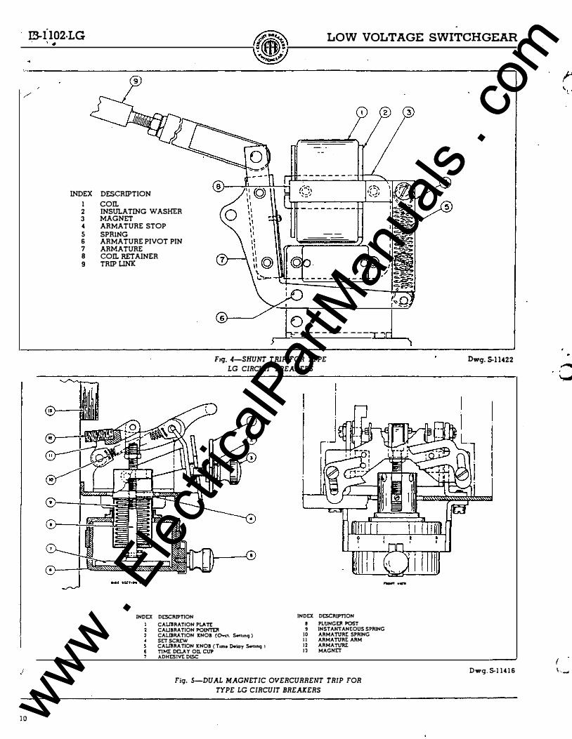
SHUNT TRIP
The shunt trip device shown in Fig. 4 is used to trip the circuit breaker electrically from a remote control point without regard to the load conditions of the circuit.
A U-shaped magnet is energized by a coil of fine wire. An armature is pivoted on one of the magnet poles, and is attracted to the other pole to trip the circuit breaker latch. A spring normally holds the armature against a stop, providing a fixed air gap from the magnet. During its final movement, the armature moves a trip linlc which disengages the latch.
An insulated auxiliary switch is in series with the shunt trip coil. This switch is closed when the circuit breaker is closed and breaks the circuit when the breaker opens. The circuit may be energized for any source of suitable voltage. A normally open push button is connected in series with the coil for remote tripping.
Coil Replacement. Refer to SAFETY PRECAUTIONS before attempting any replacement operation. The coil may be removed by withdrawing the armature pin and taking out the armature. An insulating coil retainer and washer hold the coil in position.
DUAL MAGNETIC OVERCURRENT TRIP
The dual overcurrent trip device shown in Fig. 5 is a combination of the instantaneous and time delay overcurrent trip features, providing moderate overload protection with instantaneous short circuit protection.
The device is mounted on the circuit breaker panel directly beneath the pole to whose current it responds. Since all poles are rigidly connected for opening and closing response of the tripping device on one pole affects the action of all poles.
On continuous overloads, an armature fastened to a pivoted arm is attracted to a magnet. After a predetermined time delay, adhesive disc separates from the adhesive surface of cup, allowing the armature, to which the disc connected by plunger post, to move upward and trip the circuit breaker. The standard range of overcurrent tripping value is from 1 00 percent to 200 percent of the continuous ampere rating of the circuit breaker.
LOW VOLTAGE SWITCHGEAR
Calibration Adj ustments. The air gap between armature and magnet is a maintained gap set at the factory. The range in calibration is obtained by varying the pull of springs when knob slides in slot of plate. To adj ust the overcurrent trip value, loosen knob and slicie to right or left until pointer is opposite desired current setting on calibration plate and tighten knob.
If the circuit breaker trips under starling loads, an increase in time delay setting is preferable to an increase in overcurrent setting. Time delay setting is govemed by the amount of surface area in contact between the adhesive disc and bottom of cup.
The lowest setting that will permit the circuit breaker to remain closed under normal conditions should be used. Zero gives instantaneous tripping and 3 indicates mcui.mum time delay.
An instantaneous trip spring is compressed to allow armature to trip the circuit breaker without the delaying action of the adhesive discs. At current approximately 12 times circuit breaker current rating a-c and 8 times d-e, spring is compressed by pull of armature. The armature may then move upward to trip the circuit breaker. Adj ustment for . instantaneous trip is made at the factory and should not be changed.
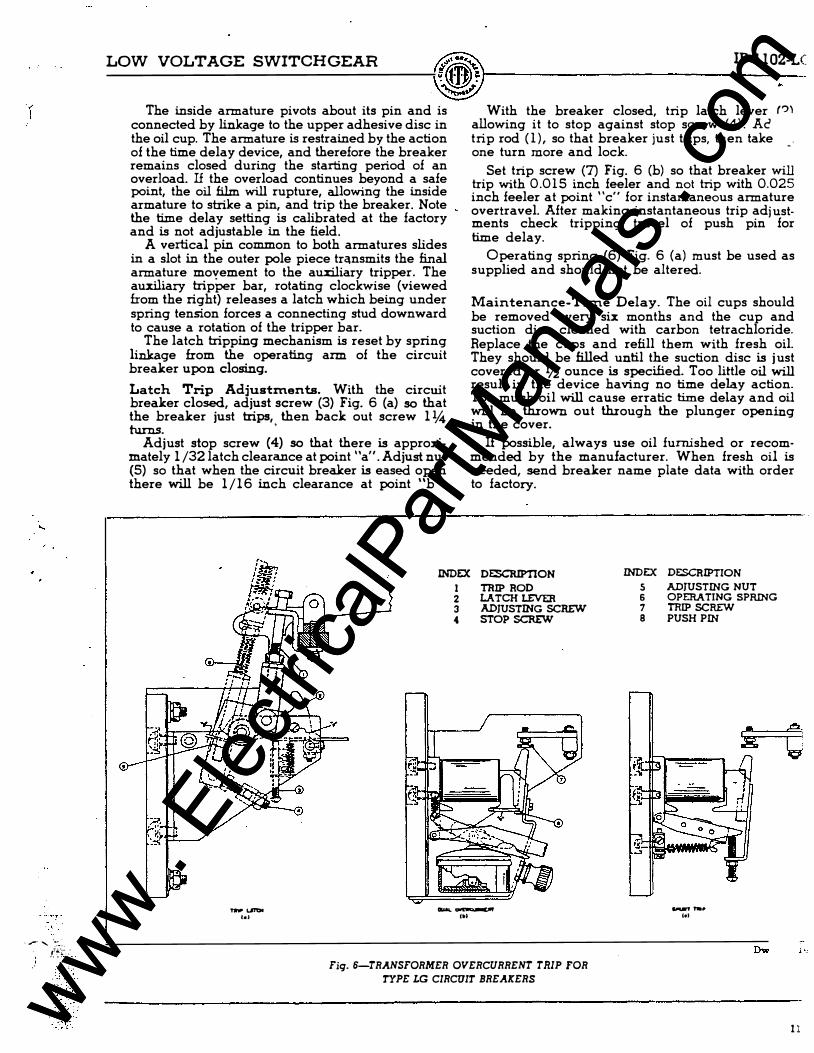
TRANSFORMER OVERCURRENT TRIP
The transformer ove:rcunent trip. device shown in Fig. 6 may be either instantaneous, or dual trip types. This device is standard on a-c breakers above 3000 ampere capacity and is actuated by the secondaries of current transformers usually installed on the load side rear of the circuit breaker . These devices are used for direct tripping of circuit breaker where relatively small power is required, or where a spring trip is used to disengage the circuit breaker latch. An adjustment is provided for changing the armature air gap so that the tripping currents may be varied over a 1 00 to 200 percent range. The armature is provided with an adjustable device for delaying the tripping action on momentary overcurrents.
The Dual Overcurrent Trip as shown in Fig. 6 (b) consists of a horizont3.l magnet core extending from its p:mel and is surrounded by a coil which is connected to a current transformer located back of the breaker panel.
At each end of the magnet core, pole pieces extending downward to two armatures, one straddling the other. Springs lift the inside armature at its pivot to prevent vibration on a-c currents. The outer end of the armature is adjustably supported and a calibration plate is marked in tripping currents.
The outside armature will trip the breaker instantaneously on approximately 1 2 times the full load current or on short.circuit. This armature pivots about its own pin and is independent of the time delay device.
I \..
·-
www . El
ectric
alPar
tMan
uals
. com
www . El
ectric
alPar
tMan
uals
. com

':J .. .
'l:�::·::f'l; . : � >' ::-
"'
� � � [;j s:z � :... O Q - ::u 0 :.., 0 � � 0 ::u -., :... () t;l o t:.J � Q � ::u q o _ c::: o t:i t; tu ...,
� g � .... ::tl � lll t>l
8
w
FRONT OF BOARD
I · I I )--· -3---� foe f� foe
re
I ..- - - - - - - _ _ _ _ _ _ _ .J I I I - - � - - - - - - - - - - - - - r - - ,
i ' I I I I I I I I I I I I I I
L I I ,------, ' I r'·i, �u111 1
l I Jl : �n.r r - - - - - - - - - - _J
-;,-
L I I ·;- f ":...�f .. htor J l
rl-r-1, ,..t,. .. r �,....& ,.- ., l t t t t S 1 4 t S t l t 7 t I ---+l-J.J.l.t.. f.t..f�4J. f.t.. _J -----.J . " Tt . • C�Sf0NfA1 GIIOUNO
CONII£CTION
CONTIIOI. IUS
SCHEMATIC DIAGRAM
LEGEND
" ( ' \u. f Cll·l
a-COPn'ACT Cl05III WIIDI ClftCIIIT IIIJ:Aitii iS ClOSID b-COPn'ACT Cl.OSID WHDI CIIICUrT lfttArtR IS OPDI
W.-COPn'ACT ct.ost:D WHDI CJ..OSII«l SOIL/iO!D IS IN NOHOPDIATm POSmON.
CC- CLOSINC COli. ( PLUHCCI REMAINS IN OPDIATtD POSITIOH UHTil. CIIICUrT IRtAKtft Of'tHS ).
Cft--ct.OSINC COPn'ROL liO.AY � \ ���:: ���ft8Jo.�.1 �OPn'ACT (ClOSUl WlltH Cft l O..OSIHC COH1ROL ftti..A Y CONTACT ! OP£H ONLY WlltH
PICt UP COIL IS Dt [H[flCIUD AND HOLDING COIL IS tHI:IIGillll l.
C$ · CONTROL SWITCH CS C-·COH1ROL SWITCH Clost COPn'ACT CS T - CONTROL SWITCH TRIP CONTACT
C - IHDICATIHC LAMP LIT WlltH CIRCUIT IRtAKtfl IS OPUI HC .. ct.oSINC COtmiOL liO.AY PICIUP COil I'C-O..OSIHG COPn'ROL IUJ.AY PIC(U7 COIL
ft - lHDICATlHG LANP LIT WIII:H CIIICUIT lfttAitii iS CLOStD.
TC-TRII'COIL 0C-OVtiiCUIUIOlT TRIP H011: ( I ) DDIOTD Wlllt PASSiftC '""014 TftOPn' OT PAHC.
TO IAct or PAHC. niROUCH Wlftt HOU: ( .. . ) ( I ) TOR TWO POL[ OloCIT L H I'OIL ( l ) • fttSISTOft WHtH R[QU!IItD IY U0 VS OR I U VS 0 C.
AC CD"T�OL IUS
l
cc
I AC CONUO<. IUS
SC!It14AT1C DIAGIIAN SHOWING APPUCAnOH Of fti:CTITIDI TOft AC COPn'ROL
t'4 0 �
� t'4 � 0 t;TJ rJl :g 1-4 � £ 0
�
'P --0 N t-
www . El
ectric
alPar
tMan
uals
. com
www . El
ectric
alPar
tMan
uals
. com
1 0
IS-il02·LG LOW VOLTAGE SWITCHGEAR
INDEX DESCRIPTION
I con. 2 INSULATING WASHER 3 MAGNET 4 ARMATURE STOP
5 SPRlNG 6 ARMATURE PIVOT PIN 7 ARMATURE 8 COn. RETAINER 9 TRIP UNX
-- -------
.- r - - - - - - - - -
Fzq. 4-SHUNT TIUP FOR TYPE LG CIRCUIT BREAKERS
3
'�O I - -
- · ..
!NOI:X Ot:SCRIPTION
CAUliRA TION Pl.A Tt CAIJBRATION PO!NTD! CALIBRATION ltNOB (Ow«. S..ttnq ) SE:T SCRI:W CAUliRA TION It NOB ( Ttmo O.lcry S..tonq l TIME: OIJ..A Y on. CUP AOHI:Slvt DISC
INOI:X Ot:SCRIPTlON
8 PLUNG!ll POST 9 INSTANTANEOUS SPRING
10 ARMATURE: SPRING I I ARMATURE: ARM 1 2 ARMATURJ: 1 3 MAGNE:T
Fig. 5-DUAL MAGNE:TIC OVERCURRENT TRIP FOR TYPE LG CIRCUIT BREAKERS
Dwq. S-1 1422
Dwg. 5-1 14 1 6
{ \ .......
www . El
ectric
alPar
tMan
uals
. com
www . El
ectric
alPar
tMan
uals
. com
. ,.. ...... -� .. �,��-�·- :
LOW VOLTAGE SWITCHGEAR
The inside armature pivots about its pin and is connected by linkage to the upper adhesive disc in the oil cup. The armature is restrained by the action of the time delay device, and therefore the breaker remains closed during the starting period of an overload. If the overload continues beyond a safe point, the oil film will rupture, allowing the inside armature to strike a pin, and trip the breaker. Note the time delay setting is calibrated at the factory and is not adjustable in the field.
A vertical pin common to both armatures slides in a slot in the outer pole piece trC\nsmits the final armature movement to the auxiliary tripper. The auxiliary tripPer bar, rotating clockwise (viewed from the right) releases a latch which being under spring tension forces a connecting stud downward to cause a rotation of the tripper bar.
The latch tripping mechanism is reset by spring linkage from the operating arm of the circuit breaker upon closing.
Latch Trip Adjustments. With the circuit breaker closed, adjust screw (3) Fig. 6 (a) so that the breaker just trips, then back out screw 1 � turns. .
Adjust stop screw (4) so that there is approxi:rnately 1 /32 latch clearance at point "a". Adjust nut (5) so that when the circuit breaker is eased open there will be 1 /1 6 inch clearance at point "b".
IB-1 1 02-LC ..
With the breaker closed, trip latch lever '"' allowing it to stop against stop screw (4) . Ac trip rod ( 1 ) , so that breaker just trips, then take . one turn more and lock.
-
Set trip screw (7) Fig. 6 (b) so that breaker will trip with 0.0 1 5 inch feeler and not trip with 0.025 inch feeler at point "c" for instantaneous armature overtravel. After making instantaneous trip adj ustments check tripping travel of push pin for time delay.
Operating spring (6) Fig. 6 {a) must be used as supplied and should not be altered.
Maintenance-Time Delay. The oil cups should be removed every six months and the cup and suction disc cleaned with carbon tetrachloride. Replace the cups and refill them with fresh oil. They should be filled until the suction disc is j ust covered or lh ounce is specified. Too little oil will result in the device having no time delay action. Too much oil will cause erratic time delay and oil will be thrown out through the plunger opening in the cover.
If possible, always use oil furnished or recommended by the manufacturer. When fresh oil is needed, send breaker name plate data with order to factory.
INDEX DESCRIPTION INDEX DESCRIPTION
,... ._._ ...
1 TRIP ROD 2 LATCH LEVER 3 ADJUSTING SCREW 4 STOP SCREW
- , ..
Fig. 6-TRANSFORMER OVERCURRENT TFUP FOR TYPE LG CIRCUIT BREAKERS
S ADJUSTING NUT 6 OPERATING SPRING 7 TRIP SCREW 8 PUSH PIN
_ .... •••
1 1 www . El
ectric
alPar
tMan
uals
. com
www . El
ectric
alPar
tMan
uals
. com
\
!B-! 10?.-LG LOW VOLTAGE SWITCHGEAR
1 2
al� WI!'W .....,. ..., •l.d .,..1( , --- ,.. -rca.•,.. •rTna
INDEX DESCRIPTION INDEX DESCRIPTION
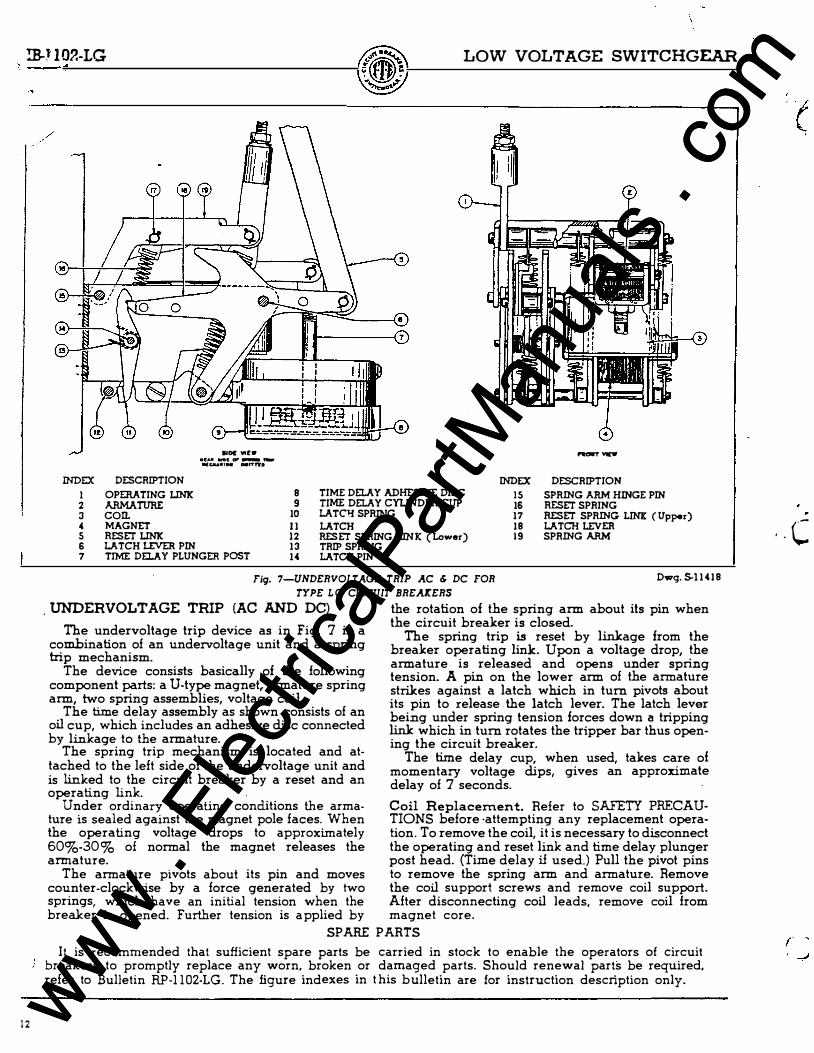
I OPERATING LINK 8 TIME DELAY ADHESIVE DISC IS SPRING ARM HmGE PIN 2 ARMATURE 9 TIME DELAY CYLINDER CUP 16 RESET SPRING 3 con. 10 LATCH SPR!I'!G 17 RESET SPRING LINE: (Upper) " MAGNET 1 1 LATCH 18 LATCH LEVER 5 RESET LINK 12 RESET SPRING LINK ( Lower) 19 SPRING ARM 6 LATCH LEVER PIN 13 TRIP SPRING 7 TIME DEl.A Y PLUNGER POST 14 LATCH PIN
Fig. 7-UNDERVOLT AGE TRIP AC & DC FOR Dwg. S.l 1 4 1 8
TYPE L G CIRCUIT BREAICERS
. UNDERVOLTAGE TRIP (AC AND DC) the rotation of the spring arm about its pin when the circuit breaker is closed.
The undervoltage trip device as in Fig. 7 is a The spring trip is reset by linlcage from the combination of an undervoltage unit and a spring breaker operating link. Upon a voltage drop, the trip mechanism. armature is released and opens under spring
The device consists basically of the following tension. A pin on the lower arm of the armature component parts: a U-type magnet, armature spring strikes against a latch which in turn pivots about arm, two spring assemblies, voltage coil. its pin to release the latch lever. The latch lever
The time delay assembly as shown consists of an being under spring tension forces down a tripping oil cup, which includes an adhesive disc connected linlc which in turn rotates the tripper bar thus open-by linkage to the armature. ing the circuit breaker.
The spring trip mechanism is located and at- The time delay cup, when used, takes care of tached to the left side of the undervoltage unit and momentary voltage dips, gives an approximate is linked to the circuit breaker by a reset and an delay of 7 seconds. operating link.
Under ordinary operating conditions the arma- Coil Replacement. Refer to SAFETY PRECAU-ture is sealed against the magnet pole faces. When TIONS before ·attempting any replacement opera-the operating voltage drops to approximately lion. To remove the coil, it is necessary to disconnect 60%-30% of normal the magnet releases the the operating and reset link and time delay plunger armature. post head. (Time delay if used.) Pull the pivot pins
The armature pivots about its pin and moves to remove the spring arm and armature. Remove counter-clockwise by a force generated by two the coil support screws and remove coil support. springs, which have an initial tension when the After disconnecting coil leads, remove coil from breaker is opened. Further tension is a pplied by magnet core.
SPARE PARTS
It is recommended that sufficient spare parts be carried in stock to enable the operators of circuit breakers to promptly replace any worn, broken or damaged parts. Should renewal parts be required, refer to Bulletin RP-1 102-LG. The figure indexes in t his b ulletin are for instruction description only.
· - C
www . El
ectric
alPar
tMan
uals
. com
www . El
ectric
alPar
tMan
uals
. com

www . El
ectric
alPar
tMan
uals
. com
www . El
ectric
alPar
tMan
uals
. com