. com . ElectricalPartManuals...l I I SVt/ITCHGEAR RENEWAL PARTS ORDERING GUIDE TYPES MA-75C1,...
12
l I I SITCHGEAR RENEWAL PARTS ORDERING GUIDE TYPES MA-75C 1 , MA-250C1 , and MA-350C1 SKY AIR MAGNETIC CIRCUIT BREAKERS WITH 515-1 STORED ENERGY OPERATORS Supplement to 18X5165 18X5166 July, 1974 www . ElectricalPartManuals . com
Transcript of . com . ElectricalPartManuals...l I I SVt/ITCHGEAR RENEWAL PARTS ORDERING GUIDE TYPES MA-75C1,...
l I
I
SVt/ITCHGEAR
RENEWAL PARTS ORDERING GUIDE
TYPES MA-75C1, MA-250C1, and MA-350C1 SKY
AIR MAGNETIC CIRCUIT BREAKERS WITH 515-1 STORED
ENERGY OPERATORS
Supplement to 18X5165 18X5166
July, 1974
www . El
ectric
alPar
tMan
uals
. com
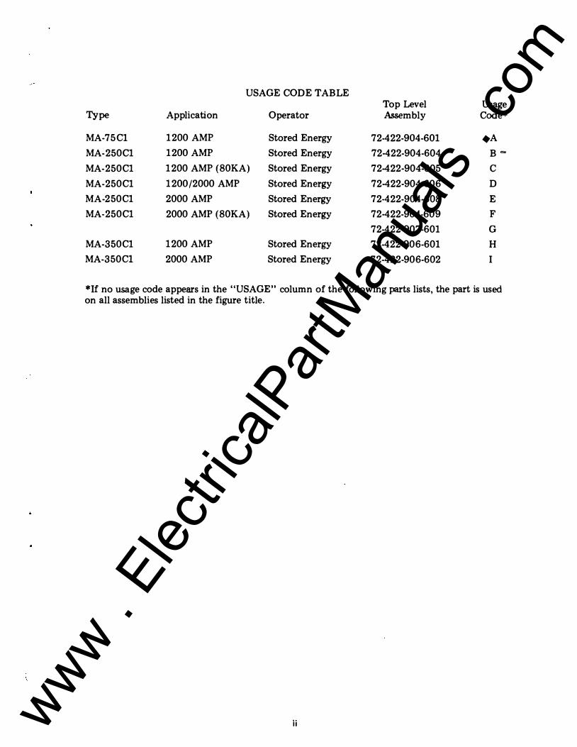
USAGE CODE TABLE Top Level Usage
Type Application Operator Assembly Code*
MA-75C1 1200 AMP Stored Energy 72-422-904-601 A
MA- 250C1 1200 AMP Stored Energy 72-422-904-604 B=-
MA- 250C1 1200 AMP (80KA) Stored Energy 72-422-904-605 c MA- 250C1 1200/2000 AMP Stored Energy 72-422-904-606 D
MA-250C1 2000 AMP Stored Energy 72-422-904-608 E
MA- 250C1 2000 AMP (80KA) Stored Energy 72-422-904-609 F 72-422-907-601 G
MA-350C1 1200 AMP Stored Energy 72-422-906-601 H MA-350Cl 2000 AMP Stored Energy 72-422-906-602 I
*If no usage code appears in the "USAGE" column of the following parts lists, the part is used on all assemblies listed in the figure title.
ii www . El
ectric
alPar
tMan
uals
. com
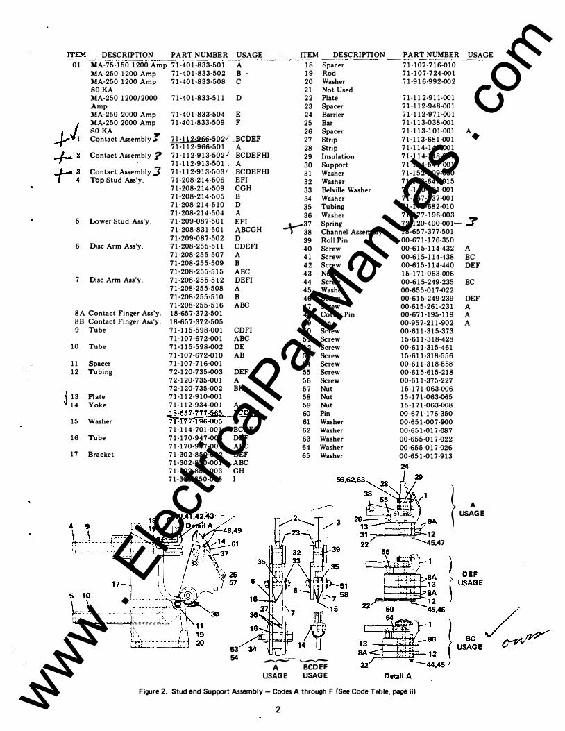
ITEM DESCRIPTION PART NUMBER USAGE
01 )(A-75-150 1200 Amp 71·401-833-501 A MA-250 1200 Amp 71-401-833-502 B -MA-250 1200 Amp 71-401-833-508 C SOKA MA-250 1200/2000 71-401-833-511 D
5
6
7
Amp MA-250 2000 Amp MA-250 2000 Amp 80 KA Contact Assembly T Contact Assembly ? Contact Assembly :J Top Stud Ass'y.
Lower Stud Ass'y.
Disc Arm Ass'y.
Disc Arm Ass'y.
SA Contact Finger Ass'y. 8B Contact Finger Ass'y. 9 Tube
10 Tube
11 Spacer 12 Tubing
I 13 Plate � 14 Yoke
15 Washer
16 Tube
17 Bracket
71·401-833·504 E 71-401-833-509 F
1.!.:!12=Afi6.:5_0.2·' ....BCDEF 71-112-966-501 A 71-112-913-502) BCDEFHI 71-112-913·501 A 71-112·913-503' BCDEFHI 71-208·214-506 EFI 71-208-214·509 CGH 71-208-214·505 B 71·208-214-510 D 71-208-214-504 A 71·209-087-501 EFI 71-208-831·501 .1\BCGH 71·209..()87-502 D 71-208-255-511 CDEFI 71-208-255-507 A 71-208-255-509 B 71-208-255-515 ABC 71-208-255-512 DEFI 71-208-255-508 A 71-208-255·510 B 71-208·255-516 ABC 18-657-372·501 18-657·372-505 71-115-598-001 71-107-672·001 71·115-598-002 71-107-672-010 71-107-716·001 72-120-735-003 72-120-735·001 72-120-735-002 71·112-910-001 71-112-934-001
,J8·657�n:r17-196-005 71-114·701-001 71-170-947·008 71-170-947-007 71-30 2-850·002 71-302-850-001 71-302-850-003 71-302-850-005
CDFI ABC DE AB
DEF A BH
A BCDEF A BCDEF DEF ABC DEF ABC GH I
II • •' --------------- ��==�::::::... .. _-.,'
;._ :!��---------- .--..-
ITEM DESCRIPTION
18 Spacer 19 Rod 20 Washer 21 Not Used 22 Plate 23 Spacer 24 Barrier 25 Bar 26 Spacer 27 Strip 28 Strip 29 Insulation 30 Support 31 Washer 32 Washer 33 Belville Washer 34 Washer 35 Tubing 36 Washer �37 Spring 38 Channel Assembly 39 Roll Pin 40 Screw 41 Screw 42 Screw 43 Nut 44 Screw 45 Washer 46 Screw 47 Screw 48 Cotter Pin 49 Pin 50 Screw 51 Screw 52 Screw 53 Screw 54 Screw 55 Screw 56 Screw 57 Nut 58 Nut 59 Nut 60 Pin 61 Washer 62 Washer 63 Washer 64 Washer 65 Washer
�,....
3
53 54 �-- ......_,_...,
A BCDEF USAGE USAGE
PART NUMBER USAGE
71·107-716..()10 71-107 -724..()01 i 1-916·992..()02
71-11 2-911..()01 71-112-948..()01 71·112-971-()01 71-113-038..()01 71-113-101..()01 A 71-113-681..()01 71-114-147..()01 71-114-148-001 71-114-547..()01 71-152-809..()30 71-158-647..()15 71-140-901..()01 71-167-537..()01 71-172·682..()10 71-177-196..()03 72·120·400..()01- 3' 18-657-377-501 00-671-176-350 00-615-114-432 A 00-615-114-438 BC 00-615-114-440 DEF 15-171-063..()06 00-615-249-235 BC 00-655-017..()22 00-615-249-239 DEF 00-615-261-231 A 00-671-195-119 A 00-957·211-902 A 00-611-315-373 15·611-318-428 00·611-315-461 15·611-318-556 00-611-318-558 00-615·615-218 00-611-375-227 15-171-063..()06 15-171-063-{)65 15-171-063.()()8 00-671-176-350 00-651-007-900 00·651..()17-()87 00-655-017..()22 00-655-017 ..()26 00-651-017-913
24
SA }� .. 12 45.47
Figure 2. Stud and Support Assembly- Codes A through F (See Code Table. page ii)
2 www . El
ectric
alPar
tMan
uals
. com

ITEM DESCRIPTION FOR FIGURE 4.
ITEM DESCRIPTION PART NUMBER USAGE ITEM DESCRIPTIO� PART NUMBER USAGE
Frame & Operator 18-468-553-502 CDEF 46 Nut 00-631-003·204 Assembly 47 Cotter Pin 00-671-195-049
18-468-553-501 ABDE 48 Screw 00·617-499·421
2 Operator Assembly 18-657-514-597 49 Yoke 00·615·114-542
3 Pad 71-116·231·002 HI 50 Yoke 00-691-701-903
4 Washer 71·163-273·002 HI 51 Crank Assembly 18·724-395-501
5 Guide Assembly 71-208-910-501 52 Ball Joint 00-833-573-003
6 Piston Assembly 71-114·161-503 53 Clevis Pin 00·957-211·910
7 Guide Assembly 71-114-765-501 54 Ratchet Plate 00-633-182-060
8 Grounding Contacts 71-114-787 ·502 54A Nut 15·171-063-006
9 Bracket Assembly 71-116-800-501 55 Aux. Switch 71-208-922-505
10 Bracket Assembly 71-116-800-502 56 Channel 72-120-062-001
11 Clamp 15-171-070-002 57 Pin 15-676-386-002
12 Foot Pedal Assembly 72·120-586-501 58 Plate 71-208-856-501
(Includes items 63 & 59 Clamp 00-857-271-105
69) 60 Cement 00-331·121-063
13 Pin 71-104-754-034 61 Clamp 15-171-070-001
14 Rod 72·120·688·001 62 Spring 71-113-502-001
15 Plunger 71·113-442-001 63 Switch 00-871-351-107
16 Yoke End 71-113-487-001 64 Cover 72-120·228·001 17 Rod End 71-113·541-001 65 Shim 71-108-654-006 18 Spring 71-113·621·001 66 Screw 00-615-114-384 19 Cup 71-114-151-002 67 Washer 71·15 2·809-012 20 Compression Spring 71-114·153-001 68 Nut 15-171-063-004 21 Bumper 71-114·154-001 69 Bracket 72-220-07 3-001 22 Cylinder 71·114·155·003 70 Crank Assembly 18-724-395-501 23 Packing 71-114·156-001 71 Nut 00-631-003-204 24 Spring 71-114-733-001 72 Nut 00·633·025·216 25 Stop 71-114-749-002 73 Spring 71-204-604·028 26 Link 71-114·752·001 74 Pull Rod 18-657-522-262 27 Tube 71-114-860·002 75 Nut 00-855-759-104 28 Bracket 71·114-786-001 76 Flex Shaft Support 18-652-523-335
29 Block Assembly 18·657-410·599 77 Sec. Disconnect Ass'y. 72-120-287-501
30 Valve Disc 71·115·244-001 78 Washer 71-152-908-002
31 Guard 71·118·452·001 79 Roll Pin 00-671-176-189
32 Compression Spring 71-140·125-001 80 Roller 72·120-706-001
33 Pin 71·915·161-032 81 Bolt 00-611·343-030
34 Pin 71-919-736·009 82 Nut 00-633-025-220
35 Rivet 00·671-501-030 83 Bracket 18-723-506-001
36 Indicator 72-120·190-001 84 crank Assembly 18-723-507-501
37 Bracket 18-657-491·589 85 Pin 00-957-211-901
38 Roll Pin 00-671-176-377 86 Pin 00-671-195-119
39 Rod 72·120·594·001 87 Yoke End Adj. 00·691·701·901
40 Wheel 15-171-067-002 88 Nut 00-631-003-204
41 Eye End 00·691-713·102 89 Pin 00·957·221-010
42 Bar 72·120·689-001 90 Pin 00-671·195-119
43 Washer 71-152·809-002 91 Link 18·657-767-327
44 Pin 72·120-578-001 92 Pin 15-171-181-002
45 Lever Assembly 72·120-568-500
i I "-··
4 www . El
ectric
alPar
tMan
uals
. com

ITEM DESCRIPTION FOR FIGURE 5. ITEM DESCRIPTION PART NUMBER USAGE ITEM DESCRIPTION PART NUMBER USAGE
1 Frame Assembly 18·469-1 02-501 69 Scr�w 00-615-245-222 2 Needle Bearing 00-813-119-810 70 Lock washer 00-655-017-022 3 Needle Bearing 00-813-119-814 71 Screw 00-615-245-218 4 Needle Bearing 00-813-119-821 72 Term. Block Supp. 18-657-524-11.1 5 Pawl Assembly 18-657-485-536 Bracket 6 Stop Bracket Ass'y. 18-657-513-576 73 Term. Block 00-857-036-012 7 Shaft 18-657-467-291 74 Screw 00-615-471-124 8 Slit Spacer 18-657-800-113 75 Lockwasher 00-655-04 7-060 9 Collar 18-657-467-290 80 Chain Link 00-831-349-065
10 Inner Race** 18-657-467-335 81 Pin 18-657-464-105 11 Spacer 18-158-935-009 82 Retaining Ring 00-673-165-075 12 Thrust Washer 00-815-225-131 83 Washer 71-152-809-026 13 Needle Bearing 15-813-119-003 84 Radius Arm 18-390-227-501 14 Pin 18-657-463-368 85 Stop 18-657-464-118 15 Stop Latch 18-657-463-388 86 Washer 00-655-067-200 16 Trip Latch 18-657-463-390 87 Check Switch Brkt. 18-657-782-273 17 Pin 18-657-464-012 88 Grease 00-337-131-001 18 Pin 18-657-523-064 89 Grommet 00-691-872-130 19 Shaft 18-657-463-389 90 Spring Retainer 18-657-523-038 20 Motor* 18-469-223 91 Shaft 18-65 7-463-369 21 Charge Disc. Actuator 18-65 7-522-305 92 Drive Block 18-657-465-170 22 Bracket 18-657-522-304 93 Bearing Block 18-657-463-370 23 . Interlock Rod 18-657-522-269 94 Spring 15-171-331-001 24 Roller Bearing 15-813-073-003 95 Spring 15-171-331-003 25 Torsion Spring 18-657-466-081 96 Retaining Ring 00-673-165-100 26 Torsion Spring 18-657-466-080 97 Retaining Ring 00-673-165-087 27 Pawl Return Spring 18-65 7-229-240 98 Shim 18-657-784-007
_....if Conical Spring 18-657-522-242 99 Screw 00-615-114-556 Retaining Ring 00-673-165-062 100 Flex. Shaft Assembly 18-657-768-377
30 Spacer 18-158-935-011 101 Roll Pin 00-671-176-185 31 Adj. Screw 00-617-499-37 5 102 Clamp 15-171-386-002 32 Roll Pin 00-671-176-224 103 Washer 71-114-297-001 33 Roll Pin 00-671-176-325 104 Link 71-118-760-001 34 Roll Pin 00-671-176-383 105 Link 18-657-464-103 35 Roll Pin 15-671-173-002 106 Roller 15-813-073-001 36 Roll Pin 00-671-171-375 107 Pin 18-657-464-104 37 Washer 18-657-522-303 108 Spring 18-657-523-331 38 Washer 71-152-809-024 109 Washer 71-152-809-026 39 Screw 00-615-245-218 110 Spring Holder 18-657-523-332 40 Lockwasher 00-655-017-022 111 Retaining Ring 00-67 3-}.65-075 41 Screw 00-611-315-392 112 Spring Anchor 18-657-523-333 42 Washer 00-651-007-160 113 Link 18-657-800-115 43 Lockwasher 00-655-017-026 114 Needle Bearing 00-813-119-813 44 Elastic Stop Nut 00-633-025-116 115 Plate 18-723-641-001 45 Jam Nut 00-631-143-104 116 Terminal Block 00-857-036-012 46 Roll Pin 00-671-176-373 117 Microswitch* 15-171-323-001 47 Roll Pin 00-671-171-379 118 Microswi tch * 15-171-323-002 48 Spacer 18-657-523-278 119 Actuator Arm 18-657 ·522-355 49 Flex Shaft Support 18-657-523-335 120 Shield 18-657-468·090 50 Roll Pin 00-671-176-189 121 Extension Spring 18-657-523-061 51 Ratchet Assembly 18-390·202-501 122 Screw 00-615-471-130 52 Cam Assembly } 18-389-061-501 123 Washer 00-655-047-060 53 Cam Assembly ***
18-389-061-502 124 Nut 14-147-052-002 54 Linkage Assembly 125 Screw 00-617-247-468
(Consists of items 126 Nut 00-631-171-106 104 to 113) 127 Washer 00-655-017-032
55 Motor & Closing 18-390-246-501 128 Washer 00-651-007-230 Control 129 Screw 00-615-471-124
56 Indicator Assembly 18-723-511-501 130 Screw 00-615-485-216 57 Bracket Assembly 18-657-491-589 131 Washer 00-655-017-022 58 Pin 18-724-690-003 132 Washer 00-651-007-907 59 133 Relay 00-871-797-107 60 Solenoid Trip Link 18-657-770-518 00-871-797-108
Assembly 00-871-797-109 61 Switch Bracket 15-171-367-001 00-871-797-115 62 Roll Pin 00-671-176-309 134 Washer 00-655-04 7-080 63 Solenoid* 1'5-171-339 .135 Screw 00-615-223-17 4 64 Solenoid* 15-171-339 136 Relay 25-134-022-501 65 Trip Latch Switch* 15-171-323- 25-134-022-502 66 Strip 18-657-467-239 *Give breaker SIN and control voltage 67 Screw 00-615-223-172 when ordering item. 68 Lockwasher 00-655-017-020 **Must be supplied in pail'll.
***Must be supplied as matched set.
6 www . El
ectric
alPar
tMan
uals
. com

81,82,83
I SIDE VIEW 86
VIEWS
90
VIEWC
8
108 104
82 81-----...i
110-109 111
FRONT VIEW
•
www . El
ectric
alPar
tMan
uals
. com
. J
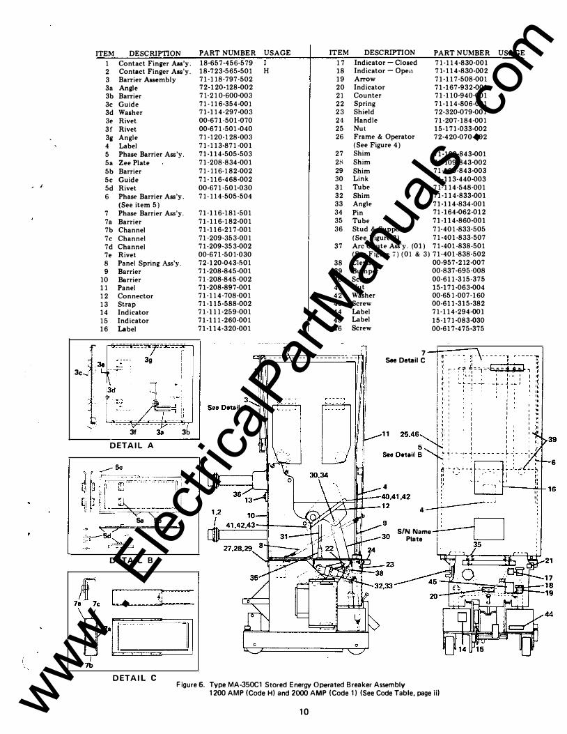
ITEM DESCRIPTION
1 Contact Finger Ass'y. 2 Contact Finger A.ss'y. 3 Barrier Assembly 3a Angle 3b Barrier 3c Guide 3d Washer 3e Rivet 3f Rivet 3g Angle 4 Label 5 Phase Barrier Ass'y. 5a Zee Plate 5b Barrier 5c Guide 5d Rivet 6 Phase Barrier Ass'y.
(See item 5) 7 Phase Barrier Ass'y. 7a Barrier 7b Channel 7c Channel 7d Channel 7e Rivet 8 Panel Spring Ass'y. 9 Barrier
10 Barrier 11 Panel 1 2 Connector 1 3 Strap 14 Indicator 1 5 Indicator 16 Label
------------ ------f - --- ----
�'� . 3g
3c -�
i n +
..._ _ _ __
': ' 3f 3a DETAIL A
u ff �5-� ........ � ·-----, �: llr_Ll �:·n·,· --n:;=�.-o.c- ---or.·l. ,!. I I :: li i ' I>J r, I 'I : 'I'Jt::,� Jl I IV .: U��� . '
' 0 =� -- """'- _____ :__] 5a 5b
DETAIL B
DETAIL C
3b
PART NUMBER USAGE ITEM
18-657-456-579 I 1 7 18-723·565-501 H 18 71-11 8-797-502 19 72-120-128-002 20 71-21 0·600-003 21 71 -11 6-354-001 22 71-11 4-297-003 23 00-671-501-070 24 00-671 -501 -040 25 71 -1 20-1 28-003 26 71-1 13-871 -001 71-114-505-503 27 71-208-834-001 28 71 -11 6-1 82-002 29 71 -11 6-468-002 30 00-671 -501-030 31 71-11 4-505-504 32
33 71-11 6-1 81 -501 34 71-1 1 6-1 82-001 35 71-1 16-217-001 36 71 -209-353-001 71 -209-35 3-002 37 00-671-501-030 72-120·043-501 38 71 -208-845-001 39 71 -208·845-002 40 71·208-897-001 41 71-1 1 4-708-001 42 71 ·115-588-002 43 71 -111-259·001 44 71-111 -260-001 45 71-114-320·001 46
37
DESCRIPTION PART NUMBER USAGE Indicator- Closed Indicator- Open Arrow Indicator Counter Spring Shield Handle Nut Frame & Operator (See Figure 4)
71 -1 1 4-830·001 71·1 14·830-002 71-117-508-001 71-167-932-001 71-110-940·001 71 -114-806-001 72-320-079-001 71-207-184-001 15-171-033-002 72-420-070-502
Shim 71-109-843-001 Shim 71·109-843·002 Shim 71 -109-843-003 Link 71-113-440-003 Tube 71-11 4-548-001 Shim 71-114-833-001 Angle 71-114-834-001 Pin 71 -164-062-012 Tube 71-114-860-001 Stud & Support 71-401 -833-505 (See Figure 2) 71 -401-833·507 Arc Chute Ass'y. (01) 71 -401 -838-501 (See Figure i) (01 & 3) 71 -401-838-502 Clevis 00-95 7 ·212-007 Bumper 00-837-695-008 Screw 00·611·315-375 Nut 15·171-063·004 Washer 00-651 .007-160 Screw 00-611-315-382 Label 71 ·114-294.001 Label 15-171-083.030 Screw 00-617-475-375
7 See Detail C
I 11 v
6
r----"'--1-16 ....._,_____, ::: .,,
0
S/N Name Plate
17 11;211�-18
1-WCJ_,..._,g
44
Figure 6. Type MA-350C1 Stored Energy Operated Breaker Assembly 1200 AMP (Code Hl and 2000 AMP (Code 1 l (See Code Table, page iil
10 www . El
ectric
alPar
tMan
uals
. com
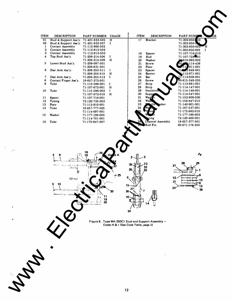
ITEM DESCRIPTION 01 Stud & Support Ass'y. 02 Stud & Support Ass'y.
1 Contact Assembly 2 Contact Assembly 3 Contact Assembly 4 Top Stud Ass'y.
5 Lower Stud Ass'y.
6 Disc Arm Ass 'y.
7 Disc Arm Ass 'y. 8 Contact Finger Ass'y. 9 Tube
10 TubE'
11 Spacer 12 Tubing 13 Plate 14 Yoke
15 Washer
16 Tube
·, -
PART NUMBER USAGE ITEM DESCRIPTION
71-401-833-505 H 1i Bracket 71-401-833-507 I 71-112-966-502 71-112-913-502 71-112-913-503 18 Spacer 71-208-214-506 I 19 Rod 71-208-214-509 H 20 Washer 71-209-087-501 21 Screw 71-208-831-501 22 Plate 71-208-255-511 I 23 Spacer 71-208-255-515 H 24 Barrier 71-208-255-512 I 25 Bar 18-657-372-501 26 Screw 71-115-598-001 I 27 Strip 71-107-672-001 H 28 Strip 71-115-598-002 I 29 Insulation 71-107-672-010 H 30 Support 71-107-716-001 31 Washer 72-120-735-003 32 Washer 71-112-910-001 33 BE'Iville Washer 18-657-777-565 34 Washer 71-114-697-001 35 Tubing 71-177-196-005 36 Washer 71-114-701-001 37 Spring 71-170-94 7-007 38 Channel Assembly
39 Roll Pin
34
Figure 8. Type MA-350C1 Stud and Support AssemblyCodes H & I (See Code Table, page ii)
12
PART NUMBER
71-302-850-002 71-302-850-001 71-302-850-003 71-302-850-005 71-107-716-010 71-107-724-001 71-916-992-002 00-615-114-438 71-112-911-001 71-112-948-001 71-112-971-001 71-113-038-001 00-615-249-235 71-113-681-001 71-114-147-001 71-114-148-001 71-114-547-001 71-152-809-030 71-158-647-015 71-140-901-001 71-167-537-001 71-172-682-010 71-177-196-003 72-120-400-001 18-657-377-501 00-671-176-350
28 29 21 �
c�mf�' 13 . . : :' .� 8 _. _ .. ,. 13 31 l -� ;;:r : ·:: ; �
USAGE
H I
www . El
ectric
alPar
tMan
uals
. com

.,..,."' t 3
� � 7 8 9 10 1.1. IZ 1'3 l"t
IZ 17 I
'
CORRECTION SHEET
ATTACH TO:l8X5166 Page 1 or 2
This sheet(s) notes changes which should
be made in the attached instruction booklet:
OI!SC.�IPTIO,_. P!i"'S� e,... ..... � - C:T .. PMA.SS" '&...,tt.._, .... • L �
..J'JtA')C: &"'W.Il.IQf., -st"' F•o......,. a�···�C.. � . ...... e .. ll__ .. •aa..- �c:���...
}te.���o.. I!."·· •c. a. - �..��� ..... Sc:•L- (P'�"'-.:.�·2) NvT Su�P6&.T Sw�fi'ULT' �t: ....... �..,,. s(.. z5 .. 3 "'7S 1-4 'S-ro..,�a. locWilwu-r-. 2, �o"""l>"""'s;,..\.tlt. ---.RJ �-�� .. "'• eAr sn�- .J, .... �L.'i a • .,N • ..,.-s-....;;.&. -·'31 L..(..C."WO-.s;�i,.L -·!oj ... IIi. ""'"
PII\I!.T ""'a"e�� '71-2D8-0'3�-5o I "'71-11 "+-,.0!5 -S'o 1 "71-1 1'+-5oS. Soz.. 71-ZOB-8'+5'· 001 71- zos-a .. s. ooz. (1·1 16 • 7!i!i""1- 5"0 I 00-,1"7-'+75-'3.,5" IS-171· 03'3- ooz.
7Z.· IZO • :20 3 ·00 I 71·ZIO· "0 I· 002. Oo·" II -�15 ·"397 15"-171-0b3-0o'fOo-"SI· 007- l'+(o 00-" II - "315"• 'tl7 OO- bSI· oo;- .9oo 00-655-0 •7- 030 00-G.ol t -�,�- L.f.l9
• I • I • 5
�"" I
z '3 'f !5 " 7 8 �
10 II 12. I� , ...
I :b<:s<�·��·•oJ
�W"SL�·I..·Ioi.-c-rk- .. ·"'
�llt.o .. ""' &At�.a.IE.Il R a."a.. e. ...... ._,�._
"5u•Po-.."T loll:• '-"D c.-.. Sf .. . . 2� -.3.'75 \..(� S"Tovc.-. l....oc: ""'"'\I"T- -2S llteuwo-"S\.4IE.._ --"2.'$
l-4t:a. HI!> C."P'S(". -.31• -•'Z. ....... R.e�o� ... O.....-.�\oofl£._-. ""!.1 LOcoc....., .. ,...,. .. .._ -.31
lll-7ZJ- Sll .. - SOL 18-'7'2�· 58"t- So'3
7\·Z:D \. '-'01-DO'Z,. "" ·"' , ...... ,,s.,,'7 1 S- ,.., 1- oc. 'S ... flo'+ oo-651-oo�. ,..,. oc • • , I -11otS- "fot7 DtJ • "S I • 0 0 7 • !!)GO 00-45S -0\7- 03o
IS" I. 17 IS k&"ll. WD CIIIP S(& . • 'JI•1 .. w _:;·"7�S'"��fo�___l!_l !S�-��.!1!.1 ;_· .!!'S.! I.!6:_:-:.;:! .. :!.0:J;;:..o
OLD b&.�IG.to.J ---' ... �--�'J:)aStC.al ---:.... P'-.loA. Tu F &.a •• t37.S"" £F'F" t:"&:&.,t!>?S
These instructions do not purport to cover all details or variations in equipment nor to provide far e very possible contingency to be met in connection with installation, operation or maintenance.
A ----
I,,: :;';�:LV\0.i����; S\NITCHGEAR -;,'
DIVISION www . El
ectric
alPar
tMan
uals
. com

"
�"'
� 3
1-" 7 8 9 LO 1.1.
12 I'll l't
�� 17 I
CORRECTION SHEET
ATTACH T0:18X5166 Page 1 or 2
This sheet(s) notes changes which should
be made in the attached instruction booklet:
OeSc.R.IPTION P�-.'55. &tl. .. ILJIL- ,,.. .. PHIII.SS" 'eollltt.-., .... - L �
...f'M.A�C. &,_,._.._,£A.- R \.4. F,.o...,"T &!""•••�«... lit• ... ._ e .......... ..__ �c ... ft�l'l,._ a ....... ;. HE.k - UP� ..... ScaEw c� ...... ��·c.� ,...,.,. SuPf'o&.T �\>PPoa,T Ht:-. 1-4D' C."-1" S(-. -2!i• 3'?S 1..4 'STo .... •c. loc�o<" ... uT"--2, r:r.., ....... p .... ... s.o.l�· -·'2J 1-j!OI< 1-4. CAf" 5nl. .J!•.I.'Z.\..f, IC: ....... lh••""SH�& -.')j l.,..(o(¥f"S""i.L -·31 1-tE• HJo H 'c �o�
PI'IRT NUMel::� 7t-2o8-��3-So 1 r 1- t I "+- !!!J"O !i- So \ "71-1 1"+-5oS- So:z... 71-ZOB-8'+-5- 001 71- ZoS-8"+5- 002. 71-116·79'7- So I OO-Eo1"7-'t75-"37!) 15-171- 03"3- ooz. 7Z.-IZO- 20 3-001 7 1-ZIO- 1&0 1- ooz 00-" I I -"315 -397 15"-171- 01&3-oo'f 00-bSI- 007- 1'+<o 00-1& II - "3 IS"- '-117 oo. bSI- oo7- .9oo 00-655-017-030 Oo--tt -�tS'•Lf.J9
- I - I - .9
OLD �IL'S.tG."'-1 ...... 0 .. � �� ... � 1�7.5'
ITE.N\ I
z " '+ .5 ... 7 8 :>
IC II 12. 13 , ... IS" I" ,., 18
I = .. ,., .... � .. ...,
t"'�-.<! L� - �-�.-c ... -.- ... �
��a ....... &A•tllt.•�lll. R��:."ft.. � .... ... .,,..:,...._
"-su!O'Poa.,. �E• 1-1.0 c"'r StC . 2'5 ,..3.1' 1-£ .. STov&-. Loc: .,...,....,.. - ·25" R: • ., ... D_...,s'"'c-.. -- '3-!S \oole.:w. HJ) C"�S(C -,3 I ... f.2 I-" Ro.,..,.O_'!o.._.£.._ - . "3\ LOC>C:""'-1"''- ... C ... -·31
I' PJ'IIk ... Nv..,.�,_._ 7t-tt8- o�t-q_o3
18- 7Z3- Se't- SOL t8-'7'2�- S&"t- So'3
7\-Z.0\-"01-00� �D ·"II� ... I.S·3�"'f I$"- I i I - 0'-' 3 • Do '+ oo-•SI-o07. l"+f. 00- "'I I ---IS- "tf7 Do • '"s t - o o.,. • ,!!too I 00- t.ss -o\7- 03o
H &"• MD c•P s �-.. · "1•-�-c<·"7�Sc_!�::_<4�_!LI 5�-��.!.1 !_:I ·:_ll�l �&�-:_'+=1 ��
These instructions do not purport to cover all details or variations in equipment nor to provide for e very possible contingency to be met in connection with installation, operation or maintenance.
A .-....ow..._
S\NITCHGEAR DIVISION www .
Elec
tricalP
artM
anua
ls . c
om

!
ATTACH TO: 18X5166 Page 2 or 2
ITEM
CORRECTION SHEET This sheet(s) notes changes which should
be made in the attached instruction booklet:
%:)&$( ... 1ti"TIO...,
WA•• a��toa • ._IIL..-C ..... �""'· ••••• & ... - ....... f"tj'f',.. � .......... -"-... ""�·-� ... ""' .. ... ....... ..... , .... -� ....... ....... . AIULI&IL - ..,_.,.. .. -..
-IJyc...c
_ SeC.�- cA• •c•- -�1 w I·I.S_-.., �-·.!'••1"_ ... __ ,., L..•c;ll[w••..,c• -ea1 ..... .:. M.a .. C' ........ -. S••·C.& ... H•ll. ...,._ �•I' $1"&-··1 •• '71" .....
I•U'--IJ!;I- •1 il:t::t:J:J:l�� "''·••e-I¥S·oe_·,--.., ... ...... . ...... ..... -"71-11··�-'7·5•'1.'71 ·IIS·Sia-•'i.. '71-fiG.-IIa-oot 00·6.1S• IZ"f· I+Z.'+ IO .. "J'I· Oo'T-aeo #o ... ftSS'-et1. ••o Oe-. '··�··- .. , ..., ··- ... ....... .... �
IT�N I L
_) ' • 7 8 • 10 " . .. ·�
� .. ,. ······� .." .. ....... .......
-.:.,.. .... ,.. ... er.oc.te. 5-.·"4•· '"'" sc._ ... �111• \.'Z.�&..i' fit•--.,. ....... - .. ,, Lac.ll(wlllto•wlll._- -�1 H&•- w.» c;t,. sc&···'ll ..c. ·'-'1""
, ... .,.a .. -s••- .... ••-�z•-•••·HI"
7•- t•s- •••-o•L 71-116.- 18a-DOI tto-•••· 12.."+ �'+2. '+ "o-6.s•-••"7· �oo DD· WSS-Of7· o� o
• t.l '-'StS'- 'II?
These instructions do not purport to cover all detai ls or variations i n equipment nor to provide for every possible contingency to be me t in connection wi th installation, operation or maintenance.
----------�----------------�--------------------�-------
A .... ,.._
1<
,,, ': •. :, ·"t; .;:;(•,�:. < ' ,:._\�1/�.;��f;:,,:.':;,�� · �··aWITCHGE�'"I::f?�"�·J< •
DIVIBII:JN
www . El
ectric
alPar
tMan
uals
. com

www . El
ectric
alPar
tMan
uals
. com