
* 321 6HULHV - eoptolink.com · *esv qp &rqwlqxrxv 0rgh 7udqvplwwhu zlwk (0/ odvhu ... ,qwhuqdo , &...
10
10G PON Series Preliminary Eoptolink Technology Inc., Ltd. Page 1 of 10 EOLX-PX-GT-30 Compliant with ITU-T G.987.2 N1 Class Single fiber bi-directional Transceiver 2.488Gbps upstream and 9.953Gbps downstream RoHS6 Compliant Ordering information Part No. Input Output Fiber Interface Temperature EOLX-PX-GT-30-D AC DC SMF SC Standard EOLX-PX-GT-30-DI AC DC SMF SC Industrial *The Product image only for reference purpose Features XFP MSA package with SC receptacle optical interface 9.953 Gbps/1577 nm Continuous Mode Transmitter with EML laser 2.488Gbp/1270nm High Sensitivity Burst-Mode APD-TIA Receiver Supports Digital Diagnostic Monitoring Functions Burst mode received signal strength indication (RSSI) output LVCML interface logic level for 2.488Gbps data output LVCML interface logic level for 9.953Gbps data input Operating Case Temperature Standard:0℃~+70℃ Industrial: -40℃~+85℃ Compliant with Class 1 FDA and IEC60825-1 laser safety Applications XG-PON N1 Class
Transcript of * 321 6HULHV - eoptolink.com · *esv qp &rqwlqxrxv 0rgh 7udqvplwwhu zlwk (0/ odvhu ... ,qwhuqdo , &...

10G PON Series Preliminary
Eoptolink Technology Inc., Ltd. Page 1 of 10
EOLX-PX-GT-30 Compliant with ITU-T G.987.2 N1 Class
Single fiber bi-directional Transceiver
2.488Gbps upstream and 9.953Gbps downstream
RoHS6 Compliant
Ordering information
Part No. Input Output Fiber Interface Temperature
EOLX-PX-GT-30-D AC DC SMF SC Standard
EOLX-PX-GT-30-DI AC DC SMF SC Industrial
*The Product image only for reference purpose
Features
XFP MSA package with SC receptacle
optical interface
9.953 Gbps/1577 nm Continuous Mode
Transmitter with EML laser
2.488Gbp/1270nm High Sensitivity
Burst-Mode APD-TIA Receiver
Supports Digital Diagnostic Monitoring
Functions
Burst mode received signal strength
indication (RSSI) output
LVCML interface logic level for
2.488Gbps data output
LVCML interface logic level for
9.953Gbps data input
Operating Case Temperature
Standard:0℃~+70℃
Industrial: -40℃~+85℃
Compliant with Class 1 FDA and
IEC60825-1 laser safety
Applications
XG-PON N1 Class

10G PON Series Preliminary
Eoptolink Technology Inc., Ltd. Page 2 of 10
Regulatory Compliance*
Product Certificate Certificate Number Applicable Standard
TUV R50135086
EN 60950-1:2006+A11+A1+A12+A2
EN 60825-1:2014
EN 60825-2:2004+A1+A2
UL E317337 UL 60950-1
CSA C22.2 No. 60950-1-07
EMC CE AE 50285865 0001 EN 55022:2010
EN 55024:2010
FCC WTF14F0514417E 47 CFR PART 15 OCT., 2013
FDA / CDRH 1040.10
ROHS / 2011/65/EU *The above certificate number updated to June 2014, because some certificate will be updated every year, such as
FDA and ROHS. For the latest certification information, please check with Eoptolink.
Product Description
EOLX-PX-GT-30 Series is a transceiver for the optical line terminal (OLT) of XGPON with
9.953Gbps in downstream and 2.488Gbps in upstream. EOLX-PX-GT-30 series is high
performance module for single fiber communications by using 1577 continuous-mode transmitter
and 1270nm burst-mode receiver.
The transmitter section uses an EML 1577nm laser and is a class 1 laser compliant according to
International Safety Standard IEC-60825-1. The receiver section uses an integrated 1270 nm
detector preamplifier (IDP) mounted in an optical header and a limiting post-amplifier IC.
Absolute Maximum Ratings
Parameter Symbol Min. Max. Unit Storage Temperature TS -40 +85 °C
Operating Relative Humidity Hopr 5 85 %
Power Supply Voltage Vcc3 0 3.6
V Vcc5 0 5.5
Damage Threshold Receiver PIN-Damage 5 dBm
ESD Voltage 1000 V
*Exceeding any one of these values may destroy the device permanently.
10G PON Series Preliminary
Eoptolink Technology Inc., Ltd. Page 3 of 10
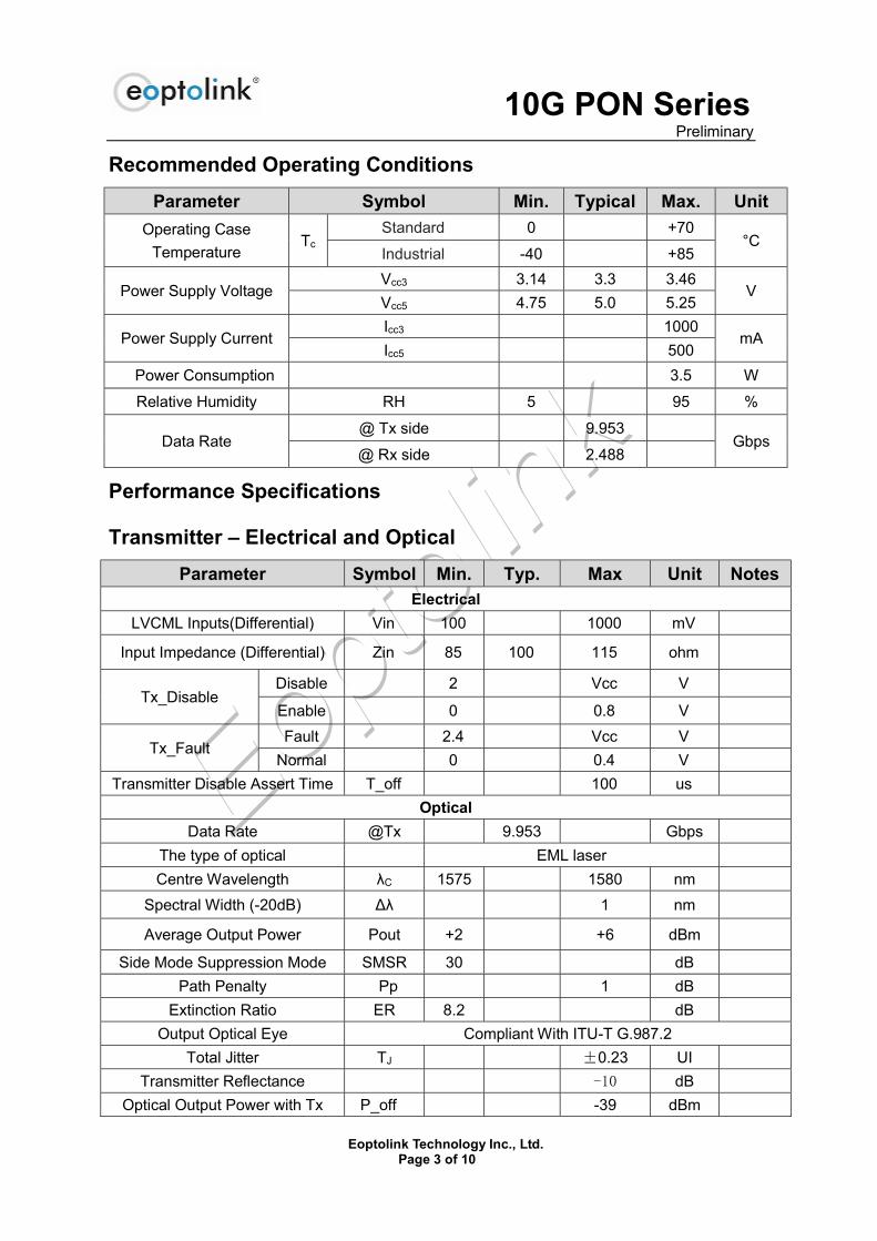
Recommended Operating Conditions
Parameter Symbol Min. Typical Max. Unit
Operating Case
Temperature Tc
Standard 0 +70 °C
Industrial -40 +85
Power Supply Voltage Vcc3 3.14 3.3 3.46
V Vcc5 4.75 5.0 5.25
Power Supply Current Icc3 1000
mA Icc5 500
Power Consumption 3.5 W
Relative Humidity RH 5 95 %
Data Rate @ Tx side 9.953
Gbps @ Rx side 2.488
Performance Specifications
Transmitter – Electrical and Optical
Parameter Symbol Min. Typ. Max Unit Notes Electrical
LVCML Inputs(Differential) Vin 100 1000 mV
Input Impedance (Differential) Zin 85 100 115 ohm
Tx_Disable Disable 2 Vcc V
Enable 0 0.8 V
Tx_Fault Fault 2.4 Vcc V
Normal 0 0.4 V
Transmitter Disable Assert Time T_off 100 us
Optical
Data Rate @Tx 9.953 Gbps
The type of optical EML laser
Centre Wavelength λC 1575 1580 nm
Spectral Width (-20dB) Δλ 1 nm
Average Output Power Pout +2 +6 dBm
Side Mode Suppression Mode SMSR 30 dB
Path Penalty Pp 1 dB
Extinction Ratio ER 8.2 dB
Output Optical Eye Compliant With ITU-T G.987.2
Total Jitter TJ ±0.23 UI
Transmitter Reflectance -10 dB
Optical Output Power with Tx P_off -39 dBm
10G PON Series Preliminary
Eoptolink Technology Inc., Ltd. Page 4 of 10
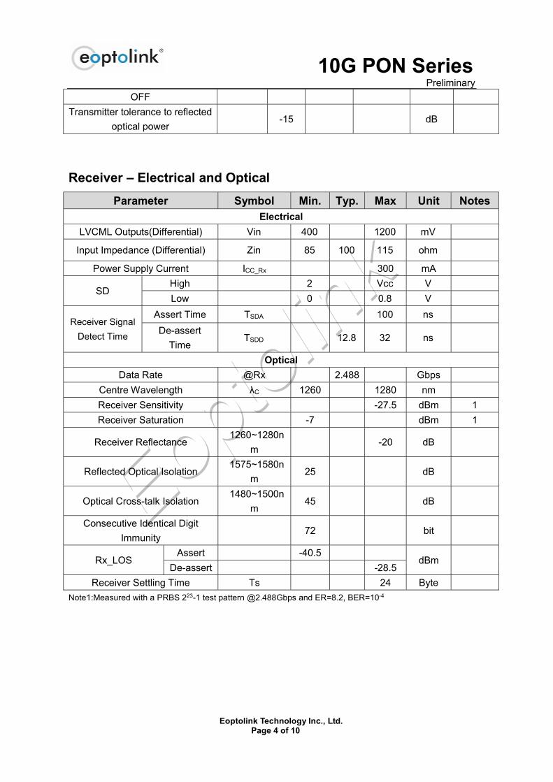
OFF
Transmitter tolerance to reflected
optical power -15 dB
Receiver – Electrical and Optical
Parameter Symbol Min. Typ. Max Unit Notes Electrical
LVCML Outputs(Differential) Vin 400 1200 mV
Input Impedance (Differential) Zin 85 100 115 ohm
Power Supply Current ICC_Rx 300 mA
SD High 2 Vcc V
Low 0 0.8 V
Receiver Signal
Detect Time
Assert Time TSDA 100 ns
De-assert
Time TSDD 12.8 32 ns
Optical
Data Rate @Rx 2.488 Gbps
Centre Wavelength λC 1260 1280 nm
Receiver Sensitivity -27.5 dBm 1
Receiver Saturation -7 dBm 1
Receiver Reflectance 1260~1280n
m -20 dB
Reflected Optical Isolation 1575~1580n
m 25 dB
Optical Cross-talk Isolation 1480~1500n
m 45 dB
Consecutive Identical Digit
Immunity 72 bit
Rx_LOS Assert -40.5
dBm De-assert -28.5
Receiver Settling Time Ts 24 Byte
Note1:Measured with a PRBS 223-1 test pattern @2.488Gbps and ER=8.2, BER=10-4
10G PON Series Preliminary
Eoptolink Technology Inc., Ltd. Page 5 of 10
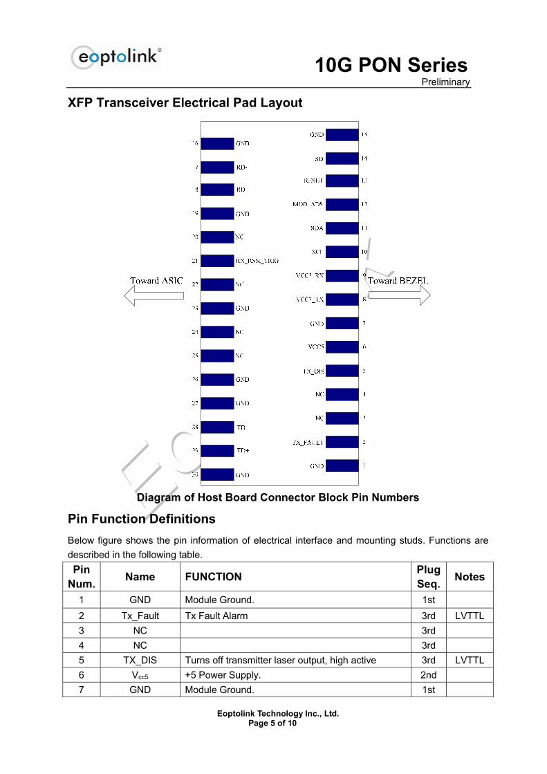
XFP Transceiver Electrical Pad Layout
Diagram of Host Board Connector Block Pin Numbers
Pin Function Definitions
Below figure shows the pin information of electrical interface and mounting studs. Functions are
described in the following table.
Pin Num.
Name FUNCTION Plug Seq.
Notes
1 GND Module Ground. 1st
2 Tx_Fault Tx Fault Alarm 3rd LVTTL
3 NC 3rd
4 NC 3rd
5 TX_DIS Turns off transmitter laser output, high active 3rd LVTTL
6 Vcc5 +5 Power Supply. 2nd
7 GND Module Ground. 1st

10G PON Series Preliminary
Eoptolink Technology Inc., Ltd. Page 6 of 10
8 Vcc3 +3.3V Power Supply 2nd
9 Vcc3 +3.3V Power Supply 2nd
10 SCL Serial 2-wire interface clock. 3rd LVTTL
11 SDA Serial 2-wire interface data line. 3rd LVTTL
12 MOD_ABS Module Absent; Indicates module is not present.
Grounded in the module. 3rd LVTTL
13 RX_RESET Burst Module Reset Signal, assert high at the end of
previous burst, typically 4 bytes in duration 3rd LVTTL
14 SD Receiver Signal Detect Indicator. 3rd LVTTL
15 GND Module Ground. 1st
16 GND Module Ground. 1st
17 RD- Receiver Inverted Data Output 3rd LVCML
18 RD+ Receiver Non-Inverted Data Output 3rd
19 GND Module Ground. 1st
20 NC 3rd
21 RX_RSSI_TRIG High value indicated ready for RSSI measurement 3rd LVTTL
22 NC 3rd
23 GND Module Ground. 3rd LVTTL
24 NC 3rd
25 NC 3rd
26 GND Module Ground. 3rd
27 GND Module Ground. 1st
28 TD- Transmitter Inverted Data Input 3rd LVCML
29 TD+ Transmitter Non-Inverted Data input 3rd LVCML
30 GND Module Ground. 1st
Digital RSSI Timing Characteristics
10G PON Series Preliminary
Eoptolink Technology Inc., Ltd. Page 7 of 10
Digital RSSI Timing Specification
Parameter Symbol Min. Typ. Max Unit Notes Optical Input Signal Duration Time Tont 300 ns
RSSI trigger delay Ttri 0 3000 ns
RSSI Trigger Width Tw 300 Tont-Ttri ns
Internal I2C Delay Tp 500 us
Digital Diagnostic Functions
Eoptolink’s EOLX-PX-GT-30 Small Form Factor 10Gbps (XFP) transceivers are compliant with the
current XFP Multi-Source Agreement (MSA) Specification Rev 4.5.
As defined by the XFP MSA, Eoptolink XFP transceivers provide digital diagnostic functions via a
2-wire serial interface, which allows real-time access to the following operating parameters:
Transceiver temperature
Laser bias current
Transmitted optical power
Received optical power
Transceiver supply voltage
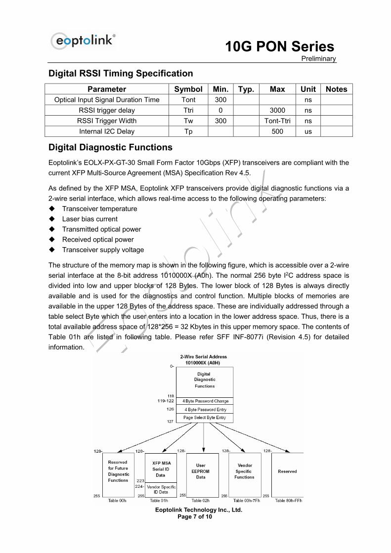
The structure of the memory map is shown in the following figure, which is accessible over a 2-wire
serial interface at the 8-bit address 1010000X (A0h). The normal 256 byte I2C address space is
divided into low and upper blocks of 128 Bytes. The lower block of 128 Bytes is always directly
available and is used for the diagnostics and control function. Multiple blocks of memories are
available in the upper 128 Bytes of the address space. These are individually addressed through a
table select Byte which the user enters into a location in the lower address space. Thus, there is a
total available address space of 128*256 = 32 Kbytes in this upper memory space. The contents of
Table 01h are listed in following table. Please refer SFF INF-8077i (Revision 4.5) for detailed
information.

10G PON Series Preliminary
Eoptolink Technology Inc., Ltd. Page 8 of 10
EEPROM Serial ID Memory Contents
Accessing Serial ID Memory uses the 2 wire serial address 1010000X (A0H). Memory Contents of
Serial ID are shown in Table 1.
Table 1 Serial ID Memory Contents
Data Address Parameter Range Notes
96 ~ 97 Temperature -40 to 85 ℃
98 ~ 99 Vcc Voltage 3.0V to 6.55V
100~101 10G Tx Bias Current 0 to 131 mA
102~103 10G Tx Power 0 to +8 dBm
104~105 2.5G Rx Power -29 to -8 dBm
106~107 Secondary Parameter 1
108~109 Secondary Parameter 2
Recommended Host Board Power Supply Circuit

10G PON Series Preliminary
Eoptolink Technology Inc., Ltd. Page 9 of 10
Recommended High-Speed Interface Circuit
Mechanical Specifications
*This 2D Drawing only for reference, please check with Eoptolink before ordering
Eye Safety
This single-mode transceiver is a Class 1 laser product. It complies with IEC-60825 and FDA 21
CFR 1040.10 and 1040.11. The transceiver must be operated within the specified temperature and
voltage limits. The optical ports of the module shall be terminated with an optical connector or with
a dust plug.

10G PON Series Preliminary
Eoptolink Technology Inc., Ltd. Page 10 of 10
Obtaining Document
You can visit our website:http://www.eoptolink.com Or contact Eoptolink Technology Inc., Ltd. listed at the end of the documentation to get the latest document.
Revision History
Revision Initiated Reviewed Approved DCN Release Date V1.a Arvin Alex Richard Preliminary Released. 2011-9-20
V1.b Angela Kelly Update LOSD&LOSA Nov 16,2012
V1.c Angela Kelly Update photo. Mar 28, 2013
V1.d Kurt/
Angela Vina/Dean Alex
Update Optical and
Electrical
Specifications,
Regulatory
Compliance, RSSI
Timing and some
pictures
Apr 1, 2016
Notice:
Eoptolink reserves the right to make changes to or discontinue any optical link product or service
identified in this publication, without notice, in order to improve design and/or performance.
Applications that are described herein for any of the optical link products are for illustrative
purposes only. Eoptolink makes no representation or warranty that such applications will be
suitable for the specified use without further testing or modification.
Contact:
Add: Floor 5 Building 2 No. 21 Gaopeng Avenue High-Tech District CHENGDU, SICHUAN 610041
P.R. CHINA
Tel: (+86) 028-85122709 ext 808 & 809
Fax: (+86) 028-85121912
Postal: 610041
E-mail:[email protected]
http://www.eoptolink.com


![21001071 Oxide Au BN 74108 ver 2.0 · 3duwlfoh vl]h dqdo\vlv zdv shuiruphg rq vdpsohv ri 6.8 edwfk qxpehu xvlqj d 6klpdg]x 6$/' odvhu gliiudfwlrq sduwlfoh vl]hu zlwk 6$/' '6 gu\ lqmhfwlrq](https://static.fdocuments.us/doc/165x107/5f1af82135b04105bb113536/21001071-oxide-au-bn-74108-ver-20-3duwlfoh-vlh-dqdovlv-zdv-shuiruphg-rq-vdpsohv.jpg)


![' µ ] v E } W ï (IIHFWLYH GDWH · 2020. 11. 9. · ,1) ±+ , 'ldjqrvwlf /derudwru\ 7hvw 5htxhvw *xlgdqfh ,qirupdwlrq &rs\ 1r (iihfwlyh gdwh &rqwuroohg li frs\ qxpehu vwdwhg rq grfxphqw](https://static.fdocuments.us/doc/165x107/60e204c4edde113fc04084cc/-v-e-w-iihfwlyh-gdwh-2020-11-9-1-ldjqrvwlf-derudwru.jpg)

