© 2020 JETIR June 2020, Volume 7, Issue 6 ...
20
© 2020 JETIR June 2020, Volume 7, Issue 6 www.jetir.org (ISSN-2349-5162) JETIR2006469 Journal of Emerging Technologies and Innovative Research (JETIR) www.jetir.org 919 Improving the design of a wing of an ultra-light aircraft and its analysis with & without stringers using CAD/CAE technologies 1 Sumit Mori, 2 Prof. Y.D. Vora, 3 Capt. Umang Jani 2 Associate Professor, 3 Assistant Professor 12 Department of Mechanical Engineering, 3 Department of Aeronautical Engineering, 12 L. D. College of Engineering, Ahmedabad, 3 S.V.I.T, Vasad, India. Abstract : Aircraft has two major components, which are fuselage and wing . An aircraft wing is a most crucial part of any aircraft that produces lift, while moving through air. As such, wings have efficient cross-sections that are subject to aerodynamic forces and act as an airfoils. The aim of this project is to study the deformation caused in the wing of a 2- seater ultra-light aircraft having NACA - 23015 airfoil profile having stringers and without having stringers and to check how much role the stringers can play in reducing the deformation of the wing. The design is done corresponding to the calculated values with the help of designing software Creo 4.0 and the analysis is done to show the structural deformations for the applied loading conditions with the help of ANSYS 19.3, also CFD is done with the help of ANSYS FLUENT (a flow analysis software) to fins the optimum AOA (Angle of Attack). Keywords: Ultra-light Aircraft, Wing Design Analysis, CAD, CFD, Creo 4.0, Ansys, Lift, Aerodynamics forces, NACA airfoil, Aircraft wing, Design optimization, Finite Element Analysis (FEA) I. INTRODUCTION When it comes to aircrafts, weight is more important. Heavier the plane, more fuel is required to drive it through the air, and it affects the cost. Wings are the most important part of any aircraft and plays a major role in the working and maneuverability of the aircraft. Optimized design of the wings decreases the drag and in turn reduces the fuel consumption, thus increasing the fuel efficiency of the aircraft. The major focus of every aircraft manufacturer is on the wings of the aircraft, as of designing good wings with best airfoil shape and then selecting best materials for its manufacturing which has good machinability as well as easy reparability (small patchy repairs during the service of Aircrafts), and also lightweight that can reduce the overall weight which in turn reduces the fuel consumption and increases the overall efficiency. Surprisingly. such an efficient design is achieved by the use of simple “strength-of-material” approach. For a wing of an aircraft the primary load carrying ability is required in bending. Here in this project, a typical aluminium material 2024-T3 is chosen for the wing design. A 2-Seater aircraft wing spar design is considered in the current study. Wings of the aircraft are normally attached from one end to the fuselage at the root of the wing while the other end is free. Thus, making the wing to act like as a cantilever beam. Generally, Minimum 2 spars are considered in the wing design. In this project, rectangular shaped wing having airfoil profile of NACA 23015 is used. Apart from this, the wing assembly has 2-spars (Front spar of I- section and the rear spar of C- Section is used), and the 9 ribs are used. The wing design involves its initial considerations like planform selection, location to the aircraft and the structural design involves the design calculations for the selection of airfoil, area of the wing, wing loading characteristics and weight of the wing. Very light aircraft are generally light weight and having 1 or 2-seater capacity with fixed wing aircraft and used for sports, personal hobby, and recreational interest mainly. The weight of these aircrafts and the speed limits differ from country to country. Wing is one of the important parts of an aircraft. The wing design depends on many factor such as size, weight, speed, rate of climbing and use/application of the aircraft. Aircraft wings are designed for bending strength as well as rigidity considerations with aerodynamic considerations and requirements for light weight. The wing is mainly made up of spars and ribs and covered with metal sheet. Spars are the main structural members of the wing. All the load carried by the wing is taken up by the spars. Aircraft design is a complex and multi-disciplinary process that involves a large number of disciplines and expertise in aerodynamics, structures, propulsion, flight controls and systems amongst others. During the initial conceptual phase of an aircraft design process, a large number of alternative aircraft configurations are studied and analyzed. Feasibility studies for different concepts and designs are carried out and the goal is to come up with a design concept that is able to best achieve the design objectives. The aircraft wing is one of the most critical components of an aircraft not only from an aerodynamics point of view but also from a structural point of view. The aircraft wing is designed in such a way that it is able to provide the requisite lift while minimizing the drag. II. PROCEDURE FOR CAD MODELING OF AIRCRAFT WING IN CREO 4.0 2.1 Importing the Coordinates of NACA 23015 The following airfoil coordinates of the NACA 23015 airfoil are imported from the airfoil plotter in the form of (.CSV) format in the Creo 4.0 software.
Transcript of © 2020 JETIR June 2020, Volume 7, Issue 6 ...
© 2020 JETIR June 2020, Volume 7, Issue 6 www.jetir.org (ISSN-2349-5162)
JETIR2006469 Journal of Emerging Technologies and Innovative Research (JETIR) www.jetir.org 919
Improving the design of a wing of an ultra-light
aircraft and its analysis with & without stringers
using CAD/CAE technologies 1Sumit Mori, 2Prof. Y.D. Vora, 3Capt. Umang Jani
2Associate Professor, 3Assistant Professor 12Department of Mechanical Engineering, 3Department of Aeronautical Engineering,
12L. D. College of Engineering, Ahmedabad, 3S.V.I.T, Vasad, India.
Abstract : Aircraft has two major components, which are fuselage and wing . An aircraft wing is a most crucial part of any
aircraft that produces lift, while moving through air. As such, wings have efficient cross-sections that are subject to aerodynamic
forces and act as an airfoils. The aim of this project is to study the deformation caused in the wing of a 2- seater ultra-light aircraft
having NACA - 23015 airfoil profile having stringers and without having stringers and to check how much role the stringers can
play in reducing the deformation of the wing. The design is done corresponding to the calculated values with the help of
designing software Creo 4.0 and the analysis is done to show the structural deformations for the applied loading conditions with
the help of ANSYS 19.3, also CFD is done with the help of ANSYS FLUENT (a flow analysis software) to fins the optimum
AOA (Angle of Attack).
Keywords: Ultra-light Aircraft, Wing Design Analysis, CAD, CFD, Creo 4.0, Ansys, Lift, Aerodynamics forces, NACA
airfoil, Aircraft wing, Design optimization, Finite Element Analysis (FEA)
I. INTRODUCTION
When it comes to aircrafts, weight is more important. Heavier the plane, more fuel is required to drive it through the air, and it
affects the cost. Wings are the most important part of any aircraft and plays a major role in the working and maneuverability of the
aircraft. Optimized design of the wings decreases the drag and in turn reduces the fuel consumption, thus increasing the fuel
efficiency of the aircraft.
The major focus of every aircraft manufacturer is on the wings of the aircraft, as of designing good wings with best airfoil shape
and then selecting best materials for its manufacturing which has good machinability as well as easy reparability (small patchy
repairs during the service of Aircrafts), and also lightweight that can reduce the overall weight which in turn reduces the fuel
consumption and increases the overall efficiency.
Surprisingly. such an efficient design is achieved by the use of simple “strength-of-material” approach. For a wing of an aircraft
the primary load carrying ability is required in bending. Here in this project, a typical aluminium material 2024-T3 is chosen for the
wing design. A 2-Seater aircraft wing spar design is considered in the current study. Wings of the aircraft are normally attached
from one end to the fuselage at the root of the wing while the other end is free. Thus, making the wing to act like as a cantilever
beam. Generally, Minimum 2 spars are considered in the wing design. In this project, rectangular shaped wing having airfoil profile
of NACA 23015 is used. Apart from this, the wing assembly has 2-spars (Front spar of I- section and the rear spar of C- Section is
used), and the 9 ribs are used.
The wing design involves its initial considerations like planform selection, location to the aircraft and the structural design
involves the design calculations for the selection of airfoil, area of the wing, wing loading characteristics and weight of the wing.
Very light aircraft are generally light weight and having 1 or 2-seater capacity with fixed wing aircraft and used for sports,
personal hobby, and recreational interest mainly. The weight of these aircrafts and the speed limits differ from country to country.
Wing is one of the important parts of an aircraft. The wing design depends on many factor such as size, weight, speed, rate of
climbing and use/application of the aircraft. Aircraft wings are designed for bending strength as well as rigidity considerations with
aerodynamic considerations and requirements for light weight. The wing is mainly made up of spars and ribs and covered with
metal sheet. Spars are the main structural members of the wing. All the load carried by the wing is taken up by the spars.
Aircraft design is a complex and multi-disciplinary process that involves a large number of disciplines and expertise in
aerodynamics, structures, propulsion, flight controls and systems amongst others. During the initial conceptual phase of an aircraft
design process, a large number of alternative aircraft configurations are studied and analyzed. Feasibility studies for different
concepts and designs are carried out and the goal is to come up with a design concept that is able to best achieve the design
objectives. The aircraft wing is one of the most critical components of an aircraft not only from an aerodynamics point of view but
also from a structural point of view. The aircraft wing is designed in such a way that it is able to provide the requisite lift while
minimizing the drag.
II. PROCEDURE FOR CAD MODELING OF AIRCRAFT WING IN CREO 4.0
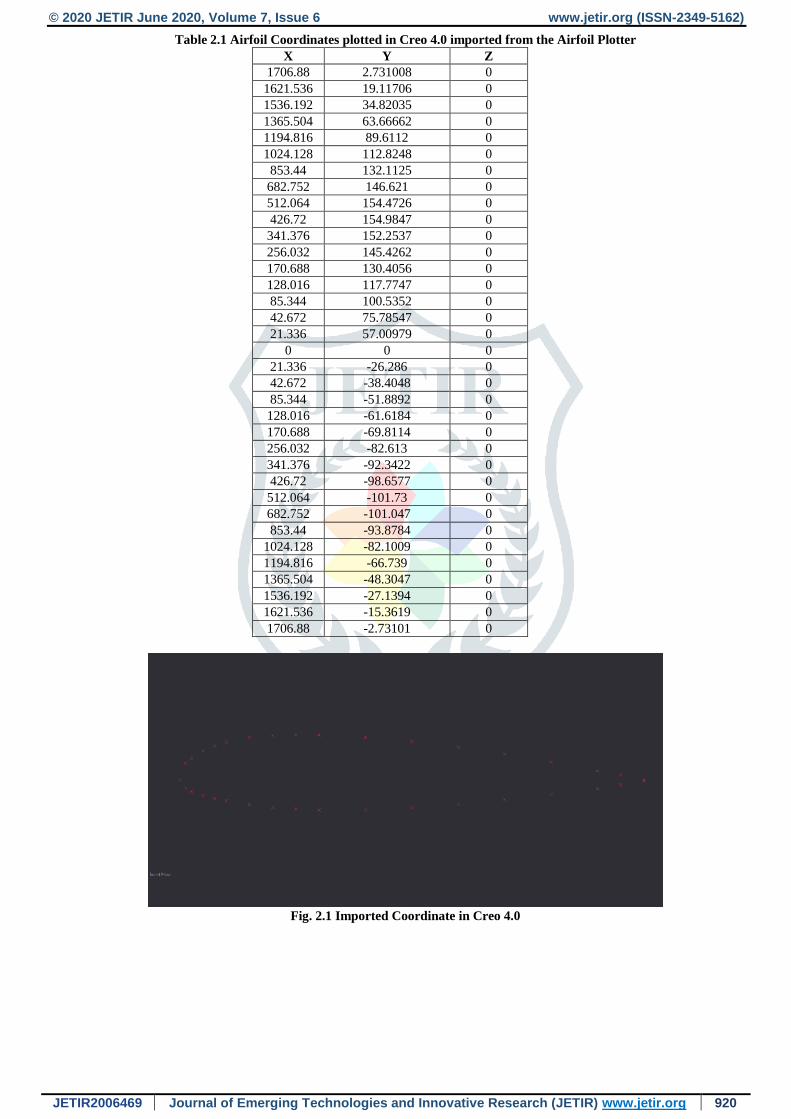
2.1 Importing the Coordinates of NACA 23015
The following airfoil coordinates of the NACA 23015 airfoil are imported from the airfoil plotter in the form of (.CSV) format
in the Creo 4.0 software.
© 2020 JETIR June 2020, Volume 7, Issue 6 www.jetir.org (ISSN-2349-5162)
JETIR2006469 Journal of Emerging Technologies and Innovative Research (JETIR) www.jetir.org 920
Table 2.1 Airfoil Coordinates plotted in Creo 4.0 imported from the Airfoil Plotter
X Y Z
1706.88 2.731008 0
1621.536 19.11706 0
1536.192 34.82035 0
1365.504 63.66662 0
1194.816 89.6112 0
1024.128 112.8248 0
853.44 132.1125 0
682.752 146.621 0
512.064 154.4726 0
426.72 154.9847 0
341.376 152.2537 0
256.032 145.4262 0
170.688 130.4056 0
128.016 117.7747 0
85.344 100.5352 0
42.672 75.78547 0
21.336 57.00979 0
0 0 0
21.336 -26.286 0
42.672 -38.4048 0
85.344 -51.8892 0
128.016 -61.6184 0
170.688 -69.8114 0
256.032 -82.613 0
341.376 -92.3422 0
426.72 -98.6577 0
512.064 -101.73 0
682.752 -101.047 0
853.44 -93.8784 0
1024.128 -82.1009 0
1194.816 -66.739 0
1365.504 -48.3047 0
1536.192 -27.1394 0
1621.536 -15.3619 0
1706.88 -2.73101 0
Fig. 2.1 Imported Coordinate in Creo 4.0
© 2020 JETIR June 2020, Volume 7, Issue 6 www.jetir.org (ISSN-2349-5162)
JETIR2006469 Journal of Emerging Technologies and Innovative Research (JETIR) www.jetir.org 921
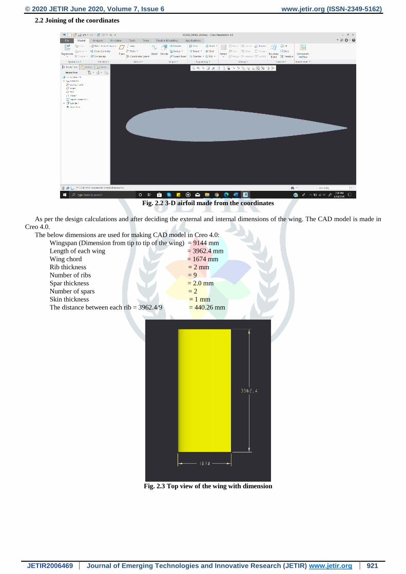
2.2 Joining of the coordinates
Fig. 2.2 3-D airfoil made from the coordinates
As per the design calculations and after deciding the external and internal dimensions of the wing. The CAD model is made in
Creo 4.0.
The below dimensions are used for making CAD model in Creo 4.0:
Wingspan (Dimension from tip to tip of the wing) = 9144 mm
Length of each wing = 3962.4 mm
Wing chord = 1674 mm
Rib thickness = 2 mm
Number of ribs = 9
Spar thickness = 2.0 mm
Number of spars = 2
Skin thickness = 1 mm
The distance between each rib = 3962.4/9 = 440.26 mm
Fig. 2.3 Top view of the wing with dimension
© 2020 JETIR June 2020, Volume 7, Issue 6 www.jetir.org (ISSN-2349-5162)
JETIR2006469 Journal of Emerging Technologies and Innovative Research (JETIR) www.jetir.org 922
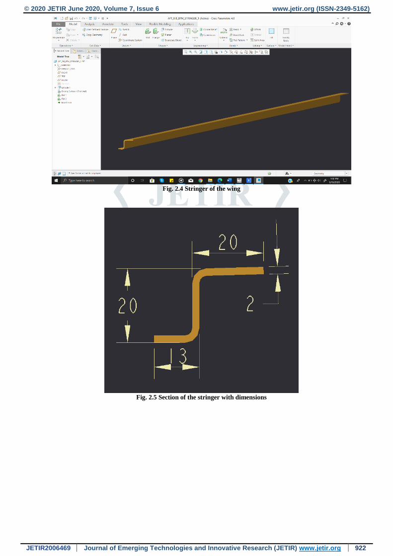
Fig. 2.4 Stringer of the wing
Fig. 2.5 Section of the stringer with dimensions
© 2020 JETIR June 2020, Volume 7, Issue 6 www.jetir.org (ISSN-2349-5162)
JETIR2006469 Journal of Emerging Technologies and Innovative Research (JETIR) www.jetir.org 923
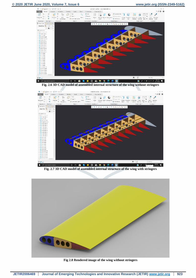
Fig. 2.6 3D CAD model of assembled internal structure of the wing without stringers
Fig. 2.7 3D CAD model of assembled internal structure of the wing with stringers
Fig 2.8 Rendered image of the wing without stringers
© 2020 JETIR June 2020, Volume 7, Issue 6 www.jetir.org (ISSN-2349-5162)
JETIR2006469 Journal of Emerging Technologies and Innovative Research (JETIR) www.jetir.org 924
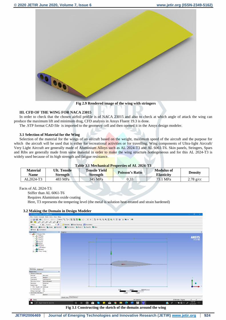
Fig 2.9 Rendered image of the wing with stringers
III. CFD OF THE WING FOR NACA 23015
In order to check that the chosen airfoil profile is of NACA 23015 and also to check at which angle of attack the wing can
produce the maximum lift and minimum drag, CFD analysis in Ansys Fluent 19.3 is done.
The .STP format CAD file is imported to the geometry cell and then opened it in the Ansys design modeler.
3.1 Selection of Material for the Wing
Selection of the material for the wings of an aircraft based on the weight, maximum speed of the aircraft and the purpose for
which the aircraft will be used that is either for recreational activities or for travelling. Wing components of Ultra-light Aircraft/
Very Light Aircraft are generally made of Aluminium Alloys such as AL 2024-T3 and AL 6061-T6. Skin panels, Stringers, Spars
and Ribs are generally made from same material in order to make the wing structure homogeneous and for this AL 2024-T3 is
widely used because of its high strength and fatigue resistance.
Table 3.1 Mechanical Properties of AL 2024-T3
Material
Name
Ult. Tensile
Strength
Tensile Yield
Strength Poisson’s Ratio
Modulus of
Elasticity Density
AL2024-T3 483 MPa 345 MPa 0.33 73.1 MPa 2.78 g/cc
Facts of AL 2024-T3:
Stiffer than AL 6061-T6
Requires Aluminium oxide coating
Here, T3 represents the tempering level (the metal is solution heat-treated and strain hardened)
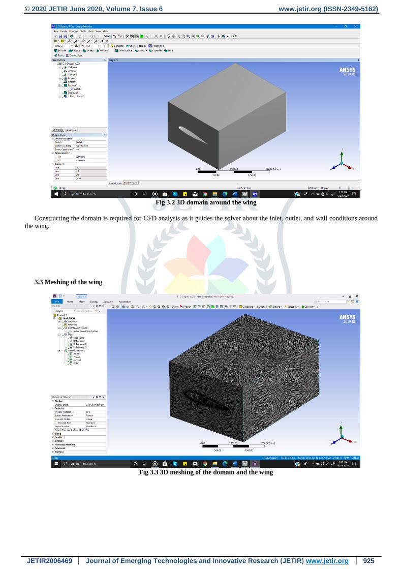
3.2 Making the Domain in Design Modeler
Fig 3.1 Constructing the sketch of the domain around the wing
© 2020 JETIR June 2020, Volume 7, Issue 6 www.jetir.org (ISSN-2349-5162)
JETIR2006469 Journal of Emerging Technologies and Innovative Research (JETIR) www.jetir.org 925
Fig 3.2 3D domain around the wing
Constructing the domain is required for CFD analysis as it guides the solver about the inlet, outlet, and wall conditions around
the wing.
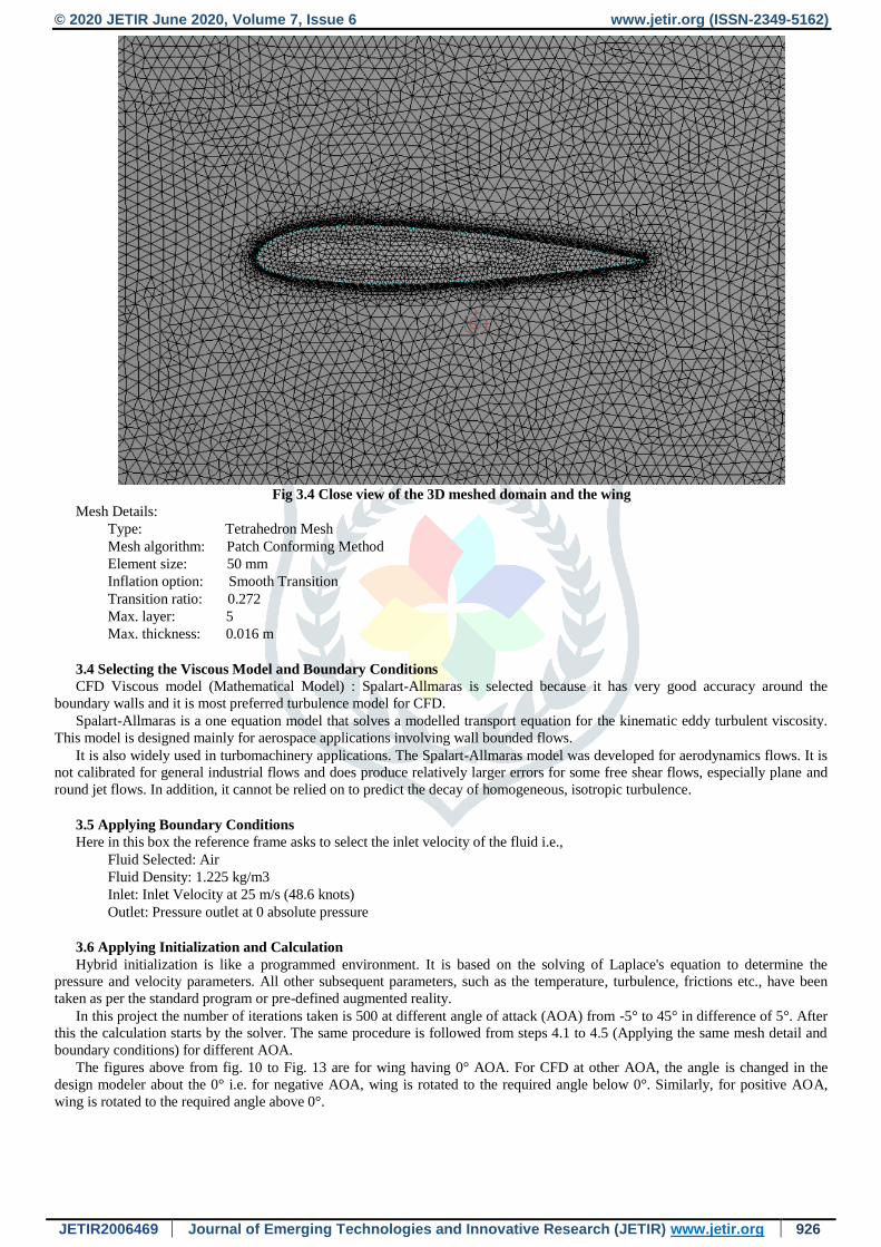
3.3 Meshing of the wing
Fig 3.3 3D meshing of the domain and the wing
© 2020 JETIR June 2020, Volume 7, Issue 6 www.jetir.org (ISSN-2349-5162)
JETIR2006469 Journal of Emerging Technologies and Innovative Research (JETIR) www.jetir.org 926
Fig 3.4 Close view of the 3D meshed domain and the wing
Mesh Details:
Type: Tetrahedron Mesh
Mesh algorithm: Patch Conforming Method
Element size: 50 mm
Inflation option: Smooth Transition
Transition ratio: 0.272
Max. layer: 5
Max. thickness: 0.016 m
3.4 Selecting the Viscous Model and Boundary Conditions
CFD Viscous model (Mathematical Model) : Spalart-Allmaras is selected because it has very good accuracy around the
boundary walls and it is most preferred turbulence model for CFD.
Spalart-Allmaras is a one equation model that solves a modelled transport equation for the kinematic eddy turbulent viscosity.
This model is designed mainly for aerospace applications involving wall bounded flows.
It is also widely used in turbomachinery applications. The Spalart-Allmaras model was developed for aerodynamics flows. It is
not calibrated for general industrial flows and does produce relatively larger errors for some free shear flows, especially plane and
round jet flows. In addition, it cannot be relied on to predict the decay of homogeneous, isotropic turbulence.
3.5 Applying Boundary Conditions
Here in this box the reference frame asks to select the inlet velocity of the fluid i.e.,
Fluid Selected: Air
Fluid Density: 1.225 kg/m3
Inlet: Inlet Velocity at 25 m/s (48.6 knots)
Outlet: Pressure outlet at 0 absolute pressure
3.6 Applying Initialization and Calculation
Hybrid initialization is like a programmed environment. It is based on the solving of Laplace's equation to determine the
pressure and velocity parameters. All other subsequent parameters, such as the temperature, turbulence, frictions etc., have been
taken as per the standard program or pre-defined augmented reality.
In this project the number of iterations taken is 500 at different angle of attack (AOA) from -5° to 45° in difference of 5°. After
this the calculation starts by the solver. The same procedure is followed from steps 4.1 to 4.5 (Applying the same mesh detail and
boundary conditions) for different AOA.
The figures above from fig. 10 to Fig. 13 are for wing having 0° AOA. For CFD at other AOA, the angle is changed in the
design modeler about the 0° i.e. for negative AOA, wing is rotated to the required angle below 0°. Similarly, for positive AOA,
wing is rotated to the required angle above 0°.

© 2020 JETIR June 2020, Volume 7, Issue 6 www.jetir.org (ISSN-2349-5162)
JETIR2006469 Journal of Emerging Technologies and Innovative Research (JETIR) www.jetir.org 927
3.7 Results of CFD at Different Angle of Attack (AOA)
Fig 3.5 Velocity contour at -20-degree Angle of Attack
Fig 3.6 Pressure contour at -20° Angle of Attack
Fig 3.7 Velocity contour at -5° Angle of Attack
© 2020 JETIR June 2020, Volume 7, Issue 6 www.jetir.org (ISSN-2349-5162)
JETIR2006469 Journal of Emerging Technologies and Innovative Research (JETIR) www.jetir.org 928
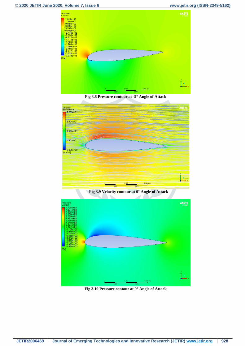
Fig 3.8 Pressure contour at -5° Angle of Attack
Fig 3.9 Velocity contour at 0° Angle of Attack
Fig 3.10 Pressure contour at 0° Angle of Attack
© 2020 JETIR June 2020, Volume 7, Issue 6 www.jetir.org (ISSN-2349-5162)
JETIR2006469 Journal of Emerging Technologies and Innovative Research (JETIR) www.jetir.org 929
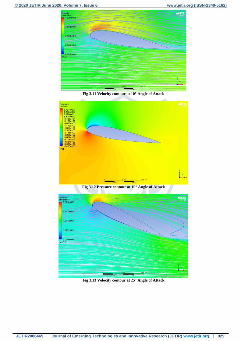
Fig 3.11 Velocity contour at 10° Angle of Attack
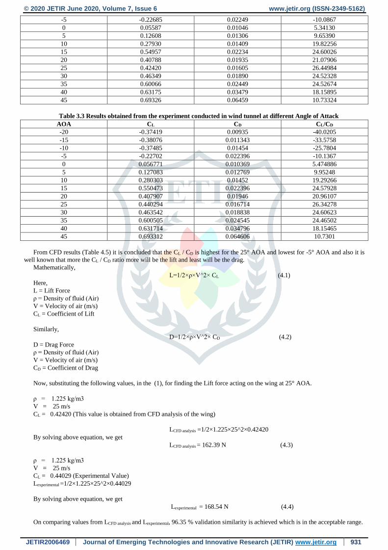
Fig 3.12 Pressure contour at 10° Angle of Attack
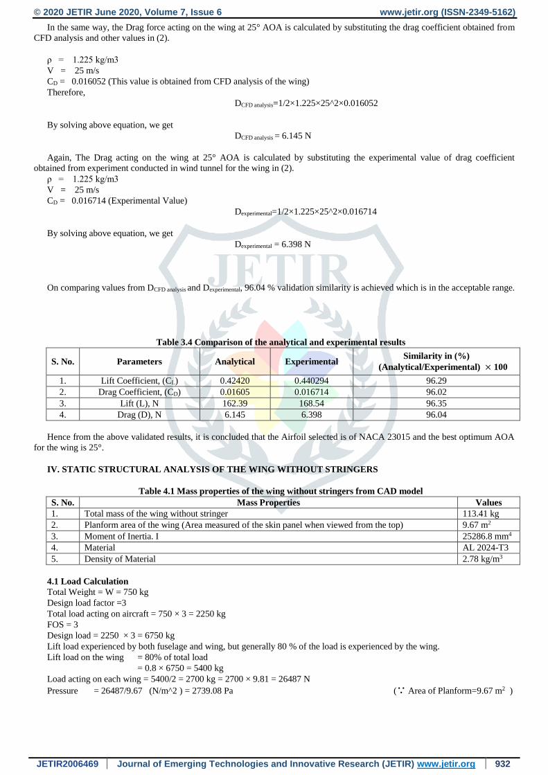
Fig 3.13 Velocity contour at 25° Angle of Attack

© 2020 JETIR June 2020, Volume 7, Issue 6 www.jetir.org (ISSN-2349-5162)
JETIR2006469 Journal of Emerging Technologies and Innovative Research (JETIR) www.jetir.org 930
Fig 3.14 Pressure contour at 25° Angle of Attack
Fig 3.15 Velocity contour at 45° Angle of Attack
Fig 3.16 Pressure contour at 45° Angle of Attack
From the above figures it is concluded that wing having AOA above 0° produces more effective lift as compared to the wing
having less than 0° AOA.
Values of Lift coefficient and drag coefficient obtained from CFD at different AOA are given below.
Table 3.2 Result obtained from the CFD of the wing at Different Angle of Attack
AOA CL CD CL/CD
-20 -0.36385 0.00926 -39.2926
-15 -0.39075 0.01128 -34.6409
-10 -0.38564 0.01354 -28.4815
© 2020 JETIR June 2020, Volume 7, Issue 6 www.jetir.org (ISSN-2349-5162)
JETIR2006469 Journal of Emerging Technologies and Innovative Research (JETIR) www.jetir.org 931
-5 -0.22685 0.02249 -10.0867
0 0.05587 0.01046 5.34130
5 0.12608 0.01306 9.65390
10 0.27930 0.01409 19.82256
15 0.54957 0.02234 24.60026
20 0.40788 0.01935 21.07906
25 0.42420 0.01605 26.44984
30 0.46349 0.01890 24.52328
35 0.60066 0.02449 24.52674
40 0.63175 0.03479 18.15895
45 0.69326 0.06459 10.73324
Table 3.3 Results obtained from the experiment conducted in wind tunnel at different Angle of Attack
AOA CL CD CL/CD
-20 -0.37419 0.00935 -40.0205
-15 -0.38076 0.011343 -33.5758
-10 -0.37485 0.01454 -25.7804
-5 -0.22702 0.022396 -10.1367
0 0.056771 0.010369 5.474886
5 0.127083 0.012769 9.95248
10 0.280303 0.01452 19.29266
15 0.550473 0.022396 24.57928
20 0.407907 0.01946 20.96107
25 0.440294 0.016714 26.34278
30 0.463542 0.018838 24.60623
35 0.600505 0.024545 24.46502
40 0.631714 0.034796 18.15465
45 0.693312 0.064606 10.7301
From CFD results (Table 4.5) it is concluded that the CL / CD is highest for the 25° AOA and lowest for -5° AOA and also it is
well known that more the CL / CD ratio more will be the lift and least will be the drag.
Mathematically,
L=1/2×ρ×V^2× CL (4.1)
Here,
L = Lift Force
ρ = Density of fluid (Air)
V = Velocity of air (m/s)
CL = Coefficient of Lift
Similarly,
D=1/2×ρ×V^2× CD (4.2)
D = Drag Force
ρ = Density of fluid (Air)
V = Velocity of air (m/s)
CD = Coefficient of Drag
Now, substituting the following values, in the (1), for finding the Lift force acting on the wing at 25° AOA.
ρ = 1.225 kg/m3
V = 25 m/s
CL = 0.42420 (This value is obtained from CFD analysis of the wing)
LCFD analysis =1/2×1.225×25^2×0.42420
By solving above equation, we get
LCFD analysis = 162.39 N (4.3)
ρ = 1.225 kg/m3
V = 25 m/s
CL = 0.44029 (Experimental Value)
Lexperimental =1/2×1.225×25^2×0.44029
By solving above equation, we get
Lexperimental = 168.54 N (4.4)
On comparing values from LCFD analysis and Lexperimental, 96.35 % validation similarity is achieved which is in the acceptable range.
© 2020 JETIR June 2020, Volume 7, Issue 6 www.jetir.org (ISSN-2349-5162)
JETIR2006469 Journal of Emerging Technologies and Innovative Research (JETIR) www.jetir.org 932
In the same way, the Drag force acting on the wing at 25° AOA is calculated by substituting the drag coefficient obtained from
CFD analysis and other values in (2).
ρ = 1.225 kg/m3
V = 25 m/s
CD = 0.016052 (This value is obtained from CFD analysis of the wing)
Therefore,
DCFD analysis=1/2×1.225×25^2×0.016052
By solving above equation, we get
DCFD analysis = 6.145 N
Again, The Drag acting on the wing at 25° AOA is calculated by substituting the experimental value of drag coefficient
obtained from experiment conducted in wind tunnel for the wing in (2).
ρ = 1.225 kg/m3
V = 25 m/s
CD = 0.016714 (Experimental Value)
Dexperimental=1/2×1.225×25^2×0.016714
By solving above equation, we get
Dexperimental = 6.398 N
On comparing values from DCFD analysis and Dexperimental, 96.04 % validation similarity is achieved which is in the acceptable range.
Table 3.4 Comparison of the analytical and experimental results
S. No. Parameters Analytical Experimental Similarity in (%)
(Analytical/Experimental) × 100
1. Lift Coefficient, (CL) 0.42420 0.440294 96.29
2. Drag Coefficient, (CD) 0.01605 0.016714 96.02
3. Lift (L), N 162.39 168.54 96.35
4. Drag (D), N 6.145 6.398 96.04
Hence from the above validated results, it is concluded that the Airfoil selected is of NACA 23015 and the best optimum AOA
for the wing is 25°.
IV. STATIC STRUCTURAL ANALYSIS OF THE WING WITHOUT STRINGERS
Table 4.1 Mass properties of the wing without stringers from CAD model
S. No. Mass Properties Values
1. Total mass of the wing without stringer 113.41 kg
2. Planform area of the wing (Area measured of the skin panel when viewed from the top) 9.67 m2
3. Moment of Inertia. I 25286.8 mm4
4. Material AL 2024-T3
5. Density of Material 2.78 kg/m3
4.1 Load Calculation
Total Weight = W = 750 kg
Design load factor =3
Total load acting on aircraft = 750 × 3 = 2250 kg
FOS = 3
Design load = 2250 × 3 = 6750 kg
Lift load experienced by both fuselage and wing, but generally 80 % of the load is experienced by the wing.
Lift load on the wing = 80% of total load
= 0.8 × 6750 = 5400 kg
Load acting on each wing = 5400/2 = 2700 kg = 2700 × 9.81 = 26487 N
Pressure = 26487/9.67 (N/m^2 ) = 2739.08 Pa (∵ Area of Planform=9.67 m2 )

© 2020 JETIR June 2020, Volume 7, Issue 6 www.jetir.org (ISSN-2349-5162)
JETIR2006469 Journal of Emerging Technologies and Innovative Research (JETIR) www.jetir.org 933
4.2 Meshing of the Wing
Fig. 4.1 3-D Meshed wing without stringers
Fig. 4.2 Side view of the meshed wing without stringers

© 2020 JETIR June 2020, Volume 7, Issue 6 www.jetir.org (ISSN-2349-5162)
JETIR2006469 Journal of Emerging Technologies and Innovative Research (JETIR) www.jetir.org 934
Fig. 4.3 3-D Meshed internal structure of the wing without stringers
Meshing Details:
Type: Tetrahedron Mesh
Mesh algorithm: Patch Conforming Method
Element size: 20 mm
Resolution: 7
Node: 736118
Elements: 338948
Inflation option: Smooth Transition
Transition ratio: 0.272
4.3 Application of Load (Pressure) and Fixed Support
In Aerodynamics similar to center of gravity, the concept of “Center of Pressure” is often used. It is the point where the
resultant force due to pressure passes. In other words, it is the point where total sum of a pressure acts on a body, causing a force
to act through that point.
Generally, the center of pressure acts at a point located at 55% of the total length of the wing when measured from the free end
of the wing.
Fig. 4.4 Location of the load applied (Side View)

© 2020 JETIR June 2020, Volume 7, Issue 6 www.jetir.org (ISSN-2349-5162)
JETIR2006469 Journal of Emerging Technologies and Innovative Research (JETIR) www.jetir.org 935
In this figure, the pressure applied is P = 2739.08 Pa = 0.00273908 MPa and in terms of load it is calculated as L = 26487 N, it
is acting in acting in the upward direction on the 6th rib from the right hand (Fixed end) side of the wing. While the left end is free
end and thus acts as a cantilever beam.
4.4 Results Obtained
Result for total deformation is obtained. The deformation achieved is
δAnalytical = 111.9067 mm
Fig. 4.5 Total Deformation shown by the solver (Side View)
Fig. 4.6 Various contours showing the intensity of deformation
The deformation found is maximum at the tip (Free end) and minimum at the fixed end.
V. Static Structural Analysis of the Wing with Stringers
s
Table 5.1 Mass properties of the wing with stringers from CAD model
S. No. Mass Properties Values
1. Total mass of the wing without stringer 118.70 kg
2. Planform area of the wing (Area measured of the skin panel when
viewed from the top) 9.67 m2
3. Moment of Inertia. I 58435.37 mm4
4. Material AL 2024-T3
5. Density of Material 2.78 kg/m3
© 2020 JETIR June 2020, Volume 7, Issue 6 www.jetir.org (ISSN-2349-5162)
JETIR2006469 Journal of Emerging Technologies and Innovative Research (JETIR) www.jetir.org 936
5.1 Load Calculation
The load acting on the wing is same as it was calculated in the wing without stringers
Application of Load (Pressure) and Fixed Support is same as that of in the section of the wing without stringers.
Fig. 5.1 Meshing of the Wing
Meshing Details:
Type: Tetrahedron Mesh
Mesh algorithm: Patch Conforming Method
Element size: 20 mm
Resolution: 7
Node: 8334896
Elements: 7638111
Inflation option: Smooth Transition
Transition ratio: 0.272
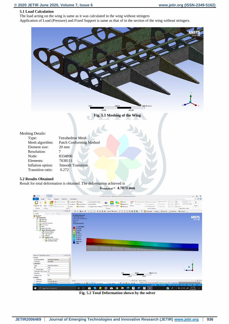
5.2 Results Obtained
Result for total deformation is obtained. The deformation achieved is
δAnalytical = 4.7873 mm
Fig. 5.2 Total Deformation shown by the solver
© 2020 JETIR June 2020, Volume 7, Issue 6 www.jetir.org (ISSN-2349-5162)
JETIR2006469 Journal of Emerging Technologies and Innovative Research (JETIR) www.jetir.org 937
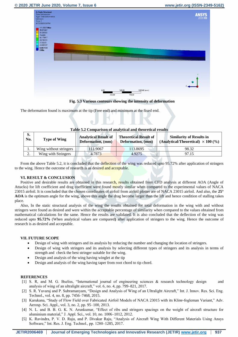
Fig. 5.3 Various contours showing the intensity of deformation
The deformation found is maximum at the tip (Free end) and minimum at the fixed end.
Table 5.2 Comparison of analytical and theoretical results
S.
No.
Type of Wing Analytical Result of
Deformation, (mm)
Theoretical Result of
Deformation, (mm)
Similarity of Results in
(Analytical/Theoretical) × 100 (%)
1. Wing without stringers 111.9067 113.8695 98.32
2. Wing with Stringers 4.7873 4.9275 97.15
From the above Table 5.2, it is concluded that the deflection of the wing was reduced upto 95.72% after application of stringers
to the wing. Hence the outcome of research is as desired and acceptable.
VI. RESULT & CONCLUSION
Positive and desirable results are obtained in this research, results obtained from CFD analysis at different AOA (Angle of
Attacks) for lift coefficient and drag coefficient were found mostly similar when compared to the experimental values of NACA
23015 airfoil. It is concluded that the chosen coordinates of airfoil from airfoil plotter are of NACA 23015 airfoil. And also, the 25°
AOA is the optimum angle for the wing, above this angle the drag become larger than the lift and hence condition of stalling takes
place.
Also, In the static structural analysis of the wing the results obtained for total deformation in the wing with and without
stringers were found as desired and were within the acceptable percentage of similarity when compared to the values obtained from
mathematical calculations for the same. Hence the results are validated. It is also concluded that the deflection of the wing was
reduced upto 95.72% (When analytical values are compared) after application of stringers to the wing. Hence the outcome of
research is as desired and acceptable.
VII. FUTURE SCOPE
Design of wing with stringers and its analysis by reducing the number and changing the location of stringers.
Design of wing with stringers and its analysis by selecting different types of stringers and its analysis in terms of
strength and check the best stringer suitable for the wing.
Design and analysis of the wing having winglet at the tip
Design and analysis of the wing having taper from root chord to tip chord.
REFERENCES
[1] S. R, and M. G. Bseliss, “International journal of engineering sciences & research technology design and
analysis of wing of an ultralight aircraft,” vol. 6, no. 4, pp. 799–821, 2017.
[2] S. R. Yuvaraj and P. Subramanyam, “Design and Analysis of Wing of an Ultralight Aircraft,” Int. J. Innov. Res. Sci. Eng.
Technol., vol. 4, no. 8, pp. 7456–7468, 2015.
[3] Karukana, “Study of Flow Field over Fabricated Airfoil Models of NACA 23015 with its Kline-fogleman Variant,” Adv.
Aerosp. Sci. Appl., vol. 3, no. 2, pp. 95–100, 2013.
[4] N. L. and B. B. G. K. N. Arunkumar, “Effect of ribs and stringers spacings on the weight of aircraft structure for
aluminium material,” J. Appl. Sci., vol. 10, no. 1006–1012, 2012.
[5] K. Ravindra, P. V. D. Raju, and P. Divakar Raju, “Analysis of Aircraft Wing With Different Materials Using Ansys
Software,” Int. Res. J. Eng. Technol., pp. 1280–1285, 2017.
© 2020 JETIR June 2020, Volume 7, Issue 6 www.jetir.org (ISSN-2349-5162)
JETIR2006469 Journal of Emerging Technologies and Innovative Research (JETIR) www.jetir.org 938
[6] S. Kumar Das and S. Roy, “Finite element analysis of aircraft wing using carbon fiber reinforced polymer and glass fiber
reinforced polymer.,” IOP Conf. Ser. Mater. Sci. Eng., vol. 402, no. 1, 2018.
[7] Fundamentals of Aerodynamics by J. D. Anderson
[8] Aircraft Design: A Conceptual Approach by Daniel P. Raymer
[9] Fundamentals of Aircraft and Airship Design Vol-1 by Leland M. Nicolai and Grant E. Carichner
[10] A Wind-tunnel Investigation of an Ultra-light Wing and Ultra-light Aircraft by Wael Khaddage
[11] Analysis of Dynamic Flight Loads by Natascha Jansson
.