© 2016 Marine Frontier @ UniKL MIMET’S TECHNICAL BULLETIN ...
116
Transcript of © 2016 Marine Frontier @ UniKL MIMET’S TECHNICAL BULLETIN ...


© 2016 Marine Frontier @ UniKL MIMET’S TECHNICAL BULLETIN. This publi-
cation is copyright under Malaysian Institute of Marine Engineering Technology Uni-
versiti Kuala Lumpur.
All rights reserved.
No part of this publication may be reproduced, stored in a retrieval system or transmit-
ted without the prior permission of the copyright owner. Permission is not, however,
required to copy abstracts of papers or of articles on condition that a full reference to
the source is shown.
Published by:
UniKL MIMET
Dataran Industri Teknologi Kejuruteraan Marin
Bandar Teknologi Maritim
Jalan Pantai Remis
32200 Lumut
Perak Darul Ridzuan
+(605)- 6909000(Phone)
+(605)-6909091(Fax)
http://www.mimet.edu.my
MIMET’S TECHNICAL BULLETIN VOLUME 7 EDITION 2 2016
MARINE FRONTIER
MIMET’S TECHNICAL BULLETIN VOLUME 7 EDITION 2 2016
MARINE FRONTIER

MIMET’S TECHNICAL BULLETIN VOLUME 7 EDITION 2 2016
MARINE FRONTIER
MIMET’S TECHNICAL BULLETIN VOLUME 7 EDITION 2 2016
MARINE FRONTIER
MESSAGE FROM ASSOC. PROF. ZAINORIN MOHAMAD
THE CHIEF EDITOR OF MARINE FRONTIER
i
MANAGING A SHIPYARD FROM A LOCAL PERSPECTIVE by AZIZ ABDULLAH
1-16
WIND TURBINE PARAMETERS CONFIGURATION STUDY IN DERIVING BEST POWER OUTPUT FOR SHIP’S APPLICATION by AZIZ ABDULLAH
17-30
BUSINESS ETHICS IN MALAYSIA by AZIZ ABDULLAH 31-41
DEMOGRAPHIC STUDY ON UNIKL MIMET’S STUDENT (BACHELOR)
ON MATHEMATIC ACHIEVEMENT by SHAIFUL BAKRI ISMAIL 42-52
DEVELOPMENT OF NEW CONCEPT OF RUDDER SYSTEM AND FIN CONTROLLER FOR MINI AUTONOMOUS UNDERWATER VEHICLE
(AUV) by NOORAZLINA M. SALIH
53-58
THE NEW CONCEPTUAL DESIGN OF TRIM TANK SYSTEM FOR MINI AUTONOMOUS UNDERWATER VEHICLE (AUV) by NOORAZLINA M.
SALIH
59-65
A DESIGN OF REGULATING AND COMPENSATING TANK SYSTEM FOR
MODULAR AUTONOMOUS UNDERWATER VEHICLE (AUV) by NOORA-
ZLINA M. SALIH
66-73
DESIGN OF INTEGRATED FLUID PARAMETRIC ANALYSIS WORKBENCH by M.A ISHAK
74-102
DETERMINATION AND FATIGUE STRENGTH OF ALUMUNIUM SWATH
MODEL IN by MAZLAN MUSLIM
COMPLIANCE WITH CLASSIFICATION RULES
103-
110
INSIDE THIS ISSUE:
CHIEF EDITOR:
Assoc. Prof. Zainorin Mohamad
EXECUTIVE EDITOR:
Dr. Puteri Zarina Megat Khalid / Mrs. Fauziah Ab
Rahman
EDITORS:
Assoc. Prof. Cmdr. (Rtd.) Dr. Aminuddin Mohd Arof
Assoc. Prof. Dr. Mohd Yuzri Mohd Yusop
Assoc. Prof. Ir. Dr. Md Salim Kamil
Mrs. Aminatul Hawa Yahaya
Mr. Aziz Abdullah
Mr. Hamdan Nurudin
Ms. Shahida Ishak
Mrs. Hanisah Johor
Mrs. Shareen Adleena Shamsuddin
Mrs. Fatin Zawani Zainal Azaim
Mrs. Zaifulrizal Zainol
EDITORIAL MEMBERS:
Mrs. Norfadhlina Khalid
Mrs. Puteri Zirwatul Nadila Binti Megat Zamanhuri
Mrs. Nor Hafidah Haliah
GRAPHIC EDITORS:
Mr. Mohd Fadzly Abdul Aziz
EDITORIAL
MIMET’S TECHNICAL BULLETIN VOLUME 7 EDITION 2 2016
MARINE FRONTIER
MIMET’S TECHNICAL BULLETIN VOLUME 7 EDITION 2 2016
MARINE FRONTIER
MESSAGE FROM
Assoc. Prof. Zainorin Mohamad
The Chief Editor of Marine Frontier
In the Name of Allah, the Most Gracious and Most Merciful.
I would like to take this opportunity to wish a very happy and prosperous new year to all
readers and it is my delight to once again welcome readers to this 2nd edition of 2016 Marine Fron-
tier.
In this issue, Marine Frontier encompass studies on shipyard management from a local per-
spective, wind turbine parameters configuration study, development of new concept of rudder sys-
tem and fin controller for mini autonomous underwater vehicle (AUV), the new conceptual design
of trim tank system for mini autonomous underwater vehicle (AUV), a design of regulating and
compensating tank system for modular autonomous underwater vehicle (AUV), design of integrat-
ed fluid parametric analysis workbench and determination of fluid dynamics and fatigue strength
of Aluminium SWATH model in compliance with classification rules. Also featured in this issue,
under the teaching and learning cluster are demographic study of students on Mathematics
achievement and business ethics in Malaysia. I hope the papers shared in this issue will enable
other researchers to generate interests and develop new ideas that will enhance existing studies and
research works.
As the number of postgraduate students and PhD holders increase, a more structured ap-
proach to research and innovation activities in UniKL MIMET is being adopted. Distinctly, a
number of research clusters is being developed. In particular, the underwater marine design and
technology cluster is expected to be established soon to consolidate and better managed all related
studies. In addition, collaborations with local and foreign universities and industry partners are
further encouraged to enable joint university and joint industry research papers to be included in
future issues of Marine Frontier.
i
ABSTRACT
A shipyard is an entity involved in activities such as shipbuilding, ship repair, ship’s modification
and upgrading, and other similar marine related works. Managing these activities requires special
skills and knowledge. In a nut shell, to manage a shipyard would require managing its people, their
activities and ensuring positive returns on the costs spent. Hence, managing a shipyard would re-
quire having an effective shipyard’s organizational structure and its management approach, having
an effective shipyard layout that is conducive to smooth materials storage and handling approach,
as well as having an efficient ship handling facilities. Additionally, an effective shipyard manage-
ment would also require focus on areas such as an efficient project management approach to meet
the requirements for a balanced organizational infrastructural loading.
Keywords: Competitiveness, organizational structure, ship handling facilities, SWOT, ship-
yard layout, safety.
MANAGING A SHIPYARD FROM A LOCAL PERSPECTIVE
AZIZ ABDULLAH
Section of Marine Construction&Maintenance Technology, Malaysian Institute of Marine
Engineering Technology,
Universiti Kuala Lumpur, 32200 LUMUT, Perak, Malaysia
___________________________________________
Corresponding author: [email protected]
MIMET’S TECHNICAL BULLETIN VOLUME 7 EDITION 2 2016
MARINE FRONTIER
MIMET’S TECHNICAL BULLETIN VOLUME 7 EDITION 2 2016
MARINE FRONTIER 1

INTRODUCTION
Managing a shipyard is a business concern. A business sustainability is determined, among
others, by its ability to remain competitive. Losing the competition with other key players would
shorten its business life. This paper will attempt to reflect on the local shipyard industry by dwell-
ing into some primary factors that should contribute towards making a shipyard competitive,
while not discounting the importance of other secondary aspects that are not mentioned in this
paper. These basic primary perspectives that are commonly found in local shipyards, are based on
author’s own observations and industrial experience, namely an effective shipyard organizational
structure and management approach, organizational safety and relevant labor laws, shipyard lay-
out, materials storage and handling, ship handling facilities, project management and organiza-
tional infrastructural loading.
PROBLEM STATEMENT
Shipyards having poor management approach often find themselves not making positive
returns. They are often too engrossed in getting projects and completing the projects on time,
while neglecting the basic principles of good shipyard management. Having many projects in
hand usually do not reflect a good company bottom line. Cost escalations or over runs due to non-
compliance of good shipyard management usually reduce a shipyard’s profit. Most shipyards as-
pire to continually make good returns while having a positive understanding of what goes into
making those returns.
METHODOLOGY
This study embraced an observational approach that relates to author’s own experience in the
shipyard industry. Relevant literatures were reviewed that helped lend credibility to author’s find-
ings as well as to provide better insights into the various aspects of shipyard management.
MIMET’S TECHNICAL BULLETIN VOLUME 7 EDITION 2 2016
MARINE FRONTIER
MIMET’S TECHNICAL BULLETIN VOLUME 7 EDITION 2 2016
MARINE FRONTIER 2

ORGANISATIONAL STRUCTURE AND MANAGEMENT APPROACH
There are many factors that contribute towards a shipyard’s competitiveness. Among them
are, firstly, an effective organizational structure and management approach. Organizations must be
seen to be dynamic to sense the need for improved lines of communication within the organiza-
tional structure, with less hierarchical obstacles. Thus, an organizational structure must be as con-
temporary, horizontal or flatten as possible, that eases communication flow to help avoid delays in
decision making. However, most organizational structures are still the traditional or vertical type
(multi-layered) most likely to breed unnecessary power-distance, unnecessary bureaucratic red
tape or, plain inefficiency (Figure 1). Traditions die hard, and in most organizations it is still the
norm to have the conventional vertical top-bottom type of structure.
The right management approach also plays an important role in making a shipyard
competitive. The optimal approach, among others, calls for a sense of dynamism, both in the man-
agement as well as workers. The ability of management and workers to work together synergisti-
cally towards achieving a high state of competitiveness would help determine the success or fail-
ure of a shipyard in achieving its mission and vision while maintaining its business sustainability.
The common management principles of Planning, Organizing, Leading and Controlling (Robbins
et. al, 2007) that have long been embraced by organizations worldwide should form the basis for
an effective management approach by shipyards. Shipyards can no longer remain competitive by
just dragging on with the times. It has to be dynamic and transformative to move forward with the
times. Operational managers should be able to effectively plan, organize, lead and control daily
operations that may include all aspects of shipyard management, including effective managing of
all shipbuilding and ship repair projects that would also include early planning of infrastructural
loading to ensure a shipyard is not overly loaded on its infrastructural capacity with regards to
managing of projects, thus leaving the strategic vision to top management to worry about.
MIMET’S TECHNICAL BULLETIN VOLUME 7 EDITION 2 2016
MARINE FRONTIER
MIMET’S TECHNICAL BULLETIN VOLUME 7 EDITION 2 2016
MARINE FRONTIER 3

Figure 1. A typical shipyard organizational structure
OCCUPATIONAL SAFETY AND HEALTH
The second factor that may contribute towards making a shipyard competitive is having an
organization that has a great concern for occupational safety and health. This is an area that is of-
ten overlooked by many organizations, until it is too late. When accidents occur, they cause un-
necessary work stoppages and these may cause delays to planned work schedules that disrupt a
shipyard’s contractual obligations. When these obligations are breached, penalties or compensa-
tions must be borne by shipyard. These penalties may reduce profits, hence shipyards may not be
making the necessary positive returns as they should be, thus having less returns would result in
making them less competitive in the business.
MIMET’S TECHNICAL BULLETIN VOLUME 7 EDITION 2 2016
MARINE FRONTIER
MIMET’S TECHNICAL BULLETIN VOLUME 7 EDITION 2 2016
MARINE FRONTIER 4
Thus, compliance with the Occupational Safety and Health Act (OSHA 1994) that provides
regulations pertaining to protection on safety and health for work activities in all economic sectors
is a must by a shipyard that is continually exposed to all kinds of hazards at its work place. Under
Section 15 (1) and (2) Occupational Safety and Health Act 1994, employers have a duty to ensure,
as far as practicable, that employees are not exposed to any hazard at the work place.
LABOR LAWS OF MALAYSIA
The third factor that helps ensure a shipyard is on the right course in achieving its
competitiveness goals is with regards to compliance of the labor laws of Malaysia. When laws are
breached the costs of mitigation can be high, thus bottom lines are affected. With less profits the
subject of competitiveness can be an elusive one. When laws are complied, abided and respected,
less problems occur at the work place, hence less cost and higher profits. The three major elements
of Malaysian Labor Laws, namely the Employment Act of 1955, Trade Unions Act of 1959 and
the Industrial Relations Act of 1967 have a bearing on the effectiveness in running an organization
as dynamic and complex as a shipyard. Examples of Malaysian Labor Laws are as follows;
Hours and Wages (Employment Act)
Work hours must not exceed eight hours a day, or 48 hours a week. Overtime pay is 1.5 times
the regular hourly wage for a normal working day, twice the normal wage on rest days and
three times the regular hourly wage on public holidays, which are granted on ten occasions
throughout the year. Sick leave is granted on a seniority basis, with employees having worked
for less than two year eligible for two weeks a year, and 22 days entitled to employees having
worked for over five years.
Firing (Employment Act)
An employee can be fired if the contract of service has been violated. This includes being
absent for more than two consecutive workdays without prior approval. An employer can
otherwise fire employees in case of worker misconduct, misdemeanor offenses or negligence
at the work place. Unless notification is specified in the contract, the law stipulates that em-
ployees working less than two years need a minimum of four weeks notification, a minimum
of six weeks for two to five years of employment, and a minimum of eight weeks for employ-
ees employed for at least five years.
MIMET’S TECHNICAL BULLETIN VOLUME 7 EDITION 2 2016
MARINE FRONTIER
MIMET’S TECHNICAL BULLETIN VOLUME 7 EDITION 2 2016
MARINE FRONTIER 5

Disputes (Industrial Relations Act)
Under the Industrial Relations Act of 1967, employers and employees are encouraged to
self-regulate their mutual relationship and to try to settle differences in a civilized manner.
Government intervention comes in the form of providing a legal model if the employer and
employee model for arbitration proves not to be sufficient. If necessary, the Ministry of Hu-
man Resources can defer disputes to the Industrial Court, after which employees cannot de-
clare a strike while the dispute is being considered by the court, although "peaceful and order-
ly picketing" is permitted under the Industrial Act of 1967.
Malaysian Labor Laws are indeed crucial in maintaining stability and order in Malaysian in-
dustries. A shipyard that is plagued by workers’ unrests due to issues such as overtime pay, unfair
work-life balance, unfair work termination, conflicts between workers and management that lead
to pickets, may ultimately lead to unnecessary work stoppages, hence disruptions to project sched-
ules. Being a business entity that survives on profits, any work delays and stoppages due to
breaches in the Malaysian Labor Laws should be avoided at all costs.
SHIPYARD LAYOUT AND LOCATION
The fourth factor that helps contribute towards a shipyard’s competitiveness is pertaining to
its layout and location. The internal layout of its production floor would depend on the nature of
its work processes and nature of material flow within the confines of its parameter. It is also im-
portant to note that the choice of its location is also a determining factor of its sustainability in the
business. Thus, a modern shipyard must be well equipped to carry out the latest and most cost-
effective work approaches as compared to a conventional shipyard. This definition of being mod-
ern may refer to a shipyard’s approach, say, in shipbuilding. Current modern concept in shipbuild-
ing embraces the modular construction approach (Myra, 2009). Ships are now being designed and
constructed using the modular approach. Modules may be constructed at different specialized lo-
cations and later brought together to an erection berth for final line-up and joining. In this ap-
proach a shipyard may just focus on its specialized areas, leaving other non-core areas to be done
by other parties at other locations. Totally constructing a complete ship, from design till launch-
ing, that used to be done by a single shipyard is no longer the norm. Improved time and cost sav-
ings, better utilization of materials and specialized skills through a more effective project manage-
MIMET’S TECHNICAL BULLETIN VOLUME 7 EDITION 2 2016
MARINE FRONTIER
MIMET’S TECHNICAL BULLETIN VOLUME 7 EDITION 2 2016
MARINE FRONTIER 6

For competitive advantage and business sustainability, a modern shipyard should have cer-
tain unique or niche capabilities that are different from other shipyards of similar class, the extent
of which would depend, among others, on its financial, manpower skill and infrastructural capaci-
ty, coupled with positive complementary external factors. The types of layouts in shipyards would
depend on the production process employed. Some of the examples of layouts are as follows;
Fixed position layout.
This is appropriate when building large items such as ships that are difficult and costly to
move. Mobile work stations are located around the stationary ship.
Product layout.
This layout requires machines or work stations to be organized around the sequence of opera-
tions required to produce the ship. Product layout is typical of high volume standardized pro-
duction. An assembly line is a product layout, because assembly facilities are organized ac-
cording to the sequence of steps required to produce the item.
Process layout.
This is the most common layout for a small to medium size volume manufacturer. A process
layout groups similar machines or similar processes having similar functions. A typical pro-
cess layout would group lathes in one area, drills in one area, milling machines in one area
and so on.
Group technology layout.
This layout is based on the concept of group technology whereby machines are grouped into
machine cells, where each cell corresponds to a part family or group of part families. Each
cell may have a combination of various machines that can perform rather concurrently on a
particular unit, sub-assembly or assembly block. This is the best and most modern layout and
is applicable in the modular construction approach.
MIMET’S TECHNICAL BULLETIN VOLUME 7 EDITION 2 2016
MARINE FRONTIER
MIMET’S TECHNICAL BULLETIN VOLUME 7 EDITION 2 2016
MARINE FRONTIER 7

Thus, knowing the most appropriate layout for the particular production process employed
would help contribute towards improving production capacity that helps reduce work redundancy
and delays, hence contributing towards a higher degree of efficiency, effectiveness and competi-
tiveness in the industry. Having the most appropriate layout based on the production process em-
ployed would be an exercise in futility if the location of the shipyard does not help in attracting
customers due to various factors. Thus, in choosing for the best location for a shipyard, the follow-
ing factors must be considered, namely;
proximity to open sea
protection from the sea
availability of transportation (highway, rail, air and water transportation)
proximity to technical schools and universities.
easy access to skilled labor
easy access to materials/spares
An existing shipyard may also require further improvements when the management feels that
it is not contributing towards making it a competitive player in the industry. Hence, further studies
on its internal attributes as well as relevant external factors shall be carried out by its management.
Using a proven management tool such as a SWOT and TOWS matrix analysis (Lawrence, 2009)
may help identify the factors that make a shipyard less competitive. Results from this analysis
shall be used as a basis to improve further the shipyard’s internal layout or its position in the in-
dustry. Looking at an example of an existing shipyard (Figure 2) that is deemed not contributing
towards making it a competitive entity in the industry, we can carry out a simple exercise using
the SWOT and TOWS matrix analysis. Later on, based on findings we can recommend to the
management on how to improve further and make the shipyard more competitive.
MIMET’S TECHNICAL BULLETIN VOLUME 7 EDITION 2 2016
MARINE FRONTIER
MIMET’S TECHNICAL BULLETIN VOLUME 7 EDITION 2 2016
MARINE FRONTIER 8

Figure 2. An existing shipyard
Looking at the shipyard, obviously there are internal strengths and weaknesses in its internal lay-
out, as well as external opportunities and threats (posed by the local shipyard industry or other
competitive shipyards in the vicinity). Listing down all the critical internal strengths and weak-
nesses, as well as any external opportunities and threats, synergize them using the TOWS matrix
(Figure 3) and analyze the most possible outcome of the synergy exercise.
This finding should form the basis of our improvement plans for the shipyard. It should be
noted that this exercise must be conducted with an experienced facilitator on hand to provide guid-
ance and further understanding on issues that arise when attributes are synergized. There is no
right or wrong answer as the outcome of this exercise is merely a reflection on the level of experi-
ence and knowledge of parties involved. The level of subjectivity in the findings is indicative of
the mix of ideas, expertise, and experience available that should be fully utilized by management.
Sometimes, to lend credibility to findings and improvement plans, an organization would consult
an external party as generating ideas and improvement plans from within own resources would not
be as creative and promising.
MIMET’S TECHNICAL BULLETIN VOLUME 7 EDITION 2 2016
MARINE FRONTIER
MIMET’S TECHNICAL BULLETIN VOLUME 7 EDITION 2 2016
MARINE FRONTIER 9

Figure 3. TOWS matrix analysis
Figure 4. An improved shipyard layout
MIMET’S TECHNICAL BULLETIN VOLUME 7 EDITION 2 2016
MARINE FRONTIER
MIMET’S TECHNICAL BULLETIN VOLUME 7 EDITION 2 2016
MARINE FRONTIER 10
S W
O S1 O1
S1 O2 Max-Max
S2 O1
S2 O2
W1 O1
W1O2 Min - Max
W2 O1
W2 O2
T S1 T1
S1 T2 Max-Min
S2 T1
S2 T2
W1 T1
W1 T2 Min - Min
W2 T1
W2 T2
Some typical improvement plans (Figure 4) derived from a SWOT and TOWS matrix analysis
would be as follows;
Set up stockyard near check point to reduce travel time of plates coming in and to be
nearer to main yard. Shift sand blasting unit accordingly
Use the unutilized area to set up grit blasting/painting and CNC cutting units, thus
reducing travel time of modules/plates
Add more (or shift existing) skids nearer to main yard to reduce travel time of mod-
ules
Shift main office building to give direct access of main yard to construction bays
Shift store to north of main yard if space permits
Some of the benefits envisioned from a shipyard’s improvement plans are as follows;
Faster production line
Lesser delivery time, thus allowing for more orders
Lower man-time requirement, thus reducing man-hour costs
Use of lifting equipment is reduced (due to lesser amount of shifting of modules &
panels), hence freeing them for other better use
Lesser costs may translate into higher profit margins.
MATERIAL STORAGE AND HANDLING
The fifth factor that helps in making a shipyard competitive is in the aspect of safe, effective
and efficient materials storage and handling. Why is safe, effective and efficient materials storage
and handling crucial in making a shipyard competitive? It is common knowledge, as cited by Scott
(2013) that an ineffective system of material storage and handling in a production shop floor may
contribute towards work stoppages due to unnecessary bottlenecks caused by improper storage
and unsafe handling. Any unsafe activity in an industrial environment such as a shipyard may
lead to hazardous situations that may result in mishaps or accidents. Accidents result in disruptions
to work schedules, stoppages and delays. Delays mean extra hours and higher cost of labor, re-
works, injury claims that ultimately leads to less profits, hence making a shipyard less competitive
when most of its resources and time are spent on damage control, rather than profit making.
MIMET’S TECHNICAL BULLETIN VOLUME 7 EDITION 2 2016
MARINE FRONTIER
MIMET’S TECHNICAL BULLETIN VOLUME 7 EDITION 2 2016
MARINE FRONTIER 11

Common materials that need proper storage and handling in shipyards are, among others, compo-
site fibers, mild steel, aluminum, stainless steel, copper, brass and timber. Effective storage of
metals in a shipyard can be reflected by looking at an analogy on the effects of dissimilar metals
in a marine environment.
As we are aware, a shipyard produces structures that operate in water. When a steel ship
floats in water, it undergoes certain processes that affect its metallurgical properties. One such
effect is electrolytic corrosion that occurs due to certain dissimilar properties of a ship’s underwa-
ter hull with the sea water on which it floats. The galvanic series that show higher metals (or noble
metals) preceding the lower metals (or less noble metals) may result in electrolytic corrosion of
the less noble metal while protecting the more noble metal and this may be illustrated further by
using two dissimilar metals of a ship, the anode (normally of zinc which is sometimes called the
‘sacrificial’ anode or lower metal) and the cathode (normally the mild steel hull of a ship or higher
metal) that is submerged in seawater through which current flows from the more reactive anode to
the less reactive cathode, thereby corroding the zinc to deposit its ions on the steel hull, hence
protecting the steel hull from corrosion. The zinc, being less noble than steel in the galvanic series,
is eaten away while the cathode which is nobler in the galvanic series is always protected. How-
ever, the reaction may change depending on the type of metals used for the underwater hull and
their hierarchy in the galvanic series. Electro chemical corrosion can be prevented by proper selec-
tion of hull materials and using adequate cathodic protection.
Thus, the correct choice of metals used for underwater hull construction will determine
whether the hull is amply protected from corrosion or otherwise. This can also be related to im-
proper storage and handling of materials in a shipyard that may lead to unnecessary electrolytic
corrosion if dissimilar metals in storage are stacked together. Corrosion may occur on less noble
metals while protecting the higher metals. It is imperative that the correct mode of material stor-
age and handling in shipyards be given due attention by the shipyard management to avoid unnec-
essary losses and wastages to materials that may affect planned work schedules, quality of work
and overall production capacity. Losses due to improper storage and handling may lead to higher
replacement or remedial costs that result in reduced profits, hence loss of competitiveness.
MIMET’S TECHNICAL BULLETIN VOLUME 7 EDITION 2 2016
MARINE FRONTIER
MIMET’S TECHNICAL BULLETIN VOLUME 7 EDITION 2 2016
MARINE FRONTIER 12

SHIP HANDLING FACILITIES
The sixth factor that may help contribute towards ensuring a shipyard’s high state of
competitiveness is by having effective ship handling facilities. It is good business sense that a
shipyard must have the right and adequate facilities to handle ships that are berthed alongside its
jetty, either awaiting up-slipping or while being outfitted after down-slipping (Pelletier, 1996).
Adequate ship handling facilities is crucial to the sustainability of a shipyard’s operation because
without the necessary facilities it is seen as being handicapped and deficient in its capacity to pro-
vide much needed services to ship owners. Before entering a shipyard for services a ship needs to
be berthed while awaiting to be up-slipped or docked. A brief description of basic berthing and
docking arrangements are given below;
Berthing arrangements
Berthing arrangement refers to a place where a ship needs to tie up alongside a wharf or a
pier structure. With regards to a shipyard, a berth is a place where a ship is moored within a ship-
yard’s perimeter before or after down-slipping and usually the ship is meant to undergo pre or post
slipping works that cannot be done in the docks or on the slipway, or further outfitting works after
launching, while afloat. While berthed in the shipyard, works that require lifting operations are
usually provided for by shipside cranes and ship may be pulled conveniently to other nearby out-
fitting berths if required.
Docking arrangements
Large ships are usually launched down a slipway or flooded up in a dock where they are
built. In the case of a shipyard with a building dock the large hull blocks that comprise the ship are
assembled on a level line of building blocks which are similar to docking blocks. Building docks
tend to be shallower than graving docks as the ship is flooded up considerably lighter than the
lightship condition. The building dock very often has concrete ramps built into the head end of the
dock to allow vehicular access without the need for using cranes. The building dock is also very
wide to allow for the construction of more than one vessel at the same time. Prior to docking, a
docking plan must be made available by ship owner and given to a dock master to enable him to
plan the necessary docking arrangements with regards to correct placement of keel blocks and
bilge blocks to avoid placing them at the wrong places.
MIMET’S TECHNICAL BULLETIN VOLUME 7 EDITION 2 2016
MARINE FRONTIER
MIMET’S TECHNICAL BULLETIN VOLUME 7 EDITION 2 2016
MARINE FRONTIER 13
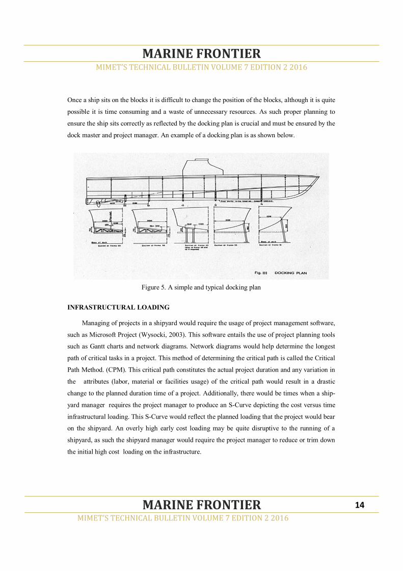
Once a ship sits on the blocks it is difficult to change the position of the blocks, although it is quite
possible it is time consuming and a waste of unnecessary resources. As such proper planning to
ensure the ship sits correctly as reflected by the docking plan is crucial and must be ensured by the
dock master and project manager. An example of a docking plan is as shown below.
Figure 5. A simple and typical docking plan
INFRASTRUCTURAL LOADING
Managing of projects in a shipyard would require the usage of project management software,
such as Microsoft Project (Wysocki, 2003). This software entails the use of project planning tools
such as Gantt charts and network diagrams. Network diagrams would help determine the longest
path of critical tasks in a project. This method of determining the critical path is called the Critical
Path Method. (CPM). This critical path constitutes the actual project duration and any variation in
the attributes (labor, material or facilities usage) of the critical path would result in a drastic
change to the planned duration time of a project. Additionally, there would be times when a ship-
yard manager requires the project manager to produce an S-Curve depicting the cost versus time
infrastructural loading. This S-Curve would reflect the planned loading that the project would bear
on the shipyard. An overly high early cost loading may be quite disruptive to the running of a
shipyard, as such the shipyard manager would require the project manager to reduce or trim down
the initial high cost loading on the infrastructure.
MIMET’S TECHNICAL BULLETIN VOLUME 7 EDITION 2 2016
MARINE FRONTIER
MIMET’S TECHNICAL BULLETIN VOLUME 7 EDITION 2 2016
MARINE FRONTIER 14
In a nut shell, infrastructural loading can be determined through the usage of an S-shaped graph as
a management tool to identify and take remedial action if a project is exerting unnecessary loading
on an organization’s resources, such as labor, man-hours or facilities. The S-Curve is meant to
assist the project management to effectively and efficiently plan scheduling of production re-
sources so that resource requirements are adequately and economically scheduled to avoid unnec-
essary loading of production capacities. An abnormally high initial cumulative man-hour loading
may indicate that manpower is overly allocated and should be spread out to avoid placing exces-
sive constraints on production capacity. Similarly, an abnormally high initial cumulative cost
loading may indicate too much cost in terms of labor and material are overly allocated early and
should be reduced or spread out to avoid placing excessive constraints on production financial
capacity of a shipyard.
CONCLUSION
Being an entity that is involved in costly activities such as shipbuilding, ship repair, ship’s
modification and upgrading, and other marine related works, consideration must be made on the
aspect of significant margins for profits. Only then would sustainability in the business be main-
tained because a business operating at cost or low profit margin attracts unnecessary risks and a
risky business is not a good venture. Managing of shipyard activities requires special skills and
knowledge. Shipyard managers must be equipped with dynamic skills and knowledge to face the
challenges in the marine industry. Losing customers due to being less competitive can be over-
come by being dynamic enough to change with the times. Factors that contribute towards making
a shipyard competitive must be continually improved and upgraded to ensure that a shipyard is
always moving with times and having a competitive advantage over its competitors. It must there-
fore strive to remain as a market leader, while establishing its core competencies in areas that can-
not be overtaken by its competitors. From the local perspective, most shipyards in Malaysia need
to keep abreast with the changes in the industry. Taking into consideration on status of all factors
that may contribute towards making the local shipyards competitive in the industry it is safe to
note that the shipyard industry is a strong contributor towards Malaysia’s transformation plans as
an industrialized nation by 2020.
MIMET’S TECHNICAL BULLETIN VOLUME 7 EDITION 2 2016
MARINE FRONTIER
MIMET’S TECHNICAL BULLETIN VOLUME 7 EDITION 2 2016
MARINE FRONTIER 15
REFERENCES
[1] Lawrence G. Fine (2009). The SWOT Analysis: Using your strengths to overcome weakness-
es, using opportunities to overcome threats. 1st edition. CreateSpace Independent Publishing
Platform.
[2] Mayra L. De La Torre (2009). A Review and Analysis of Modular Construction Practices.
Lehigh University.
[3] Occupational Safety and Health Act (OSHA 1994).
[4] Pelletier, J.L (1996). Worldwide Ship and Boat Repair Facilities: Shipyards, Repair Y ards
and Dry Dock. Marine Techniques, Augusta, USA.
[5] Robbins, S.P & Coulter, M (2007). Management. Pearson Prentice Hall.
[6] Scott B. Keller (2013). The Definitive Guide to Warehousing: Managing the Storage and han-
dling of Materials and Products in the Supply Chain. 1st edition. Pearson..
[7] Wysock, Robert K. (2003). Effective Project Management: Traditional, Adaptive, Extreme.
3rd edition. Wiley Publication, Indianopolis.
MIMET’S TECHNICAL BULLETIN VOLUME 7 EDITION 2 2016
MARINE FRONTIER
MIMET’S TECHNICAL BULLETIN VOLUME 7 EDITION 2 2016
MARINE FRONTIER 16

ABSTRACT
Wind energy is a form of renewable energy and very cost effective if properly tapped for usage. It
can be a good alternative to replace conventional sources. With the diminishing supply of fossil-
based energy, new renewable energy sources, such as wind energy, are being explored. In vertical
axis wind turbine, Savonius-rotor type has been shown to be suitable at low wind speeds. The pa-
per describes the parametric study on Savonius rotor to obtain the optimized power output in ma-
rine application. Parameters discussed are the aspect ratio of height and diameter of Savonius type
wind turbine. The Savonius wind turbine is installed on board a 50m tanker to validate the stability
of the ship. Results proved that the higher the aspect ratio will give the best power output. Never-
theless, Savonius wind turbine may not contribute as much energy as the vessel needs, hence more
studies in the future, such as on the effect of existence of end plates or effect of overlap ratio, are
needed to make sure there are different options available instead of the fossil-based energy alone
to generate power for vessels.
Keywords: Numerical analysis, Shipping Industry, Stability Analysis, Optimised Power Out-
put, Wind Turbine
MIMET’S TECHNICAL BULLETIN VOLUME 7 EDITION 2 2016
MARINE FRONTIER
MIMET’S TECHNICAL BULLETIN VOLUME 7 EDITION 2 2016
MARINE FRONTIER 17
WIND TURBINE PARAMETERS CONFIGURATION STUDY IN DERIVING BEST
POWER OUTPUT FOR SHIP’S APPLICATION
AZIZ ABDULLAH1 , SHAIFUL BAKRI2, ILIASDA MUHAMMAD3
Section of Marine Construction &Maintenance Technology, Malaysian Institute of Marine
Engineering Technology, Universiti Kuala Lumpur, 32200 LUMUT, Perak, Malaysia
Section of Technical Foundation, Malaysian Institute of Marine Engineering Technology, Univer-
siti Kuala Lumpur, 32200 LUMUT, Perak, Malaysia
Malaysian Institute of Marine Engineering Technology, Universiti Kuala Lumpur, 32200 LUMUT,
Perak, Malaysia
___________________________________________
Corresponding author: [email protected]

INTRODUCTION
Renewable energy is from natural sources that are in abundance and never deplete in supply,
such as wind power, solar power, geothermal energy and hydropower. They are called
‘renewable’ due to their continuous replenishment and availability for use over and over again.
Due to the gradual exhaustion of conventional power and increased awareness on the adverse ef-
fects to the environment, the demand for renewable energy is taking center stage. Political will by
industrialized nations is also influencing re-legislation of environmental laws to accommodate
increased usage of renewable energy. This new phenomena is being bolstered through better re-
search and application of new green technology and it is estimated that globally consumption of
renewable energy would be about 20% - 50% towards the end of this century and this would ac-
count to a net growth rate of more than 21% per year. Its application in the marine application
(such as ships) would be a far reaching foresight, as wind power is readily available and in abun-
dance.
The study was embarked to seek possibilities of tapping wind energy to power ships. What is
wind? It is basically a natural element that occurs everywhere on the globe and it blows faster over
the sea than over land. Thus, for ships this is an advantage because plying the world’s oceans
where wind is in abundance would require less stoppages for fuel. Currently, the majority of ships
use fossil fuels, such as diesels or other hydro carbon fuels. A sea journey using conventional
fuels would cost the ship owner a lot of money, ironically by using renewable energy that is
tapped for free would save the ship owner huge overhead costs and this saving can be diverted to
better maintain the machineries on board.
The scope of this study focused on parameters configuration of wind turbine to achieve best
power output for marine application. As we are aware whenever wind blows over a turbine blade
resistance will occur, thus considerations for proper design and stability of a ship would be a
strong prerequisite to realize the possibility of making this positive change to the shipping indus-
try.
LITERATURE REVIEW
To further understand the concept of wind energy and its application on ships relevant
literatures were reviewed taking into consideration on possible challenges and expected future
advancements. The reviews provided findings on which relevant theoretical methodologies were
derived and further expounded that provide better views on their relationships and possible means
MIMET’S TECHNICAL BULLETIN VOLUME 7 EDITION 2 2016
MARINE FRONTIER
MIMET’S TECHNICAL BULLETIN VOLUME 7 EDITION 2 2016
MARINE FRONTIER 18
PROBLEM STATEMENT
The general lack of awareness on the usage of alternative sources of energy, such as wind
results in application issues facing the shipping industry. Cost saving issues with regards to
implementing of related wind energy system for ships usually haunt ship owners. Hence, the issue
of readiness of the marine industry to accept change with regards to renewable energy technology
need to be resolved. This study would try to fill the gaps that may ultimately help address issues
affecting the big picture in optimizing power output using renewable energy sources for ships’
application.
SIGNIFICANCE OF RESEARCH
Further development of the shipping sector, such as in the application of renewable energy
for ships’ power requires greater insights into areas, such as in improving wind turbine parameters
for optimized power output in marine shipboard application. It is an area that certainly needs spe-
cial focus especially in this era of uncertainties with regards to the availability and sustainability
of conventional energy sources.
RESEARCH OBJECTIVES
The aim of this research is to investigate how wind turbine parameters configuration affect
the production of optimized power output, to develop the means for marine applications and to
study the stability of a vessel upon installation of wind turbine on board.
THEORETICAL ASPECTS
Savonius Wind Turbine
Air Density
Normal air density is 1.225kg/m3. The value might vary, though not much, according to
where the wind turbine is installed.
Efficiency
It is proven from the study by Ian Ross in 2010 that Savonius wind turbine can only achieve
30% out of 59.3% Betz Limit. Savonius has low efficiency, thus more input should be sought on
MIMET’S TECHNICAL BULLETIN VOLUME 7 EDITION 2 2016
MARINE FRONTIER
MIMET’S TECHNICAL BULLETIN VOLUME 7 EDITION 2 2016
MARINE FRONTIER 19
Wind Speed
Wind speed is dependent on where the wind turbine is being installed, the wind speed at sea
is higher than over land. This is due to the space of sea that has no turbulence caused by
infrastructures or high buildings. Average wind speed around Malaysian waters is 3.8m/s as re-
ported by Malaysian Meteorologist Department.
Expected RPM from Wind Speed.
From the speed of wind and diameter of wind turbine, Speed RPM from different wind speed
are gathered.
Swept Area
As the rotor turns, blades generate an imaginary surface whose projection on a vertical plane
to wind direction is called the swept area. The amount of energy produced by a wind turbine
primarily depends on the rotor area, also referred to a cross-sectional area, swept area, or intercept
area. The swept area for Savonius wind turbine can be calculated from the dimensions of the ro-
tors.
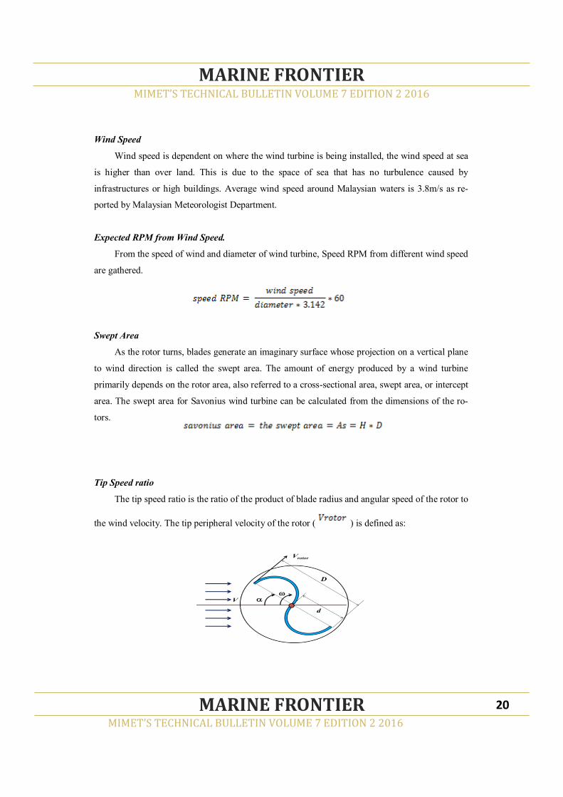
Tip Speed ratio
The tip speed ratio is the ratio of the product of blade radius and angular speed of the rotor to
the wind velocity. The tip peripheral velocity of the rotor ( ) is defined as:
MIMET’S TECHNICAL BULLETIN VOLUME 7 EDITION 2 2016
MARINE FRONTIER
MIMET’S TECHNICAL BULLETIN VOLUME 7 EDITION 2 2016
MARINE FRONTIER 20

Where:
Vrotor = the tip speed (peripheral velocity of Savonius rotor) (m/s)
ω= angular velocity of Savonius rotor (rad/sec)
d = diameter of the semi-cylindrical rotor (m)
Tip speed ratio can be expressed as:
Torque Coefficient
It is defined as the ratio between the actual torque developed by the rotor (T) and the
theoretical torque available in the wind (Tw), thus the torque coefficient (Ct) is given by:
Where:
Ct = torque coefficient
T = rotor torque (Nm)
Tw = wind available torque (Nm)
p = air density (kg/m^3)
Another concept that can be used to measure the wind turbine performance is the static
torque (Ts), which measures the self starting capability of the turbine. Static torque is defined as a
maximum value of the torque when rotor is blocked i.e. without ability to rotate. So the static
torque coefficient is given by;
MIMET’S TECHNICAL BULLETIN VOLUME 7 EDITION 2 2016
MARINE FRONTIER
MIMET’S TECHNICAL BULLETIN VOLUME 7 EDITION 2 2016
MARINE FRONTIER 21

Where,
Cts = static torque coefficient
Ts = rotor static torque (Nm)
The torque is defined as the force acting tangentially over the rotor blade, operating at a
distance of radius of rotor (d) from the center
Where,
I = moment of inertia of rotor
α = angular acceleration
The moment of inertia tells us how much energy is stored in rotating shaft or about how
much energy it will take to accelerate the shaft to a particular speed.
Generator Speed RPM
The speed RPM for generator is the rotation that can be made by generator
Power of Wind
Power of wind is how much power can the wind turbine capture.
Turbine Power
It is the power that can be made by the turbine.
MIMET’S TECHNICAL BULLETIN VOLUME 7 EDITION 2 2016
MARINE FRONTIER
MIMET’S TECHNICAL BULLETIN VOLUME 7 EDITION 2 2016
MARINE FRONTIER 22

Generated Power
The generated power is the power that can be generated by generator
Generated Energy
Generated energy from wind can be measured using the following formula;
Extracted Energy
The energy that can be extracted due to wind turbine efficiency
Ship Stability
Creating hull form
A secondary objective of this study is to determine the stability criteria of a 50m tanker
model with the wind turbine; the 50m tanker dimension is referred from other source. The basic
parameters of the tanker is referred in order to prepare the hull form using the Maxsurf modeler.
The following table is the basic parameters of the 50m tanker that has been referred to prepare the
hull form, structural design and weight calculation.
MIMET’S TECHNICAL BULLETIN VOLUME 7 EDITION 2 2016
MARINE FRONTIER
MIMET’S TECHNICAL BULLETIN VOLUME 7 EDITION 2 2016
MARINE FRONTIER 23

Table 1. Basic parameters of the vessel
The preparation procedure of the tanker model using the Maxsurf modeler begins with firstly,
setting the length units to meters and the mass (weight) to tonnes. Following that, the surface is
added where this tanker consists of three main surfaces, namely the hull, deck and transom sur-
face.
Stability Analysis
A 50m tanker model is opened in Maxsurf stability advanced application, or referred to as
Maxsurf hydromax. This is where several simulations are run and the results obtained are used in
the interpretation and analysis. It is a stability analysis of the 50m tanker model with tank, com-
partment and the wind turbine load as well. In the room definition column, the wind turbine and
components are added. Since machinery in a ship is located in specific compartment, for this case
the wind turbine and its components will be referred to as the tank.
Wind Turbine Installation
The wind turbine and its component of weight 1.278 tonnes (Vertical wind turbine) is added
to the ship. The location, vertical and horizontal distance of the tank and compartment, is not dis-
turbed except for the void space compartment is slightly reduced so that there will be a spot for
the placement of the wind turbine. The wind turbine is placed forward of the ship, after the void
space compartment.
MIMET’S TECHNICAL BULLETIN VOLUME 7 EDITION 2 2016
MARINE FRONTIER
MIMET’S TECHNICAL BULLETIN VOLUME 7 EDITION 2 2016
MARINE FRONTIER 24
Parameters Value
Ship length 50m
Ship beam 9m
Ship depth 3.65
Main engine weight 3 tonnes
Outfitting weight 1 tonne
Rudder and propeller weight 1 tonne
Design margin 10% 0.95 tonne

Total Weight
After the installation of wind turbine onboard the ship, the weight increased to about 666.2
tonnes.
RESULTS
Aspect Ratio
Inputs are gathered in Microsoft Excel Programming as shown below.
MIMET’S TECHNICAL BULLETIN VOLUME 7 EDITION 2 2016
MARINE FRONTIER
MIMET’S TECHNICAL BULLETIN VOLUME 7 EDITION 2 2016
MARINE FRONTIER 25

Summarizing from the parameters in the table below, it is obvious that the aspect ratio becomes
higher when the diameter is decreased while height is maintained, or when the height is increased
and diameter is maintained.
MIMET’S TECHNICAL BULLETIN VOLUME 7 EDITION 2 2016
MARINE FRONTIER
MIMET’S TECHNICAL BULLETIN VOLUME 7 EDITION 2 2016
MARINE FRONTIER 26
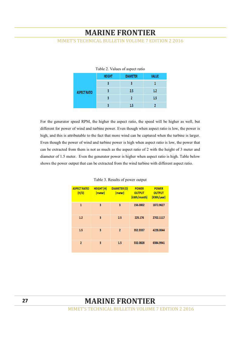
Table 2. Values of aspect ratio
For the generator speed RPM, the higher the aspect ratio, the speed will be higher as well, but
different for power of wind and turbine power. Even though when aspect ratio is low, the power is
high, and this is attributable to the fact that more wind can be captured when the turbine is larger.
Even though the power of wind and turbine power is high when aspect ratio is low, the power that
can be extracted from them is not as much as the aspect ratio of 2 with the height of 3 meter and
diameter of 1.5 meter. Even the generator power is higher when aspect ratio is high. Table below
shows the power output that can be extracted from the wind turbine with different aspect ratio.
Table 3. Results of power output
MIMET’S TECHNICAL BULLETIN VOLUME 7 EDITION 2 2016
MARINE FRONTIER
MIMET’S TECHNICAL BULLETIN VOLUME 7 EDITION 2 2016
MARINE FRONTIER 27

A lot more power can actually be extracted from wind turbine with bigger diameter and height if
the size of generator and gearing is bigger. However, the bigger the wind turbine leads to heavier
weight. The weight of the Savonius wind turbine plays a big role on the stability of the ship that
plans on installing the Savonius wind turbine on board.
Ship Stability
The results gained from the simulation of the 50m tanker model with wind turbine is as
showed and explained. Comparing to previous tank calibration, the current calibration is adjusted
by decreasing the void space and inserting the wind turbine which signifies a tank. The results of
the calibration can be observed in the figures below.
Figure 2. Perspective View
Figure 3. Plan View
MIMET’S TECHNICAL BULLETIN VOLUME 7 EDITION 2 2016
MARINE FRONTIER
MIMET’S TECHNICAL BULLETIN VOLUME 7 EDITION 2 2016
MARINE FRONTIER 28

It shows that ship is in stable condition when heeled at 20 deg, or the GZ is 0.387m. There
are slight changes for the GZ after the wind turbine load is added but the ship remains at stable
condition when heeled by an external force in still water and when heeled to a small angle of incli-
nation it returned to the upright when the force is removed. The vessel’s ability to return to up-
right after having been heeled to large angles of heel is better.
Figure 4. Graph of GZ Curve
Conclusion
Conclusively, it was found that a lot more power can actually be extracted from wind turbine
with a bigger diameter and height if the size of generator and gearing is bigger. However, the big-
ger the wind turbine often leads to heavier weight. The weight of the simulated Savonius wind
turbine plays a big role on the stability of the ship. It was also found that the vessel’s ability to
return to upright after having been heeled to large angles of heel is within acceptable limits.
The formulas used were gathered from relevant books and journals. These formulas were
selected to enable the development of an effective programme for the modelling of the wind tur-
bine system. Relevant tables and charts were produced and further elaborated to support the results
obtained. The outputs of the overall results and comparisons made were analyzed and presented
quantitatively. The analysis showed that the objectives of the study were successfully achieved.
MIMET’S TECHNICAL BULLETIN VOLUME 7 EDITION 2 2016
MARINE FRONTIER
MIMET’S TECHNICAL BULLETIN VOLUME 7 EDITION 2 2016
MARINE FRONTIER 29

In conclusion, this study had achieved its objectives namely, in investigating how wind
turbine parameters configuration affects the production of power output for marine application.
The parameters that were discussed in this study were wind turbine aspect ratio involving the tur-
bine’s height and diameter. Another objective was investigating the ship’s stability after wind tur-
bine was installed. It was found that the wind turbine plays a big role on the stability of the ship,
although the vessels ability to return to upright position after being heeled to large angles of heel
is within acceptable limits. This study lends credence to the fact that it is possible to use renewa-
ble energy, such as wind, to move a ship in the ocean. Further studies are however required in
order to derive better understanding on this subject matter.
REFERENCES
[1] Eco Marine Power Co. Ltd. (EMP) (2010). Wind and Solar Power for Ships, Innovative
Technologies and Solutions for Sustainable Shipping. Aquarius MRE. Fukuoka, Japan.
[2] Soder, L., Ackermann, T. (2002). An overview of wind energy-status. Renewable and Sus-
tainable Energy Reviews, pp. 67-127.
[3] Sharpe, N. Burton, T., D Jenkins and E. Bossanyi (2001). Wind Energy: Handbook. J.
Wiley, Chichester, UK and New York, NY, USA, 642 pp.
[4] Suaad Jaber (2013). Environment Impact of Wind Energy. Journal of Clean Energy Technol-
ogies, Vol. 1, No. 3.
[5] Gad, H. (2014). A New Design of Savonius Wind Turbine: Numerical Study. CFD Letters.
[6] Mahmoud, N.H. (2012). An Experimental Study on Improvement of Savonius Rotor Perfor-
mance. Alexandria Engineering Journal 51.1: 19-25.
MIMET’S TECHNICAL BULLETIN VOLUME 7 EDITION 2 2016
MARINE FRONTIER
MIMET’S TECHNICAL BULLETIN VOLUME 7 EDITION 2 2016
MARINE FRONTIER 30
ABSTRACT
This paper reflects on the importance of codes of ethics in Malaysia and why it should be part of
the local business entity process. The main aim for the adoption of good ethics in business is pri-
marily for the maintenance of profits whereby the codes of ethics serve to build reputation and
trust with customers. The government, as the link between business and society are structures and
processes that authoritatively make and carry out policies and regulations at local, state and federal
levels. When there is a great power-distance phenomenon, like what prevails in Malaysia, the ten-
dency to misuse power is great; hence the high probability of unethical nature of transacting that
occurs in society. Malaysia’s gradual transformation from a domestic agriculture-based player
into a global technology-based business entity runs parallel with the adoption of good codes of
business ethics that somehow managed to reduce incidence of business misconducts. Malaysian
companies have to compete on equal basis, locally and globally, with their competitors. To add
pressure, merits based e-commerce that relies on the Information and Communication Technology
(ICT) for transparent business transactions are replacing conservative business dealings. Globali-
zation affects business ethics as trade is transacted across national borders. Strict adherence to
business regulations is therefore necessary to ensure non-discriminatory treatment of traded goods,
as well as foreign investors. However, ethical problems do occasionally arise that cause disrup-
tions to this business entity process that seemingly also runs parallel to disrupting certain govern-
mental sectors through unethical transactions between corrupt officials.
Keywords: Code of Ethics, Conflicts of Interest, Transparency, Globalization, Corporate
Governance
MIMET’S TECHNICAL BULLETIN VOLUME 7 EDITION 2 2016
MARINE FRONTIER
MIMET’S TECHNICAL BULLETIN VOLUME 7 EDITION 2 2016
MARINE FRONTIER 31
BUSINESS ETHICS IN MALAYSIA
AZIZ ABDULLAH
Section of Marine Construction&Maintenance Technology, Malaysian Institute of Marine
Engineering Technology,
Universiti Kuala Lumpur, 32200 LUMUT, Perak, Malaysia
___________________________________________
Corresponding author: [email protected]
INTRODUCTION
Business and governmental ethics are principles and standards that guide behavior in the
business and government sectors. Where professions, such as the business, engineering, medicine,
law or politics are concerned, a governing body will typically draw up a code of ethics for its
members. Without these codes of ethics the professions may be exposed to the boundless possibil-
ities of unethical professional dealings and business transactions. Ethics can thus be referred to as
part of morality safeguards concerned with safeguarding moral obligations required in the practic-
es of a profession. It is a safeguard against immoral dealings, such as abuses of power. From the
perspective of business, good business ethics are built on personal ethics. There is no real separa-
tion between doing what is right in business, and playing fair, telling the truth and being ethical in
one’s personal life. Business ethics are based on fairness that helps in maximizing profits while
ensuring that each transaction takes place on a level playing field, hence justifying that the basic
principles of ethics are being met.
CHARACTERISTICS OF BUSINESS ETHICS IN MALAYSIA
As Malaysia becomes a global business player, it cannot avoid getting involved in facing the
effects of globalization, hence making more pressing the requirements for a strong code of busi-
ness ethics. To remain competitive the government is obligated to set and maintain rules of law to
safeguard officials against unethical practices when dealing with society (De George, 1995). Ma-
laysia’s transparency initiatives is a good indicator that it is serious in ensuring integrity, reliabil-
ity and consistency in its business laws and policies. Nevertheless, corruption in many sectors of
the society is still abound and the rules of law are always enforced to provide the necessary checks
to reduce these unethical transactions involving its officials with society. Malaysian companies do
compete on equal basis, locally and globally, with their competitors. E-based commerce that relies
on the ICT for transparent business transactions are replacing conventional over-the-counter busi-
ness dealings. Globalization affects corporate governance as business is transacted beyond nation-
al boundaries. Strict adherence to business regulations is therefore necessary to ensure non-
discriminatory treatment of traded goods and foreign investors. Ethical problems, however, do
occasionally arise that may disrupt good business ethics. However, the trend appears to be that an
increasing number of companies, predominantly larger organizations, are adopting codes of ethics
and with multi-nationals clearly seeing the benefit of standardized policies across their operations.
MIMET’S TECHNICAL BULLETIN VOLUME 7 EDITION 2 2016
MARINE FRONTIER
MIMET’S TECHNICAL BULLETIN VOLUME 7 EDITION 2 2016
MARINE FRONTIER 32
Business ethics cannot be viewed on a different plate from corruption because the latter flourishes
due to poor ethics in business, or on the other extreme corruption is present when there is unethi-
cal misuse of power especially in the government service. Taking the view that corruption is an
activity that tends to undermine a cultural system, this paper is also aimed to examine this issue.
Malaysian business ethics support and accept the selling of products or services that have
limitations, defects or are out-of-date, as long as they are not sold as new merchandise. We see
truth in advertising because business ethics require it. This phenomena is synonymous with the
popularity of ‘bundle sales’ so common in Malaysia today.
Dependability is an important requirement of business ethics. If a company is new, unstable
or about to be sold, or going out of business, ethics requires that clients and customers are in-
formed. Ethical business should be relied upon to be available to solve problems, answer questions
and provide support.
A strong characteristics of good business ethics require a business plan. A company’s ethics
are built on its image of itself and its vision of the future and its role in the community. The clearer
the company’s plan for growth, stability, profits and service, the stronger its commitment to ethi-
cal business practices.
Business ethics apply to both internally and externally of an organization (Rajiv K. Mishra.
2013). Ethical businesses treat both customers and employees with respect and fairness. Ethics are
about respect in the conference room, negotiating in good faith, keeping promises and meeting
obligations to staff, employers, vendors and customers. It is a universal phenomenon and is not
just limited to Malaysia.
Good business ethics definitely require a profit because profits drive a business. Ethical
businesses are usually well-run and well managed, have effective internal controls, and clear
expectations of growth. Ethics is about how we live in the present to prepare for the future, and
business without profits (or a business plan to create them) is not meeting its ethical obligations to
prepare for the future well-being of the company, its employees and customers.
Business ethics are values-based (S.K. Bhatia, 2004). The law, and professional organization
must produce written standards that are universally acceptable across the board. Ethics are about
values, ideals and aspirations. Usually, business ethics may not always live up to their ideals, but
they are clear about their intents. An example of values-based ethics is the Board of Engineer’s
MIMET’S TECHNICAL BULLETIN VOLUME 7 EDITION 2 2016
MARINE FRONTIER
MIMET’S TECHNICAL BULLETIN VOLUME 7 EDITION 2 2016
MARINE FRONTIER 33

Ethics that help regulate the values-requirements and ideals as expected of practicing engineers in
Malaysia.
The executive and managers lead the way because business ethics come from the boss.
Leadership usually sets the tone, in every area of a business. Line staff will always rise, or sink, to
the level of performance they see modeled above them. In other words, business ethics starts from
the top.
TYPICAL ETHICAL PROBLEMS IN MALAYSIA
Looking inwards within our own shores, however hard we try to underplay issues of eth-
ics, we cannot discount the fact that Malaysia is still faced with some typical third-world ethical
problems plaguing our companies as well as governmental agencies. Unlike advanced countries
where businesses are already matured and developed, Malaysia, being a developing nation is still
struggling to overcome typical unethical practices that often plague nations lacking the infrastruc-
ture, money and technology where these elements are still considered a luxury, but are looked
upon as mere necessities by a developed nation. It should be noted that there is a distinction be-
tween corporate code of ethics in business where the scope of influence is that of the organization,
and professional codes that seek to regulate and guide members of a professional body like the
Board of Engineers Malaysia. Listed below are some of the typical ethical problems that still rear
their ugly heads in Malaysia. Some of which are distinctly unethical corporate in nature while
some relate to the unethical professional practices;
Employment discrimination
Local employers usually prefer cheap but skilled foreign labor. The overly demand-
ing local workers are a deterrent factor that discourages employers to employ them.
Corporate Social Responsibility of companies to local workers is occasionally over-
looked because employers cannot overly rely on the uncertainties of employing for-
eign workers at the expense of local workers.
Over concentration of a particular ethnic group in the government sector may also be
seen as a form of discrimination and this issue should be addressed fairly by the gov-
ernment.
MIMET’S TECHNICAL BULLETIN VOLUME 7 EDITION 2 2016
MARINE FRONTIER
MIMET’S TECHNICAL BULLETIN VOLUME 7 EDITION 2 2016
MARINE FRONTIER 34

Unfair compensation and promotion systems
Unfair compensation and promotions still exists in certain business quarters based on
ethnic background. Certain ethnic community is given more favourable wage scheme
and preference for promotion due to being a member of a particular ethnic group.
Compensation should be given according to skill levels irrespective of race, color or
ethnic background. Equal compensation should be given for equal amount of work
done within the particular skill level. Different levels of compensation should only
be given for different levels of skills and work capacities required.
Improper tender practices
Price is usually the main criteria for tender selection. However, considering price
alone without reviewing a company’s track records, such as after sales service and
quality considerations, would be an unethical choice. Selection for tender should be
based on "best value" and not just price alone.
Award of tender based on cronyism or favoured status is unethical and results in not
getting the most qualified company to be awarded a particular tender.
Deceptive sales practices
Certain businesses advertise with the intent of pressuring or improperly luring cus-
tomers to buy their products. Misrepresentations that cover up shortcomings from
customers’ knowledge are very unethical and contravene commercial laws.
Apart from mis-advertising some businesses with-hold critical information on the
safety of products such as cosmetics and food supplements. Government enforce-
ment agencies would soon learn about these deceptions and would usually resort to
confiscating all affected products.
MIMET’S TECHNICAL BULLETIN VOLUME 7 EDITION 2 2016
MARINE FRONTIER
MIMET’S TECHNICAL BULLETIN VOLUME 7 EDITION 2 2016
MARINE FRONTIER 35

Unsafe working conditions
Businesses cut cost by sacrificing workers safety. This is evident in factories that
mass produce products where production machineries are seemingly operated with-
out proper maintenance. Unnecessary accidents occur that may affect well-being of
workers and families as well as productivity of company.
Very often working conditions in third-world countries are so deplorable that it is a
sad phenomenon it is still happening even when countries involved are signatories to
trade alliances. This shows a lack of enforcement on the part of the country’s minis-
try responsible for the industry concerned.
Environmental breaches
Pollutants from factories contaminate the eco-system such as rivers and beaches that
affect the livelihood of local inhabitants involved in the farming or tourism industry.
Breaches occur due to non-compliance of local environmental regulations concern-
ing pollution control. As compliance may require expensive pollution controls to be
borne by these factories, violating the environmental regulations would seem the
best alternative for these companies that are hard pressed to reduce costs.
Double standards occur when industries owned by foreigners that provide employ-
ment to a large number of locals commit illegal dumping of waste that pollute Ma-
laysia’s rivers or waterways are left untouched while local companies have to face
the full brunt of local environmental laws.
Falsifying of tax records to conceal political payments
Companies occasionally resort to making payments to local authorities in order to
get preferential treatment or privileges in terms of project awards. These payments
are costs to the companies. To recover the costs, the companies resort to falsifying
their tax records to reduce their taxation amount.
MIMET’S TECHNICAL BULLETIN VOLUME 7 EDITION 2 2016
MARINE FRONTIER
MIMET’S TECHNICAL BULLETIN VOLUME 7 EDITION 2 2016
MARINE FRONTIER 36
Actions by companies that falsify taxation records are tantamount to robbing the
country of its due proceeds. Less money getting into the government’s coffers means
less funds for the masses, less schools and less development for the country. Alt-
hough less development may be construed as cost savings by the government it is in
actual fact a last call for the government to buck up if it still wants to retain power
come next general elections.
Padding of insurance claims
Occasionally companies claim damages caused by accidents at the workplace. Extent
of damage may be exaggerated that enable the companies to make bigger claims.
Insured company premises are usually burnt down intentionally for the sake of mak-
ing claims that can cover the costs of building a new complex. These actions taken to
remove old and dangerous buildings and replace with new and safer ones are indeed
good measures taken by the company in order to safeguard its workers but they are
ethically and morally wrong. The ends cannot justify the means.
Conflict of interest
Conflicts of interest usually arise when a company seeks to participate, such as, in a
tender exercise whereby one of its members sits on the approving committee of the
awarding company.
This situation is also prevalent in government service that involves officials award-
ing contracts to their relatives, although it is not an offence for anyone to be involved
in business. The notion that power corrupts cannot be discounted, hence it is morally
acceptable for the official to remove himself from the tender board.
Stealing of company assets
Company assets do not belong to the person entrusted to look after them. Occasion-
ally, out of convenience the custodian of a company’s assets siphons off the assets
for his own use. This happens in a business that is quite difficult to immediately
trace any shortages, such as a retail store, hardware shop, restaurant, book store or
MIMET’S TECHNICAL BULLETIN VOLUME 7 EDITION 2 2016
MARINE FRONTIER
MIMET’S TECHNICAL BULLETIN VOLUME 7 EDITION 2 2016
MARINE FRONTIER 37
Stealing of company’s assets happen when employees stake a claim on these assets
as rightfully belonging to them because they reckon the company has been short
changing them all this while, like not paying them overtime and other payments that
are rightfully theirs. Although this may look justifiable but it is morally wrong and
unethical.
Insider trading of stock market
Malaysian companies compete on equal basis, locally and globally, with their com-
petitors. E-based commerce that relies on the ICT for transparent business transac-
tions are replacing conservative business dealings. Globalization affects corporate
governance as business is transacted beyond national boundaries. Strict adherence to
business regulations is therefore necessary to ensure non-discriminatory treatment of
traded goods and foreign investors.
Insider trading may look like the right of a person having insider information that he
can use to his advantage, it is still morally wrong and unethical.
Sexual harassment in the work place
Both male and female workers occasionally face sexual harassments by reason, per-
haps, of being in an environment dominated by a particular gender
Female workers become victims due to their own physical and emotional vulnerabil-
ity, ignorance of basic rights and lack of management concern for workers’ basic
human rights
Effects of sexual harassment result in workers being unproductive, tarnishing com-
pany’s image and subsequent consumer boycott of company products and services
Modes of harassment may include sexist remarks, sexual gestures, blackmail or un-
necessary persistent attention that may cause physical or emotional trauma.
MIMET’S TECHNICAL BULLETIN VOLUME 7 EDITION 2 2016
MARINE FRONTIER
MIMET’S TECHNICAL BULLETIN VOLUME 7 EDITION 2 2016
MARINE FRONTIER 38
PERCEPTION OF RELATIONSHIP OF ETHICS TO BUSINESS SUCCESS
Conflicts of interest
The notion of conflict of interest is more relevant today than ever. Ethical sensitivities
about the relationship between professionals and those they serve is a source of constant debate.
Some conflicts of interest arise because a profession takes on many roles while serving one goal,
others take on one role but serve multiple goals (Michael D. et.al, 2001). Some conflicts are inter-
nal to the profession; others (such as family or business connections) are external. Professions that
are faced with this issue may include, among others, the practitioners of law, medicine, journal-
ism, engineering, financial services and literary critics. When faced with this situation business is
seemed to be compromised where decisions made are not ethical while the transaction itself is
morally questionable.
Conflicts between stakeholders
Good leaders in the business community know they can help their firms succeed by
reaching out to their communities and improving their relationships with employees, suppliers and
customers. However, many executives still make the grave mistake of focusing solely on their
shareholders and bankers, ignoring other important stakeholders (Freeman R.E, 2007). This situa-
tion is typical and prevalent in organizations that focus on profit rather than upholding values.
Conflicts with societal values
To understand this issue one has to look at the cross-cultural perspective. What is ac-
ceptable in the West may be considered corrupt elsewhere. This conflicting perspective happens
when there is a cross culture. What is considered absolutely acceptable in the East, like receiving
gifts, is looked down upon by western culture that regards it as a corrupt practice. The line of ac-
ceptability between all cultures can be so fine that greater tolerance is required when doing busi-
ness on a global basis.
MIMET’S TECHNICAL BULLETIN VOLUME 7 EDITION 2 2016
MARINE FRONTIER
MIMET’S TECHNICAL BULLETIN VOLUME 7 EDITION 2 2016
MARINE FRONTIER 39

CONCLUSION
It is universally accepted that a business entity process reflecting good ethical values
helps in inculcating and nurturing of values such as honesty, fairness, integrity and self-regulation
within the organization. Good business ethics help gain stakeholder trust, improve employee com-
mitment to their job, increase customer satisfaction and improves the quality of the business entity
in general. Ethics is about the quality of our lives, the quality of our service, and ultimately, about
the bottom line or profits. An unhappy customer complains to an average of 16 people, to regain
back the trust of these 16 people is a lot difficult that to attract a new customer. Thus, treating cus-
tomers, vendors and the public in an ethical, fair way is not only the right thing, it is the only way
to stay in business. Although ethical problems do arise that may cause disruptions to the business
entity process, strong commitment to resolve problems by all quarters in the business entity would
see that good ethics always triumphs over bad ones.
RECOMMENDATIONS
To inculcate good business ethics a company’s code of ethics should be adopted to pro-
vide the guiding light for its members to follow. The following actions are thus recommended;
Create and maintain an ethical business environment
Help educate stakeholders in ethical business practices
Help promote honesty and transparency in business
Help create public awareness on ethical practices in the business environment
Participate and support national and international organizations that encourage simi-
lar goals
Recognize and reward individuals that champion the cause of good business ethics
Help promote better awareness and understanding on accepted business ethics, human values and
social expectations of society.
MIMET’S TECHNICAL BULLETIN VOLUME 7 EDITION 2 2016
MARINE FRONTIER
MIMET’S TECHNICAL BULLETIN VOLUME 7 EDITION 2 2016
MARINE FRONTIER 40

REFERENCES
[1] De George (1995). Business Ethics. Prentice Hall, 4th Edition.
[2] Michael Davis, Andrew Stark (2001). Conflict of Interest in the Professions. Oxford
University Press
[3] Rajiv K. Mishra. (2013). Business Ethics-Code of conduct for managers. Rupa & Com-
pany
[4] R. Edward Freeman, Jeffrey S. Harrison, Andrew C. Wicks. (2007). Managing for Stake-
holders: Survival, Reputation, and Success. Yale University Press.
[5] S.K. Bhatia (2004). Business Ethics and Corporate Governance. Deep & Deep Publi-
cations
MIMET’S TECHNICAL BULLETIN VOLUME 7 EDITION 2 2016
MARINE FRONTIER
MIMET’S TECHNICAL BULLETIN VOLUME 7 EDITION 2 2016
MARINE FRONTIER 41

DEMOGRAPHIC STUDY ON UNIKL MIMET’S STUDENTS (BACHELOR) ON
MATHEMATICS ACHIEVEMENT
SHAIFUL BAKRI ISMAIL1 , NAZLIAH MOHD ALI 2, FAUZIAH AB. RAHMAN3,
HAZWANI MOHD RADZI4, HANISAH JOHOR5, AMINATUL HAWA YAHAYA 6,
NORSHAKILA ABD RASID 7
Section of Technical Foundation, Malaysian Institute of Marine Engineering Technology, Univer-
siti Kuala Lumpur, 32200 LUMUT, Perak, Malaysia
ABSTRACT
Mathematics is one of core subjects in university curriculum. Performance in math is crucial for
students in order to cater with other related engineering courses. Identifying factors that affects
mathematics achievement is particularly important to effectively educate in a difficult courses/
subject and for making the best design decision. The purpose of this research is to analyze demo-
graphic factors that are known to be related toward mathematics achievement. Age, gender,
hometown and parental background are factors that will be analyzed in this research as predictors
of mathematics achievement. Population of this research is UniKL MIMET’s bachelor’s degree
students and the random samples are selected from engineering student only (intake of January
and September 2013 until 2015). UniKL MIMET is the private university in Malaysia that located
at Lumut, Perak that offering major engineering course in marine such as ship design, ship build-
ing and construction, marine electrical and electronic and marine operation. The results found that
there are none any of this selected demography factors that contributed to the students mathemat-
MIMET’S TECHNICAL BULLETIN VOLUME 7 EDITION 2 2016
MARINE FRONTIER
MIMET’S TECHNICAL BULLETIN VOLUME 7 EDITION 2 2016
MARINE FRONTIER 42
___________________________________________
Corresponding author: [email protected]
This will allow lecturer to construct a strategy in delivering mathematics concepts to be practical
to help improve on performance and guide students to perform in their specific field.
INTRODUCTION
Academic achievements for all human beings are different from each other as it strives to
attain the status of a developed career. In today’s issues that related to student’s performances in
education, government constantly giving a serious attention and have been widely debated in
scientific research and public, whether in school or in public institutions of higher learning or pri-
vate. Education in Malaysia is very concerned with student’s academic achievement, especially in
core subjects such as mathematics. A common view of academic achievement in mathematics is
that is not about acquiring knowledge but to enable students to acquire abilities and skills in order
to solve some related application problem. Historically, mathematics was most important in engi-
neering [1] and requires a deep knowledge in the science of physics which is one of sub-fields of
science. This area of knowledges is very critical in engineering and for that reason there needs a
strong mathematical basis. The development of physics are parallel as well as mathematics and so
many of the applications of mathematics engineering [2].
Initial observation said that there may be a link between the achievements of mathematic
subject that affecting other engineering course. According to [3], achievement in calculus could
improve the understanding of calculus application in civil engineering. This study measures three
major factors such as torsion factor, moment factor and rigid factor. Hence, engineering courses
can be seen more clearly and creating awareness about the importance of calculus to students. [4]
investigates that most of engineering courses require the needs of mathematical concepts to solve
practical problems in engineering, while [5] reveals that the relevant of mathematics as core sub-
ject in academic curriculum especially for undergraduate engineering students. [6] propose an
action plans to ensure all engineering students have a good attitude and beliefs towards mathemat-
ics subject in order to produce a better performance in engineering course. Based on this scenario,
one question that needs to be asked, is really have other factors or indicator that will indicate the
influence of mathematic achievement towards student’s academic performances, in this case for
engineering course. Numerous studies have attempted to explain the effect of demographic as one
of the main factors towards mathematic achievement. The topic of demographic in enclosures is
one of the most active areas in education research. Engineering students tend to reveal difficulties
with engineering course based on mathematics and this research articles generally consist of the
MIMET’S TECHNICAL BULLETIN VOLUME 7 EDITION 2 2016
MARINE FRONTIER
MIMET’S TECHNICAL BULLETIN VOLUME 7 EDITION 2 2016
MARINE FRONTIER 43

This factors as a predictions to explore the effect of mathematics achievement towards
gender differences and previous mathematics behavior. By [7] underlines that demographic fac-
tors have significant relationship with the student’s achievement and was conducted in secondary
schools from selected urban and rural schools. This area of study presents an exhaustive review of
these studies and suggests a direction for future strategies and planning to increase academic
performance among students. It is undeniable that there are other factors in academic achievement
that could affect their performance. Thus, this research aimed to identify the factors in demo-
graphic which caused the student’s result in the subject of Mathematics that will affect other engi-
neering course performances. Sample of this research are focuses on bachelor engineering stu-
dents that enroll in UniKL MIMET. This research will outlines two group of demographic compo-
nents which are basic factors of demographic such as age, gender and parental backgrounds that
including parent’s education level and income. In addition this research also attempts to examine
this related factors toward student’s mathematics result. The contribution of this study is obvious
as the resulting outcomes can be capitalized as guidelines to revel the association between demo-
graphic factors and mathematic achievement.
LITERATURE REVIEW
Related Demographic Study
There is no doubt that the studies relating to demographic profile presumed are the best
contributing factors in determining the success of certain academic research. Based on [8]
demographic is the discipline that seeks a statistical description of human population with respect
to demographic structure (sex, age, marital status) and demographic events (births, death, marriag-
es and termination of marriages). In this study, a study of demographic a divided into several
group that consist family background, educational background and previous mathematics achieve-
ment. It is believe that all this factor significantly contribute toward mathematic achievement as
well as attitudes factors and already has been proven by in numerous studies but in different situa-
tion and location. Research by [9] carried out numerical study of the effect of demographics fac-
tors to the academic adjustment with selected demographic characteristics of gender, ethnicity, pre
-university academic preparation, parental educational level, perceived adult status and Grade
Point Average (GPA). This finding proven that demographic characteristics are partially influ-
enced the academic adjustment among freshman. Only gender, ethnicity and perceived adult status
MIMET’S TECHNICAL BULLETIN VOLUME 7 EDITION 2 2016
MARINE FRONTIER
MIMET’S TECHNICAL BULLETIN VOLUME 7 EDITION 2 2016
MARINE FRONTIER 44

Parental involvement also believed as one of the factors that associated with students performanc-
es. [10] shows that has a relation between parental education and cognitive development in chil-
dren as a student. Parents who are always monitor in their children’s learning and provide a good
environment will develop a feelings of competence, control, curiosity, and positive attitudes about
academics, according to various studies [11].
Marine Engineering
The main respondents in this research are mainly come from engineering bachelor’s degree
students of UniKL MIMET. The courses that have been offered by this university are majorly in
marine such as Bachelor of Naval Architecture and Shipbuilding, Bachelor of Marine Engineering
and Bachelor of Marine Electrical and Electronic Engineering. All courses emphasize on the
development of knowledge and hands-on skills in various areas such as calculations, design,
construction, operations, maintenance and repair. Students are actively involved in fundamental
calculations and utilization of computer aided design software for the research and analysis of
certain aspects such as resistances, propulsion, speed, stability, hydrodynamics, structural strength,
design drawings and construction, electrical systems and other equipment on board ships, offshore
structure, subsea vehicles and sub-sea robots. There are a lot of mathematical work that would be
required especially by particularly in the field of ship design and shipbuilding. Therefore there
needs to has a good background in mathematics that will affected other relevant engineering sub-
ject in marine engineering related course. For engineering students, there are compulsory to take
two subjects of mathematics during semester one and two, namely Engineering Mathematics 1 and
Engineering Mathematics 2. In this research are focuses to analyse the achievement of Engineer-
ing Mathematics 2 because this subject shows an unstable performances among students.
METHODOLOGY
Questionnaires
A set of questionnaire is made and designed based on the items related with various demographic
components that may likely influence the mathematic achievement. Then, it was distributed to the
target respondents, finding out the information needed and related to objective of the research. The
questions are used to make the connection of between demographic study and student’s mathemat-
ics achievement at selected numbers of respondents.
MIMET’S TECHNICAL BULLETIN VOLUME 7 EDITION 2 2016
MARINE FRONTIER
MIMET’S TECHNICAL BULLETIN VOLUME 7 EDITION 2 2016
MARINE FRONTIER 45
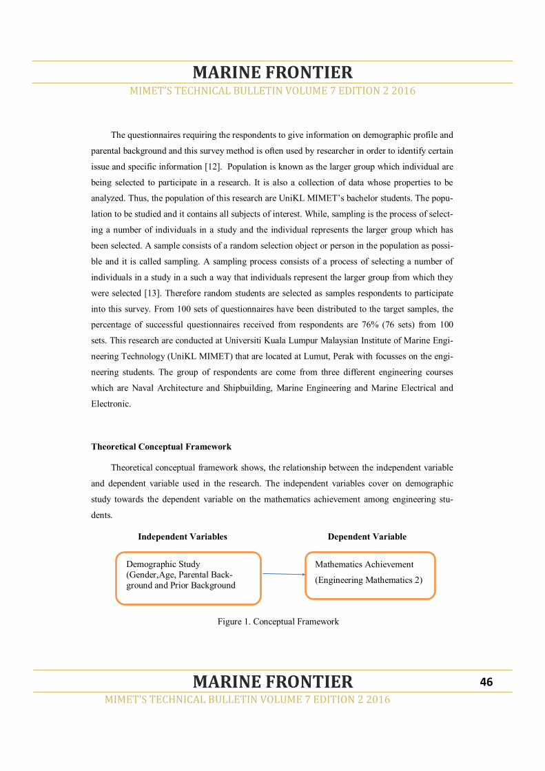
The questionnaires requiring the respondents to give information on demographic profile and
parental background and this survey method is often used by researcher in order to identify certain
issue and specific information [12]. Population is known as the larger group which individual are
being selected to participate in a research. It is also a collection of data whose properties to be
analyzed. Thus, the population of this research are UniKL MIMET’s bachelor students. The popu-
lation to be studied and it contains all subjects of interest. While, sampling is the process of select-
ing a number of individuals in a study and the individual represents the larger group which has
been selected. A sample consists of a random selection object or person in the population as possi-
ble and it is called sampling. A sampling process consists of a process of selecting a number of
individuals in a study in a such a way that individuals represent the larger group from which they
were selected [13]. Therefore random students are selected as samples respondents to participate
into this survey. From 100 sets of questionnaires have been distributed to the target samples, the
percentage of successful questionnaires received from respondents are 76% (76 sets) from 100
sets. This research are conducted at Universiti Kuala Lumpur Malaysian Institute of Marine Engi-
neering Technology (UniKL MIMET) that are located at Lumut, Perak with focusses on the engi-
neering students. The group of respondents are come from three different engineering courses
which are Naval Architecture and Shipbuilding, Marine Engineering and Marine Electrical and
Electronic.
Theoretical Conceptual Framework
Theoretical conceptual framework shows, the relationship between the independent variable
and dependent variable used in the research. The independent variables cover on demographic
study towards the dependent variable on the mathematics achievement among engineering stu-
dents.
Independent Variables Dependent Variable
Figure 1. Conceptual Framework
MIMET’S TECHNICAL BULLETIN VOLUME 7 EDITION 2 2016
MARINE FRONTIER
MIMET’S TECHNICAL BULLETIN VOLUME 7 EDITION 2 2016
MARINE FRONTIER 46
Demographic Study
(Gender,Age, Parental Back-
ground and Prior Background
Mathematics Achievement
(Engineering Mathematics 2)
RESULT AND DISCUSSION
Descriptive Analysis
The demographic characteristics of respondent’s information from two difference groups of
demography as mention before. Table 1 depicted shows the breakdown of the demographic find-
ings. It shows that, 65 percent or 50 respondents have the level of age around 20-23 years and
reasonable expect that circumvented age to pursue undergraduate study. Institutes of higher
learning in Malaysia provide three or four years of education leading to bachelor’s degree pro-
gram. The majority of the respondents are Male students at 89.5 percent or 60 respondents. The
selected respondents are come from the related marine engineering course that involves in the
learning of ship building and ship design. Outwardly, the interest to get involved in the areas that
involving this heavy industries is inclined to male gender. Meanwhile, for parental highest edu-
cation background are divided into two groups, father’s education background and mother’s edu-
cation background.
Malaysian Examination Certification (SPM) level shows the highest percent for parental
education background and indicates that around 40.8 percent and 55.3 percent respectively.
These relation of background are important as measurement tools for student’s achievement in
study that related and influence with their parental education background. More ever, for the
family incomes shows that the highest are in the ranges of RM2,000 to RM5,000. In this ranges
of family incomes, it’s associated with the parental educational background. Parental involve-
ment especially in financial assistance will motivates and gives a positives impact with student’s
achievement. In this research also shows that the number of respondents are highly come from
the group of Bachelor’s Degree in Electrical and Electronic Engineering (BMEE) which are 51.3
percent compare with others two engineering courses, Bachelor’s Degree in Marine Engineering
(BME) and Bachelor’s Degree in Naval Architecture and Shipbuilding. UniKL MIMET was in
collaboration with Department of Sea Malaysia (Jabatan Laut Malaysia) to monitor the only
BME course and requires the students to have through a screening interview and pre-test in or-
der to select an excellent candidates. Finally, majorities of the respondents (84 percent) are en-
rolling engineering course during their previous education and this corresponds and similar to the
engineering courses taken at UniKL MIMET. This finding consistent with the students who took
an engineering courses previously had the opportunity to transfer credit among engineering sub-
jects during their degree level education.
MIMET’S TECHNICAL BULLETIN VOLUME 7 EDITION 2 2016
MARINE FRONTIER
MIMET’S TECHNICAL BULLETIN VOLUME 7 EDITION 2 2016
MARINE FRONTIER 47

Table 1. Descriptive Result on Background Respondents
MIMET’S TECHNICAL BULLETIN VOLUME 7 EDITION 2 2016
MARINE FRONTIER
MIMET’S TECHNICAL BULLETIN VOLUME 7 EDITION 2 2016
MARINE FRONTIER 48
Item Freq % Item Freq %
Age 18-20 11 14.5
Fami-
ly
In-
come
(RM)
below 19 25
20-23
year 50 65.8
2,000 to
5,000 30 39.5
24-28
year 14 18.4
5,000 to
10,000 20 26.3
28 year &
above 1 1.3
more than
10,000 7 9.2
Gender Male 68 89.5 Cours
e BMEE 39 51.3
Female 8 10.5 BME 12 15.8
Father Doctorate 1 1.3 BNASB 25 32.9
Master 3 3.9 Moth
er Doctorate 0 0
Bachelor's
Degree 9 11.8 Master 1 1.3
Diploma 14 18.4 Bachelor's
Degree 8 10.5
Certificate 16 21.1 Diploma 14 18.4
SPM 31 40.8 Certificate 9 11.8
Others 2 2.6 SPM 42 55.3
Prior
Aca-demic
Back-
Engineer-
ing 64 84.2
Others 2 2.6
Science 7 9.2
Art 3 3.9
Others 2 2.6
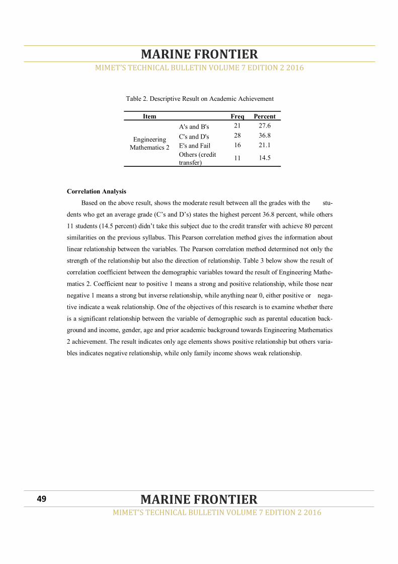
Table 2. Descriptive Result on Academic Achievement
Correlation Analysis
Based on the above result, shows the moderate result between all the grades with the stu-
dents who get an average grade (C’s and D’s) states the highest percent 36.8 percent, while others
11 students (14.5 percent) didn’t take this subject due to the credit transfer with achieve 80 percent
similarities on the previous syllabus. This Pearson correlation method gives the information about
linear relationship between the variables. The Pearson correlation method determined not only the
strength of the relationship but also the direction of relationship. Table 3 below show the result of
correlation coefficient between the demographic variables toward the result of Engineering Mathe-
matics 2. Coefficient near to positive 1 means a strong and positive relationship, while those near
negative 1 means a strong but inverse relationship, while anything near 0, either positive or nega-
tive indicate a weak relationship. One of the objectives of this research is to examine whether there
is a significant relationship between the variable of demographic such as parental education back-
ground and income, gender, age and prior academic background towards Engineering Mathematics
2 achievement. The result indicates only age elements shows positive relationship but others varia-
bles indicates negative relationship, while only family income shows weak relationship.
MIMET’S TECHNICAL BULLETIN VOLUME 7 EDITION 2 2016
MARINE FRONTIER
MIMET’S TECHNICAL BULLETIN VOLUME 7 EDITION 2 2016
MARINE FRONTIER 49
Item Freq Percent
Engineering
Mathematics 2
A's and B's 21 27.6
C's and D's 28 36.8
E's and Fail 16 21.1
Others (credit
transfer) 11 14.5
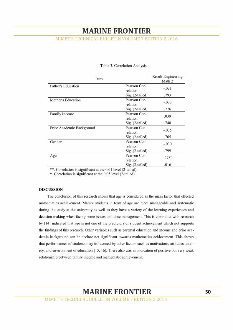
Table 3. Correlation Analysis
DISCUSSION
The conclusion of this research shows that age is considered as the main factor that effected
mathematics achievement. Mature students in term of age are more manageable and systematic
during the study at the university as well as they have a variety of the learning experiences and
decision making when facing some issues and time management. This is contradict with research
by [14] indicated that age is not one of the predictors of student achievement which not supports
the findings of this research. Other variables such as parental education and income and prior aca-
demic background can be declare not significant towards mathematics achievement. This shows
that performances of students may influenced by other factors such as motivations, attitudes, anxi-
ety, and environment of education [15, 16]. There also was an indication of positive but very weak
relationship between family income and mathematic achievement.
MIMET’S TECHNICAL BULLETIN VOLUME 7 EDITION 2 2016
MARINE FRONTIER
MIMET’S TECHNICAL BULLETIN VOLUME 7 EDITION 2 2016
MARINE FRONTIER 50
Item Result Engineering
Math 2
Father's Education Pearson Cor-
relation -.031
Sig. (2-tailed) .793
Mother's Education Pearson Cor-
relation -.033
Sig. (2-tailed) .776
Family Income Pearson Cor-
relation .039
Sig. (2-tailed) .740
Prior Academic Background Pearson Cor-
relation -.035
Sig. (2-tailed) .765
Gender Pearson Cor-
relation -.030
Sig. (2-tailed) .799
Age Pearson Cor-
relation .275*
Sig. (2-tailed) .016
**. Correlation is significant at the 0.01 level (2-tailed). *. Correlation is significant at the 0.05 level (2-tailed).

Therefore, the solution that suggested the changes of lifestyle could help student in reviewing their
achievement in order to improve final performance. Finally, it is important for the students and
university to review other factors with current situation that could increase student result. Proper
communication also important to improve the relationship between the students and lecturer, thus
it also help in creating a strong teamwork in university.
REFERENCES
[1] M. Stolz. The History of Applied Mathematics and the History of Society. (Synthese,133(1-
2), 2002), pp. 43-57.
[2] K. F. Riley, M. P. Hobson & S. J. Bence. Mathematical Methods for Physics and Engineer-
ing: A Comprehensive Guide. (Cambridge University Press, 2006)
[3] S. R. M. Sabri, & F. M. Hamzah. Students’ Perception on Application of Calculus in Civil
Engineering Courses. In PROCEEDINGS OF THE 21ST NATIONAL SYMPOSIUM ON
MATHEMATICAL SCIENCES (SKSM21): Germination of Mathematical Sciences Educa-
tion and Research towards Global Sustainability (Vol. 1605, No. 1, pp. 720-723). (AIP Pub-
lishing, 2014, July).
[4] M. Alves, C.S. Rodrigues, & A.M.A Rocha. Engineering Students and Mathematics Achieve-
ment: A Portuguese Case Study. World Congress on Engineering 2012, WCE 2012.
(Newswood Limited Publisher, 2012)
[5] K. Willcox, & G. Bounova, G. Mathematics in Engineering: Identifying, enhancing and link-
ing the implicit mathematics curriculum. In Proceedings of the 2004 ASEE Annual Confer-
ence & Exposition, Session, no. 2465. (2004).
[6] M. Alves, C.S. Rodrigues, & A.M.A. Rocha. Mathematics Achievement in Engineering: An
Exploratory Study with MIEGI Students. In XVIII International Conference on Industrial
Engineering and Operations Management (ICIEOM 2012). (2012).
[7] M. Jabbar, M.A. Aziz, & S.A. Zeb, Study on Effect of Demographic Factors on the Achieve-
ment of Secondary School Students in the Punjab, Pakistan. International Journal of Academ-
ic Research in Business and Social Sciences 1.(Vol no. 1: 63-76). (2011).
MIMET’S TECHNICAL BULLETIN VOLUME 7 EDITION 2 2016
MARINE FRONTIER
MIMET’S TECHNICAL BULLETIN VOLUME 7 EDITION 2 2016
MARINE FRONTIER 51

[8] P. Roland. Demographic Analysis. (Transaction Publisher, 2009), pp. 1-2.
[9] W. Walton, H. Murnizam, M. Mazni & B. Ferlis. The Effect of Demographic Factors on Aca-
demic Adjustment among Freshman in Malaysia. Quest Journals Journal of Research in Hu-
manities and Social Science (Vol 4, Issue 5, pp: 01-09). (2016).
[10] G. J. Duncan, & K. A. Magnuson, (2005). Can Family Socioeconomic Resources Account
for Racial and Ethnic Test Score Gaps? The Future of Children, 15, 35-54.
[11] A. Usher, & N. Kober, What Roles Do Parent Involvement, Family Background, and Culture
Play in Student Motivation?. Center on education policy. (2012).
[12] A. M. Graziano, & M. L. RaulinResearch is a process of inquiry. Research Methods: A Pro-
cess of Inquiry, 4th Edition. Allyn & Bacon, Needham Heights, MA, 28-53. (2000).
[13] R. Y. Cavana,, B. L. Delahaye, & U. Sekaran. Applied business research: Qualitative and
quantitative methods. John Wiley & Sons Australia. (2001).
[14] J. T. Colorado, & J. Eberle. Student demographics and success in online learning environ-
ments. Emporia State Research Studies, 46(1), 4-10. (2010).
[15] 15. M. Nicolaidou and G. Philippou. Attitudes towards mathematics, self-efficacy and
achievement in problem solving,in European Research in Mathematics Education III, M. A.
Mariotti, Ed., pp. 1–11, University of Pisa, Pisa, Italy. (2003).
[16] S. Maat and E. Zakaria, “The learning environment, teacher’s factor and students attitudes
towards mathematics amongst engineering technology students,” International Journal of Ac-
ademic Research, vol. 2, no. 2, pp. 16–20. (2010).
MIMET’S TECHNICAL BULLETIN VOLUME 7 EDITION 2 2016
MARINE FRONTIER
MIMET’S TECHNICAL BULLETIN VOLUME 7 EDITION 2 2016
MARINE FRONTIER 52

DEVELOPMENT OF NEW CONCEPT OF RUDDER SYSTEM AND FIN CONTROLLER
FOR MINI AUTONOMOUS UNDERWATER VEHICLE (AUV)
NOORAZLINA M. SALIH1, MUHAMAD MOHAMMAD AMIRUDDIN HASHIM2,
NORDIANA JAMIL3, HANISAH JOHOR4
1,2,3Section of Marine Elctrical&Electronics Technology, Malaysian Institute of Marine Engineer-
ing Technology, Universiti Kuala Lumpur, 32200 LUMUT, Perak, Malaysia
4Section of Technical Foundation, Malaysian Institute of Marine Engineering Technology,
Universiti Kuala Lumpur, 32200 LUMUT, Perak, Malaysia
ABSTRACT
An Autonomous Underwater Vehicle (AUV) is considered a vehicle that can submerged underwa-
ter which contains various systems that includes power and controlled by an on-board computer
system, tank systems, rudder controlled systems and maneuvering system. Modular AUV requires
fin and rudder system to maneuver and control the buoyancy of the boat. Fin design as a plate
made from fiber carbon for both sides of the submarines to control the balancing of its body. Fin
and rudder system adjusted the pitch without changing the weight or buoyancy balance. The ve-
hicle is fitted with two fin at forward and aft and two rudder at aft. The new design is contributed
to the invention of mini AUV.
Keywords: autonomous underwater vehicle (AUV), fin system, rudder control, maneuver ,
buoyancy balance, pitch, power.
MIMET’S TECHNICAL BULLETIN VOLUME 7 EDITION 2 2016
MARINE FRONTIER
MIMET’S TECHNICAL BULLETIN VOLUME 7 EDITION 2 2016
MARINE FRONTIER 53
___________________________________________
Corresponding author: [email protected]
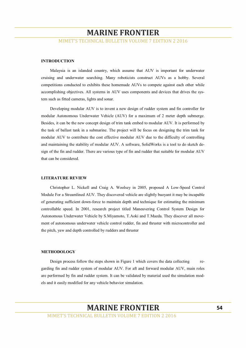
INTRODUCTION
Malaysia is an islanded country, which assume that AUV is important for underwater
cruising and underwater searching. Many roboticists construct AUVs as a hobby. Several
competitions conducted to exhibits these homemade AUVs to compete against each other while
accomplishing objectives. All systems in AUV uses components and devices that drives the sys-
tem such as fitted cameras, lights and sonar.
Developing modular AUV is to invent a new design of rudder system and fin controller for
modular Autonomous Underwater Vehicle (AUV) for a maximum of 2 meter depth submerge.
Besides, it can be the new concept design of trim tank embed to modular AUV. It is performed by
the task of ballast tank in a submarine. The project will be focus on designing the trim tank for
modular AUV to contribute the cost effective modular AUV due to the difficulty of controlling
and maintaining the stability of modular AUV. A software, SolidWorks is a tool to do sketch de-
sign of the fin and rudder. There are various type of fin and rudder that suitable for modular AUV
that can be considered.
LITERATURE REVIEW
Christopher L. Nickell and Craig A. Woolsey in 2005, proposed A Low-Speed Control
Module For a Streamlined AUV. They discovered vehicle are slightly buoyant it may be incapable
of generating sufficient down-force to maintain depth and technique for estimating the minimum
controllable speed. In 2001, research project titled Maneuvering Control System Design for
Autonomous Underwater Vehicle by S.Miyamoto, T.Aoki and T.Maeda. They discover all move-
ment of autonomous underwater vehicle control rudder, fin and thruster with microcontroller and
the pitch, yaw and depth controlled by rudders and thruster
METHODOLOGY
Design process follow the steps shown in Figure 1 which covers the data collecting re-
garding fin and rudder system of modular AUV. For aft and forward modular AUV, main roles
are performed by fin and rudder system. It can be validated by material used the simulation mod-
els and it easily modified for any vehicle behavior simulation.
MIMET’S TECHNICAL BULLETIN VOLUME 7 EDITION 2 2016
MARINE FRONTIER
MIMET’S TECHNICAL BULLETIN VOLUME 7 EDITION 2 2016
MARINE FRONTIER 54

Figure 1. Design process
(a) (b)
Figure 2. The process flow
MIMET’S TECHNICAL BULLETIN VOLUME 7 EDITION 2 2016
MARINE FRONTIER
MIMET’S TECHNICAL BULLETIN VOLUME 7 EDITION 2 2016
MARINE FRONTIER 55

Figure 2 (a) shows the process flow that required fin as input the system. The new concept of fin
system also has decision movement of up and down. For Figure 2(b) shows the flow of rudder as
input the system function. The concept of the rudder system also decision movement if detect
obstacle. The size and the dimension is calculated to complete the design.
RESULT
Figure 3 shows the position of fin plate and rudder, while Figure 4 illustrates the location of the
fin and rudder system in isometric view. Figure 5 illustrates the detail components of fin and rud-
der system which controlled by Arduino coding system. Figure 6 shows the movement of for-
ward fin for both starboard and port.
Figure 3. The position of fin plate and rudder
Figure 4. The location of the fin and rudder system
MIMET’S TECHNICAL BULLETIN VOLUME 7 EDITION 2 2016
MARINE FRONTIER
MIMET’S TECHNICAL BULLETIN VOLUME 7 EDITION 2 2016
MARINE FRONTIER 56
Forward fin
Rudder up
Aft fin
Rudder down
Forward fin(starboard)
Forward fin(port)
Aft fin(starboard)
Aft fin(port)

Figure 5. The detail components of fin and rudder system
Figure 6. The movement of forward fin for both starboard and port.
All figures shown the fin and rudder system to control the balancing of modular AUV. Fin and
rudder system adjust the pitch without changing the weight or buoyancy balance.
MIMET’S TECHNICAL BULLETIN VOLUME 7 EDITION 2 2016
MARINE FRONTIER
MIMET’S TECHNICAL BULLETIN VOLUME 7 EDITION 2 2016
MARINE FRONTIER 57
Rudder up
Aft fin(port)
Aft fin(starboard)
Rudder down
Forward fin(starboard)
Forward fin(port)

CONCLUSION
Autonomous Underwater Vehicle (AUV) is an example of evolution of humanity into better
understanding of the vast sea. Control System for rudder and fin for mini AUV is a vital system
that is required for the degree of movement of the AUV. The project developed to contribute to
the new concept of rudder system and fin controller for mini AUV.
REFERENCES
[1] Nickell, C. L. (2005). Modular modification of a buoyant AUV for low-speed operation.
[2] S.Miyamoto, T.Aoki, T.Maeda, K.Hirokawa, T.Ichikawa, T.Saitou, S.Iwasaki. (2001). Ma-
neuvering Control System Design for Autonomous Underwater Vehicle, Vol. 1, 482–489.
http://doi.org/10.1109/OCEANS.2001.968771
[3] Ming, C., Qiang, Z., & Sanlong, C. (2006). Control System Design of an Autonomous Under-
water Vehicle, 1–6. http://doi.org/10.1109/RAMECH.2006.252736
MIMET’S TECHNICAL BULLETIN VOLUME 7 EDITION 2 2016
MARINE FRONTIER
MIMET’S TECHNICAL BULLETIN VOLUME 7 EDITION 2 2016
MARINE FRONTIER 58

THE NEW CONCEPTUAL DESIGN OF TRIM TANK SYSTEM FOR MINI AUTONO-
MOUS UNDERWATER VEHICLE (AUV)
NOORAZLINA M. SALIH1, MUHAMAD MUZHAFAR ABDULLAH2, NORSHAKILA
ABD RASID3, ATZROULNIZAM ABU4, MOHD SHAHRIZAN MOHD SAID5
1,2,3,4,5Section of Marine Elctrical&Electronics Technology, Malaysian Institute of Marine Engi-
neering Technology, Universiti Kuala Lumpur, 32200 LUMUT, Perak, Malaysia
ABSTRACT
An Autonomous Underwater Vehicle (AUV) is considered a vehicle that can submerged underwa-
ter which contains various systems that includes power and controlled by an on-board computer
system, tank systems, rudder controlled systems and maneuvering system. Submarines use trim or
ballast tanks to control the buoyancy of the boat. Trim tanks are containers that can store air or
water for both sides of the submarines to control the balancing of its body. Trim tank adjust the
pitch without changing the weight or buoyancy balance. The vehicle is fitted with one tank in the
fore and one in the aft. A liquid (water) is moved between the two tanks to shift the weight and
consequently adjusting the pitch. The new design is contributed to the invention of mini AUV.
Keywords: autonomous underwater vehicle (AUV), rudder control, tr im tank, buoyancy
balance, pitch, power.
MIMET’S TECHNICAL BULLETIN VOLUME 7 EDITION 2 2016
MARINE FRONTIER
MIMET’S TECHNICAL BULLETIN VOLUME 7 EDITION 2 2016
MARINE FRONTIER 59
___________________________________________
Corresponding author: [email protected]

INTRODUCTION
Malaysia is an islanded country, which assume that AUV is important for underwater
cruising and underwater searching. Many roboticists construct AUVs as a hobby. Several
competitions conducted to exhibits these homemade AUVs to compete against each other while
accomplishing objectives. All systems in AUV uses components and devices that drives the sys-
tem such as fitted cameras, lights and sonar.
Developing modular AUV is to invent a new design of trim tank for modular Autonomous
Underwater Vehicle (AUV) for a maximum of 2 meter depth submerge. Besides, it can be the new
concept design of trim tank embed to modular AUV. It is performed by the task of ballast tank in
a submarine. The project will be focus on designing the trim tank for modular AUV to contribute
the cost effective modular AUV due to the difficulty of controlling and maintaining the stability of
modular AUV. A software is used to do sketch design of a trim tank system. There are various
type of trim tank that suitable for modular AUV that can be considered.
LITERATURE REVIEW
Jeffery S. Riedel, Anthony J. Healey, David B. Marco and Bahadir Beyazayn in 2014,
proposed a design and development of Low Cost Variable Buoyancy System for the Soft Ground-
ing of Autonomous Underwater Vehicles. They discovered effect of center of gravity and calcula-
tion for center of gravity in low cost variable buoyancy system. On the other hand, Bernhard Gerl
with his research project Development of an autonomous underwater vehicles in an Interdiscipli-
nary context discover most commercial AUV using trimming system by changing the overall den-
sity of AUV. He also discovered that AUV is pitching downwards with the rudder and push down-
wards by propeller and submerging can be forced by sets of propeller.
In 2009, research project titled Modelling for Athwart ships Trim of ship balance and
Actuator with Transferring Liquid among Tanks by Meng Tang, Juan Guo and Wen Shang Nong.
They discover a model of ship balance control for athwart ships trim based on transferring liquid
among tanks is established, by first, a ship dynamics model for athwart ships trim is build based
on the ship static knowledge. In 2011, Li Ji-Qing and Wan Lei with research title The Heel and
Trim Adjustment of Manned Underwater Vehicle Based on Variable Universe Fuzzy S Surface
Control. They discovered manned underwater vehicle has to have good maneuverability, especial-
ly the maneuverability of trim and heel. Moreover ballast water system is a simple and effective
MIMET’S TECHNICAL BULLETIN VOLUME 7 EDITION 2 2016
MARINE FRONTIER
MIMET’S TECHNICAL BULLETIN VOLUME 7 EDITION 2 2016
MARINE FRONTIER 60
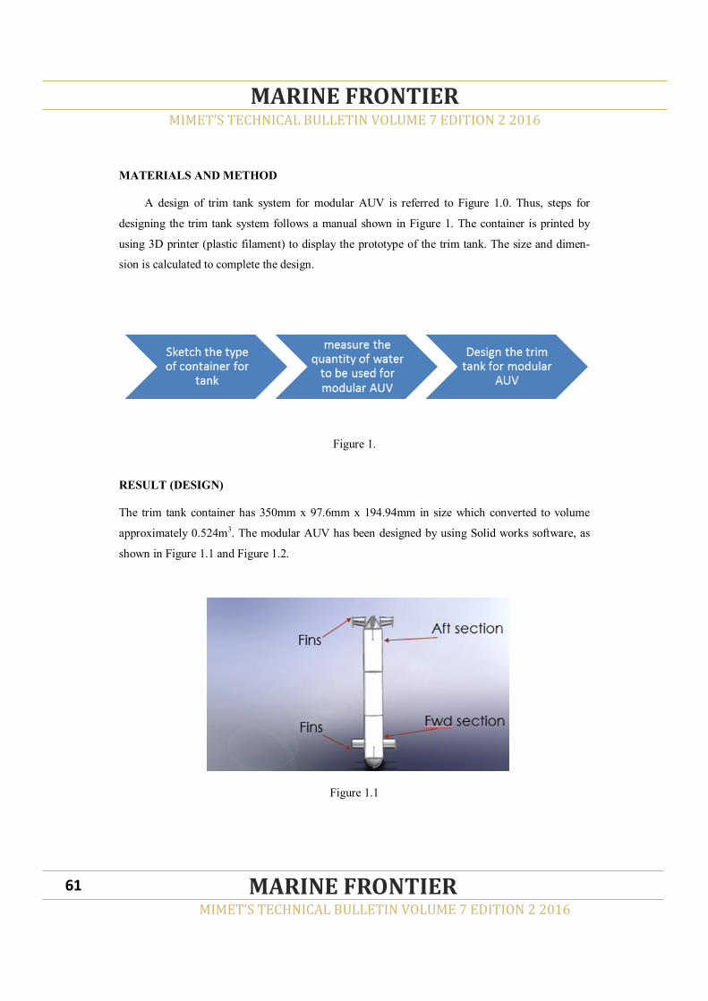
MATERIALS AND METHOD
A design of trim tank system for modular AUV is referred to Figure 1.0. Thus, steps for
designing the trim tank system follows a manual shown in Figure 1. The container is printed by
using 3D printer (plastic filament) to display the prototype of the trim tank. The size and dimen-
sion is calculated to complete the design.
Figure 1.
RESULT (DESIGN)
The trim tank container has 350mm x 97.6mm x 194.94mm in size which converted to volume
approximately 0.524m3. The modular AUV has been designed by using Solid works software, as
shown in Figure 1.1 and Figure 1.2.
Figure 1.1
MIMET’S TECHNICAL BULLETIN VOLUME 7 EDITION 2 2016
MARINE FRONTIER
MIMET’S TECHNICAL BULLETIN VOLUME 7 EDITION 2 2016
MARINE FRONTIER 61

Figure 1.2
The dimension of trim tank has been designed, also detailed in Figure 1.3, Figure 1.4, Figure 1.5
and Figure 1.6
Figure 1.3
MIMET’S TECHNICAL BULLETIN VOLUME 7 EDITION 2 2016
MARINE FRONTIER
MIMET’S TECHNICAL BULLETIN VOLUME 7 EDITION 2 2016
MARINE FRONTIER 62
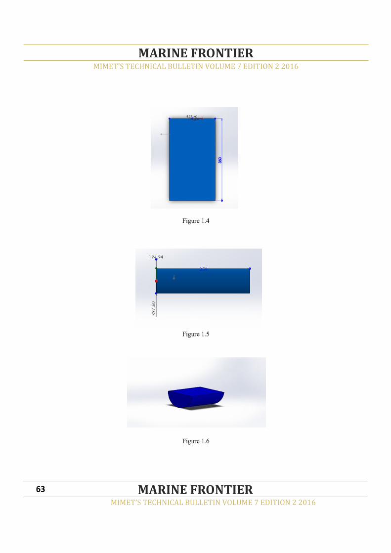
Figure 1.4
Figure 1.5
Figure 1.6
MIMET’S TECHNICAL BULLETIN VOLUME 7 EDITION 2 2016
MARINE FRONTIER
MIMET’S TECHNICAL BULLETIN VOLUME 7 EDITION 2 2016
MARINE FRONTIER 63

Trim tank has been designed in modular AUV, refer to Figure 1.7 and Figure 1.8 below
Figure 1.7
Figure 1.8
MIMET’S TECHNICAL BULLETIN VOLUME 7 EDITION 2 2016
MARINE FRONTIER
MIMET’S TECHNICAL BULLETIN VOLUME 7 EDITION 2 2016
MARINE FRONTIER 64
From all figures discussed earlier, it is shown that the trim tank is important to control the balanc-
ing of modular AUV. Trim tank system adjusted the pitch without changing the weight or buoyan-
cy balance.
CONCLUSION
From the study of this anticipate, the material, size and detail for outlining of trim tank has
been resolved. The new design of trim tank system developed to show the modular AUV can reach
stability by having its buoyancy balance. In order to control the trim tank system, Arduino automa-
tion with coding had been utilized as a part of requirement to finish the undertaking research.
REFERENCES
[1] Listak, M., & Kruusmaa, M. (2003). Buoyancy Control of a Semiautonomous Underwater
Vehicle for Environmental Monitoring in Baltic Sea. Department of Computer Engineering,
Tallin University of Technology (Ehitajate) & Institute of technology, Tartu University
(Vanemuise).
[2] Wang, W. H., Engelaar, R. C., Chen, X. Q., & Chase, J. G. (2009). The state-of-art of under
water vehicles-theories and applications.
[3] Gerl, B. (2006). Development of an Autonomous Underwater Vehicle in an Interdisciplinary
Context. Diploma diss, Dept. of Electrical, Electronic, and Computer Engineering.
[4] Lillemoen, N. F. (2014). Development of Software Tool for Identification of Ballast Errors in
Autonomous Underwater Vehicles.
[5] Masmitja, I., et al. "Development of a control system for an Autonomous Underwater
Vehicle." Autonomous Underwater Vehicles (AUV), 2010 IEEE/OES. IEEE, 2010.
[6] Majeed, Hassaan, et al. "A Cost Efficient Design for an Autonomous Underwater Vehicle
Capable of Localizing and Navigating within a Bounded Body of Water." Computational
Intelligence for Modelling Control & Automation, 2008 International Conference on. IEEE,
2008.
[7] Ji-qing, Li, and Wan Lei. "The heel and trim adjustment of manned underwater vehicle based
on variable universe fuzzy S surface control."Electronics, Communications and Control
(ICECC), 2011 International Conference on. IEEE, 2011.
MIMET’S TECHNICAL BULLETIN VOLUME 7 EDITION 2 2016
MARINE FRONTIER
MIMET’S TECHNICAL BULLETIN VOLUME 7 EDITION 2 2016
MARINE FRONTIER 65

ABSTRACT
An Autonomous Underwater Vehicle (AUV) is considered a vehicle that can submerged underwa-
ter which contains various systems that includes power and controlled by an on-board computer
system, tank systems, rudder controlled systems and manoeuvring system. Submarines use regu-
lating and compensating tank to control the stability of the boat. Regulating and Compensating
Tank are containers that can store air or water for both sides of the submarines to control the bal-
ancing of its body. Regulating and Compensating Tank adjust the pitch without changing the
weight or buoyancy balance. The vehicle is fitted with one tank in the middle and one in the port
and starboard side. A liquid (water) is moved between the three tanks to shift the weight and con-
sequently adjusting the pitch. This project was carried out to propose a new design of regulating
and compensating tanks for modular AUV
Keywords: modular autonomous underwater vehicle (AUV), rudder control, regulating and
compensating tank, buoyancy balance, pitch, power.
MIMET’S TECHNICAL BULLETIN VOLUME 7 EDITION 2 2016
MARINE FRONTIER
MIMET’S TECHNICAL BULLETIN VOLUME 7 EDITION 2 2016
MARINE FRONTIER 66
A DESIGN OF REGULATING AND COMPENSATING TANK SYSTEM FOR MODU-
LAR AUTONOMOUS UNDERWATER VEHICLE (AUV)
NOORAZLINA M. SALIH1, NUR AIMAN ABD HALIM2, NOR AFIZA MOHD NOOR 3,
SITI HAJAR SHAMSUDIN 4
1.2.3.4Universiti Kuala Lumpur, Malaysian Institute of Marine Engineering Technology1
Jalan Pantai Remis, Lumut Perak
__________________________________________
Corresponding author: [email protected]
INTRODUCTION
An autonomous underwater vehicle (AUV) is a robot which travels underwater without requiring
input from an operator. AUVs constitute part of a larger group of undersea systems known as un-
manned underwater vehicles, a classification that includes non-autonomous remotely operated
underwater vehicles (ROVs) controlled and powered from the surface by an operator or pilot via
an umbilical or using remote control. The underwater robots are expected as one of solutions for
underwater activities i.e., maintenance of underwater structures, observations, scientific research,
and investigated the efficiency during recent decades. Especially, the underwater structures are
getting large-scale and large-depth. In order to do safe and efficient works, the works are desired
to be carried out automatically. Until relatively recently, AUVs have been used for a limited num-
ber of tasks dictated by the technology available. AUV also had using by scientists to study lakes,
the ocean and seabed.
In the recent years autonomous underwater vehicles have been attracting a growing amount of
interest due to recent advances in sensor technology. These vehicles are well suited for a variety of
tasks ranging from underwater mineral resource allocation to coral reef monitoring as by. Apart
from applications in open waters, some applications require underwater vehicles to operate within
closed bodies of water such as underwater cave exploration, water tank inspections, dam inspec-
tions, and etc. Furthermore, developing autonomous underwater vehicles is a difficult and expen-
sive task. Therefore, it suffices to investigate designs that are cost effective and easy to implement
for vehicles operating in closed bodies of water. In this paper we propose a complete autonomous
control system, an underwater vehicle, and their integration, such that the integrated vehicle is
capable of operating within bounded bodies of water and is cost efficient and easy to build.
An Autonomous Underwater Vehicle (AUV) is an underwater system that contains its own power
and it’s controlled by on-board computer. The fundamental task for this device is defined: The
vehicle is able to follow a predefined trajectory. The motivation for this paper is to study of regu-
lating tank and compensating tank for modular AUV and capability for a submersible and surfac-
ing vehicle.
MIMET’S TECHNICAL BULLETIN VOLUME 7 EDITION 2 2016
MARINE FRONTIER
MIMET’S TECHNICAL BULLETIN VOLUME 7 EDITION 2 2016
MARINE FRONTIER 67

LITERATURE REVIEW
This chapter describes the mechanical design of regulating and compensating tank for modular
AUV, which include the design of the additional middle part and its materials used. The boundary
lines to the other disciplines are drawn, the necessary space requirements for batteries, circuit-
boards, sensors are known. PAHL&BEITZ (1996) call this phase embodiment design. Embodi-
ment design starts form the working structure or concept of a technical product. The design was
developed, in accordance with technical and economic criteria. Various rules and principles are
proposed for the embodiment design in engineering literature. Pahl & Beitz set up the three basic
rules for embodiment design that are clarity simplicity and safety.
METHODOLOGY
Figure 1 shows a process to produce a design sketch which covers the data collecting regarding
regulating and compensating tank system of modular AUV, parameters to measure the amount of
water required for a tank and a suitable specifications that fit the modular AUVs’ space.
Figure 1. A process to produce a design
MIMET’S TECHNICAL BULLETIN VOLUME 7 EDITION 2 2016
MARINE FRONTIER
MIMET’S TECHNICAL BULLETIN VOLUME 7 EDITION 2 2016
MARINE FRONTIER 68

Figure 2. The process flow
Figure 2 shows the process flow that required tank as input the system. The new concept of regu-
lating and compensating system also has decision movement to stabilize the modular AUV. Pro-
cesses involve the type of valve control system, motor pump and timer to be included in the design
of the tanks.
The system is controlled by Arduino automation which consists of the Uno microcontroller
board based on the ATmega328P. It has 14 digital input/output pins (of which 6 can be used as
PWM outputs), 6 analog inputs, a 16 MHz quartz crystal, a USB connection, a power jack, an
ICSP header and a reset button.
MIMET’S TECHNICAL BULLETIN VOLUME 7 EDITION 2 2016
MARINE FRONTIER
MIMET’S TECHNICAL BULLETIN VOLUME 7 EDITION 2 2016
MARINE FRONTIER 69

RESULT
Figure 3.
Figure 4.
The dimension of regulating tank has been designed, refer to Figure 5,6 and 7
MIMET’S TECHNICAL BULLETIN VOLUME 7 EDITION 2 2016
MARINE FRONTIER
MIMET’S TECHNICAL BULLETIN VOLUME 7 EDITION 2 2016
MARINE FRONTIER 70
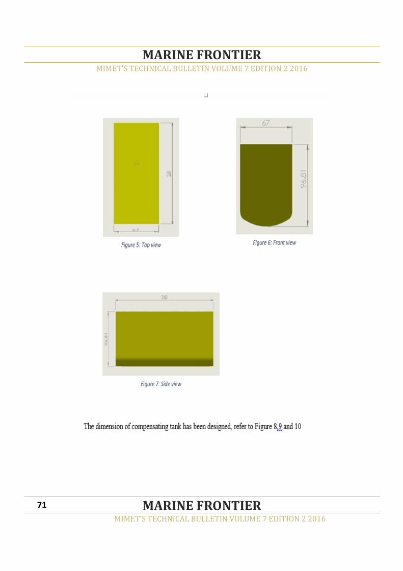
MIMET’S TECHNICAL BULLETIN VOLUME 7 EDITION 2 2016
MARINE FRONTIER
MIMET’S TECHNICAL BULLETIN VOLUME 7 EDITION 2 2016
MARINE FRONTIER 71
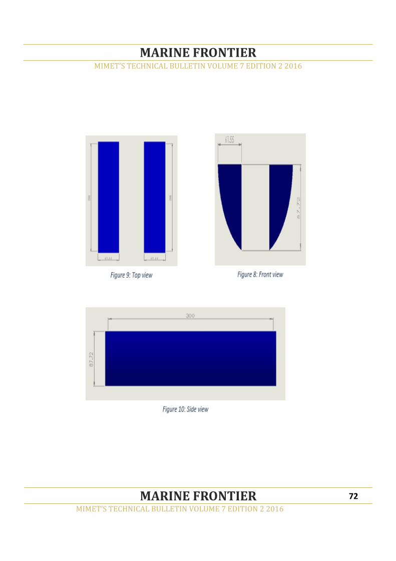
MIMET’S TECHNICAL BULLETIN VOLUME 7 EDITION 2 2016
MARINE FRONTIER
MIMET’S TECHNICAL BULLETIN VOLUME 7 EDITION 2 2016
MARINE FRONTIER 72

CONCLUSION
Autonomous Underwater Vehicle (AUV) is an example of evolution of humanity into better un-
derstanding of the vast sea. Control System for rudder and fin for mini AUV is a vital system that
is required for the 6-degree of movement of the AUV. The project created a system with advance
system coding capable of containing important information for the movement even with the up-
grades of external hardware’s. From the research of this project, the material, size and specifica-
tion for designing regulating tank and compensating tank has been determined. For control system
of the regulating tank and compensating tank, several hardware and software had been used in
order to complete the project that focusing the best design to be chosen.
REFERENCES
[1] Gerl, B. (2006). Development of an Autonomous Underwater Vehicle in an Interdisciplinary
Context. Diploma diss, Dept. of Electrical, Electronic, and Computer Engineering.
[2] Wakita, N., Hirokawa, K., Ichikawa, T., & Yamauchi, Y. (2010). Development of Autono-
mous Underwater Vehicle (AUV) for Exploring Deep Sea Marine Mineral Re-
sources. Mitsubishi Heavy Industries Technical Review, 47(3), 73.
[3] Vervoot. (2008). Modelling and Control of Unmanned Underwater Vehicle.
Lind, E., & Meijer, M. (2014). Simulation and Control of Submarines.
[4] Aktiengesellschaft, G. L. (june 2008). Rules for Classification and Construction III Naval
Ship Technology. Rules or Classification and Construction III Naval Ship Technology.
MIMET’S TECHNICAL BULLETIN VOLUME 7 EDITION 2 2016
MARINE FRONTIER
MIMET’S TECHNICAL BULLETIN VOLUME 7 EDITION 2 2016
MARINE FRONTIER 73
ABSTRACT
This paper describes the desigining of integrated fluid parametric workbench for varity of
experiments. Fluid parametric analysis is to identify potential fluid and to see other applications
that can be practiced in the industry. This involved in fluid physical analysis such as fluid density,
the volume and weight of the fluid. The experiments will varify the theorical of fluid law and the
application in the real practice, that requires tools or workbench. The design concept refers to a
variety of parametric analyzer and to combine them into an integrated workbench. This require the
research literature, analysis of design, material selection and employment components. The
estimated project cost is RM20K (Ringgit Malaysia: Twenty thousand only) and fully funded by
the Universiti Kuala Lumpur Malaysian Institute of Marine Engineering and Technology (UniKL-
MIMET). This design will be considered as a potential research project to be developed as well as
further research on the fluid medium in the future. Hopefully it would be useful and provide
knowledge to researchers.
Keywords: Integrated work bench, fluid parametric, static fluid, fluid flow, fluid force
MIMET’S TECHNICAL BULLETIN VOLUME 7 EDITION 2 2016
MARINE FRONTIER
MIMET’S TECHNICAL BULLETIN VOLUME 7 EDITION 2 2016
MARINE FRONTIER 74
DESIGN OF INTEGRATED FLUID PARAMETRIC ANALYSIS WORKBENCH
M.A ISHAK1, MD SALIM KAMIL2, MAZLAN MUSLIM3
1,2,3 Universiti Kuala Lumpur Malaysian Institute of Marine Engineering Technology, Dataran Industri Teknologi Kejuruteraan Marin, Bandar Teknologi Maritim, Jalan Pantai Remis, 32200
Lumut, Perak, Malaysia.
[email protected], [email protected], [email protected]
___________________________________________
Corresponding author: [email protected]

INTRODUCTION
Fluid analysis is critical at identifing characteristic of fluid where the data will be used as
information to design the several functions in machine operations. The parametric of fluid should
be analyzed so that the limitation or capability of the fluid is known specifically. The nature some
of parametric with the practical knowledge is advantage to understanding for other applications.
The important parameters are pressure, density, temperature, viscosity, compressibility, etc [1].
These parameters are considered as fluid properties and are required to be studied to identify the
ability of fluid performance in engineering application. In most of the experiments in fluid
laboratory, hydraulic bench will be used to determine the flow rate of water through various sets
of apparatus. The purpose of the present experiment is to gain some familiarity with the use of a
hydraulic bench to study several fluid parameters. The fluid laboratory is required to conduct tests
on fluid properties, fluid parametric, and fluid flow [1].
On-site tests can be conducted to estimate the quantity of pipe and channel flows. It is used
for Fluid Mechanics study. Special instruments are needed for the study Basic Hydraulic Benches,
Water Jet Apparatus, Flow Meter & Current Meter, Ventury Meter Apparatus, Pipe Friction
Apparatus, Loose fixtures and shapes in Piping (Bends) Apparatus, Flow through An Orifice & Jet
Apparatus, Centrifugal Pumps, Rainfall Measuring Equipments and Run-Off Measuring Devices.
The laboratory with specialized equipment are required for the analysis, collection and display of
descriptive and coordinate information. Through lab work, students can learn theoretical aspects
of fluid engineering environment. A good lab should be equipped with Digital Theodalites, Total
Stations, Automatic Levels, Surveyor’s Compass, Digital Planimeters, and Computer Hardware &
Software for plotting and printing survey plans. The preparation of the equipment will incur high
cost as an example, the hydraulic properties workbench produced by GUNT Hamburg cost
RM95,000.00 (ringgit Malaysia; ninety five thousand) net per unit [2]. This cost is quiet expensive
even though the fluid parameter can be tested in a basic parameter of flow rate measuring for
various pipe diameter. The economic value is unreasonable. In this study, several parameter tests
are integrated into one workbench and it’s to be more cost effective.
MIMET’S TECHNICAL BULLETIN VOLUME 7 EDITION 2 2016
MARINE FRONTIER
MIMET’S TECHNICAL BULLETIN VOLUME 7 EDITION 2 2016
MARINE FRONTIER 75

METHODOLOGY
The methodology used in the project will be reviewed such as to measures include a project work
on the theoretical study of the existing workbench and then followed by a sketch in accordance
with the requirements of the selected experiments. Next, engineering calculations to determine the
validity of the workbench and view the capabilities and choice of materials can be made. Some
items included as structure strength, the ability of control experiments were also analyzed Work-
bench. The method in these fluid parametric analysis were use the Design of Experiments (DOE)
method, where the various analysis method will be define from the existing method and the meth-
od design will be setting base on the simple practice, broad of experience and produce an accuracy
results. The various experimental will be design according to the parameter to be analyzed such as
the experiment to determine the volume flow rate and mass flow rate, is different in parameter
however the workbench will be share with minimum adjustment is required.
Then, the experiment test bench is design after the experiment method has selected, where the
bench will consist of components and fittings for various parameter identification such as pipe
diameter for volume and mass flow, pipe length for flow friction and continuity flow, various fit-
ting type for flow regime, friction factor and losses in pipe. The experiment will be carried out on
the bench and the data produced is required to be verified whether these data are accurate. There-
fore, the reference data is required for the experiment and the prior study on that particular param-
eter is need. The reference need in these verify experimental such as components materials and
fittings method, pipeline route, and various data for fluid parametric. In the final result of the
study, the analysis fluid parametric will be to customize the experimental workbench and method,
respectively. The customizing of these is to ensure that the standard of methodological is correct
and the experiment workbench is valid for the fluid parametric analysis in future.
MIMET’S TECHNICAL BULLETIN VOLUME 7 EDITION 2 2016
MARINE FRONTIER
MIMET’S TECHNICAL BULLETIN VOLUME 7 EDITION 2 2016
MARINE FRONTIER 76

RESULT AND DISCUSSION
In this chapter, results and discussion will be made on the study design the integrated Fluid Analy-
sis Workbench. This discussion will touch on matters such as design calculations, material selec-
tion in design, selection and layout components. The design calculations included of the estima-
tion of the tank volume and weight, the total volume of fluid in the pipeline system and its weight,
water pump capacity, the amount of friction in the pipeline and the amount of head loss, and count
on the workbench structure strength. The selection of materials refers to the ability of corrosion,
the strength of the pressure in the system, material that is easy to run and in the current market
price. Layout selection is also dependent on the type of experiment to be carried out the concept of
integration in experimental and operator comfort Workbench.
DESIGN CALCULATIONS
Design calculation is needed in designing the project as required so that it is safe to use and
can be operated according to specification requirements. The calculations involved are to calculate
water volumes in the system for determine the water tank capacity, the estimations weight of the
components in the system for calculate the structure reliability, water pump capacity, pressure in
pipe line, fluid force due to water impacts, and structure analysis. Some components will go
through this process as follows:
MIMET’S TECHNICAL BULLETIN VOLUME 7 EDITION 2 2016
MARINE FRONTIER
MIMET’S TECHNICAL BULLETIN VOLUME 7 EDITION 2 2016
MARINE FRONTIER 77

WATER TANK CAPACITY
Water tanks are used to store water used as medium in the workbench. There are two types of
tank specifically bottom tank and top tank. Bottom tank is used as a collector and supplier of the
medium, refer to Figure 4.1. Top tank is used as a system tank, where the medium being dis-
charged into it and will be used by the system during the operations, refer to Figure 4.2. The de-
sign calculations performed on the tank design includes the total volume of water collected and
the volume of water used in the system. Tank size is designed based on several factors which need
the volume of water in the system, collecting the water in the system during a shutdown, reducing
the storing space and cost of construction of the tank. The water level set 0.05m from the top of
the tank is to act as buffer spacing in the event of failure, such as level indicator system failed to
shows the actual level of water in the tank, pump switch breakdown and so forth.
3.1.1.1 Specifications of Bottom Tank
Length; L = 750mm (0.75m)
Width; W = 500mm (0.50m)
High; H = 250mm (0.25m)
Water Level, h = 200mm (0.20m)
Bottom Tanks Volumetric;
VBT= L X W X h
= 0.75 X 0.50 X 0.20 = 0.075m³
Water Density, ρ as at 30ºC = 996 kg/m³ (refer Appendix 1: Water Properties)
Water mass in tank (kg); WwBT = VBT X ρ
= 0.075 X 996 = 74.70 kg
Tank mass without load; Wtl = 30 kg (mass measured by the estimation on the materials density-
fibreglass)
Total mass of water tank, ∑WT1 = WwBT + Wtl
= 74.70 + 30
MIMET’S TECHNICAL BULLETIN VOLUME 7 EDITION 2 2016
MARINE FRONTIER
MIMET’S TECHNICAL BULLETIN VOLUME 7 EDITION 2 2016
MARINE FRONTIER 78

Specifications of Top Tank
Length; L = 500mm (0.5m)
Width; W = 300mm (0.3m)
High; H = 350mm (0.35m)
Water Level, h = 300mm (0.3m)
Top Tanks Volumetric; VTT= L X W X h
= 0.5 X 0.3 X 0.3 = 0.045m³
Water Density, ρ as at 30ºC = 996 kg/m³ (refer Appendix 1: Water Properties)
Water mass in tank (kg); WwTT = VTT X ρ = 0.045 X 996 = 44.82 kg
Tank mass without load; Wt2 = 25 kg (mass measured by the estimation on the materials density-
fibreglass)
Total mass of water tank, ∑WT = WwTT + Wt2 = 44.82 + 25 = 69.82 kg
PIPELINE CAPACITY
Pipeline is used for draining medium that can be done on the experimental medium in accord-
ance with the prescribed procedure. The selection of the size of the pipe design is made based on
the needs of the experiment to be conducted such as Fluid Static experiments, Fluid Flow experi-
ments and Fluid Force experiments. Apart from the experimental factors, the selection of pipe size
and material refers to the limited space and reducing construction costs, respectively. The design
calculation is performed on the pipeline is to calculate the volume of water is contained and the
total weight of each pipe. The pipeline design is divided into four groups of Supply Pipeline, Pipe-
line Delivery, and Pipeline Return System. The pipeline sketch is shown and the specification is
discussed in this section.
MIMET’S TECHNICAL BULLETIN VOLUME 7 EDITION 2 2016
MARINE FRONTIER
MIMET’S TECHNICAL BULLETIN VOLUME 7 EDITION 2 2016
MARINE FRONTIER 79
Water
Level
0.5
0.3
0.3
0.35
Figure 4.2. Top Tank

MIMET’S TECHNICAL BULLETIN VOLUME 7 EDITION 2 2016
MARINE FRONTIER
MIMET’S TECHNICAL BULLETIN VOLUME 7 EDITION 2 2016
MARINE FRONTIER 80
Specifications of Supply Line
Supply Pipeline installed to connect the supply to the medium of Bottom Tank Top Tank. Fig-
ure 4.3 shows a sketch of the supply pipeline and selected materials are PVC material. The pipe
size selection is made on several factors, the water should be channeled into the Tank Top, Tank
Top position 2.5m above the water pump and it refers to the Fluid Static experimental require-
ments.
Specifications of Delivery Line
Delivery Line is a pipeline system that connects Tank Top with Pipeline System. Figure 4.4 illus-
trate the delivery line, where it was divided into two connections of Delivery Line 1 is connected
to the side Top Tank, while the Delivery Line 2 is connected at the bottom of the Tank Top and the
materials selected are PVC material. The size selection of the pipe design is made based on the
needs of the experiment to be conducted Fluid Static tests.

Specifications of System Line
Pipeline system is connected to the Delivery Line, so that experiments can be performed on
the medium. Some equipment such as valves, check valves, pressure gauge, flow meter, piezom-
eter and jet apparatus has been installed. This installation is in accordance with the manufacturer
specification. Figure 4.5 shows the Pipeline System, which is divided into two connections that
are System Line 1 connected to the Delivery Line 1 and System Line 2 connected to the Deliv-
ery Line 2. Two connections are used to test the medium at two different experiments. System
Line 1 used in the experiments Fluid Flow, where the numbers of connections and equipment
have been made, such as globe valves, elbows, straight connectors, tee-connector, reducer-
enlarge connector, flow meters, pressure gauges and manometers-tap ports. System Line 2 used
in the Fluid Force experiments, where the pipeline will be connected directly to the Impact Jet
Apparatus.
MIMET’S TECHNICAL BULLETIN VOLUME 7 EDITION 2 2016
MARINE FRONTIER
MIMET’S TECHNICAL BULLETIN VOLUME 7 EDITION 2 2016
MARINE FRONTIER 81

Specifications of Overflow Line
The Over-flow pipeline is connected between the Top Tank and the Bottom Tank and the sche-
matics of pipeline is as Figure 4.7. The pipeline diameter designed as dia.32mm due to require-
ment of avoiding any obstacle on over flow water into bottom tank.
Design Calculation for Pipeline
MIMET’S TECHNICAL BULLETIN VOLUME 7 EDITION 2 2016
MARINE FRONTIER
MIMET’S TECHNICAL BULLETIN VOLUME 7 EDITION 2 2016
MARINE FRONTIER 82

Pipe inside diameter, di = 20mm (0.020m)
Water volumetric in Pipeline; Vp = A X ∑Ln = (π X D²)/4 X ∑Ln
From table 4.1, the ∑Ln is 13.95m, thus; = (π X 0.020²) / 4 X 13.95 = 4.382E-03 m³
Water mass in pipeline; Wpl = ρ X Vp = 996 X 4.382E-03 = 4.36 kg
Empty pipeline mass, Wep = 5.50 kg
Total pipeline mass, ∑Wp = Wpl + Wep = 4.36 + 5.50 = 9.86 kg
WATER PUMP CALCULATION
Water flow rate, Q = 25 l/min (0.417 l/s @ 4.17E-4 m³/s) – estimate the quantity requirements
by the system due to pump in and return line flow rate. Pressure supply, P1 = 0.25Mpa (2.5bar.g)
– estimate from the static pressure for the top tank high from datum is 2.5m. So that from the
formula; pump power describe as the equations show are; Pump power, Pf = m g HPL (Watt) [1].
Where;
m – mass flow rate (kg/s)
g – gravity (9.81 m/s²)
HPL – pump head (m) or total head loss in pipe due to pipe fittings/connections
and fluid flow.
Head Loss due to pipe fitting, HPL = (f L/d + ∑K) v²/2g
Where; f – friction factor due to fluid flow in pipe, use Moody Graph
L – pipe length (m)
d – pipe diameter (m)
∑K – Total K factor due to fitting/connection
v – Average velocity in pipe (m/s)
MIMET’S TECHNICAL BULLETIN VOLUME 7 EDITION 2 2016
MARINE FRONTIER
MIMET’S TECHNICAL BULLETIN VOLUME 7 EDITION 2 2016
MARINE FRONTIER 83

To determine friction factor, f by using Moody Graph.
Step 1; Calculate flow regime by define Reynolds number Re = vdρ / μ, where v – fluid velocity
(m/s) in pipe, d – pipe diameter (m), ρ – fluid density at temperature (kg/m³) and μ – dynamics
viscosity (Pas).
Re = 0.955 X 0.02 X 996 / 0.80E-3
= 23,779.5 @ 2.4E4 (turbulent flow)
Step 2; Define Relative Roughness, μR = μ / d, where μ - absolute roughness (mm) and d – pipe
diameter (mm), refer to Appendix 2.
μR = 0.00015 / 20 = 0.0000075
Step 3; Plot the Re and μR in Moody Graph and define the friction factor, f by intersect line meet.
Result from chart, f = 0.022
To determine total K factor due to pipe fitting/connection, ∑K. Refer to table K Factors for
common fittings.
Step 1: Identify the fittings / connections type
Step 2: Proved the table with fitting particulars and K factor for every fittings / connections by
referring to Figure 4.8: Pipe fitting and connection for System Line 1.
MIMET’S TECHNICAL BULLETIN VOLUME 7 EDITION 2 2016
MARINE FRONTIER
MIMET’S TECHNICAL BULLETIN VOLUME 7 EDITION 2 2016
MARINE FRONTIER 84
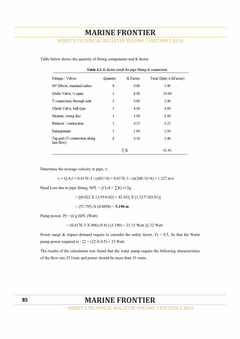
Table below shows the quantity of fitting components and K factor.
Determine the average velocity in pipe, v;
v = Q/A1 = 0.417E-3 / (πD1²/4) = 0.417E-3 / (π(20E-3)²/4) = 1.327 m/s
Head Loss due to pipe fitting, HPL = (f L/d + ∑K) v²/2g
= [(0.022 X 13.95/0.02) + 42.45)] X [1.327²/2(9.81)]
= (57.795) X (0.0898) = 5.190 m
Pump power, Pf = m’g HPL (Watt)
= (0.417E-3 X 996) (9.81) (5.190) = 21.15 Watt @ 22 Watt
Power surge & impact demand require to consider the safety factor, Fs = 0.5, So that the Water
pump power required is ; 22 + (22 X 0.5) = 33 Watt.
The results of the calculation was found that the water pump require the following characteristics
of the flow rate 25 l/min and power should be more than 35 watts.
MIMET’S TECHNICAL BULLETIN VOLUME 7 EDITION 2 2016
MARINE FRONTIER
MIMET’S TECHNICAL BULLETIN VOLUME 7 EDITION 2 2016
MARINE FRONTIER 85
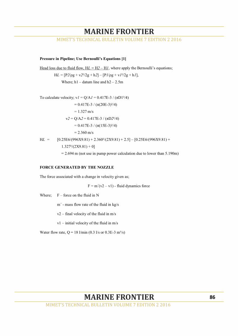
Pressure in Pipeline; Use Bernoulli’s Equations [1]
Head loss due to fluid flow, HL = H2 – H1, where apply the Bernoulli’s equations;
HL = [P2/ρg + v2²/2g + h2] – [P1/ρg + v1²/2g + h1],
Where; h1 – datum line and h2 – 2.5m
To calculate velocity; v1 = Q/A1 = 0.417E-3 / (πD1²/4)
= 0.417E-3 / (π(20E-3)²/4)
= 1.327 m/s
v2 = Q/A2 = 0.417E-3 / (πD2²/4)
= 0.417E-3 / (π(15E-3)²/4)
= 2.360 m/s
HL = [0.25E6/(996X9.81) + 2.360²/(2X9.81) + 2.5] – [0.25E6/(996X9.81) +
1.327²/(2X9.81) + 0]
= 2.694 m (not use in pump power calculation due to lower than 5.190m)
FORCE GENERATED BY THE NOZZLE
The force associated with a change in velocity given as;
F = m´(v2 – v1) - fluid dynamics force
Where; F – force on the fluid in N
m´ - mass flow rate of the fluid in kg/s
v2 – final velocity of the fluid in m/s
v1 – initial velocity of the fluid in m/s
Water flow rate, Q = 18 l/min (0.3 l/s or 0.3E-3 m³/s)
MIMET’S TECHNICAL BULLETIN VOLUME 7 EDITION 2 2016
MARINE FRONTIER
MIMET’S TECHNICAL BULLETIN VOLUME 7 EDITION 2 2016
MARINE FRONTIER 86
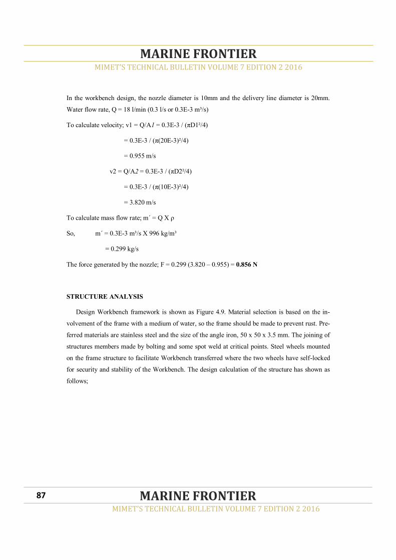
MIMET’S TECHNICAL BULLETIN VOLUME 7 EDITION 2 2016
MARINE FRONTIER
MIMET’S TECHNICAL BULLETIN VOLUME 7 EDITION 2 2016
MARINE FRONTIER 87
In the workbench design, the nozzle diameter is 10mm and the delivery line diameter is 20mm.
Water flow rate, Q = 18 l/min (0.3 l/s or 0.3E-3 m³/s)
To calculate velocity; v1 = Q/A1 = 0.3E-3 / (πD1²/4)
= 0.3E-3 / (π(20E-3)²/4)
= 0.955 m/s
v2 = Q/A2 = 0.3E-3 / (πD2²/4)
= 0.3E-3 / (π(10E-3)²/4)
= 3.820 m/s
To calculate mass flow rate; m´ = Q X ρ
So, m´ = 0.3E-3 m³/s X 996 kg/m³
= 0.299 kg/s
The force generated by the nozzle; F = 0.299 (3.820 – 0.955) = 0.856 N
STRUCTURE ANALYSIS
Design Workbench framework is shown as Figure 4.9. Material selection is based on the in-
volvement of the frame with a medium of water, so the frame should be made to prevent rust. Pre-
ferred materials are stainless steel and the size of the angle iron, 50 x 50 x 3.5 mm. The joining of
structures members made by bolting and some spot weld at critical points. Steel wheels mounted
on the frame structure to facilitate Workbench transferred where the two wheels have self-locked
for security and stability of the Workbench. The design calculation of the structure has shown as
follows;

Structure Mass
The frame cross-sections area, A(m²) is shows in Figure 4.8. The area calculation is important
to determine the strength magnitude in the framework structure. The magnitude will be used to
define the capability of structure in loading the experiment components and apparatus. The cross
sections area calculations as below;
A = (0.050 X 0.0035) + (0.0465 X 0.0035)
= 1.75E-4 + 1.6275E-4
= 3.3775E-4 m²
Ln – frame length (m) identification by referring to Figure 4.9.
Frame mass; FWn = ρ X (A X ∑Ln) = 8450 X (3.3775E-4 X 37.10)
= 105.88 kg @ 106 kg
MIMET’S TECHNICAL BULLETIN VOLUME 7 EDITION 2 2016
MARINE FRONTIER
MIMET’S TECHNICAL BULLETIN VOLUME 7 EDITION 2 2016
MARINE FRONTIER 88
Figure 4.8. Cross Section Stainless
Steel Angle Bar
0.05
0.0035
0.0465
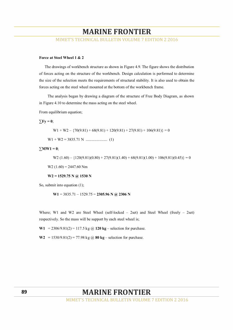
Force at Steel Wheel 1 & 2
The drawings of workbench structure as shown in Figure 4.9. The figure shows the distribution
of forces acting on the structure of the workbench. Design calculation is performed to determine
the size of the selection meets the requirements of structural stability. It is also used to obtain the
forces acting on the steel wheel mounted at the bottom of the workbench frame.
The analysis began by drawing a diagram of the structure of Free Body Diagram, as shown
in Figure 4.10 to determine the mass acting on the steel wheel.
From equilibrium equation;
∑Fy = 0;
W1 + W2 – {70(9.81) + 68(9.81) + 120(9.81) + 27(9.81) + 106(9.81)} = 0
W1 + W2 = 3835.71 N ...................... (1)
∑MW1 = 0;
W2 (1.60) – {120(9.81)(0.80) + 27(9.81)(1.40) + 68(9.81)(1.00) + 106(9.81)(0.45)} = 0
W2 (1.60) = 2447.60 Nm
W2 = 1529.75 N @ 1530 N
So, submit into equation (1);
W1 = 3835.71 – 1529.75 = 2305.96 N @ 2306 N
Where; W1 and W2 are Steel Wheel (self-locked – 2set) and Steel Wheel (freely – 2set)
respectively. So the mass will be support by each steel wheel is;
W1 = 2306/9.81(2) = 117.5 kg @ 120 kg – selection for purchase.
W2 = 1530/9.81(2) = 77.98 kg @ 80 kg – selection for purchase.
MIMET’S TECHNICAL BULLETIN VOLUME 7 EDITION 2 2016
MARINE FRONTIER
MIMET’S TECHNICAL BULLETIN VOLUME 7 EDITION 2 2016
MARINE FRONTIER 89

Figure 4.9. Structure of Workbench Frame
MIMET’S TECHNICAL BULLETIN VOLUME 7 EDITION 2 2016
MARINE FRONTIER
MIMET’S TECHNICAL BULLETIN VOLUME 7 EDITION 2 2016
MARINE FRONTIER 90

WORKBENCH DESIGN - PRELIMINARY
Based on the performed calculations, a design concept of the workbench was produced as
shown in Figure 4.11. Workbench Illustration.
SUMMARY
In the summary, the discussion on the final design drawings and circuit diagrams, the expected
performance, the estimated construction costs, and potential for commercialization. This will pro-
vide an overview of the success of the project design and raised the Workbench development pro-
posals as it deems necessary for the future.
MIMET’S TECHNICAL BULLETIN VOLUME 7 EDITION 2 2016
MARINE FRONTIER
MIMET’S TECHNICAL BULLETIN VOLUME 7 EDITION 2 2016
MARINE FRONTIER 91

ENGINEERING DRAWING
The restructuring of the pipeline is made after taking into account several factors, namely the
composition of the installation of pipeline and pipeline junction to avoid and reduce unnecessary
connections. In addition, the measurement of the workbench dimensional structure and the addi-
tion of equipment for experiments have been made to adjust the workbench to be more reliable.
The result of the restructuring of the concept design has been successfully performed. In addition,
the circuit diagram of the workbench is also adjusted to enable the operator to understand the op-
eration of the workbench. Circuit diagram is shown in Figure 4.12 where the number of symbols
used to indicate the equipment is installed in the workbench. Through this circuit diagram, the
operator can make the arrangement of the experiment and determine the type of experiment to be
conducted. This will facilitates the user to understand the actual operation of workbench and the
correct order to avoid mistakes choosing experimental equipment.
MIMET’S TECHNICAL BULLETIN VOLUME 7 EDITION 2 2016
MARINE FRONTIER
MIMET’S TECHNICAL BULLETIN VOLUME 7 EDITION 2 2016
MARINE FRONTIER 92
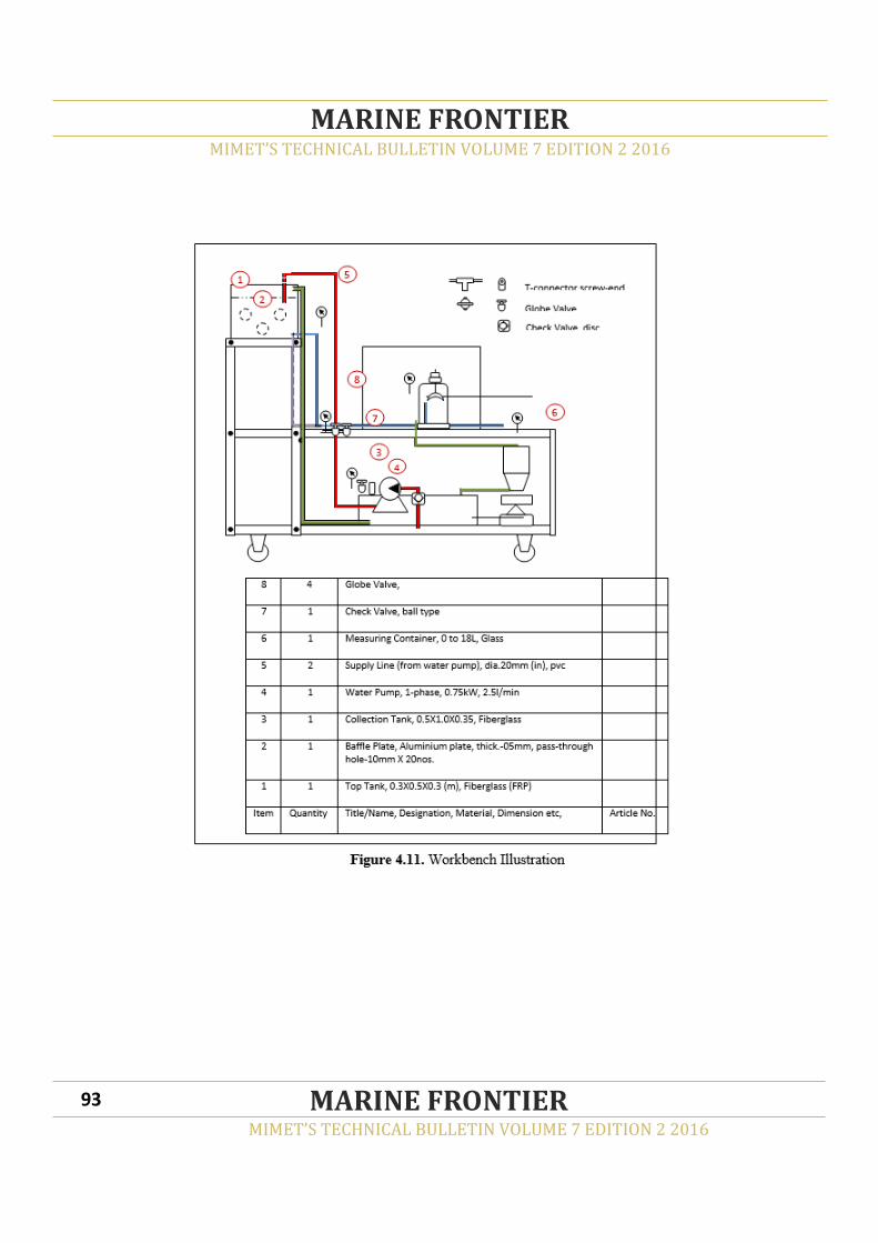
MIMET’S TECHNICAL BULLETIN VOLUME 7 EDITION 2 2016
MARINE FRONTIER
MIMET’S TECHNICAL BULLETIN VOLUME 7 EDITION 2 2016
MARINE FRONTIER 93
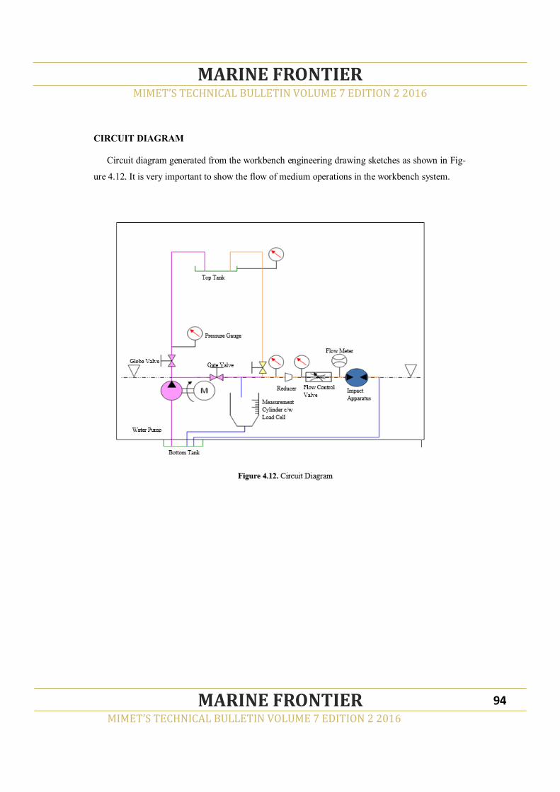
CIRCUIT DIAGRAM
Circuit diagram generated from the workbench engineering drawing sketches as shown in Fig-
ure 4.12. It is very important to show the flow of medium operations in the workbench system.
MIMET’S TECHNICAL BULLETIN VOLUME 7 EDITION 2 2016
MARINE FRONTIER
MIMET’S TECHNICAL BULLETIN VOLUME 7 EDITION 2 2016
MARINE FRONTIER 94

MIMET’S TECHNICAL BULLETIN VOLUME 7 EDITION 2 2016
MARINE FRONTIER
MIMET’S TECHNICAL BULLETIN VOLUME 7 EDITION 2 2016
MARINE FRONTIER
EXPECTED PERFORMANCE
The workbench is expected designed to handle experiments on Static Fluid, Fluid Flow and
Fluid Force. The Fluid Static study start when the water is pumped up to the Top Tank until full.
Then the water is drained to the bottom pipeline by gravity through a pipeline system is construct-
ed, according to specification of the test. The information to be obtained is the total pressure at the
outlet of the Top Tank and at the end of the pipeline at 2.4 meters below from the Top Tank. This
pressure information can be used to understand the theory of Fluid Static parameters.
Studies on Fluid Flow begins when the water is circulating in the pipe system and through
some connections such as Elbows 90°, Tee Connector, Reducer and Enlargement connector and
some equipment such as Strainer, Globe Valve, Manometer Port-tap, Pressure Gauge and Flow
Meter. Water flow will be collected in a measuring container. Information such as total pressure,
flow volume and the time available will be used to understand the theory of fluid flow in pipes.
Fluid Force experiment requires the use of Impact Jet Apparatus (IJA). Water is pumped into
the piping system and distributed to IJA, where the total power generated is measured by the
weight attached. These weights represent the amount of power generated from the water jet to push
the IJA Cone. The information obtained will help in understanding the strength of the pressurized
fluid to produce mechanical power such as used in hydro electric power generator.
EXPECTED COST
In this topic, discussed the structure of the workbench products are specified by sub-
components and the total estimated construction cost.
PRODUCT STRUCTURE
Based on the structure of workbench frame, as shown in Figure 4.9 and preliminary design of
workbench as shown in Figure 4.11, the preparation and fractional part refers to the level of prod-
uct structure can be made. This is important in scheduling the project as an assessment of the cost
of ordering the equipment, stocking and installation.
95

MIMET’S TECHNICAL BULLETIN VOLUME 7 EDITION 2 2016
MARINE FRONTIER
MIMET’S TECHNICAL BULLETIN VOLUME 7 EDITION 2 2016
MARINE FRONTIER
BILL OF MATERIALS (BOM)
According to the explanation of the product structure, then the list of components and equip-
ment can be made as shown in Table 4.4: Components and Apparatus List. This information is
required for calculating the actual cost of purchase of components and equipment, so that no ex-
cess or deficiency occur when the installation work and construction commences. In addition, it is
also used for acquisition scheduling and project management.
96

MIMET’S TECHNICAL BULLETIN VOLUME 7 EDITION 2 2016
MARINE FRONTIER
MIMET’S TECHNICAL BULLETIN VOLUME 7 EDITION 2 2016
MARINE FRONTIER
Through the list, quotation of the purchase to be made in accordance with the correct specifica-
tion and can be seen in the cost of components and equipment purchases as shown in Table 4.5.
The construction and installation costs are listed in Table 4.6. These cost estimates only for the
purpose of obtaining the estimated total cost of Workbench to compare with the current market
price for such workbench can be made. This is one of the objectives of the project design was im-
plemented.
97

MIMET’S TECHNICAL BULLETIN VOLUME 7 EDITION 2 2016
MARINE FRONTIER
MIMET’S TECHNICAL BULLETIN VOLUME 7 EDITION 2 2016
MARINE FRONTIER
The total of workbench construction cost is estimated at RM 20,000.00 (Ringgit Malaysia;
Twenty thousand only). The design calculations involved are water tanks and pipeline capacity,
water pump selection, and structure analysis. Based on the design of the workbench project
objectives have been achieved and it has been shown in Table 5.1.
98
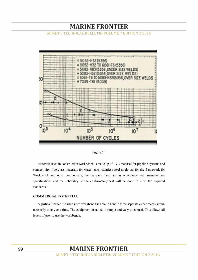
MIMET’S TECHNICAL BULLETIN VOLUME 7 EDITION 2 2016
MARINE FRONTIER
MIMET’S TECHNICAL BULLETIN VOLUME 7 EDITION 2 2016
MARINE FRONTIER
Figure 5.1
Materials used in construction workbench is made up of PVC material for pipeline systems and
connectivity, fiberglass materials for water tanks, stainless steel angle bar for the framework for
Workbench and other components, the materials used are in accordance with manufacturer
specifications and the reliability of the confirmatory test will be done to meet the required
standards.
COMMERCIAL POTENTIAL
Significant benefit to user since workbench is able to handle three separate experiments simul-
taneously at any one time. The equipment installed is simple and easy to control. This allows all
levels of user to use the workbench.
99

MIMET’S TECHNICAL BULLETIN VOLUME 7 EDITION 2 2016
MARINE FRONTIER
MIMET’S TECHNICAL BULLETIN VOLUME 7 EDITION 2 2016
MARINE FRONTIER
CONCLUSION
The experiment on the fluid is a current need in the field of mechanical engineering. The most
often carried out experiments on fluid properties, fluid flow in the pipeline and impact force of the
fluid. All three tests and experimental procedure are different, but using the same basic equipment
such as water tanks, valves, pressure gauges, pipeline system, and measuring cylinder. Therefore,
the construction of experimental workbench that combines these three experiments to increase the
use of basic equipment usage and cost. Other savings are obtained as experimental equipment
purchase cost savings, reduction of spacing, time saving on equipment preparation and expedite
the collection of information on the experimental results that there was no repetition of the same
procedure for each experiment.
The workbench design which consist the basic of fluid analysis experiments as stated in this
project objective had been successfully achieved. The integrated of fluid experiment into one
workbench had been designed and the number of apparatus of experimental unit had been reduced,
so these will be affected in reducing the equipment cost. The project had been provided the
engineering drawing and fabrication drawing for the individual pipeline system and also provided
the circuit diagram of the designed workbench.
If research continues to improve, this will increase the value added to the experimental device
and will also attract researchers to learn more about engineering fluid. It is hoped that ongoing
efforts will produce researchers who can produce a better experiment tools, including the use of
software and the visual in future.
100
MIMET’S TECHNICAL BULLETIN VOLUME 7 EDITION 2 2016
MARINE FRONTIER
MIMET’S TECHNICAL BULLETIN VOLUME 7 EDITION 2 2016
MARINE FRONTIER
REFERENCES
[1] Roger Kinsky 1996. Thermodynamics & Fluid Mechanics –Introduction. Basic Properties of
Fluids, page: 179 – 282. McGraw-Hill Book Company Australia Pty Limited, 4 Barcoo
Street, Roseville NSW 2069, Australia.
[2] GUNT Hamburg, 1984. Fluid Mechanics and Hydrology - Fundamentals of Fluid Mechanics.
http://www.gunt.de/static/s12_1.php?p1=&p2=&pN=. Accessed on 12th February 2010.
[3] McGraw-Hill Professional, April 2007 – Scientific and Technical Terms. http://
www.answers.com/topic/globe-valve. Accessed on 10th February 2010
Landis, Scott (1987). The Workbench Book, page: 211-220. Taunton Press.
[4] Pipeline Engineering & Supply Co. Ltd, North Yorkshire, DL10 7JQ,United Kingdom, 2006 –
Pipeline Engineering. http://www.pipelineengineering.com. Accessed on 10th February 2010.
[5] DOE, August 31, 2005 - Hydrogen Pipeline. Working Group Workshop.
www1.eere.energy.gov/hydrogenandfuelcells. Accessed on 5th March 2010.
[6] Needham, Joseph (1986). Science and Civilization in China: Volume 4, Part 2. Taipei: Caves
Books Ltd. Page 33.
[7] McGraw-Hill Professional (2006) – Architecture diagram shows disc- globe valve with bolted
bonnet. http://www.answers.com/topic/globe-valve. Accessed on 15th March 2010.
[8] CORTEC Manfiold Systems Production and Drilling Equipment, 2006 Globe Valve Disks http://www.tpub.com/content/doe/h1018v2/css/h1018v2_37.htm. Accessed on 21st March
2010.
[9] THERM EXCEL - Properties of Fluids - Physical characteristics of water; http://
www.thermexcel.com/english/tables/eau_atm.htm. Accessed on 9th October 2010.
[10] THE ENGINEERING TOOL BOX – Roughness and Surface Coefficient of Ventilations
Duct; http://www.engineeringtoolbox.com/surface-roughness-ventilation-ducts-d_209.html.
Accessed on 9th October 2010.
101

MIMET’S TECHNICAL BULLETIN VOLUME 7 EDITION 2 2016
MARINE FRONTIER
MIMET’S TECHNICAL BULLETIN VOLUME 7 EDITION 2 2016
MARINE FRONTIER
[11] Wikipedia, the free encyclopaedia – Viscosity; http://en.wikipedia.org/wiki/Viscosity.
Accessed on 17th March 2010.
[12] Wikipedia, the free encyclopaedia – Friction; http://en.wikipedia.org/wiki/Friction. Accessed
on 17th March 2010.
[13] Meriam, J. L.; L. G. Kraige (2002). Engineering Mechanics (fifth ed.). John Wiley & Sons. Page: 328.
[14] Wikipedia, the free encyclopaedia – Pipeline Transport; http://en.wikipedia.org/wiki/
Pipeline_transport. Accessed on 17th March 2010.
102

MIMET’S TECHNICAL BULLETIN VOLUME 7 EDITION 2 2016
MARINE FRONTIER
MIMET’S TECHNICAL BULLETIN VOLUME 7 EDITION 2 2016
MARINE FRONTIER
ABSTRACT
Strain gauge and Data Logger is an optional device to determine strength of a vessel such as Small
Waterplane Area Twin Hull (SWATH). A SWATH ship is a high-speed craft which is commonly
used in naval as patrol or passenger craft. In this research, a non-conventional method of measur-
ing the fluid dynamics and fatigue strength of SWATH model is proposed. It involved methods of
elaborating the readings at Strain gauge measurement displayed on Data Logger monitor.
103
DETERMINATION AND FATIGUE STRENGTH OF ALUMUNIUM SWATH MODEL IN
COMPLIANCE WITH CLASSIFICATION RULES
MAZLAN MUSLIM1, MD SALIM KAMIL2, M A ISHAK3
1,2,3Universiti Kuala Lumpur, Malaysian Institute of Marine Engineering Technology, Jalan Pantai
Remis, 32200 Lumut, Perak
[email protected], [email protected], [email protected]
___________________________________________
Corresponding author: [email protected]

MIMET’S TECHNICAL BULLETIN VOLUME 7 EDITION 2 2016
MARINE FRONTIER
MIMET’S TECHNICAL BULLETIN VOLUME 7 EDITION 2 2016
MARINE FRONTIER
INTRODUCTION
SWATH (small waterplane area twin hull) ships have been proved to have much lower motion
than monohull ships in any mode of oscillation. This lower motion is obtained from the combina-
tion of deeply submerged hulls and the small waterplane area of the struts. The deeply submerged
hulls. which provide the buoyancy will experience low wave exciting forces whereas the small
waterplane area of a SWATH ensures the natural frequency will be much lower than an equivalent
conventional vessel.
The paper focuses on research of Small Waterplane Area Twin Hull (SWATH) in order to
improve the ship condition such as become faster, withstand high load, low fuel consumption and
adequate strength. The model of Aluminium had been constructed and this report is based on de-
termination of fatigue strength by using a device called Strain Gauge and Data Logger.
104
MIMET’S TECHNICAL BULLETIN VOLUME 7 EDITION 2 2016
MARINE FRONTIER
MIMET’S TECHNICAL BULLETIN VOLUME 7 EDITION 2 2016
MARINE FRONTIER
Behavior of catamarans in marine passenger transport at rough weather and sea conditions is
quite unacceptable. Too large stability scope and small resistance elements are calling into ques-
tion not only the health of passengers and crew affected but it also leads to the risk for drawback
of travelling by sea.
Mentioned disadvantages can be reduced by the adjustment of hull spacing, as shown before,
but not entirely. Alternatively, the problem can be approached from a different view: If there is an
issue in too stable catamaran vessel, which at the external forces reacts too quick, same forces
have to be utterly reduced.
More precisely, the seakeeping ability of the vessel is strictly determined by the shape and size
of the waterplane. Reducing the same, external forces don't even have an opportunity to affect
vessel's surface, at least not entirely. In that way the most effective design of the catamaran repre-
sent SWATH (Small Waterplane Area Twin Hull) catamaran.
OBJECTIVES
The objectives of the paper are as follows:
I. To conduct testing on the SWATH 2.3m model by using Strain Gauge and Data Log-
ger.
II. To identify and conduct analysis of fatigue strength of SWATH 2.3m model.
III. To compare the calculation result with the Classification Rules of structural analysis.
METHODOLOGY
Applying the Strain Gauge on the SWATH model, measurement of strain can be achieved by us-
ing the Data Logger. The points are below the strut of the SWATH at forward starboard, forward
port, after starboard and after port.
105

MIMET’S TECHNICAL BULLETIN VOLUME 7 EDITION 2 2016
MARINE FRONTIER
MIMET’S TECHNICAL BULLETIN VOLUME 7 EDITION 2 2016
MARINE FRONTIER
Figure 2. Strain Gauge Points on the model testing
Figure 3. Completed Strain Gauge attachment
106

MIMET’S TECHNICAL BULLETIN VOLUME 6 EDITION 2 2015
MARINE FRONTIER
MIMET’S TECHNICAL BULLETIN VOLUME 7 EDITION 2 2016
MARINE FRONTIER
By measuring the change in resistance we can measure the strain. To gain the result of the
strain test, Data Logger and computer are required to measure the strain. The strain reading will be
sent to the Data Logger and transcribe it into the computer. The condition of the measurement can
be controlled by the computer. The particulars that can be controlled are speed of measurement,
accuracy, elimination of transcription errors, automate testing and repetition.
Results and Discussion
The test consist of applying loads on the deck of the SWATH which comprise of 1.25kg of weight
for each readings. The figure 4 below shows the S-N curve of aluminium welded joint.
Figure 4. S-N Curve of Aluminium Welded Joint
107

MIMET’S TECHNICAL BULLETIN VOLUME 7 EDITION 2 2016
MARINE FRONTIER
MIMET’S TECHNICAL BULLETIN VOLUME 7 EDITION 2 2016
MARINE FRONTIER
CONCLUSION
Strain Gauge and Data Logger method of measuring strength of SWATH model has been devel-
oped successfully, several experimental measurement were successfully conducted. The testing
proves that the usage of Strain Gauge and Data Logger is able to measure the strength of the mod-
el and by this result, researchers will assisted for the future SWATH design.
To have more efficient experiment, it is suggest that to conduct the experiment in proper envi-
ronment such as towing tank. The experiment can be consist to carry out hydrodynamic tests with
the SWATH model, for the purpose of designing a new model, or refining the design of a ship
to improve the ship’s performance at sea.
Outcome of this study will be useful for the ship construction industry and marine engi-
neering in particular. This technique is also useful for other engineering fields such as structural
and also laboratory work because it can help to reduce time on data generation and data pro-
cessing.
108

MIMET’S TECHNICAL BULLETIN VOLUME 7 EDITION 2 2016
MARINE FRONTIER
MIMET’S TECHNICAL BULLETIN VOLUME 7 EDITION 2 2016
MARINE FRONTIER
REFERENCES
[1] Adi Maimun Abd Malik, Shaharudin Ahmad and Amir Radzi Ab Ghani, 2013, Structure
Strength of Semi- Swath: Real Time Measurement.
[2] Weiqin Liu,Weiguo Wu, Shuangxi Xu, Xiaobin Li, 2011, Study on Longitudinal Ulti-
mate Strength Analysis Method for High Speed Trimaran,
[3] R.C.Hibbeler, 2008, Mechanics of Materials, Pearson
[4] Yasuhisa Okumoto, Yu Takeda, Masaki Mano, Tetsuo Okada, 2009, Design of Ship Hull
Structures, Springer
[5] V. Dubrovsky, A. Lyakhovitsky, 2001, Multi-hull Ships, Backbone Publishing Company
[6] The Royal Institution of Naval Architects, 1985, International Conference on SWATH Ships
and Advanced Multi-hull Vessels, The Royal Institution of Naval Architects.
109

MIMET’S TECHNICAL BULLETIN VOLUME 5 EDITION 1 2014
MARINE FRONTIER
MIMET’S TECHNICAL BULLETIN VOLUME 7 EDITION 2 2016
MARINE FRONTIER
CALL FOR PAPERS To inculcate the research culture amongst academics, Universiti Kuala Lumpur Malaysian Institute of Marine Engineering Technology (UniKL MIMET) is publishing the Marine Frontier@UniKL Research Bulletin. For a start, the bulletin will be published two times a year, in March and September. Original research papers, which have not been published or cur-rently being considered for publication elsewhere, will be considered. Accepted Types of Research The papers accepted for the bulletins must be based on any of the following types of research:
Basic research (pure basic research and strategic basic research)
Applied research
Experimental development
Critical review Pure basic research is experimental and theoretical work undertaken to acquire new knowledge without looking for long -terms benefits other than advancement of knowledge. Strategic basic research is experimental and theoretical work undertaken to acquire new knowledge directed into speci-fied broad areas in the expectation of useful discoveries. It provides the broad base of knowledge necessary for the solu-tion of recognised practical problems. Applied research is original work undertaken primarily to acquire new knowledge with a specific application in view. It is undertaken either to determine possible use for the findings of basic research or to determine new ways of achieving some specific and predetermined objectives. Experimental development is systematic work, using existing knowledge gained from research or practical experience that is directed to producing new materials, products or devices, to installing new processes, systems and services, or to improving substantially those already produced or installed. Critical review is a comprehensive preview and critical analysis of existing literature. It must also propose a unique lens, framework or model that helps understand specific body of knowledge or address specific research issues. Condition of Acceptance The editorial board considers all papers on the condition that:
They are original
The authors hold the property or copyright of the paper
They have not been published already
They are not under consideration for publication elsewhere, nor in press elsewhere
They use non-discriminatory language
The use of proper English (except for manuscripts written in Bahasa Melayu-applicable for selective only) All papers must be typed on A4 size page using Microsoft Words. The complete paper must be approximately 3,500 words long (excluding references and appendixes). The format is described in detail in the next section. All papers are reviewed by the editorial board and evaluated according to:
Originality
Significance in contributing new knowledge
Technical adequacy
Appropriateness for the bulletin
Clarity of presentation All papers will be directed to the appropriate team and/or track. The papers will be reviewed by reviewer(s) and/or edi-tor. All review comments and suggestions should be addressed in the final submission if the paper is accepted for publica-tion, copyright is transferred to the bulletin. Please submit your paper directly to the Chief Editor – [email protected] or the Executive Editor– [email protected] for publication in the next issue of the Marine Frontier@UniKL.
110