Slide 5.4- 1 Copyright © 2007 Pearson Education, Inc. Publishing as Pearson Addison-Wesley.
Upload
griffin-benedict-foxCategory
view
218download
0
1© 2007 Pearson Education, Inc. Publishing as Pearson Addison-Wesley
Architectural Architectural Modeling NotationsModeling Notations
2© 2007 Pearson Education, Inc. Publishing as Pearson Addison-Wesley
ObjectivesObjectives
To present several notations for architectural modeling
• Box-and-line diagrams• UML package diagrams• UML component diagrams• UML deployment diagrams
To present UML common notations• Notes• Constraints• Properties• Stereotypes
3© 2007 Pearson Education, Inc. Publishing as Pearson Addison-Wesley
TopicsTopics
Box-and-line diagrams UML common notations Packages and package diagrams Components and component
diagrams Nodes, artifacts, and deployment
diagrams
4© 2007 Pearson Education, Inc. Publishing as Pearson Addison-Wesley
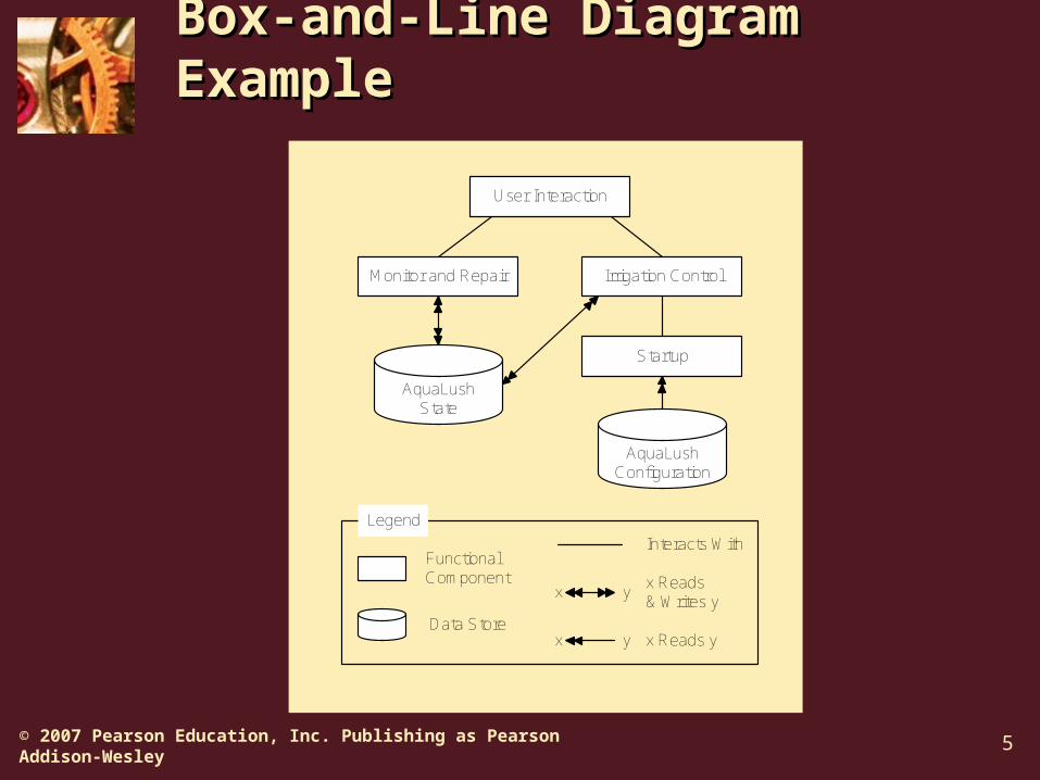
Box-and-Line DiagramsBox-and-Line Diagrams
Icons (boxes) connected with lines No rules governing formation Used for both static and dynamic
modeling Good idea to include a legend
5© 2007 Pearson Education, Inc. Publishing as Pearson Addison-Wesley
Box-and-Line Diagram Box-and-Line Diagram ExampleExample
Functional Component
Legend
Interacts With
AquaLush State
Data Store
AquaLush Configuration
User Interaction
Irrigation ControlMonitor and Repair
Startup
x Reads & Writes y
x Reads y
x
x
y
y

6© 2007 Pearson Education, Inc. Publishing as Pearson Addison-Wesley
Box-and-Line Diagram Box-and-Line Diagram HeuristicsHeuristics
Make box-and-line diagrams only when no standard notation is adequate.
Keep the boxes and lines simple. Make symbols for different things look
different. Use symbols consistently in different
diagrams. Use grammatical conventions to name
elements. Don’t mix static and dynamic elements.

7© 2007 Pearson Education, Inc. Publishing as Pearson Addison-Wesley
UML Notes and UML Notes and ConstraintsConstraints
Note—A dog-eared box connected to model elements by a dashed line
• May contain arbitrary text• Used for comments and specifications
Constraint—A statement that must be true of entities designated by model elements
• Written inside curly brackets• Beside single model elements• Beside a dashed line connecting several
model elements

8© 2007 Pearson Education, Inc. Publishing as Pearson Addison-Wesley
UML Properties and UML Properties and StereotypesStereotypes
Property—Characteristic of an entity designated by a model element
• List of tagged values in curly brackets• Tagged value: tag = value• Boolean properties that are true may drop
the value and equals sign Stereotype—A model element given
more specific meaning• Shown with icons, colors, graphics• Stereotype keywords between guillemots,
for example «interface»
9© 2007 Pearson Education, Inc. Publishing as Pearson Addison-Wesley
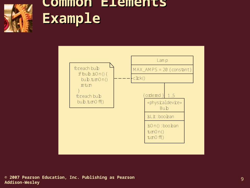
Common Elements Common Elements ExampleExample
1..5
for each bulb if !bulb.isOn() { bulb.turnOn() return }for each bulb
bulb.turnOff()
Bulb
isLit : boolean
isOn() : booleanturnOn()turnOff()
Lamp
MAX_AMPS = 20 { constant }
click()
«physical device»
{ ordered }

10© 2007 Pearson Education, Inc. Publishing as Pearson Addison-Wesley
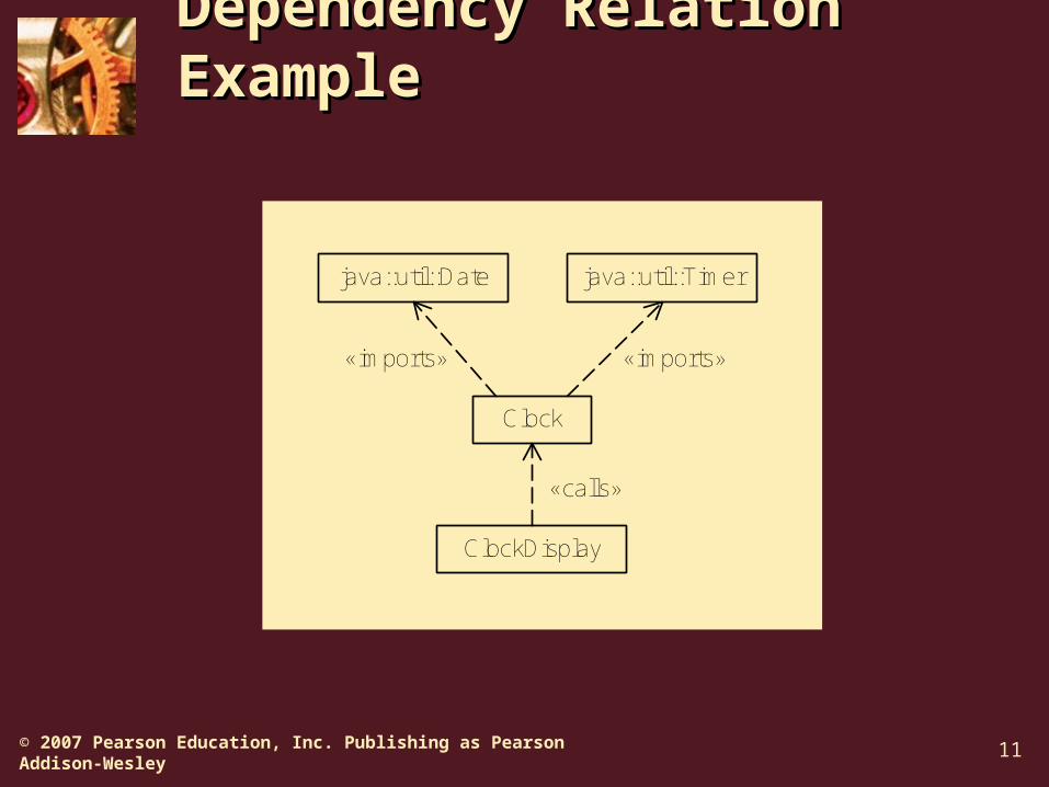
UML Dependency UML Dependency RelationsRelations
Examples: D uses I, D depends for compilation on I, D imports I
Represented by dependency arrows: stereotyped dashed arrows
A dependency relation holds between two entities D and I when a
change in I (the independent entity) may affect D (the dependent entity).
A dependency relation holds between two entities D and I when a
change in I (the independent entity) may affect D (the dependent entity).
11© 2007 Pearson Education, Inc. Publishing as Pearson Addison-Wesley
Dependency Relation Dependency Relation ExampleExample
java::util::Date java::util::Timer
Clock
ClockDisplay
«imports»
«calls»
«imports»
12© 2007 Pearson Education, Inc. Publishing as Pearson Addison-Wesley
UML PackagesUML Packages
A UML package is a collection of model elements, called package members.
The package symbol is a file folder• Package name in tab if body is
occupied, otherwise in the body• Members shown in body or using a
containment symbol (circled plus sign)• Often connected by import or export
dependency arrows
13© 2007 Pearson Education, Inc. Publishing as Pearson Addison-Wesley
Package DiagramsPackage Diagrams
A UML package diagram is one whose primary symbols are package symbols.
Useful for• Static models of modules, their parts,
and their relationships• Architectural modeling

14© 2007 Pearson Education, Inc. Publishing as Pearson Addison-Wesley
Package Diagram Package Diagram ExampleExample
Switches
ToggleSwitch
Three-WaySwitch
DimmerSwitch
Wiring
Two-Wire
Three-Wire
Four-Wire
Electrical Parts
15© 2007 Pearson Education, Inc. Publishing as Pearson Addison-Wesley
Software ComponentsSoftware Components
A software component is a reusable, replaceable piece of software.
Component-based development is an approach in which products are designed and built using commercially available or custom-built software components.

16© 2007 Pearson Education, Inc. Publishing as Pearson Addison-Wesley
UML Component UML Component DiagramsDiagrams
A UML component is a modular, replaceable unit with well-defined interfaces.
• Component symbols are rectangles containing names
• Stereotyped «component» or have component symbol in upper right-hand corner
A UML component diagram shows components, their relationships to their environment, and their internal structure.

17© 2007 Pearson Education, Inc. Publishing as Pearson Addison-Wesley
UML InterfacesUML Interfaces
A UML interface is a named collection of public attributes and abstract operations.
• Represented by a stereotyped class symbol (later)
• Represented by special ball and socket symbols
Note: this use of the term “interface” is different from out previous use as a communications boundary.

18© 2007 Pearson Education, Inc. Publishing as Pearson Addison-Wesley
Provided and Required Provided and Required InterfacesInterfaces
A class or component realizes an interface when it includes its attributes and implements its operations.
Provided interface—Realized by a class or component
• Represented by a ball or lollipop symbol Required interface—Needed by a class
or component• Represented by a socket symbol
The assembly connector wires interfaces together.

19© 2007 Pearson Education, Inc. Publishing as Pearson Addison-Wesley
Interface Symbols Interface Symbols ExampleExample
«component»ImageRenderer
«component»CompressionEngine
Compression Compression BitString
«component»ImageRenderer
«component»CompressionEngine
Compression
BitString

20© 2007 Pearson Education, Inc. Publishing as Pearson Addison-Wesley
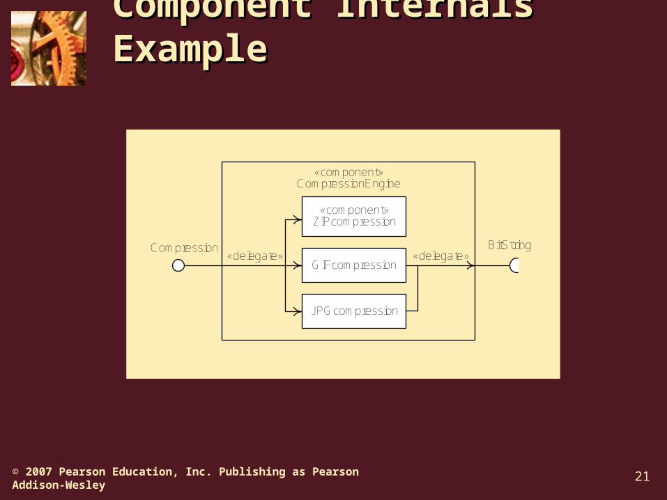
Component Internal Component Internal StructureStructure
Components can contain other components or classes showing how they are built.
A delegation connector ties a component interface to one or more internal classes or components that realize or use the interface.
• Solid arrows• Stereotyped with «delegate»
21© 2007 Pearson Education, Inc. Publishing as Pearson Addison-Wesley
Component Internals Component Internals ExampleExample
«component»CompressionEngine
Compression BitString
«component»ZIPcompression
GIFcompression
JPGcompression
«delegate» «delegate»

22© 2007 Pearson Education, Inc. Publishing as Pearson Addison-Wesley
Component Diagram Component Diagram UsesUses
Static models of software components (reusable and replaceable parts)
Model program components• Architectural models• Detailed design models• Relationship to environment
Model internal structure of components
23© 2007 Pearson Education, Inc. Publishing as Pearson Addison-Wesley
Logical and Physical Logical and Physical ArchitectureArchitecture
Logical architecture—The configuration of a product’s major parts and their relationships in abstraction from implementation as code on a real machine
Physical architecture—The realization of a product as code and data files residing and executing on computational resources
UML deployment diagrams model physical architecture.

24© 2007 Pearson Education, Inc. Publishing as Pearson Addison-Wesley
UML ArtifactsUML Artifacts
A UML artifact is any physical representation of data used or produced during development or operation.
• Examples: Files, documents, program code Artifacts have types and instances
• Represented by rectangles containing names• Stereotyped «artifact» or have artifact symbol in
upper right-hand corner• Instances have underlined names, types do
not Artifacts realize logical entities (classes,
components, etc.)
25© 2007 Pearson Education, Inc. Publishing as Pearson Addison-Wesley
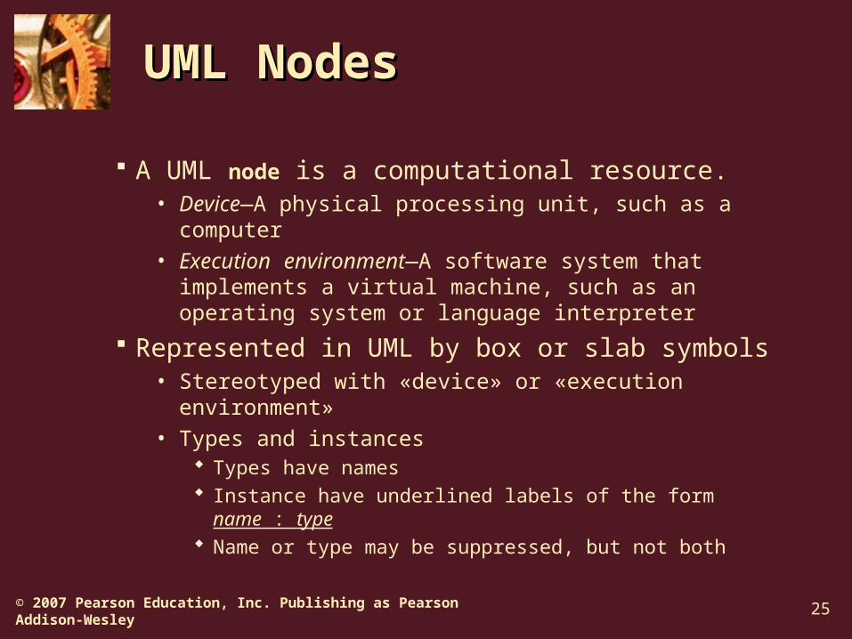
UML NodesUML Nodes
A UML node is a computational resource.• Device—A physical processing unit, such as a
computer• Execution environment—A software system that
implements a virtual machine, such as an operating system or language interpreter
Represented in UML by box or slab symbols• Stereotyped with «device» or «execution environment»• Types and instances
Types have names Instance have underlined labels of the form name :
type Name or type may be suppressed, but not both
26© 2007 Pearson Education, Inc. Publishing as Pearson Addison-Wesley
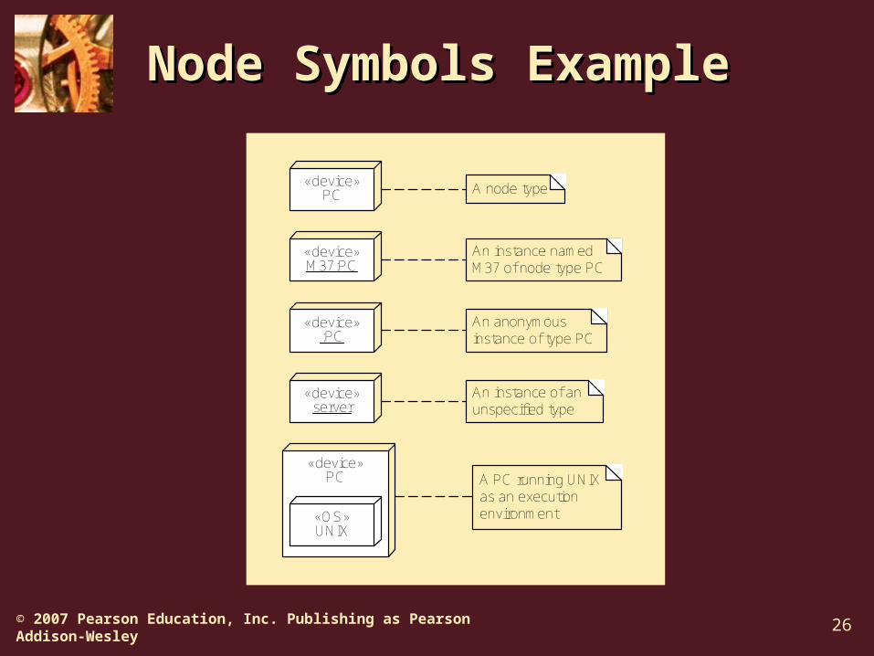
Node Symbols ExampleNode Symbols Example
«device»PC
«device»M37:PC
«device»:PC
«device»server
An instance of anunspecified type
An anonymousinstance of type PC
An instance namedM37 of node type PC
A node type
«device»PC A PC running UNIX
as an executionenvironment«OS»
UNIX

27© 2007 Pearson Education, Inc. Publishing as Pearson Addison-Wesley
Deployment DiagramsDeployment Diagrams
A UML deployment diagram models computational resources, communication paths among them, and artifacts that reside and execute on them.
Used to show • Real and virtual machines used in a system• Communication paths between machines• Program and data files realizing the system
Residence Execution

28© 2007 Pearson Education, Inc. Publishing as Pearson Addison-Wesley
Deployment Diagram Deployment Diagram RulesRules
Computational resources are nodes Communication paths are solid lines
between nodes• May be labeled• May have multiplicities and role names
Artifact symbols may • Appear within node symbols• Be listed within node symbols• Be connected to node symbols by
dependency arrows stereotyped with «deploy»
29© 2007 Pearson Education, Inc. Publishing as Pearson Addison-Wesley
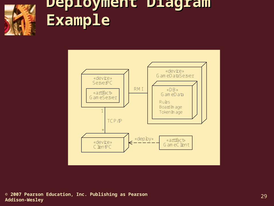
Deployment Diagram Deployment Diagram ExampleExample
«device»GameDataServer
«device»ClientPC
«artifact»GameClient
TCP/IP
«device»ServerPC
«artifact»GameServer
«DB»GameData
RulesBoardImageTokenImage
RMI
*
1
«deploy»
30© 2007 Pearson Education, Inc. Publishing as Pearson Addison-Wesley
SummarySummary
Box-and-line diagrams are used to make static and dynamic architectural models.
Notes, constraints, properties, and stereotypes can be used in any UML diagram.
Package diagrams are used to model modules and their parts.
Component diagrams are used to model software components.
Deployment diagrams are used to model physical architectures.