
取取取取りりりり扱扱扱扱いいいい説明書説明書 - Umbrella ......取取取取りりりり扱扱扱扱いいいい説明書説明書 (株)アンブレラカンパニー
Muffle Furnace Model
FO 100/200/300/310/410 /510/610/710/810
Instruction Manual
- Third Edition -
Yamato Scientific Co. LTD.,
This paper has been printed on recycled paper.
Thank you for purchasing "Muffle Furnace, FO Series" of Yamato Scientific Co., Ltd.
To use this unit properly, read this "Instruction Manual" thoroughly before using this unit. Keep this instruction manual around this unit for referring at anytime.
WARNING!: Carefully read and thoroughly understand the important warning items described in this manual before using this unit.
Contents
Cautions in Using with Safety................................................................1 • Explanation.................................................................................................................... 1 • Table of Illustrated Symbols .......................................................................................... 2 • Fundamental Matters of "WARNING!" and "CAUTION!" ............................................... 3
Before Using this unit .............................................................................4 • Requirements for Installation......................................................................................... 4
Description and Function of Each Part .................................................7 • Main Unit ....................................................................................................................... 7 • Control Panel................................................................................................................. 8 • Characters of the Controller .......................................................................................... 9
Operation Method .................................................................................10 • Operation Mode and Function List .............................................................................. 10 • Operation Mode, Function Setting Key, and Characters ............................................. 11 • Fixed Temperature Operation...................................................................................... 12 • Quick Auto Stop Operation.......................................................................................... 13 • Auto Stop Operation.................................................................................................... 14 • Auto Start Operation.................................................................................................... 16 • Program Operation...................................................................................................... 18 • Temperature Rise/Fall Curve (Reference)................................................................... 23 • Program Operation...................................................................................................... 26 • Other Functions........................................................................................................... 28
Handling Precautions ...........................................................................30
Maintenance Method.............................................................................32 • Daily Inspection and Maintenance .............................................................................. 32
Long storage and disposal...................................................................33 • When not using this unit for long term / When disposing ............................................ 33
In the Event of Failure… .......................................................................34 • Safety Device and Error Code..................................................................................... 34 • Trouble Shooting ......................................................................................................... 35
After Service and Warranty ..................................................................36
Specification..........................................................................................37 • FO100/200/300/310/410 ............................................................................................. 37 • FO510/610/710/810 .................................................................................................... 38 • Optional Accessories................................................................................................... 39
Wiring Diagram......................................................................................40
Replacement Parts Table......................................................................43
Reference...............................................................................................45 • List of Dangerous Substances .................................................................................... 45
1
Cautions in Using with Safety Explanation
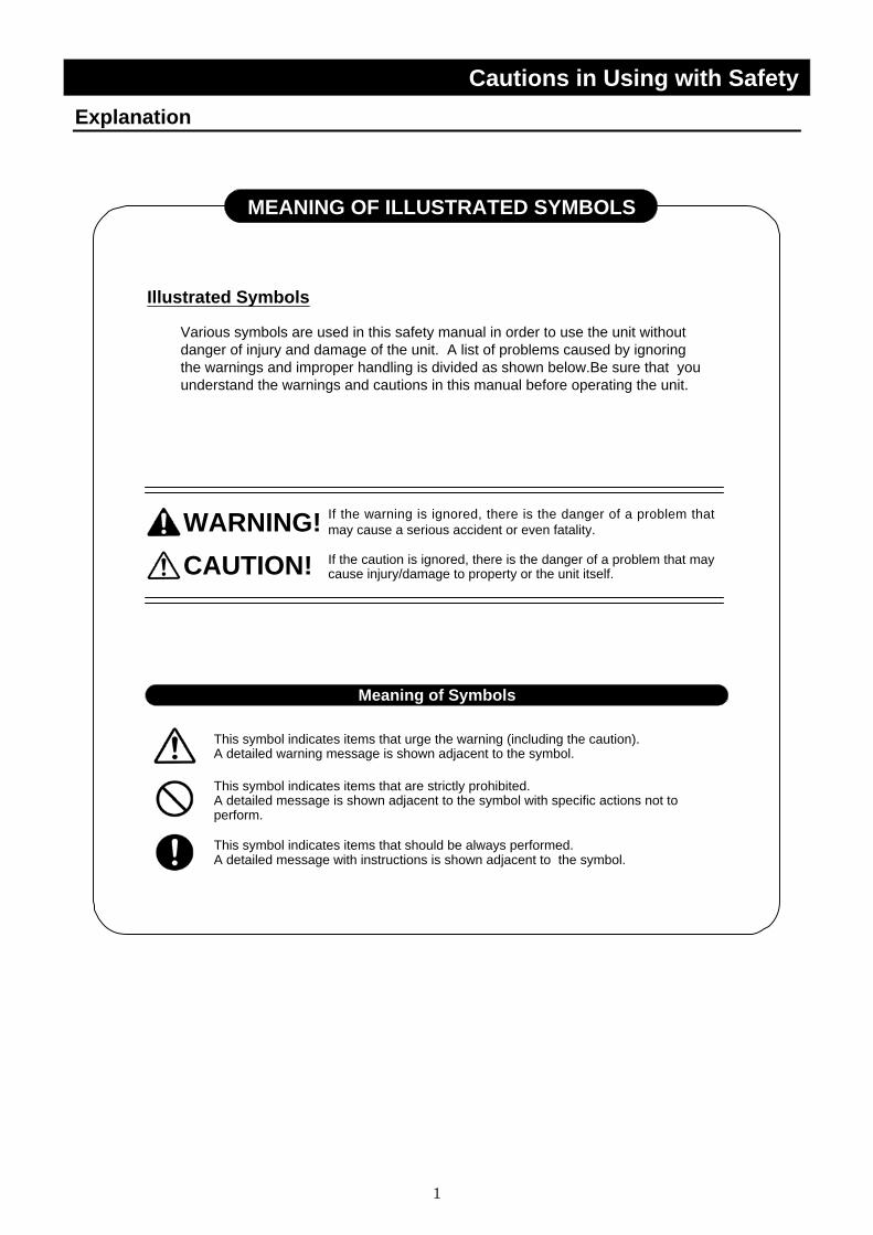
MEANING OF ILLUSTRATED SYMBOLS
Various symbols are used in this safety manual in order to use the unit withoutdanger of injury and damage of the unit. A list of problems caused by ignoringthe warnings and improper handling is divided as shown below.Be sure that youunderstand the warnings and cautions in this manual before operating the unit.
WARNING! If the warning is ignored, there is the danger of a problem thatmay cause a serious accident or even fatality.
CAUTION! If the caution is ignored, there is the danger of a problem that maycause injury/damage to property or the unit itself.
Meaning of Symbols
This symbol indicates items that urge the warning (including the caution).A detailed warning message is shown adjacent to the symbol.
This symbol indicates items that are strictly prohibited.A detailed message is shown adjacent to the symbol with specific actions not toperform.
This symbol indicates items that should be always performed.A detailed message with instructions is shown adjacent to the symbol.
Illustrated Symbols
2
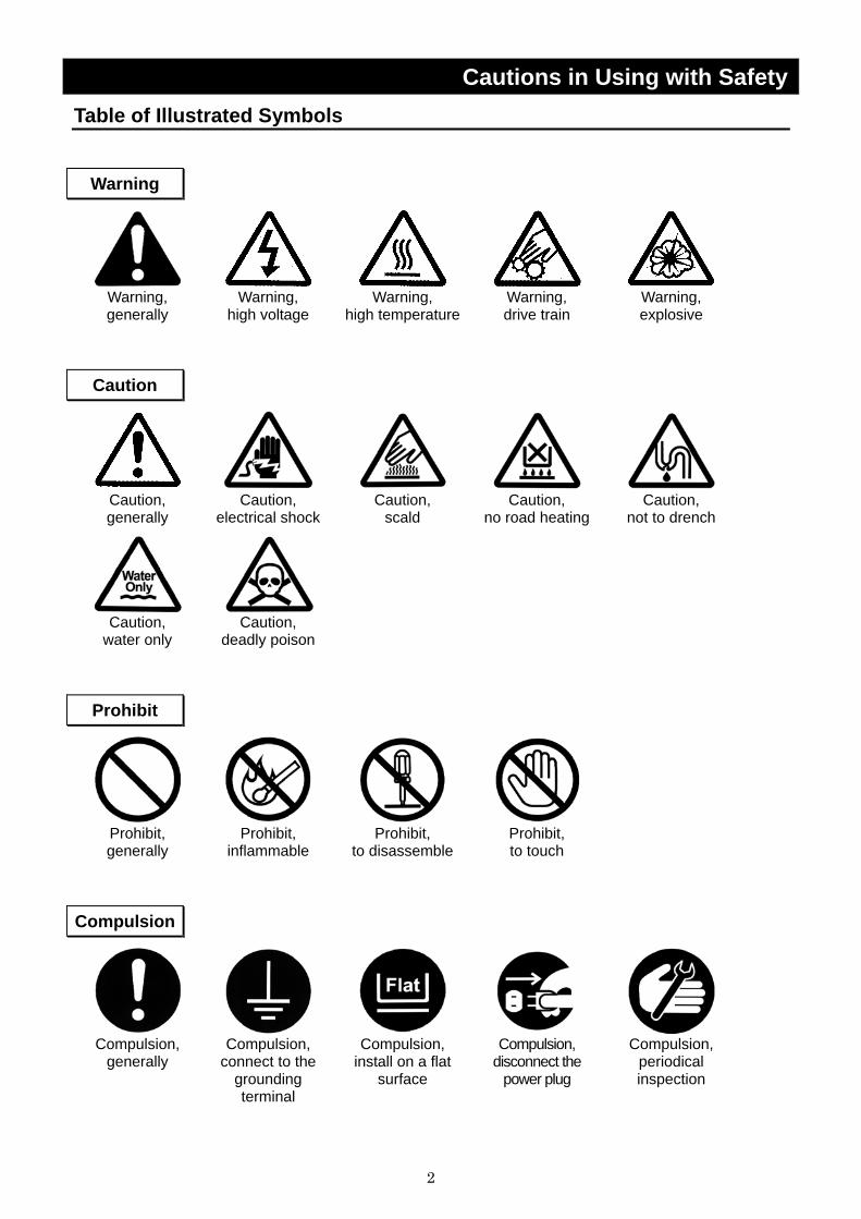
Cautions in Using with Safety Table of Illustrated Symbols
Warning
Warning, generally
Warning, high voltage
Warning, high temperature
Warning, drive train
Warning, explosive
Caution
Caution, generally
Caution, electrical shock
Caution, scald
Caution, no road heating
Caution, not to drench
Caution, water only
Caution, deadly poison
Prohibit
Prohibit, generally
Prohibit, inflammable
Prohibit, to disassemble
Prohibit, to touch
Compulsion
Compulsion,
generally Compulsion,
connect to the grounding terminal
Compulsion, install on a flat
surface
Compulsion, disconnect the
power plug
Compulsion, periodical inspection
3
Cautions in Using with Safety Fundamental Matters of "WARNING!" and "CAUTION!"
WARNING!
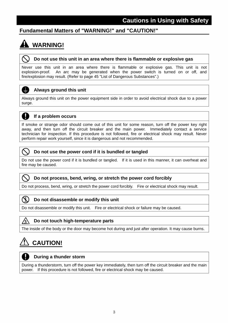
Do not use this unit in an area where there is flammable or explosive gas
Never use this unit in an area where there is flammable or explosive gas. This unit is not explosion-proof. An arc may be generated when the power switch is turned on or off, and fire/explosion may result. (Refer to page 45 "List of Dangerous Substances".)
Always ground this unit
Always ground this unit on the power equipment side in order to avoid electrical shock due to a power surge.
If a problem occurs
If smoke or strange odor should come out of this unit for some reason, turn off the power key right away, and then turn off the circuit breaker and the main power. Immediately contact a service technician for inspection. If this procedure is not followed, fire or electrical shock may result. Never perform repair work yourself, since it is dangerous and not recommended.
Do not use the power cord if it is bundled or tangled
Do not use the power cord if it is bundled or tangled. If it is used in this manner, it can overheat and fire may be caused.
Do not process, bend, wring, or stretch the power cord forcibly
Do not process, bend, wring, or stretch the power cord forcibly. Fire or electrical shock may result.
Do not disassemble or modify this unit
Do not disassemble or modify this unit. Fire or electrical shock or failure may be caused.
Do not touch high-temperature parts The inside of the body or the door may become hot during and just after operation. It may cause burns.
CAUTION!
During a thunder storm
During a thunderstorm, turn off the power key immediately, then turn off the circuit breaker and the main power. If this procedure is not followed, fire or electrical shock may be caused.

4
Before Using this unit Requirements for Installation
WARNING! 1. Always ground this unit
• Connect the power plug to a receptacle with grounding connectors. • Do not forget to ground this unit, to protect you and the unit from electrical shock in case of
power surge. Choose a receptacle with grounding connectors as often as possible. • Do not connect the grounding wire to a gas pipe, or by means of a lightning rod or telephone
line. A fire or electrical shock will occur. • Though FO200/300 model is the 100V single phase model, these two models have the large
electric capacity (over 15A). Be sure to prepare the power switchboard with the specific grand earth or specific receptacle which has electric capacity over 20A.
• FO310/410/510/610/710/810 model is the 200V single phase mode. Be sure to connect this model to the specific power switchboard or receptacle for 200V.
2. Choose a proper place for installation
• Do not install this unit in a place where:
♦ Rough or dirty surface. ♦ Flammable gas or corrosive gas is generated. ♦ Ambient temperature exceeds 35°C. ♦ Ambient temperature fluctuates violently. ♦ There is direct sunlight. ♦ There is excessive humidity and dust. ♦ There is a constant vibration.
• Install this unit on a stable place with the space as shown below.
More than 30cm
Front side
More than 30cm (also the reverse side)
More than1m
52cm
5
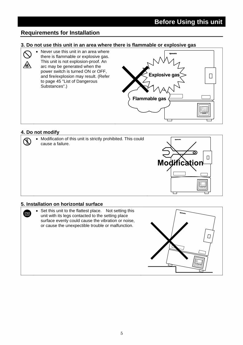
Before Using this unit Requirements for Installation 3. Do not use this unit in an area where there is flammable or explosive gas
• Never use this unit in an area where there is flammable or explosive gas. This unit is not explosion-proof. An arc may be generated when the power switch is turned ON or OFF, and fire/explosion may result. (Refer to page 45 "List of Dangerous Substances".)
4. Do not modify
• Modification of this unit is strictly prohibited. This could
cause a failure.
5. Installation on horizontal surface
• Set this unit to the flattest place. Not setting this
unit with its legs contacted to the setting place surface evenly could cause the vibration or noise, or cause the unexpectible trouble or malfunction.

6
Before Using this unit Requirements for Installation 6. Choose a correct power distribution board or receptacle
• Choose a correct power distribution board or receptacle that meets the unit’s rated electric capacity.
Electric capacity : FO100: AC100 V, 11A FO200: AC100 V, 16A FO300: AC100 V, 21A FO310: AC200 V (Single phase), 11A FO410: AC200 V (Single phase), 12A FO510: AC200 V (Single phase), 13.5A FO610: AC200 V (Single phase), 16A FO710: AC200 V (Single phase), 18.5A FO810: AC200 V (Single phase), 21A
NOTE) There could be the case that the unit does not run even after turning ON the power. Inspect whether the voltage of the main power is lowered than the specified value, or whether other device(s) uses the same power line of this unit. If the phenomena might be found, change the power line of this unit to the other power line.
7. Before/after installing
• It may cause injure to a person if this unit falls down or moves by the earthquake and the
impact. etc.. To prevent, take measures that the unit cannot fall down, and not install to busy place.
• Touching the unit may cause a burn during and after the operation. To prevent, take measures that putting up a notice of operating etc..
8. Handling of power code
• Do not entangle the power cord. This will cause overheating and possibly a fire. • Do not bend or twist the power cord, or apply excessive tension to it. This may cause a fire
and electrical shock. • Do not lay the power cord under a desk or chair, and do not allow it to be pinched in order to
prevent it from being damaged and to avoid a fire or electrical shock. • Keep the power cord away from any heating equipment such as a room heater. The cord's
insulation may melt and cause a fire or electrical shock.
• If the power cord becomes damaged (wiring exposed, breakage, etc.), immediately turn off the
power at the rear of this unit and shut off the main supply power. Then contact your nearest dealer for replacement of the power cord. Leaving it may cause a fire or electrical shock.
• Connect the power plug to the outlet which is supplied appropriate power and voltage.
7
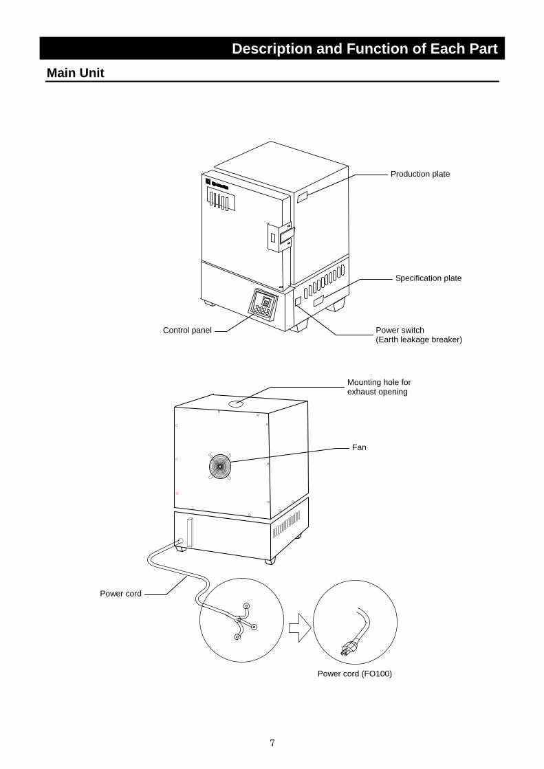
Description and Function of Each Part Main Unit
FO100のみ
Control panel
Power cord
Production plate
Mounting hole for exhaust opening
Power switch (Earth leakage breaker)
Specification plate
Fan
Power cord (FO100)

8
Description and Function of Each Part Control Panel
POWER
① START/STOP Key: Starts/stops the operation. ② ▲▼ Key: Uses for rising UP/lowering DOWN the setting value. ③ ENTER Key: Settles the inputted value. ④ FIXED TEMP Key: Chooses the fixed temperature operation. ⑤ TIMER Key: Chooses the timer operation (Quick Auto Stop/Auto Stop/Auto
Start). ⑥ PROGRAM Key: Chooses the program operation or program creation mode. ⑦ SUBMENU Key: Uses for setting the overheating prevention temperature,
calibration offset temperature, key lock function, or program repeat function.
⑧ HEATER Lamp: Lights while the heater works. ⑨ ALARM Lamp: Lights up when an error occurs. (Buzzer sounds simultaneously.) ⑩ AUTO STOP Lamp: Blinks while setting quick auto stop timer or auto stop timer.
Lights while quick auto stop timer or auto stop timer is running. ⑪ AUTO START Lamp: Blinks while setting auto start timer.
Lights while auto start timer is running. ⑫ FIXED TEMP Lamp: Blinks while setting fixed temperature operation.
Lights while fixed temperature operation is running. ⑬ PROGRAM Lamp: Blinks while setting program operation.
Lights while program operation is running. ⑭ Measurement Temperature
Display: Displays the measured temperature, setting character, alarm information.
⑮ Setting Temperature Display:
Displays the setting temperature, setting value for timer mode, remaining time.
⑯ Overheating Prevention Temperature Display:
Displays the setting temperature for overheating prevention device.
⑰ Power Switch: (Earth leakage breaker)
Turns ON/OFF the main power.
⑱ Electric leak testing button: Checks the breaker’s condition.
⑧ ⑨ ⑩ ⑪ ⑫ ⑬
③
②
④ ⑤
⑦
⑥
①
⑯
⑮
⑭
⑰
⑱
9
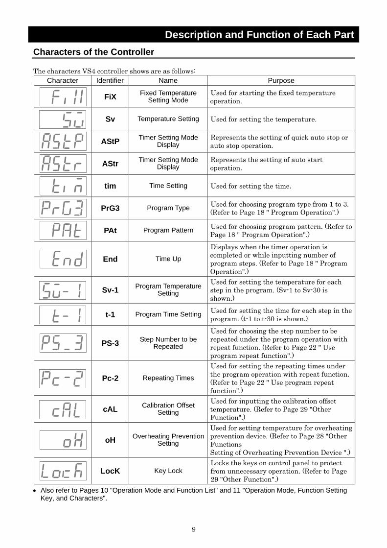
Description and Function of Each Part Characters of the Controller The characters VS4 controller shows are as follows:
Character Identifier Name Purpose
FiX Fixed Temperature
Setting Mode Used for starting the fixed temperature operation.
Sv Temperature Setting Used for setting the temperature.
AStP Timer Setting Mode
Display Represents the setting of quick auto stop or auto stop operation.
AStr Timer Setting Mode
Display Represents the setting of auto start operation.
tim Time Setting Used for setting the time.
PrG3 Program Type Used for choosing program type from 1 to 3.
(Refer to Page 18 " Program Operation".)
PAt Program Pattern Used for choosing program pattern. (Refer to
Page 18 " Program Operation".)
End Time Up
Displays when the timer operation is completed or while inputting number of program steps. (Refer to Page 18 " Program Operation".)
Sv-1 Program Temperature
Setting Used for setting the temperature for each step in the program. (Sv-1 to Sv-30 is shown.)
t-1 Program Time Setting Used for setting the time for each step in the
program. (t-1 to t-30 is shown.)
PS-3 Step Number to be
Repeated
Used for choosing the step number to be repeated under the program operation with repeat function. (Refer to Page 22 " Use program repeat function".)
Pc-2 Repeating Times
Used for setting the repeating times under the program operation with repeat function.(Refer to Page 22 " Use program repeat function".)
cAL Calibration Offset
Setting Used for inputting the calibration offset temperature. (Refer to Page 29 "Other Function".)
oH Overheating Prevention
Setting
Used for setting temperature for overheating prevention device. (Refer to Page 28 "Other Functions Setting of Overheating Prevention Device ".)
LocK Key Lock
Locks the keys on control panel to protect from unnecessary operation. (Refer to Page 29 "Other Function".)
• Also refer to Pages 10 "Operation Mode and Function List" and 11 "Operation Mode, Function Setting Key, and Characters".
10
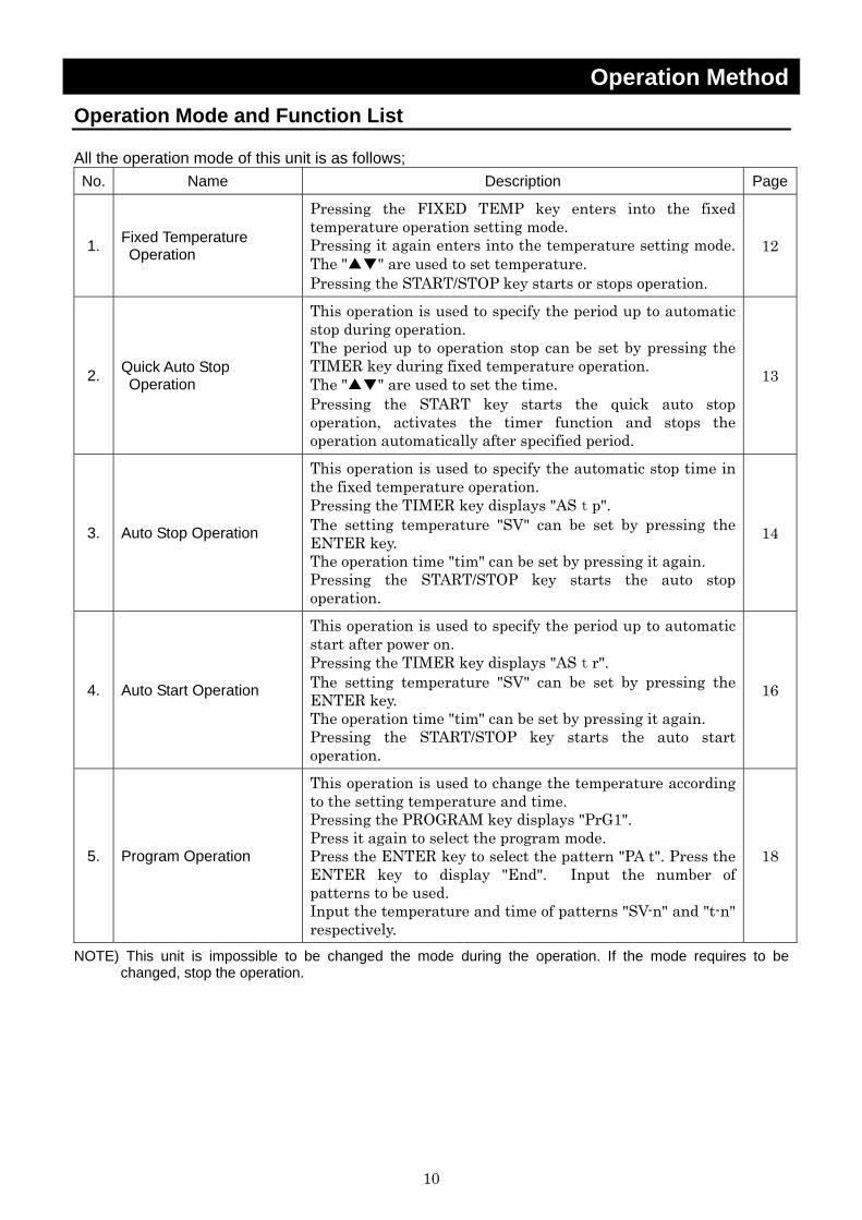
Operation Method Operation Mode and Function List All the operation mode of this unit is as follows; No. Name Description Page
1. Fixed Temperature Operation
Pressing the FIXED TEMP key enters into the fixed temperature operation setting mode. Pressing it again enters into the temperature setting mode. The "▲▼" are used to set temperature. Pressing the START/STOP key starts or stops operation.
12
2. Quick Auto Stop Operation
This operation is used to specify the period up to automatic stop during operation. The period up to operation stop can be set by pressing the TIMER key during fixed temperature operation. The "▲▼" are used to set the time. Pressing the START key starts the quick auto stop operation, activates the timer function and stops the operation automatically after specified period.
13
3. Auto Stop Operation
This operation is used to specify the automatic stop time in the fixed temperature operation. Pressing the TIMER key displays "AStp". The setting temperature "SV" can be set by pressing the ENTER key. The operation time "tim" can be set by pressing it again. Pressing the START/STOP key starts the auto stop operation.
14
4. Auto Start Operation
This operation is used to specify the period up to automatic start after power on. Pressing the TIMER key displays "AStr". The setting temperature "SV" can be set by pressing the ENTER key. The operation time "tim" can be set by pressing it again. Pressing the START/STOP key starts the auto start operation.
16
5. Program Operation
This operation is used to change the temperature according to the setting temperature and time. Pressing the PROGRAM key displays "PrG1". Press it again to select the program mode. Press the ENTER key to select the pattern "PA t". Press the ENTER key to display "End". Input the number of patterns to be used. Input the temperature and time of patterns "SV-n" and "t-n" respectively.
18
NOTE) This unit is impossible to be changed the mode during the operation. If the mode requires to be changed, stop the operation.

11
Operation Method Operation Mode, Function Setting Key, and Characters
The operation mode setting and function setting use the key operation and characters show in the following figure.
12
Operation Method Fixed Temperature Operation
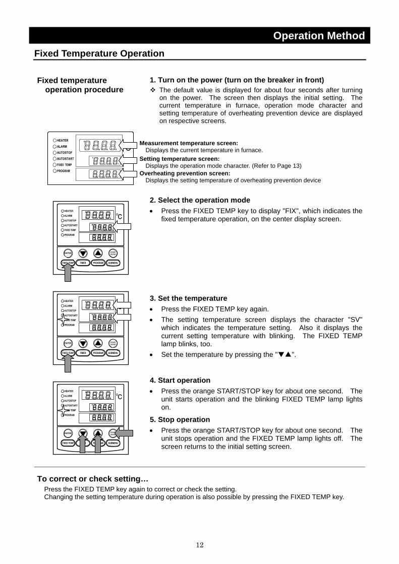
Fixed temperature operation procedure
1. Turn on the power (turn on the breaker in front) The default value is displayed for about four seconds after turning on the power. The screen then displays the initial setting. The current temperature in furnace, operation mode character and setting temperature of overheating prevention device are displayed on respective screens.
2. Select the operation mode • Press the FIXED TEMP key to display "FIX", which indicates the
fixed temperature operation, on the center display screen.
3. Set the temperature • Press the FIXED TEMP key again. • The setting temperature screen displays the character "SV"
which indicates the temperature setting. Also it displays the current setting temperature with blinking. The FIXED TEMP lamp blinks, too.
• Set the temperature by pressing the "▼▲".
4. Start operation • Press the orange START/STOP key for about one second. The
unit starts operation and the blinking FIXED TEMP lamp lights on.
5. Stop operation • Press the orange START/STOP key for about one second. The
unit stops operation and the FIXED TEMP lamp lights off. The screen returns to the initial setting screen.
To correct or check setting… Press the FIXED TEMP key again to correct or check the setting. Changing the setting temperature during operation is also possible by pressing the FIXED TEMP key.
Measurement temperature screen: Displays the current temperature in furnace. Setting temperature screen:
Displays the operation mode character. (Refer to Page 13) Overheating prevention screen: Displays the setting temperature of overheating prevention device
13
Operation Method Quick Auto Stop Operation
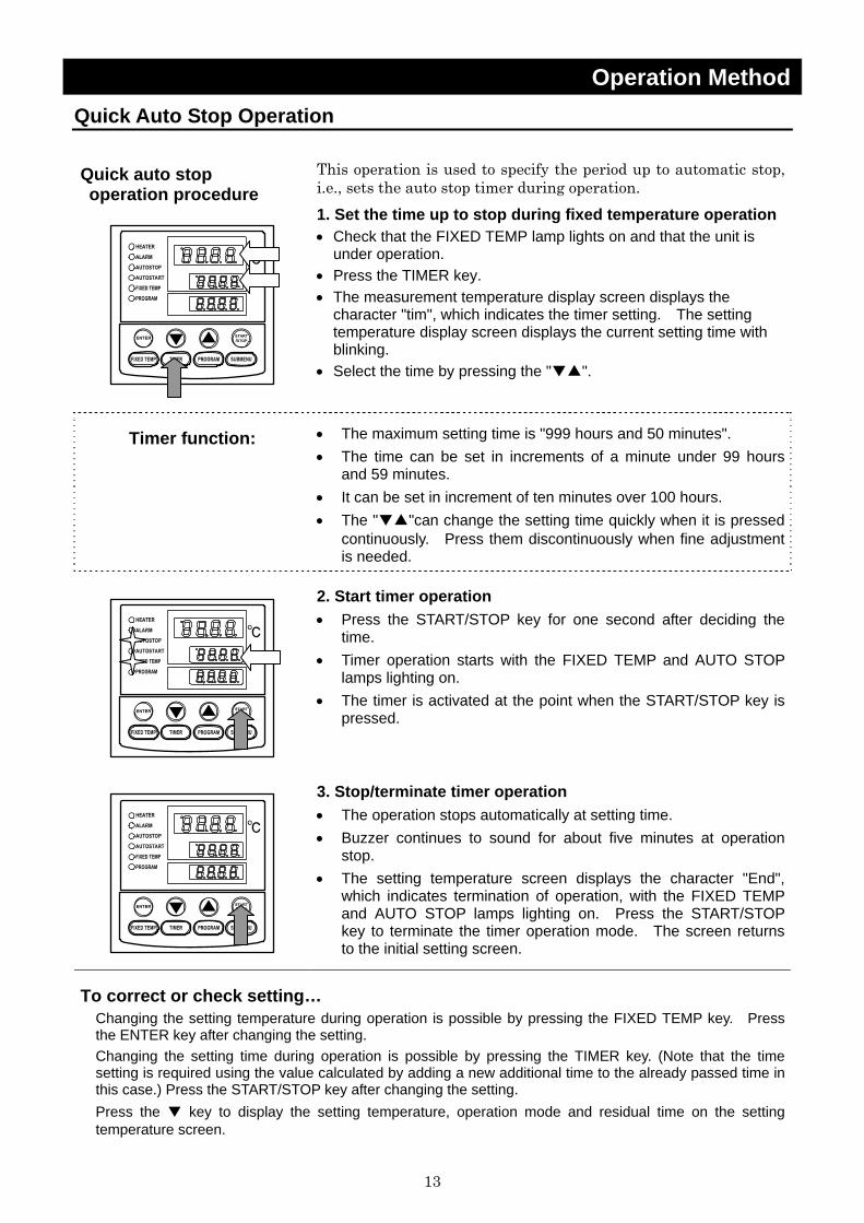
Quick auto stop operation procedure
This operation is used to specify the period up to automatic stop, i.e., sets the auto stop timer during operation. 1. Set the time up to stop during fixed temperature operation • Check that the FIXED TEMP lamp lights on and that the unit is
under operation. • Press the TIMER key. • The measurement temperature display screen displays the
character "tim", which indicates the timer setting. The setting temperature display screen displays the current setting time with blinking.
• Select the time by pressing the "▼▲".
Timer function: • The maximum setting time is "999 hours and 50 minutes". • The time can be set in increments of a minute under 99 hours
and 59 minutes. • It can be set in increment of ten minutes over 100 hours. • The "▼▲"can change the setting time quickly when it is pressed
continuously. Press them discontinuously when fine adjustment is needed.
2. Start timer operation • Press the START/STOP key for one second after deciding the
time. • Timer operation starts with the FIXED TEMP and AUTO STOP
lamps lighting on. • The timer is activated at the point when the START/STOP key is
pressed.
3. Stop/terminate timer operation • The operation stops automatically at setting time. • Buzzer continues to sound for about five minutes at operation
stop. • The setting temperature screen displays the character "End",
which indicates termination of operation, with the FIXED TEMP and AUTO STOP lamps lighting on. Press the START/STOP key to terminate the timer operation mode. The screen returns to the initial setting screen.
To correct or check setting… Changing the setting temperature during operation is possible by pressing the FIXED TEMP key. Press the ENTER key after changing the setting. Changing the setting time during operation is possible by pressing the TIMER key. (Note that the time setting is required using the value calculated by adding a new additional time to the already passed time in this case.) Press the START/STOP key after changing the setting. Press the ▼ key to display the setting temperature, operation mode and residual time on the setting temperature screen.

14
Operation Method Auto Stop Operation
Auto stop operation procedure
This operation is used to specify the automatic stop time in the fixed temperature operation. 1. Set stop time ① Press the TIMER key on the initial screen.
Press the TIMER key again. The setting temperature display screen displays the character "AstP", which indicates the auto stop operation, with blinking.
② Press the ENTER key. The measurement temperature screen displays the character "SV", which indicates the temperature setting. The setting temperature screen displays the current setting temperature with blinking. The AUTO STOP lamp blinks, too.
③ Set the temperature using the "▼▲". ④ Press the ENTER key again.
The measurement temperature display screen displays the character "tim", which indicates the timer setting. The setting temperature display screen displays the current setting time with blinking.
⑤ Set the time using the "▼▲".
Timer function: • The maximum setting time is "999 hours and 50 minutes". • The time can be set in increments of a minute under 99 hours
and 59 minutes. • It can be set in increment of ten minutes over 100 hours. • The "▼▲"can change the setting time quickly when it is pressed
continuously. Press them discontinuously when fine adjustment is needed.
2. Start timer operation • Press the START/STOP key for one second after deciding the
time. • Timer operation starts with the AUTO STOP lamp lighting on. • The timer is activated at the point when the temperature in
furnace (measurement temperature) reaches to the setting temperature.
15
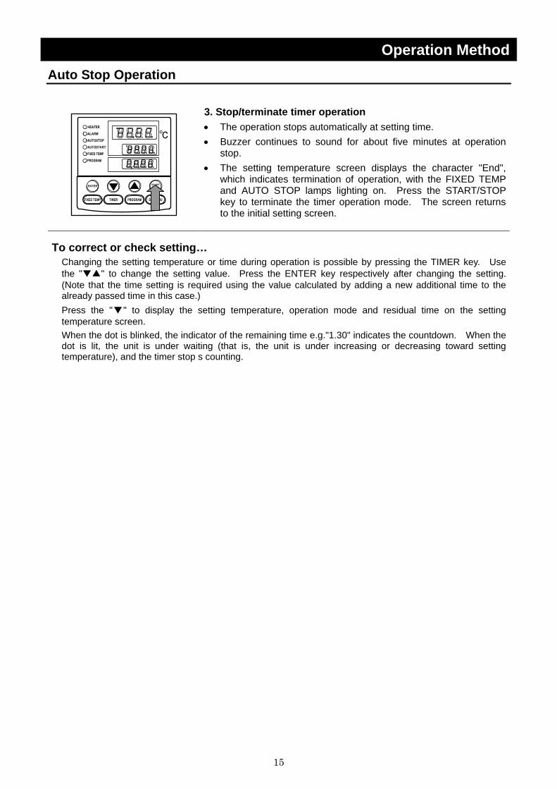
Operation Method Auto Stop Operation
3. Stop/terminate timer operation • The operation stops automatically at setting time. • Buzzer continues to sound for about five minutes at operation
stop. • The setting temperature screen displays the character "End",
which indicates termination of operation, with the FIXED TEMP and AUTO STOP lamps lighting on. Press the START/STOP key to terminate the timer operation mode. The screen returns to the initial setting screen.
To correct or check setting… Changing the setting temperature or time during operation is possible by pressing the TIMER key. Use the "▼▲" to change the setting value. Press the ENTER key respectively after changing the setting. (Note that the time setting is required using the value calculated by adding a new additional time to the already passed time in this case.) Press the "▼" to display the setting temperature, operation mode and residual time on the setting temperature screen. When the dot is blinked, the indicator of the remaining time e.g."1.30" indicates the countdown. When the dot is lit, the unit is under waiting (that is, the unit is under increasing or decreasing toward setting temperature), and the timer stop s counting.
16
Operation Method Auto Start Operation
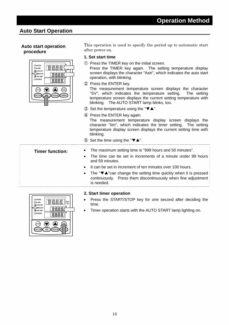
Auto start operation procedure
This operation is used to specify the period up to automatic start after power on. 1. Set start time ① Press the TIMER key on the initial screen.
Press the TIMER key again. The setting temperature display screen displays the character "Astr", which indicates the auto start operation, with blinking.
② Press the ENTER key. The measurement temperature screen displays the character "SV", which indicates the temperature setting. The setting temperature screen displays the current setting temperature with blinking. The AUTO START lamp blinks, too.
③ Set the temperature using the "▼▲". ④ Press the ENTER key again.
The measurement temperature display screen displays the character "tim", which indicates the timer setting. The setting temperature display screen displays the current setting time with blinking.
⑤ Set the time using the "▼▲".
Timer function: • The maximum setting time is "999 hours and 50 minutes". • The time can be set in increments of a minute under 99 hours
and 59 minutes. • It can be set in increment of ten minutes over 100 hours. • The "▼▲"can change the setting time quickly when it is pressed
continuously. Press them discontinuously when fine adjustment is needed.
2. Start timer operation • Press the START/STOP key for one second after deciding the
time. • Timer operation starts with the AUTO START lamp lighting on.

17
Operation Method Auto Start Operation
3. Stop/terminate timer operation • The operation starts automatically at setting time. • Press the START/STOP key for one second to stop or terminate
operation. The screen returns to the initial setting screen.
To correct or check setting… Changing the setting temperature or time during operation is possible by pressing the TIMER key. Use the "▼▲" to change the setting value. Press the ENTER key respectively after changing the setting. (Note that the time setting is required using the value calculated by adding a new additional time to the already passed time in this case.) Press the "▼" to display the setting temperature, operation mode and residual time on the setting temperature screen. Note that the setting condition is impossible to change once starting the operation after passing the auto start operation time. In this case, stop the operation by pressing START/STOP key, and reset to initial status.
18
Operation Method Program Operation
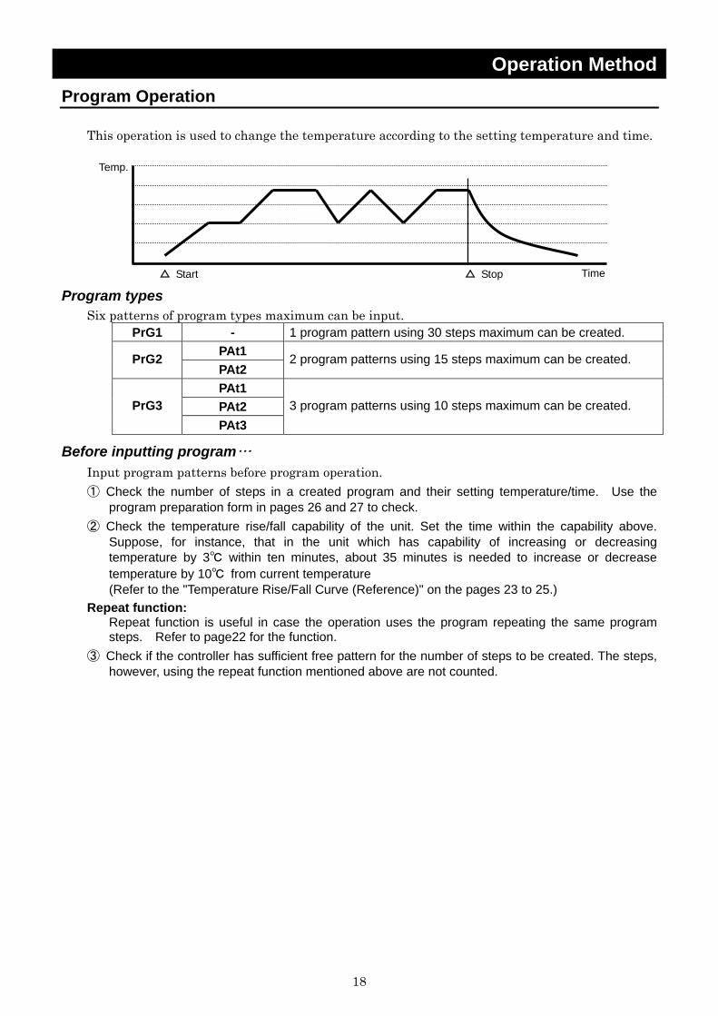
This operation is used to change the temperature according to the setting temperature and time.
Program types Six patterns of program types maximum can be input.
PrG1 - 1 program pattern using 30 steps maximum can be created. PAt1 PrG2 PAt2
2 program patterns using 15 steps maximum can be created.
PAt1 PAt2 PrG3 PAt3
3 program patterns using 10 steps maximum can be created.
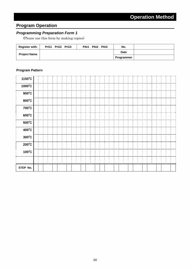
Before inputting program… Input program patterns before program operation. ① Check the number of steps in a created program and their setting temperature/time. Use the
program preparation form in pages 26 and 27 to check. ② Check the temperature rise/fall capability of the unit. Set the time within the capability above.
Suppose, for instance, that in the unit which has capability of increasing or decreasing temperature by 3℃ within ten minutes, about 35 minutes is needed to increase or decrease temperature by 10℃ from current temperature (Refer to the "Temperature Rise/Fall Curve (Reference)" on the pages 23 to 25.)
Repeat function: Repeat function is useful in case the operation uses the program repeating the same program steps. Refer to page22 for the function.
③ Check if the controller has sufficient free pattern for the number of steps to be created. The steps, however, using the repeat function mentioned above are not counted.
Temp.
Time△ Stop △ Start
19
Operation Method Program Operation Program creation
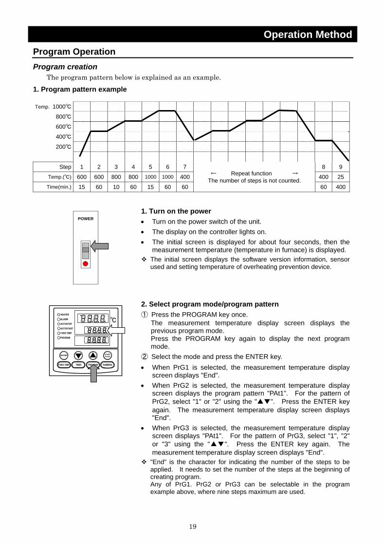
The program pattern below is explained as an example. 1. Program pattern example Temp. 1000℃
800℃
600℃
400℃
200℃
Step 1 2 3 4 5 6 7 8 9
Temp.(℃) 600 600 800 800 1000 1000 400 400 25
Time(min.) 15 60 10 60 15 60 60
← Repeat function → The number of steps is not counted.
60 400
POWER
1. Turn on the power • Turn on the power switch of the unit. • The display on the controller lights on. • The initial screen is displayed for about four seconds, then the
measurement temperature (temperature in furnace) is displayed. The initial screen displays the software version information, sensor used and setting temperature of overheating prevention device.
2. Select program mode/program pattern ① Press the PROGRAM key once.
The measurement temperature display screen displays the previous program mode. Press the PROGRAM key again to display the next program mode.
② Select the mode and press the ENTER key. • When PrG1 is selected, the measurement temperature display
screen displays "End". • When PrG2 is selected, the measurement temperature display
screen displays the program pattern "PAt1". For the pattern of PrG2, select "1" or "2" using the "▲▼". Press the ENTER key again. The measurement temperature display screen displays "End".
• When PrG3 is selected, the measurement temperature display screen displays "PAt1". For the pattern of PrG3, select "1", "2" or "3" using the "▲▼". Press the ENTER key again. The measurement temperature display screen displays "End".
"End" is the character for indicating the number of the steps to be applied. It needs to set the number of the steps at the beginning of creating program. Any of PrG1. PrG2 or PrG3 can be selectable in the program example above, where nine steps maximum are used.
20
Operation Method Program Operation
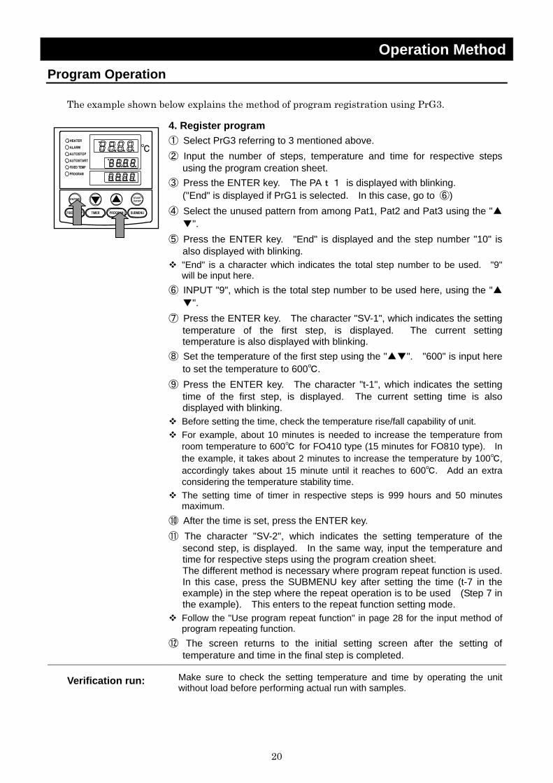
The example shown below explains the method of program registration using PrG3.
4. Register program ① Select PrG3 referring to 3 mentioned above. ② Input the number of steps, temperature and time for respective steps
using the program creation sheet. ③ Press the ENTER key. The PAt1 is displayed with blinking.
("End" is displayed if PrG1 is selected. In this case, go to ⑥) ④ Select the unused pattern from among Pat1, Pat2 and Pat3 using the "▲
▼". ⑤ Press the ENTER key. "End" is displayed and the step number "10" is
also displayed with blinking. "End" is a character which indicates the total step number to be used. "9" will be input here.
⑥ INPUT "9", which is the total step number to be used here, using the "▲▼".
⑦ Press the ENTER key. The character "SV-1", which indicates the setting temperature of the first step, is displayed. The current setting temperature is also displayed with blinking.
⑧ Set the temperature of the first step using the "▲▼". "600" is input here to set the temperature to 600℃.
⑨ Press the ENTER key. The character "t-1", which indicates the setting time of the first step, is displayed. The current setting time is also displayed with blinking.
Before setting the time, check the temperature rise/fall capability of unit. For example, about 10 minutes is needed to increase the temperature from room temperature to 600℃ for FO410 type (15 minutes for FO810 type). In the example, it takes about 2 minutes to increase the temperature by 100℃, accordingly takes about 15 minute until it reaches to 600℃. Add an extra considering the temperature stability time.
The setting time of timer in respective steps is 999 hours and 50 minutes maximum.
⑩ After the time is set, press the ENTER key. ⑪ The character "SV-2", which indicates the setting temperature of the
second step, is displayed. In the same way, input the temperature and time for respective steps using the program creation sheet. The different method is necessary where program repeat function is used. In this case, press the SUBMENU key after setting the time (t-7 in the example) in the step where the repeat operation is to be used (Step 7 in the example). This enters to the repeat function setting mode.
Follow the "Use program repeat function" in page 28 for the input method of program repeating function.
⑫ The screen returns to the initial setting screen after the setting of temperature and time in the final step is completed.
Verification run: Make sure to check the setting temperature and time by operating the unit without load before performing actual run with samples.
21
Operation Method Program Operation
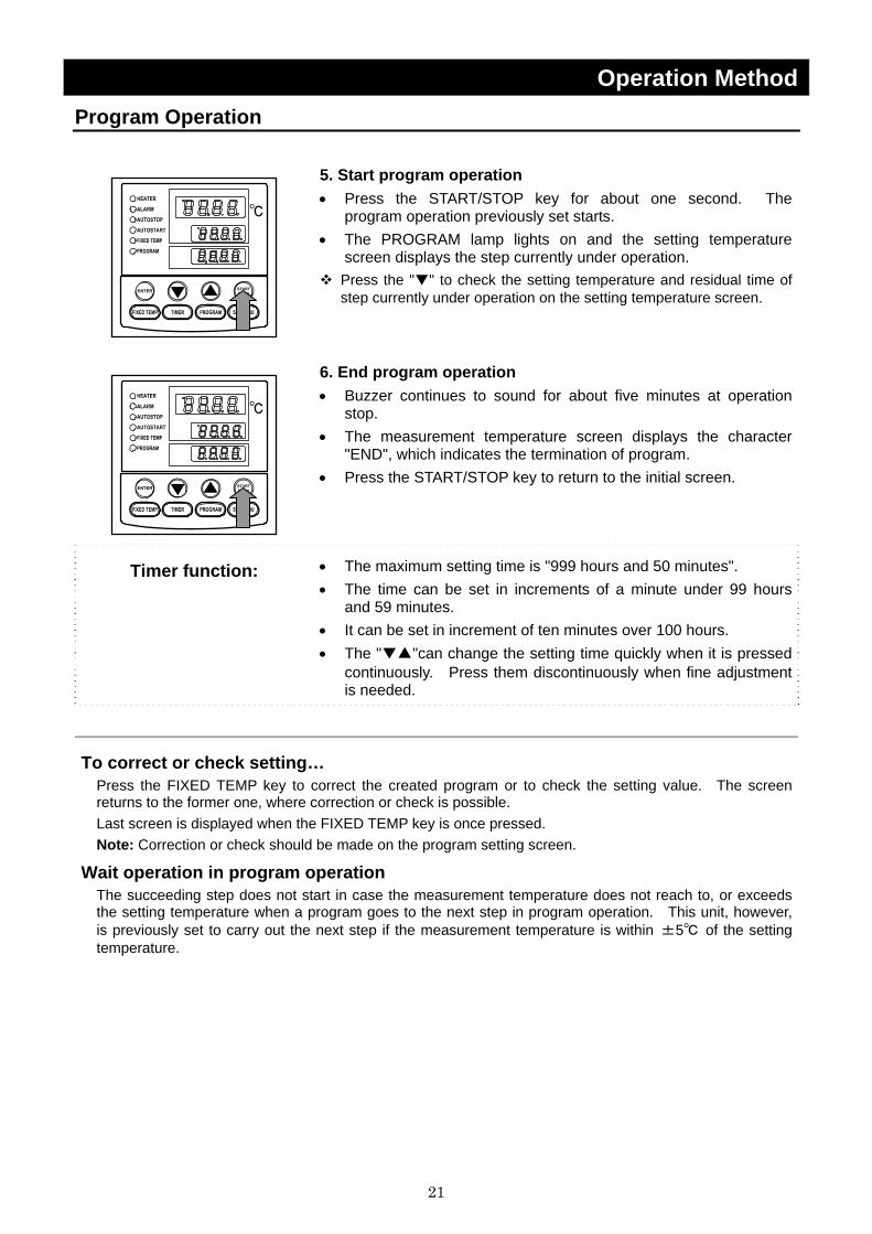
5. Start program operation • Press the START/STOP key for about one second. The
program operation previously set starts. • The PROGRAM lamp lights on and the setting temperature
screen displays the step currently under operation. Press the "▼" to check the setting temperature and residual time of step currently under operation on the setting temperature screen.
6. End program operation • Buzzer continues to sound for about five minutes at operation
stop. • The measurement temperature screen displays the character
"END", which indicates the termination of program. • Press the START/STOP key to return to the initial screen.
Timer function: • The maximum setting time is "999 hours and 50 minutes". • The time can be set in increments of a minute under 99 hours
and 59 minutes. • It can be set in increment of ten minutes over 100 hours. • The "▼▲"can change the setting time quickly when it is pressed
continuously. Press them discontinuously when fine adjustment is needed.
To correct or check setting… Press the FIXED TEMP key to correct the created program or to check the setting value. The screen returns to the former one, where correction or check is possible. Last screen is displayed when the FIXED TEMP key is once pressed. Note: Correction or check should be made on the program setting screen.
Wait operation in program operation The succeeding step does not start in case the measurement temperature does not reach to, or exceeds the setting temperature when a program goes to the next step in program operation. This unit, however, is previously set to carry out the next step if the measurement temperature is within ±5℃ of the setting temperature.

22
Operation Method Program Operation Use program repeat function
This section explains how to register the program repeat (repeating a program pattern) in program operation.
This section explains the registration procedure of program using repeat function in "4. Register program" above. The procedure sets the step number to be repeated "PS-n" and repeating times "Pc-n"(n: step number) ① Press the SUBMENU key in stead of the ENTER key after setting
the time (t-7 in the example) in the step where the repeat operation is to be used (Step 7 in the example). This enters to the repeat function setting mode.
② The measurement temperature screen displays the character "PS-n", which indicates the step to be repeated in the program pattern. The measurement temperature screen indicates "PS-7" in the example because repeat function is used at the seventh step. The step number 1 to 7 can be input in the setting temperature display screen. Enter the number (1 in the example) using the "▲▼".
③ Press the SUBMENU key. The measurement temperature screen displays the character "Pc-n", which indicates the repeating times. Enter the value of repeating times (2 in the example)with the "▲▼".
④ The screen goes to that for the next step when the SUBMENU key is pressed again. The screen to input the Sv-8 is displayed next in the example.
To correct or check setting… Correction of setting during the repeat setting mode is impossible. To correct or check the setting, end the setting of step currently input. Press the FIXED TEMP key after the temperature setting screen for the next step appears. The screen returns to the former one and re-setting is possible. Note: Correction or check should be made on the program setting screen.
23
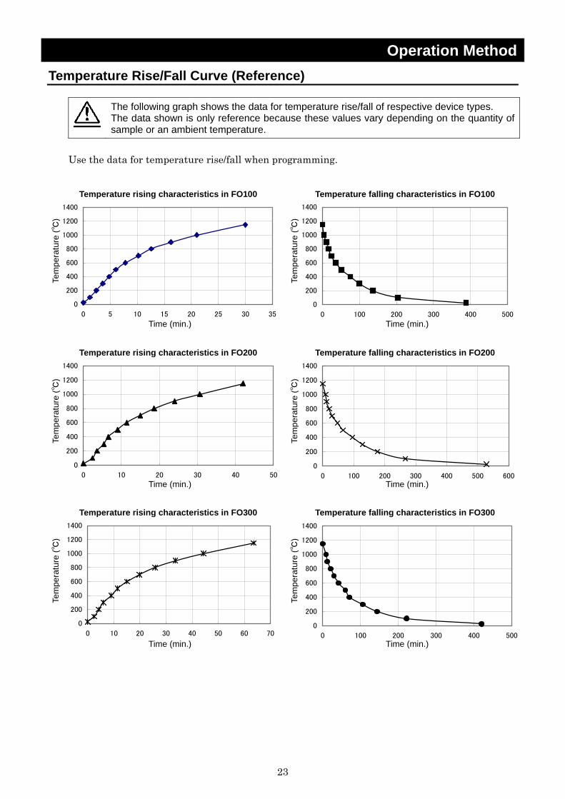
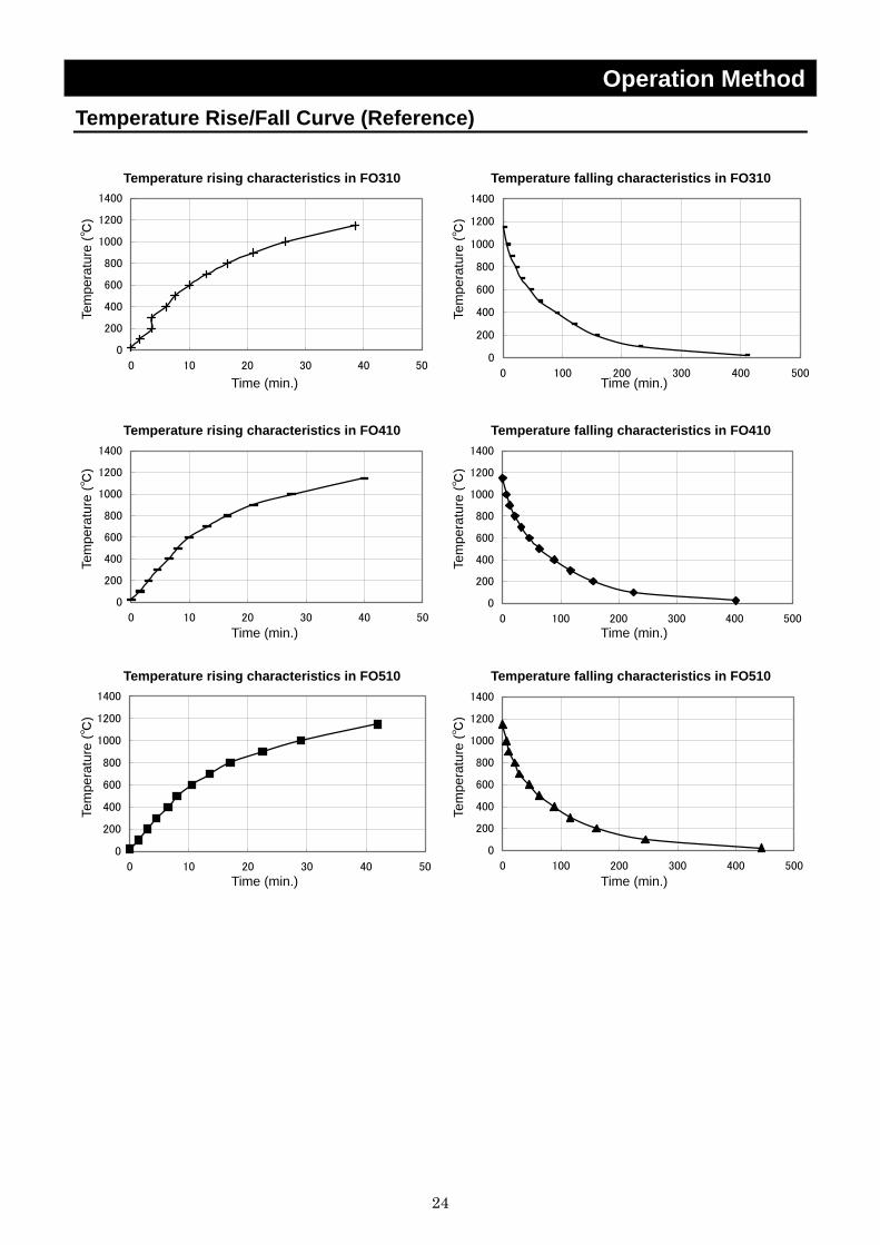
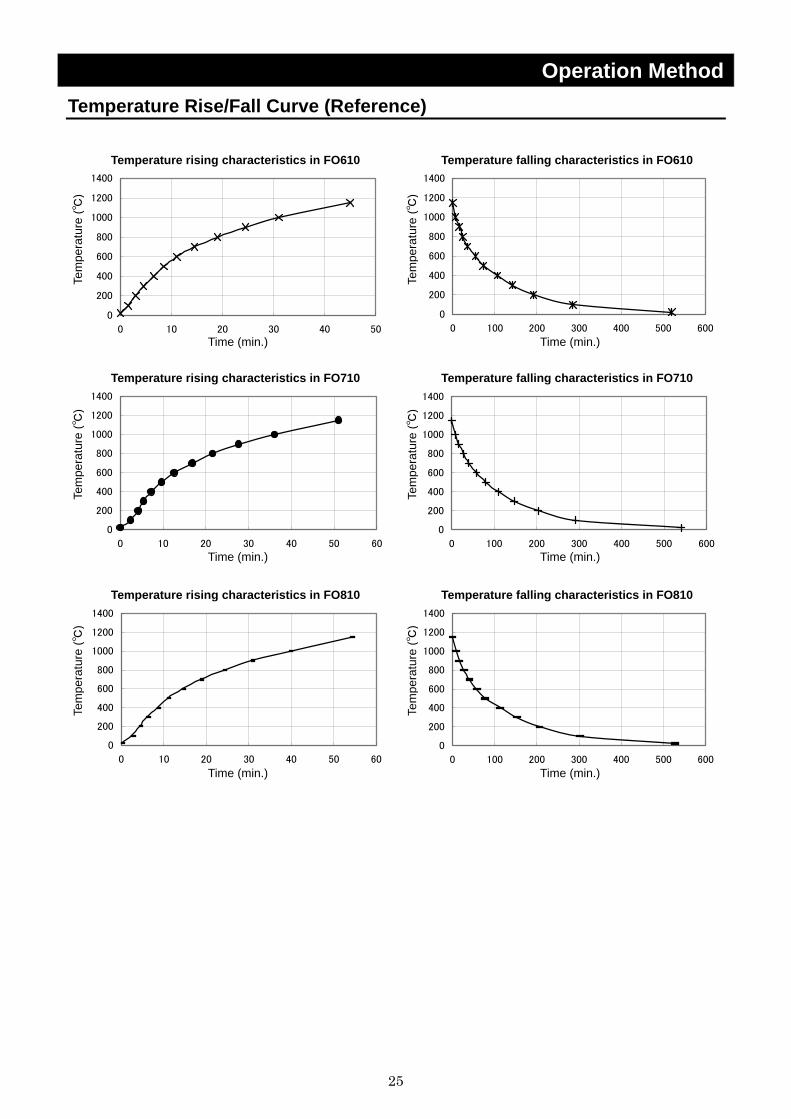
Operation Method Temperature Rise/Fall Curve (Reference)
The following graph shows the data for temperature rise/fall of respective device types. The data shown is only reference because these values vary depending on the quantity of sample or an ambient temperature.
Use the data for temperature rise/fall when programming.
Temperature rising characteristics in FO100
0
200
400
600
800
1000
1200
1400
0 5 10 15 20 25 30 35
Temperature falling characteristics in FO100
0
200
400
600
800
1000
1200
1400
0 100 200 300 400 500
Temperature rising characteristics in FO200
0
200
400
600
800
1000
1200
1400
0 10 20 30 40 50
Temperature falling characteristics in FO200
0
200
400
600
800
1000
1200
1400
0 100 200 300 400 500 600
Temperature rising characteristics in FO300
0
200
400
600
800
1000
1200
1400
0 10 20 30 40 50 60 70
Temperature falling characteristics in FO300
0
200
400
600
800
1000
1200
1400
0 100 200 300 400 500
Time (min.)
Tem
pera
ture
(℃)
Time (min.)
Tem
pera
ture
(℃)
Time (min.)
Tem
pera
ture
(℃)
Time (min.)
Tem
pera
ture
(℃)
Time (min.)
Tem
pera
ture
(℃)
Time (min.)
Tem
pera
ture
(℃)
24
Operation Method Temperature Rise/Fall Curve (Reference)
Temperature rising characteristics in FO310
0
200
400
600
800
1000
1200
1400
0 10 20 30 40 50
Temperature falling characteristics in FO310
0
200
400
600
800
1000
1200
1400
0 100 200 300 400 500
Temperature rising characteristics in FO410
0
200
400
600
800
1000
1200
1400
0 10 20 30 40 50
Temperature falling characteristics in FO410
0
200
400
600
800
1000
1200
1400
0 100 200 300 400 500
Temperature rising characteristics in FO510
0
200
400
600
800
1000
1200
1400
0 10 20 30 40 50
Temperature falling characteristics in FO510
0
200
400
600
800
1000
1200
1400
0 100 200 300 400 500
Time (min.)
Tem
pera
ture
(℃)
Time (min.)
Tem
pera
ture
(℃)
Time (min.)
Tem
pera
ture
(℃)
Time (min.)
Tem
pera
ture
(℃)
Time (min.)
Tem
pera
ture
(℃)
Time (min.)
Tem
pera
ture
(℃)
25
Operation Method Temperature Rise/Fall Curve (Reference)
Temperature rising characteristics in FO610
0
200
400
600
800
1000
1200
1400
0 10 20 30 40 50
Temperature falling characteristics in FO610
0
200
400
600
800
1000
1200
1400
0 100 200 300 400 500 600
Temperature rising characteristics in FO710
0
200
400
600
800
1000
1200
1400
0 10 20 30 40 50 60
Temperature falling characteristics in FO710
0
200
400
600
800
1000
1200
1400
0 100 200 300 400 500 600
Temperature rising characteristics in FO810
0
200
400
600
800
1000
1200
1400
0 10 20 30 40 50 60
Temperature falling characteristics in FO810
0
200
400
600
800
1000
1200
1400
0 100 200 300 400 500 600
Time (min.)
Tem
pera
ture
(℃)
Time (min.)
Tem
pera
ture
(℃)
Time (min.)
Tem
pera
ture
(℃)
Time (min.)
Tem
pera
ture
(℃)
Time (min.)
Tem
pera
ture
(℃)
Time (min.)
Tem
pera
ture
(℃)
26
Operation Method Program Operation Programming Preparation Form 1
(Please use this form by making copies)
Register with: PrG1 PrG2 PrG3 PAt1 PAt2 PAt3 No.
Date Project Name
Programmer
Program Pattern
1150℃
1000℃
900℃
800℃
700℃
600℃
500℃
400℃
300℃
200℃
100℃
STEP No.
27
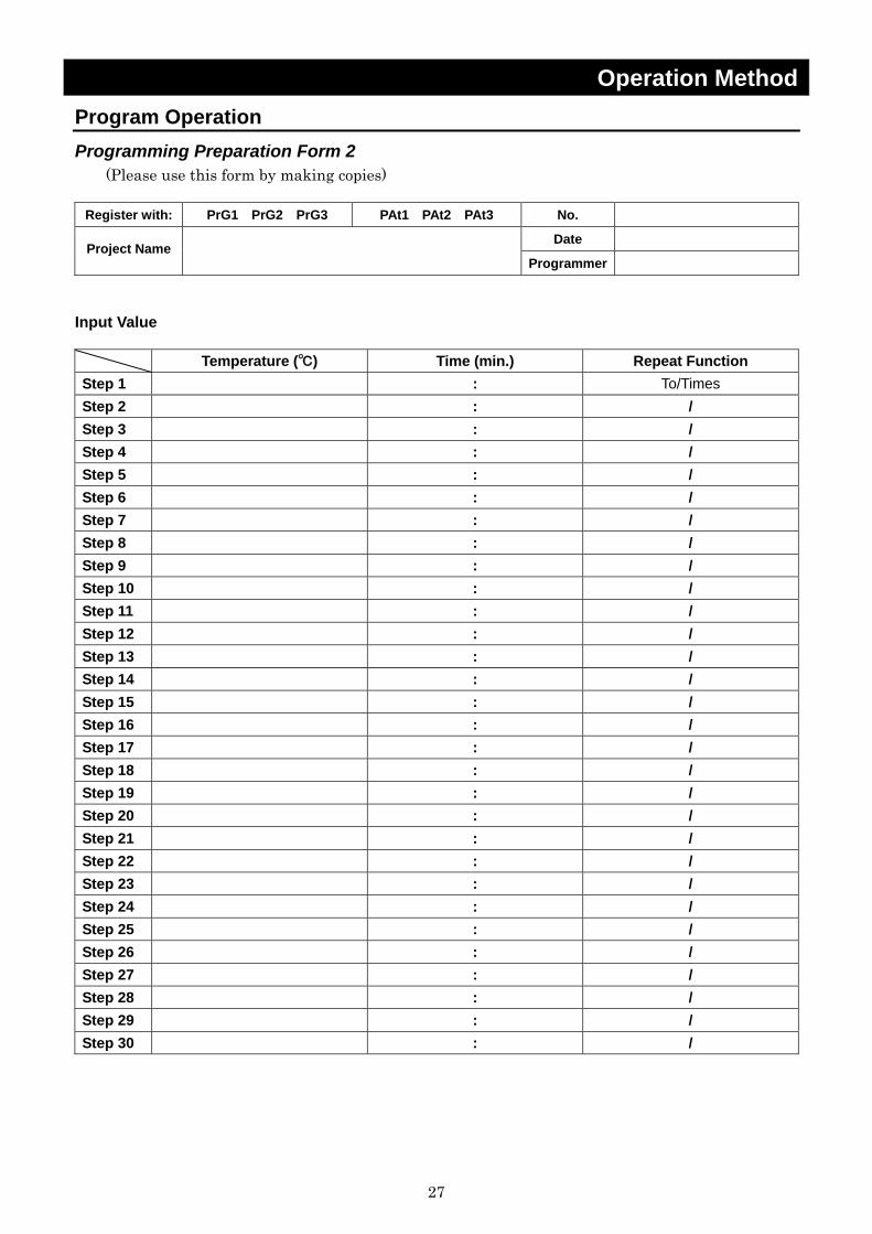
Operation Method Program Operation Programming Preparation Form 2
(Please use this form by making copies)
Register with: PrG1 PrG2 PrG3 PAt1 PAt2 PAt3 No.
Date Project Name
Programmer
Input Value Temperature (℃) Time (min.) Repeat Function Step 1 : To/Times Step 2 : / Step 3 : / Step 4 : / Step 5 : / Step 6 : / Step 7 : / Step 8 : / Step 9 : / Step 10 : / Step 11 : / Step 12 : / Step 13 : / Step 14 : / Step 15 : / Step 16 : / Step 17 : / Step 18 : / Step 19 : / Step 20 : / Step 21 : / Step 22 : / Step 23 : / Step 24 : / Step 25 : / Step 26 : / Step 27 : / Step 28 : / Step 29 : / Step 30 : /
28
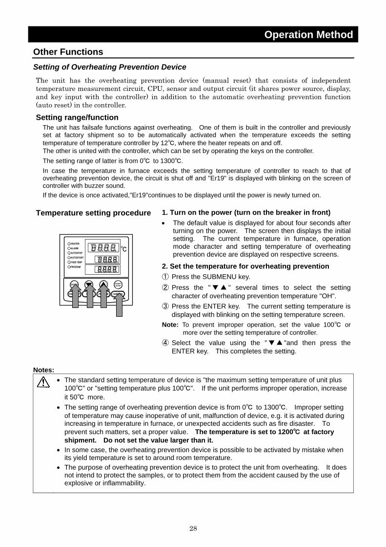
Operation Method Other Functions Setting of Overheating Prevention Device The unit has the overheating prevention device (manual reset) that consists of independent temperature measurement circuit, CPU, sensor and output circuit (it shares power source, display, and key input with the controller) in addition to the automatic overheating prevention function (auto reset) in the controller.
Setting range/function The unit has failsafe functions against overheating. One of them is built in the controller and previously set at factory shipment so to be automatically activated when the temperature exceeds the setting temperature of temperature controller by 12℃, where the heater repeats on and off. The other is united with the controller, which can be set by operating the keys on the controller. The setting range of latter is from 0℃ to 1300℃. In case the temperature in furnace exceeds the setting temperature of controller to reach to that of overheating prevention device, the circuit is shut off and "Er19" is displayed with blinking on the screen of controller with buzzer sound. If the device is once activated,"Er19"continues to be displayed until the power is newly turned on.
Temperature setting procedure
1. Turn on the power (turn on the breaker in front) • The default value is displayed for about four seconds after
turning on the power. The screen then displays the initial setting. The current temperature in furnace, operation mode character and setting temperature of overheating prevention device are displayed on respective screens.
2. Set the temperature for overheating prevention ① Press the SUBMENU key. ② Press the " ▼▲ " several times to select the setting
character of overheating prevention temperature "OH". ③ Press the ENTER key. The current setting temperature is
displayed with blinking on the setting temperature screen. Note: To prevent improper operation, set the value 100℃ or
more over the setting temperature of controller. ④ Select the value using the "▼▲ "and then press the
ENTER key. This completes the setting. Notes:
• The standard setting temperature of device is "the maximum setting temperature of unit plus
100℃" or "setting temperature plus 100℃". If the unit performs improper operation, increase it 50℃ more.
• The setting range of overheating prevention device is from 0℃ to 1300℃. Improper setting of temperature may cause inoperative of unit, malfunction of device, e.g. it is activated during increasing in temperature in furnace, or unexpected accidents such as fire disaster. To prevent such matters, set a proper value. The temperature is set to 1200℃ at factory shipment. Do not set the value larger than it.
• In some case, the overheating prevention device is possible to be activated by mistake when its yield temperature is set to around room temperature.
• The purpose of overheating prevention device is to protect the unit from overheating. It does not intend to protect the samples, or to protect them from the accident caused by the use of explosive or inflammability.
29
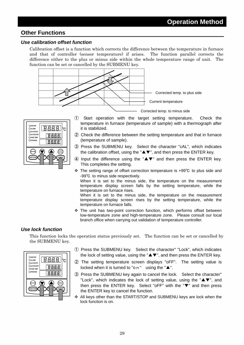
Operation Method Other Functions Use calibration offset function
Calibration offset is a function which corrects the difference between the temperature in furnace and that of controller (sensor temperature) if arises. The function parallel corrects the difference either to the plus or minus side within the whole temperature range of unit. The function can be set or cancelled by the SUBMENU key.
① Start operation with the target setting temperature. Check the temperature in furnace (temperature of sample) with a thermograph after it is stabilized.
② Check the difference between the setting temperature and that in furnace (temperature of sample).
③ Press the SUBMENU key. Select the character "cAL", which indicates the calibration offset, using the "▲▼", and then press the ENTER key.
④ Input the difference using the "▲▼" and then press the ENTER key. This completes the setting.
The setting range of offset correction temperature is +99℃ to plus side and -99℃ to minus side respectively. When it is set to the minus side, the temperature on the measurement temperature display screen falls by the setting temperature, while the temperature on furnace rises. When it is set to the minus side, the temperature on the measurement temperature display screen rises by the setting temperature, while the temperature on furnace falls.
The unit has two-point correction function, which performs offset between low-temperature zone and high-temperature zone. Please consult our local branch office when carrying out validation of temperature controller.
Use lock function This function locks the operation status previously set. The function can be set or cancelled by the SUBMENU key.
① Press the SUBMENU key. Select the character" "Lock", which indicates the lock of setting value, using the "▲▼", and then press the ENTER key.
② The setting temperature screen displays "oFF". The setting value is locked when it is turned to "on" using the "▲".
③ Press the SUBMENU key again to cancel the lock. Select the character" "Lock", which indicates the lock of setting value, using the "▲▼", and then press the ENTER key. Select "oFF" with the "▼" and then press the ENTER key to cancel the function.
All keys other than the START/STOP and SUBMENU keys are lock when the lock function is on.
Current temperature
Corrected temp. to plus side
Corrected temp. to minus side

30
Handling Precautions
WARNING! If a problem occurs
If smoke or strange odor should come out of this unit for some reason, turn off the power key right away, and then turn off the circuit breaker and the main power. Immediately contact a service technician for inspection. If this procedure is not followed, fire or electrical shock may result. Never perform repair work yourself, since it is dangerous and not recommended.
Substances that cannot be used
Never use explosive substances, flammable substances and substances that include explosive or flammable ingredients in this unit. Explosion or fire may occur. (Refer to page45 "List of Dangerous Substances".)
CAUTION! Do not step on this unit
Do not step on this unit. It will cause injury if this unit fall down or break.
Do not put anything on this unit
Do not put anything on this unit. It will cause injury if fall.
Prevention of burn
After an operation, the oven unit and the inside of door, samples have a high temperature for a while. For prevent a burn, be careful that do not touch to the parts in the above when handling samples.
During a thunder storm
During a thunderstorm, turn off the power key immediately, then turn off the circuit breaker and the main power. If this procedure is not followed, fire or electrical shock may be caused.
About the amount of samples
If the excessive amount of sample is set, it could be impossible to control the temperature normally. To keep the temperature control accuracy, do not use this unit in overload.
Return after power failure
When power is supplied after a power failure, the device automatically starts operation again with the same state as just before the power failure. It is danger that the device starts unattached operation after a power failure. We recommend for you to turn off the switch of this unit if a power failure occurs during operation.
In-oven temperature
This unit uses a cooling fan to prevent an over temperature of its outer surface during operation when the earth leakage breaker is turned ON. Do not turn OFF the interrupter, or do not disconnect the power supply plug directly when the in-oven temperature is 600℃ or more after operation, except in the case of emergency.
Provide ventilation at the first operation
This unit exhausts smoke and smell due to burning of organic matters in the furnace when it is used for the first time. This is not abnormal, but ventilating inside the room should be done.
31
Handling Precautions
Furnace may be cracked
Though the furnace may be cracked when it is used with high temperature, this does not affect the use or performance of this unit.
Open/close door in high temperature affects the device
Do not open/close the door as possible at the in-oven temperature of 500℃ or more, which affects the lives of sensor, oven and heater. Quickly open/close it after operation if necessary.
Do not leave door open for a long time at high temperature
Leaving the door open for long time at high temperature may cause a radiation heat, which could result in breakdown on the operation panel or controller.
Fine powder may fly
This unit uses an iron chrome heater. Fine powder from its protective film (oxide film) is possible to be flown during operation. Protect the sample with a cover if needed.
Make protective film on heater
The heater used on this unit forms a protective film on its surface under high temperature. Make the film by operating this unit for ten hours at the temperature of 1050℃ when using it under the temperature of 700℃ or less.
Heater corrosion
The heater used on this unit can be corroded with halogen elements such as chlorine, fluorinate or alkali metals such as sodium or potassium. Do not contact these materials to the heater.
Sensor deterioration
The sensor on this unit (R thermocouple) is very sensitive. Do not contact it to samples when loading or unloading them. Do not touch the sensor with bare hands, which may cause the degradation.
Sensor corrosion
The sensor used on this unit can be corroded at high temperature with reducing substances such as alkali metal, metal steam, metal oxide, carbon monoxide, carbon, phosphorus, selenium or arsenicum or other reducing ambiences. Do not use these materials.
When using N2 gas…
Under the Atmosphere of N2 gas, high temperature nitrides the surface of heater, which prevents the formation of protective film on it. Upper limit temperature for use is, therefore, lower than that under atmospheric air. Use the temperature within the range of 100 to 900℃ when operating this unit under N2 gas.
Notes for overheating prevention device
In case there is a small difference between the set values of temperature for overheating prevention device and that of controller, the overheating prevention device may be activated with displaying Er.07 when the temperature reaches to the set value of controller. Set the temperature of overheating prevention device so it be at least 100℃ or more higher than that of controller.(When the setting temperature is lower, there is a case that overshoot occurs because this unit is high temperature type furnace. This overheating prevention device should be used for protect the unit.)· The default value of the overheating prevention device at factory shipment is 1200℃.
Exhaust device unit
Connect the ground lead to the exhaust device unit with the main body chassis when it installed.
32
Maintenance Method Daily Inspection and Maintenance For the safety use of this unit, please perform the daily inspection and maintenance without fail. Using the city water to this unit might attach dirt. Do inspect and maintain this point while performing daily inspection and maintenance.
WARNING!
• Disconnect the power cable from the power source when doing an inspection or maintenance unless needed.
• Perform the daily inspection and maintenance after returning the temperature of this unit to the normal one.
• Do not disassemble this unit.
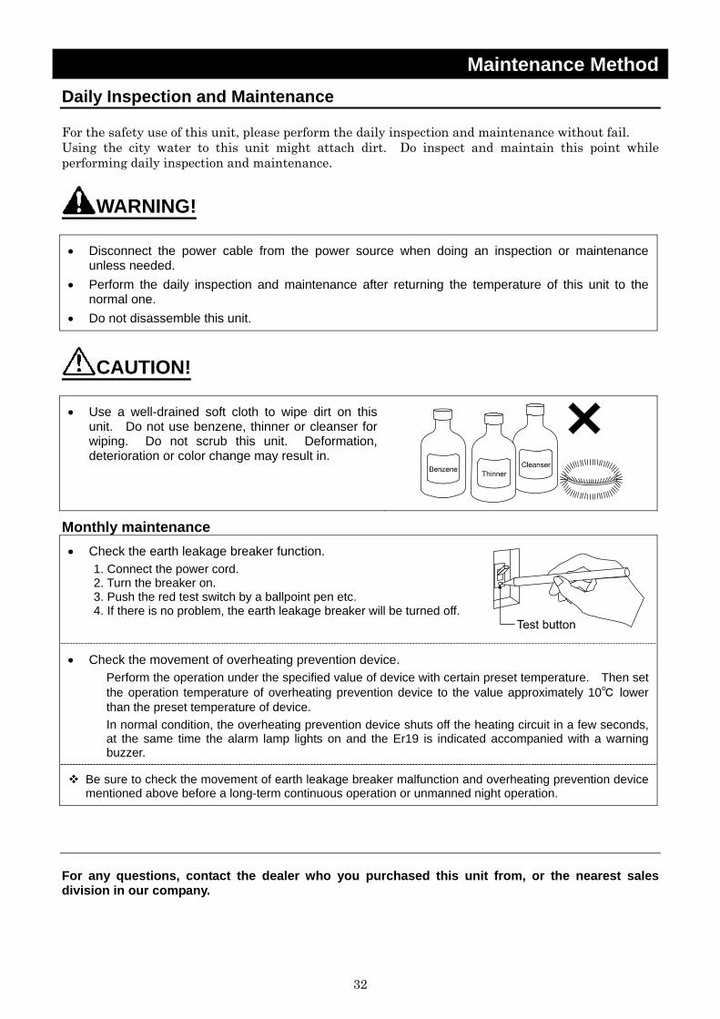
CAUTION!
• Use a well-drained soft cloth to wipe dirt on this unit. Do not use benzene, thinner or cleanser for wiping. Do not scrub this unit. Deformation, deterioration or color change may result in.
Monthly maintenance • Check the earth leakage breaker function.
1. Connect the power cord. 2. Turn the breaker on. 3. Push the red test switch by a ballpoint pen etc. 4. If there is no problem, the earth leakage breaker will be turned off.
• Check the movement of overheating prevention device. Perform the operation under the specified value of device with certain preset temperature. Then set the operation temperature of overheating prevention device to the value approximately 10℃ lower than the preset temperature of device. In normal condition, the overheating prevention device shuts off the heating circuit in a few seconds, at the same time the alarm lamp lights on and the Er19 is indicated accompanied with a warning buzzer.
Be sure to check the movement of earth leakage breaker malfunction and overheating prevention device mentioned above before a long-term continuous operation or unmanned night operation.
For any questions, contact the dealer who you purchased this unit from, or the nearest sales division in our company.

33
Long storage and disposal When not using this unit for long term / When disposing
CAUTION! When not using this unit for long term… • Turn off the power and disconnect the power cord.
WARNING! When disposing… • Keep out of reach of children. • Remove the door and driving parts. • Treat as large trash.
Environmental protection should be considered We request you to disassemble this unit as possible and recycle the reusable parts considering to the environmental protection. The feature components of this unit and materials used are listed below.
Component Name Material
Main body
Body Steel, Melamine, Epoxy composite resin coating, Stainless steel, SUS304
Furnace and Door Ceramic fiber Plates Polyethylene (PET) resin film Electrical Parts Switch, Relays Resin, Copper, and other composites Operation panel Alkyl benzene sulfide (ABS) Board Glass fiber and other composites Heater Iron chrome wire Power code Synthetic rubber coating, Copper, Nickel Wiring Glass fiber, Flame resistance plastic, Copper, Nickel Seals Resin material Sensor (R thermocouple) Platinum element

34
In the Event of Failure… Safety Device and Error Code This unit has an automatic diagnosis function built in the controller and safety devices independent of the controller. The table below shows the cause and the solution method when the safety device operates. Error Code:
When an abnormal condition occurs, an error code appears and the alarm lamp lights in the controller, the buzzer sounds simultaneously. Record the error code and turn off the power of device immediately.
Safety Device Notify Cause/Solution
Sensor trouble detection “ALARM” lamp lights on, “Er.01” appears
• Temperature sensor is broken or disconnected.
• Make a call for service.
SSR short-circuit detection “ALARM” lamp lights on, “Er.02” appears
• Triac is in short-circuit • Make a call for service.
Heater disconnecting detection “ALARM” lamp lights on, “Er.03” appears
• Heater is disconnected. • Make a call for service.
Memory error “ALARM” lamp lights on, “Er.15” appears
• Failure in internal memory. • Make a call for service.
Internal communication error “ALARM” lamp lights on, “Er.17” appears
• Failure in internal communication or temperature inputting circuit.
• Make a call for service.
Overheating “ALARM” lamp lights on, “Er.19” appears
• Overheating prevention device is in operation.
• Reset the power supply, and then adjust the setting temperature of the overheating protection device.
• If the state does not recover, make a call for service.
Measurement temperature error
“ALARM” lamp lights on, “----” appears
• Measurement value is out of display range.
• Make a call for service.
35
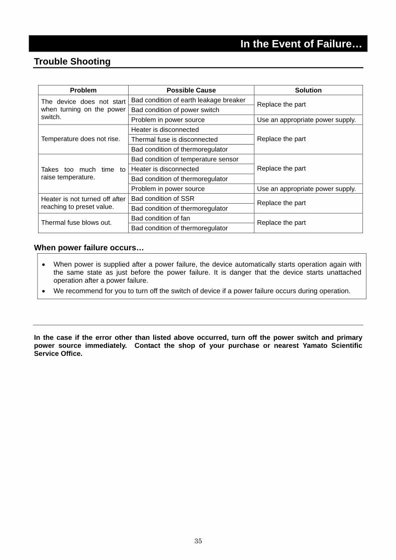
In the Event of Failure… Trouble Shooting
Problem Possible Cause Solution Bad condition of earth leakage breaker Bad condition of power switch
Replace the part The device does not start when turning on the power switch. Problem in power source Use an appropriate power supply.
Heater is disconnected Thermal fuse is disconnected Temperature does not rise. Bad condition of thermoregulator
Replace the part
Bad condition of temperature sensor Heater is disconnected Bad condition of thermoregulator
Replace the part Takes too much time to raise temperature.
Problem in power source Use an appropriate power supply. Bad condition of SSR Heater is not turned off after
reaching to preset value. Bad condition of thermoregulator Replace the part
Bad condition of fan Thermal fuse blows out. Bad condition of thermoregulator
Replace the part
When power failure occurs…
• When power is supplied after a power failure, the device automatically starts operation again with the same state as just before the power failure. It is danger that the device starts unattached operation after a power failure.
• We recommend for you to turn off the switch of device if a power failure occurs during operation.
In the case if the error other than listed above occurred, turn off the power switch and primary power source immediately. Contact the shop of your purchase or nearest Yamato Scientific Service Office.
36
After Service and Warranty In Case of Request for Repair
If the failure occurs, stop the operation, turn OFF the power switch, and unplug the power plug. Please contact the sales agency that this unit was purchased, or the Yamato Scientific's sales office. < Check following items before contact >
◆ Model Name of Product ◆ Production Number ◆ Purchase Date ◆ About Trouble (in detail as possible)
Minimum Retention Period of Performance Parts for Repair
The minimum retention period of performance parts for repair of this unit is 7 years after discontinuance of this unit. The "performance part for repair" is the part that is required to maintain this unit.
See the production plate attached to this unit.
37
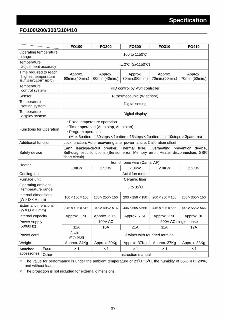
Specification FO100/200/300/310/410 FO100 FO200 FO300 FO310 FO410 Operating temperature range 100 to 1150℃
Temperature adjustment accuracy ±2℃ (@1150℃)
Time required to reach highest temperature @LT:1150℃(@RT:850℃)
Approx. 60min.(40min.)
Approx. 60min.(40min.)
Approx. 70min.(50min.)
Approx. 70min.(50min.)
Approx. 70min.(50min.)
Temperature control system PID control by VS4 controller
Sensor R thermocouple (W sensor) Temperature setting system Digital setting
Temperature display system Digital display
Functions for Operation
・Fixed temperature operation ・Timer operation (Auto stop, Auto start) ・Program operation
(Max 6patterns: 30steps×1pattern, 15steps×2patterns or 10steps×3patterns) Additional function Lock function, Auto recovering after power failure, Calibration offset
Safety device Earth leakage/circuit breaker, Thermal fuse, Overheating prevention device, Self-diagnostic functions (Sensor error, Memory error, Heater disconnection, SSR short circuit)
Iron chrome wire (Cantal AF) Heater 1.0KW 1.5KW 2.0KW 2.0KW 2.2KW
Cooling fan Axial fan motor Furnace unit Ceramic fiber Operating ambient temperature range 5 to 35℃
Internal dimensions (W×D×H mm) 100×150×100 100×250×150 200×250×150 200×250×150 200×300×150
External dimensions (W×D×H mm) 346×405×516 346×405×516 446×505×566 446×505×566 446×555×566
Internal capacity Approx. 1.5L Approx. 3.75L Approx. 7.5L Approx. 7.5L Approx. 9L 100V AC 200V AC single phase Power supply
(50/60Hz) 11A 16A 21A 11A 12A
Power cord 3 wires with plug 3 wires with rounded terminal
Weight Approx. 24Kg Approx. 30Kg Approx. 37Kg Approx. 37Kg Approx. 38KgFuse ×1 ×1 ×1 ×1 ×1 Attached
accessories Other Instruction manual
The value for performance is under the ambient temperature of 23℃±5℃, the humidity of 65%RH±20%, and without load.
The projection is not included for external dimensions.
38
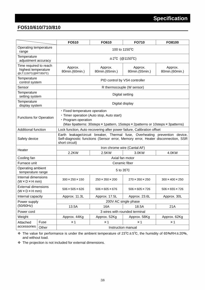
Specification FO510/610/710/810 FO510 FO610 FO710 FO8100 Operating temperature range 100 to 1150℃
Temperature adjustment accuracy ±2℃ (@1150℃)
Time required to reach highest temperature @LT:1150℃(@RT:850℃)
Approx. 80min.(60min.)
Approx. 80min.(65min.)
Approx. 80min.(55min.)
Approx. 80min.(60min.)
Temperature control system PID control by VS4 controller
Sensor R thermocouple (W sensor) Temperature setting system Digital setting
Temperature display system Digital display
Functions for Operation
・Fixed temperature operation ・Timer operation (Auto stop, Auto start) ・Program operation
(Max 6patterns: 30steps×1pattern, 15steps×2patterns or 10steps×3patterns) Additional function Lock function, Auto recovering after power failure, Calibration offset
Safety device Earth leakage/circuit breaker, Thermal fuse, Overheating prevention device, Self-diagnostic functions (Sensor error, Memory error, Heater disconnection, SSR short circuit)
Iron chrome wire (Cantal AF) Heater 2.2KW 2.5KW 3.0KW 4.0KW
Cooling fan Axial fan motor Furnace unit Ceramic fiber Operating ambient temperature range 5 to 35℃
Internal dimensions (W×D×H mm) 300×250×150 250×350×200 270×350×250 300×400×250
External dimensions (W×D×H mm) 506×505×626 506×605×676 506×605×726 506×655×726
Internal capacity Approx. 11.3L Approx. 17.5L Approx. 23.6L Approx. 30L 200V AC single phase Power supply
(50/60Hz) 13.5A 16A 18.5A 21A Power cord 3 wires with rounded terminal Weight Approx. 44Kg Approx. 52Kg Approx. 58Kg Approx. 62Kg
Fuse ×1 ×1 ×1 ×1 Attached accessories Other Instruction manual
The value for performance is under the ambient temperature of 23℃±5℃, the humidity of 65%RH±20%, and without load.
The projection is not included for external dimensions.

39
Specification Optional Accessories
Name Product Code Applied for
Exhaust system unit 100V 214096 FO100/200/300/310
Exhaust system unit 200V 214097 FO310/410/510/610/710/810
Time-up output terminal (*) 200000 All models
Alarm output terminal (*) 200000 All models
Output terminal for measured temperature transmission (4-20mA) 200000 All models
Communication adapter (RS485/RS232C conversion) 200000 All models
N2 gas leading device 200000 All models
Sample tray 200000 All models
Exhaust opening 200000 All models
Either output terminal of the time-up or alarm is available to attach to this unit.
40
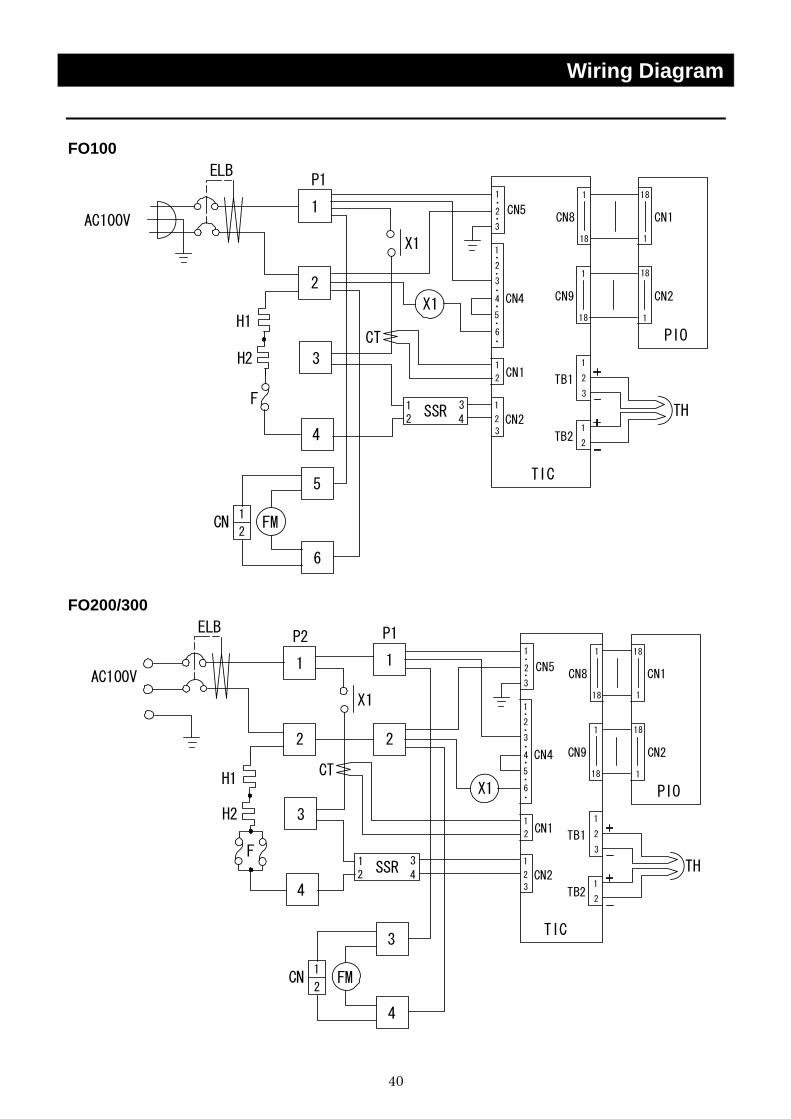
Wiring Diagram FO100
PIO
CN1
1
18
18
11
1
1
1
1
2
3
4
5
2
2
3
6
X1
X1
CN8
SSR12
TB1
TIC
CN5
CN1
CN2
CN4
CT
P1ELB
1
2
F
CN
CN2
1
18
18
1
CN9
3
2
1
2
2
3
4
5
3
H1
AC100V
TB22
1
3
4TH
FM
6
H2
・
・
・
・
・
・
・
・
FO200/300
ELB
AC100V
H1
F
H2
PIO
CN1
1
18
18
11
1
1
1
1
2
3
4
3
2
2
3
6X1
X1
CN8
SSR12
TB1
TIC
CN5
CN1
CN2
CN4
CT
P2
1
2
P1
1
2CN
CN2
1
18
18
1
CN9
3
2
1
2
2
3
4
5
3
TB22
1
3
4TH
FM
4
・
・
・
・
・
・
・
・
41
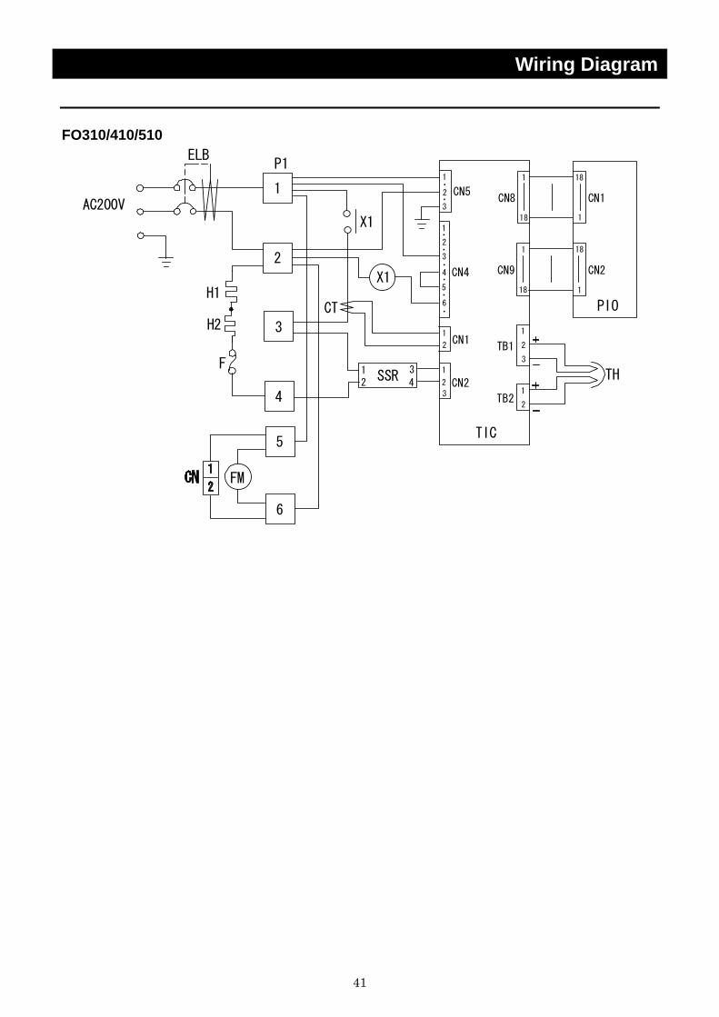
Wiring Diagram FO310/410/510
ELB
F
H1
AC200V
FM
H2
PIO
CN1
1
18
18
11
1
1
1
1
2
3
4
5
2
2
3
6
X1
X1
CN8
SSR12
TB1
TIC
CN5
CN1
CN2
CN4
CT
P1
CN2
1
18
18
1
CN9
3
2
1
2
2
3
4
5
3
TB22
1
3
4TH
6
・
・
・
・
・
・
・
・
42
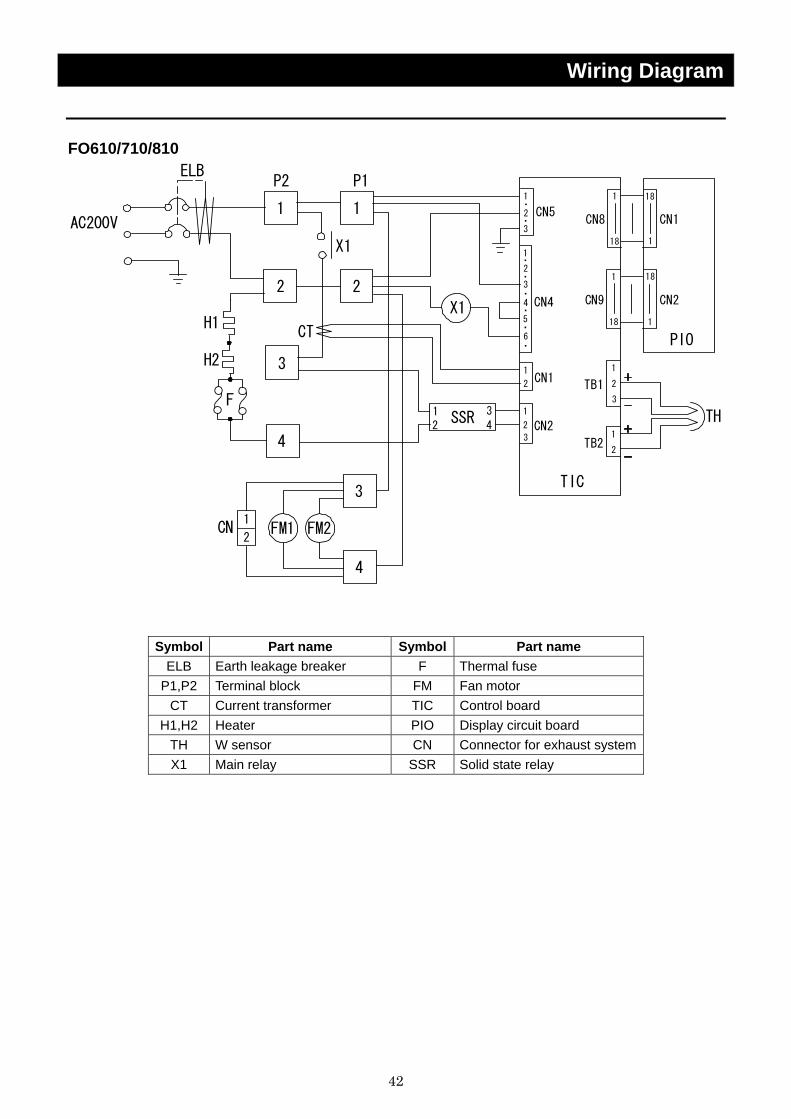
Wiring Diagram FO610/710/810
FM1
ELB
1
2CN
H1
H2
AC200V
F
FM2
PIO
CN1
1
18
18
11
1
1
1
1
2
3
4
3
2
2
3
6
X1
X1
CN8
SSR12
TB1
TIC
CN5
CN1
CN2
CN4
CT
P2
1
2
P1
CN2
1
18
18
1
CN9
3
2
1
2
2
3
4
5
3
TB22
1
3
4TH
4
・
・
・
・
・
・
・
・
Symbol Part name Symbol Part name ELB Earth leakage breaker F Thermal fuse
P1,P2 Terminal block FM Fan motor CT Current transformer TIC Control board
H1,H2 Heater PIO Display circuit board TH W sensor CN Connector for exhaust system X1 Main relay SSR Solid state relay
43
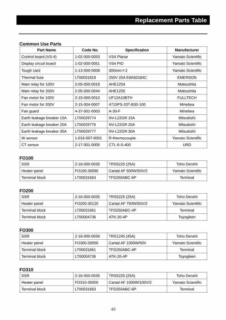
Replacement Parts Table
Common Use Parts Part Name Code No. Specification Manufacturer
Control board (VS-4) 1-02-000-0053 VS4 Planar Yamato Scientific
Display circuit board 1-02-000-0051 VS4 PIO Yamato Scientific
Tough card 1-13-000-0008 300mm×2 Yamato Scientific
Thermal fuse LT00031819 250V 25A E8A50184C EMERSON
Main relay for 100V 2-05-000-0019 AHE1254 Matsushita
Main relay for 200V 2-05-000-0044 AHE1255 Matsushita
Fan motor for 100V 2-15-000-0010 UF12A10BTH FULLTECH
Fan motor for 200V 2-15-004-0007 4715PS-20T-B30-100 Minebea
Fan guard 4-37-001-0003 A-30-F Minebea
Earth leakage breaker 15A LT00029774 NV-L22GR 15A Mitsubishi
Earth leakage breaker 20A LT00029776 NV-L22GR 20A Mitsubishi
Earth leakage breaker 30A LT00029777 NV-L22GR 30A Mitsubishi
W sensor 1-016-007-0001 R-thermocouple Yamato Scientific
CT sensor 2-17-001-0005 CTL-6-S-400 URD
FO100 SSR 2-16-000-0035 TRS5225 (25A) Toho Denshi
Heater panel FO100-30090 Cantal AF 500W/50V/2 Yamato Scientific
Terminal block LT00031663 TFD250ABC-6P Terminal
FO200 SSR 2-16-000-0035 TRS5225 (25A) Toho Denshi
Heater panel FO200-30120 Cantal AF 750W/50V/2 Yamato Scientific
Terminal block LT00031661 TFD250ABC-4P Terminal
Terminal block LT00004736 ATK-20-4P Toyogiken
FO300 SSR 2-16-000-0036 TRS1245 (45A) Toho Denshi
Heater panel FO300-30050 Cantal AF 1000W/50V Yamato Scientific
Terminal block LT00031661 TFD250ABC-4P Terminal
Terminal block LT00004736 ATK-20-4P Toyogiken
FO310 SSR 2-16-000-0035 TRS5225 (25A) Toho Denshi
Heater panel FO310-30000 Cantal AF 1000W/100V/2 Yamato Scientific
Terminal block LT00031663 TFD250ABC-6P Terminal

44
Replacement Parts Table
FO410 Part Name Code No. Specification Manufacturer
SSR 2-16-000-0035 TRS5225 (25A) Toho Denshi
Heater panel LT00013749 Cantal AF 1100W/100V/2 Yamato Scientific
Terminal block LT00031663 TFD250ABC-6P Terminal
FO510 SSR 2-16-000-0035 TRS5225 (25A) Toho Denshi
Heater panel LT00013750 Cantal AF 1250W/100V/2 Yamato Scientific
Terminal block LT00031663 TFD250ABC-6P Terminal
FO610 SSR 2-16-000-0035 TRS5225 (25A) Toho Denshi
Heater panel FO610-30120 Cantal AF 1500W/100V/2 Yamato Scientific
Terminal block LT00031661 TFD250ABC-4P Terminal
Terminal block LT00004736 ATK-20-4P Toyogiken
FO710 SSR 2-16-000-0035 TRS5225 (25A) Toho Denshi
Heater panel FO710-30120 Cantal AF 1750W/100V/2 Yamato Scientific
Terminal block LT00031661 TFD250ABC-4P Terminal
Terminal block LT00004736 ATK-20-4P Toyogiken
FO810 SSR 2-16-000-0036 TRS1245 (45A) Toho Denshi
Heater panel FO810-30090 Cantal AF 2000W/100V/2 Yamato Scientific
Terminal block LT00031661 TFD250ABC-4P Terminal
Terminal block LT00004736 ATK-20-4P Toyogiken

45
Reference List of Dangerous Substances
Never use explosive substances, flammable substances and substances that include explosive or flammable ingredients in this unit.
EXPLOSIVE
Ethylene glycol dinitrate (nitro glycol), Glycerin trinitrate (nitroglycerine), Cellulose nitrate (nitrocellulose), and other explosive nitrate esters
Trinitrobenzene, Trinitrotoluene, Trinitrophenol (picric acid), and other explosive nitro compounds
EXPLOSIVE:
Acetyl hidroperoxide (peracetic acid), Methyl ethyl ketone peroxide, Benzyl peroxide, and other organic peroxides
FLAMMABLE
IGNITING:
Lithium (metal), Potassium (metal), Sodium (metal), Yellow phosphorus, Phosphorus sulfide, Red phosphorus, Celluloid compounds, Calcium carbide, Lime phosphate, Magnesium (powder), Aluminum (powder), Powder of metals other than magnesium and aluminum, Sodium hydrosulfite
Potassium chlorate, Sodium chlorate, Ammonium chlorate, and other chlorate
Potassium perchlorate, Sodium perchlorate, Ammonium perchlorate, and other perchlorate
Potassium peroxide, Sodium peroxide, Barium peroxide, and other inorganic peroxide
Potassium nitrate, Sodium nitrate, Ammonium nitrate, and other nitrate
Sodium chlorite and other chlorites
OXIDIZING:
Calcium hypochlorite and other hypochlorites
Ethyl ether, Gasoline, Acetaldehyde, Propylene chloride, Carbon disulfide, and other flammable substances having a flash point of lower than -30℃
Normal hexane, ethylene oxide, acetone, benzene, methyl ethyl ketone, and other flammable substances having a flash point of -30℃ or higher but lower than 0℃
Methanol, Ethanol, Xylene, Pentyl acetate (amyl acetate), and other flammable substances having a flash point of 0℃ or higher but lower than 30℃
INFLAMMABLE LIQUID:
Kerosene, Light oil (gas oil), Oil of turpentine, Isopentyl alcohol (isoamyl alcohol), Acetic acid, and other flammable substances having a flash point of 30℃ or higher but lower than 65℃
FLAMMABLE GAS:
Hydrogen, Acetylene, Ethylene, Methane, Propane, Butane, and other flammable substances which assume a gaseous state at 15℃ and 1 atm
(Source: Appendix Table 1 of Article 6 of the Industrial Safety and Health Order in Japan)
46
Responsibility Please follow the instructions in this document when using this unit. Yamato Scientific has no responsibility for the accidents or breakdown of device if it is used with a failure to comply. Never conduct what this document forbids. Unexpected accidents or breakdown may result in.
Note
◆ The contents of this document may be changed in future without notice. ◆ Any books with missing pages or disorderly binding may be replaced.
Instruction Manual for Muffle Furnace Model FO100/200/300/310/410/510/610/710/810 Third Edition Oct. 7, 2009 Revised Feb. 2, 2012
Yamato Scientific Co., Ltd.2-1-6 Nihonbashi Honcho, Chuo-ku,
Tokyo, 103-8432, Japanhttp://www.yamato-net.co.jp


![取扱説明書 [F-08A]](https://static.fdocuments.us/doc/165x107/61cef48b0337c2187175b613/-f-08a.jpg)
