.. 0 Manuals/Engineering change report... · Automatic Rifle versions due to the fact that the bolt...
62
STONER 63A WEAPON SYSTEM ..____ __ 0 P.O. BOX 3806 • OETR.OIT S, MICHIGAN
Transcript of .. 0 Manuals/Engineering change report... · Automatic Rifle versions due to the fact that the bolt...

STONER 63A
WEAPON SYSTEM
..____ __ 0 P.O. BOX 3806 • OETR.OIT S, MICHIGAN

REPORT ON ENGINEERING DESIGN CHANGES TO STONER 63 WEAPON SYSTEM
I INTRODUCTION
This report is being published to familiarize all
interested agencies and organizations with the engin-
eering design changes made to the Stoner 63 Weapon System.
Hereafter the new designation for the Stoner 63 Weapon
System will be Stoner 63A Weapon System.
II BACKGROUND
The Stoner 63 Weapon System has been undergoing
tests and evaluations since August 1963 when ARPA/AGILE
evaluated the Stoner 63 Machine Gun, caliber .223 or
5.56mm. Approximately 2400 Stoner 63 Weapons of various
configurations have been manufactured to date.
The United States Marine Corps, United States Army,
and the United States Air Force have conducted Engineering,
Service, and Troop tests to determine the Stoner 63 Weapon
System's military potential. Test reports are presently
CRDIURC GRGE Ct:IMPRNY ____ __.
P. 0. BOX 3806 • DETROIT 5, MICHIGAN

Page 2 of 19
being processed relative to the results of the latest
tests.
The results of these tests indicated that certain
desirable characteristics were lacking in the Stoner 63
Weapon System, and certain deficiencies required correc
tion. Modifications were made to the System to correct
these deficiencies and further modifications were made to
improve the Stoner 63 Weapon System's reliability as a
function of normal product improvement.
III DISCUSSION OF MODIFICATIONS
a. Stoner 63A Rifle
Figures 1 and 2 illustrate the difference
between the Stoner 63 Assault Rifle and the Stoner
63A Rifle. A small arrow points to each modification
made. Close-up pictures of each modification are
shown, and the modifi.cation is discussed below.
Figure 3 shows two types of buttstock pads,
the two piece pad was replaced by a one piece pad
P. 0. BOX 3eOEi • DEi~OIT 5, MICHIGAN

--~T'I'~;;c.
RIGHT SIDE VIEW
STONER 6 3A RIFLE
STONER 63 ASSAULT RIFLE
FIGURE 1


STONER 63 WEAPON SYSTEM BUTT STOCK PAD
TWO PIECE BUTT STOCK PAD (OBSOLETE)
ONE PIECE BUTT STOCK PAD (STANDARD)
FIGURE 3

Page 3 of 19
which, when attached to the buttstock, affords the
System a buttstock pad that will not come off during
use in the field or on the rifle range. This new one
piece pad is made of harder material, and is capable
of being bonded to the stock more securely than the
two piece pad.
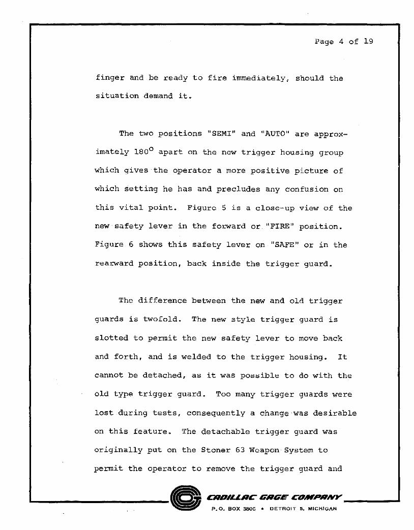
Figure 4 is a photograph of two trigger housing
groups. The upper trigger group in the picture
illustrates the new type which has two positions for
the selector lever. "SEMI" and "AUTO". "SAFE"
position has been removed and a new type safety lever
added which functions much like the safety lever on
the M-1 and M-14 rifles. The trigger housing group
utilized heretofore is shown at the bottom of the
picture. The selector lever had three positions,
"SAFE", "SEMI", and "AUTO". The operator in most
instances had to remove his finger from the trigger
to move the selector lever to either "SEMI" or "AUTO"
from "SAFE" in order to fire the weapon at a target.
With the new safety lever, the operator needs only
to push the safety lever forward with his trigger
._ _______________ @<:>$. c:.':.'::::~ ~':~:,~::::~~ ______ ..

STONER 63A TRIGGER HOUSING. GROUP
STONER 63 TRIGGER HOUSING GROUP (OBSOLETE) '~
Page 4 of 19
finger and be ready to fire immediately, should the
situation demand it.
The two positions "SEMI" and "AUTO" are approx
imately 180° apart on the new trigger housing group
which gives the operator a more positive picture of
which setting he has and precludes any confusion on
this vital point. Figure 5 is a close-up view of the
new safety lever in the forward or "FIRE" position.
Figure 6 shows this safety lever on "SAFE" or in the
rearward position, back inside the trigger guard.
The difference between the new and old trigger
guards is twofold. The new style trigger guard is
slotted to permit the new safety lever to move back
and forth, and is welded to the trigger housing. It
cannot be detached, as it was possible to do with the
old type trigger guard. Too many trigger guards were
lost during tests, consequently a change was desirable
on this feature. The detachable trigger guard was
originally put on the Stoner 63 Weapon System to
permit the operator to remove the trigger guard and
L-------0 P. 0. BOX 3806 • DETROIT 5, MICHIGAN
CRDILI.RC GRGE C#IWPRNY ____ .....

~,,,,.o<'"'
' ' '
·~ SAFETY FORWARD
IN "FIRE" POSITION
STONER 63A RIFLE EJECTION PORT COVER
OPEN
FIGURE 5

SAFETY TO REAR IN "SAFE" POSITION
STONER 63A RIFLE EJECTION PORT COVER
FIGURE 6
ee

Page 5 of 19
be able to fire the weapon with an arctic mitten on.
The new type trigger guard cannot be removed, con-
sequently a winter trigger attachment is necessary
to provide the operator the same capability. Figure
7 shows one type of attachment that is being evaluated.
Figure 5 also shows the ejection port cover in
the open position. This cover has been added to the
Stoner 63A Weapon System to promote greater relia-
bility during extended field operations where the
operator cannot clean his weapon readily. This
feature is especially helpful on the Machine Gun and
Automatic Rifle versions due to the fact that the
bolt is in the rearward position when ready to fire,
consequently the ejection port is open permitting
dirt and dust ready access to the inside parts of the
weapon. The cover can be closed as illustrated in
figure 6, during use in any situation. When the bolt
goes forward it automatically opens the cover to permit
ejection of the spent cartridge. The operator must
manually close it to continue obtaining further bene-
fits of this feature •
..__ ___ 0 CRD,LLRC GRGE COM.PRNY _____ ,.. .
P. 0, BOX 3806 • DETROIT 5, MICHIGAN


Page 6 of 19
This ejection port cover is a result of this
Company's product improvement effort, and is incorp-
orated on all configurations of the Stoner 63A
Weapon System.
During extended field exercises and tests, both
at night and during the daytime, it was obvious that
the insertion of the ammunition magazine into the
weapon required some skill and training to accomplish
quickly. Figure 8 depicts the new style magazine well
that solves this problem. The magazine well is ex
tended and flared to facilitate the insertion of the
magazine into the weapon quickly. The flared portion
acts as a guide for insertion of the magazine into its
proper place.
Figure 9 illustrates the Stoner 63A and Stoner 63
Rifle and Carbine Cocking Handle. The new type cocking
handle is located on top of the receiver which permits
the operator to charge the weapon with either hand
without undue effort. The new type Rifle and Carbine
cocking handle has a feature incorporated in it, that
CRDIURC' GRGE C'DMPRNY ____ __,
P. 0. BOX 3806 • DETROIT 5, MICHIGAN

_..... - ·~ l':l· E-t
~ ~ ~ 8 Ul E-t· ctl E-t !l:l. Ul Ul :>l ; 0 .......
gj [i"ji-=1 .......
0~ ...., .:( 8 ...., il«l':l \C) \C) H Ul
0:: ll«' 2~ 0::
~ ~ H ~ E-t E-t Ul Ul

;~
COCKING HANDLE FOR RIFLE & CARBINE
FIGURE 9
OLD

Page 7 of 19
permits the operator to push the bolt forward if
necessary. This is done by pulling back the handle to
the point where it becomes engaged with the piston rod,
and then pushing the plunger inside the cocking handle
down. Then, while keeping it down, push forward to assist
the bolt to close. Figure 10 shows a close-up view of
this added feature.
Engagement contact area of the new type cocking
handle with the piston rod has been increased. The
old type cocking handle became disengaged from the
piston rod on occasion due to the small contact area.
Figure 11 illustrates the changes made to the
gas cylinder. To increase the service life of this
critical item, the d~ameter of the gas cylinder for
ward of the barrel guide, was increased. The material
was changed to 17-4 PH stainless steel.
During the extensive testing conducted in the
field and laboratories, it became evident that the
piston rod would "freeze up" in the gas cylinder when
...___ __ 0 P. 0. BOX 3806 • DETROIT S, MICHIGAN
CRDIURC GRGE C'OMPRNY ____ __.

MACHINE GUN FORESTOCK MOUNTING PLI\.TE
BOLT FORWARD ASSIST PLUNGER
RIFLE AND CARBINE . COCKING HANDLE
FIGURE 10

.062 INCH WALL THICKNESS
• 09 3 INCH WALL THICKNESS
GAS CYLINDER STEEL (4130)
(OBSOLETE)
BARREL GUIDE
GAS CYLINDER STAINLESS STEEL (17-4 PH)
(STANDARD)
.~
FIGURE
...

Page 8 of 19
carbon build-up reduced the clearance between the
piston head and the gas cylinder. Figure 12 shows
the carbon relief groove inside the gas cylinder
which eliminates this problem, and permits the weapon
to be fired over a longer period of time without being
cleaned.
The Stoner Weapon System barrels have been
hardened by an additional manufacturing process which
will provide the barrel with a harder chamber, bore,
and outside surface. This prevents malfunctions due
to the fact that sand and/or dirt entering the chamber
will imbed itself in the cartridge case instead of the
chamber walls. It prolongs the life of the barrel
tremendously and retards corrosion throughout the
outside and inside surfaces when utilized in a warm,
high humidity environment.
Recent tests at Springfield Armory on two of the
hardened Machine Gun barrels that were fired at a rate
of 200 rounds per minute for th~ minutes without ,
~/, §"::::t:::~,:=-----..1 P. 0. BOX :3606 • DETROIT 5, MICHIGAN


Page 9 of 19
can be fired before the barrel becomes unserviceable.
Under a less rigid schedule a longer life can be ex
pected. The previous barrel became unserviceable,
firing the same schedule, after approximately 8,000
rounds.
b. Stoner 63A Carbine
Figure 13 shows the Stoner 63 Carbine before and
after modifications. All modifications discussed in
paragraph a. above are applicable to this weapon with
the addition of the folding stock which is discussed
below.
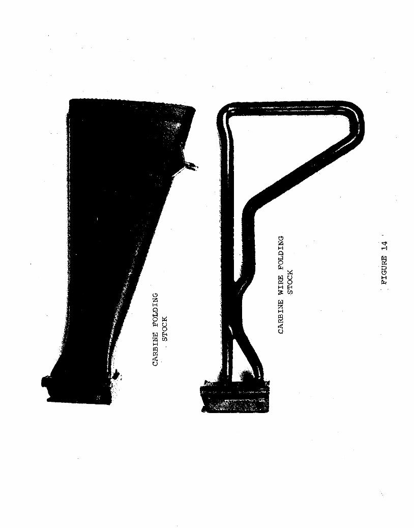
Figure 14 illustrates the two folding stocks
available. The standard folding stock is fabricated
out of 22 parts. The wire folding stock consists of
14 parts and is flat against the receiver when folded.
The polyvinyl chloride coating on the wire stock eli
minates the cold metal contact with the operator's
face and helps deaden noise during movement through
underbrush.
CRDILI.RC GRGE CDMPRNY _____ ...
P. 0. BOX 3606 • DETROIT 5, MICHIGAN

C"l .-I
fil / ~ l z 1-i H·
til. t? til 1-i tS. "" tS
C"l ~ <.O· <.0
"" p:; ~· § 0 E-!
' -~ ,(I) E-t U)
~
"" <!' H .-1 Q s ""
fi1 [i];:.::
" Hg
8
~~
H
"" z H 0 s
lil z
""g H
~ lilE-<
.:t: u
Z<ll H
~ .:t: u

Page 10 of 19
c. Stoner 63A Automatic Rifle
Figure 15 depicts the Stoner 63 Automatic Rifle
before and after modifications. The modifications
are pointed out by small arrows.
Figure 16 shows the old and new magazine adapter
assembly. The new one is extended and flared to faci
litate loading the magazine. The flared extension acts
as a guide and permits rapid reloading day or night.
Figure 17 shows the new and old cocking handles.
The new cocking handle has a more positive engagement
with the piston rod than the old cocking handle. It
also has its latch spring attached to the front end,
which locks it in the forward position during firing.
The new cocking handle can be disengaged from its
locked position with approximately 10 to 12 pounds
pull as compared to the old cocking handle which re
quired approximately 25 pounds pull.
CRDILLRC GRGE COMPRNY ____ __.
P. 0. BOX 3806 • DETROIT 5, MICHIGAN

fS -~ ~ H 0::
~
::! ~ ,..:]
M ~ ..0
!>:: l'l ~ (§ E-<
..: M ..0 Ul
0::
~ E-< (/)

MAGAZINE ADAPTER ASSEMBLY
STONER 63 ASSEMBLY (OBSOLETE)
STONER 63A ASSEMBLY (STANDARD)
FIGURE 16

MACHINE GUN 'COCKING HANDLE
.. STONER 63A ; (STANDARD)
i STONER 63 i (OBSOLETE)
. FIGURE 17
LATCH SPRING

Page 11 of 19
Figure 18 shows the Stoner 63A Machine Gun
forestock assembly which is also utilized on the
Stoner 63A Automatic Rifle. The new plastic fore
stock will do away with the wooden forestock which
was not durable enough for rough field usage. In
order to assemble this plastic forestock to the
Automatic Rifle and the Machine Gun, the mounting
bracket was relocated and a mounting plate was added.
These modifications are shown in figure 19.
In order to sling the Stoner 63A Automatic
Rifle over your shoulder and carry it at the "Ready"
position, a top sling attaching ring was added to the
front end of the carrying handle rod as shown in
figure 20. All Stoner 63A Weapons can be carried
by the firer in this manner.
The hardened barrel, new type butt stock pad,
safety lever, and selector lever utilized by the
Rifle and Carbine are also used on the Automatic
Rifle.
L-----0 P.O. BOX :3806 *' DETROIT 5, MICHIGAN
CRDIURC GRGE COMPRNY ____ __.


FORE STOCK MOUNTING PLATE
MACHINE GUN FORESTOCK MOUNTING BRACKET
OLD LOCATION
FIGURE 19
· NEW LOCATION

CD
§~ CD
CD
!H'l H:O::
::rl~ ~E;
0 <X:~ N
~ MCD IDZ
:::> H CD ~...:! H jgUl ~ 0 p,
E-<0 tilE-<

Page 12 of 19
d. Stoner 63A Light Machine Gun
Figure 21 depicts the Stoner 63 Light Machine
Guns before and after modifications. The modifi-
cations are pointed out by small arrows.
The feed tray manufactured to date utilized
stamped parts which were welded together. Warping
resulted which required extra processing to insure
reliability of functioning. This tray was susceptible
to damage in the field when not carefully handled. It
had a link guide and a cartridge stop which were attached
to the tray by two small screws and two small holding
pawls. The two hinges were also welded to the tray.
The new feed tray illustrated in figures 22 and
23 is constructed in a solid steel investment casting
in which the hinges and cartridge stop are an integral
part. It has a wide single holding pawl and the link
guide is riveted on. The projection that caused
personnel to bark their knuckles when cocking the
weapon has been eliminated •
....__ __ 0 P. 0. BOX 3805 • DETROIT 5, MICHIGAN
C'RDIURC GRGE C'DMPRNY ____ ......

STONER 63A LIGHT MACHINE GUN
STONER 63 LIGHT MACHINE GL'N
FIGURE 21

STONER 63 (OBSOLETE)
FEED TRAY ASSEMBLY TOP VIEW
.,
FIGURE 22
STONER 63A (STANDARD)

STONER 63 (OBSOLETE)
FEED TRAY ASSEMBLY UNDERSIDE VIEW
.FIGURE 23
STONER 63A (STANDARD)

Page 13 of 19
The feed cover was made of stampings which were
welded together. The stamped cover was functional,
which required extreme flatness and squareness, and
was readily susceptible to damage in .the field. It
had four hinges requiring extreme care in welding
to prevent misalignment of the feed cover to the
receiver. The cover was open in many areas, which
permitted dirt and dust to enter the mechanism during
exercises in the field. Closing this feed cover on
the receiver when the bolt was forward caused dis
tortion and bending, which in turn caused it to mal
function.
The new feed cover shown in figures 24 and 25
is an envelope for the rigid cast parts that include
the front and rear rail for the feed pawl assembly
and the hinges. This cover is so constructed that
all possible entry areas for dirt and dust are closed
off. There is a spring loaded cover over the link
ejection port which opens under the force of the link
being ejected, and closes automatically when firing
ceases. Figure 26 shows the cover in its closed
..___ __ 0 CRD,LLRC IIRIIE COIWPRNY ____ __,
P. 0. BOX 3806 • DETROIT 5, MICHIGAN

.,-·---,.,!{ ~
FEED COVER ASSEMBLY TOP VIEW
FIGURE 24

STONER 63A (STANDARD)
STONER 63 (OBSOLETE)
/
PZ!iG W 2££ U ; M ':'-'1"'
FIGURE 25
FEED COVER ASSEMBLY UNDERSIDE VIEW

0::
g () z E-!0 O::H OE-! P..H
U) zo \.() 0 p, N H E-! 0 i ()OQ ~\3 ~tl H
Iii
~ H ..:1

p:;
g t)
?;!Z oS P<E-l
H
(5~
I-
. H p.:
('I
E-l uz
t!
~re
0
fi!O
~ H
"'
~ .:I

Page 14 of 19
position and figure 27 shows it open.
Figure 28 depicts the new and old cap carrier
assemblies which afford the Stoner 63A Machine Gun
with the capability of closing the feed cover regard
less of where the bolt is. The roller is mounted on
a frame that is spring loaded and dove-tailed into
the cap carrier to permit vertical movement. When
the cover is closed with the bolt in the forward po
sition, the roller assembly moves down into the cap
carrier slots, and upon the rearward action of the
bolt, it comes up into the feed lever automatically.
This modification was necessary to prevent damage
to the feed lever and feed cover during field use.
Personnel insisted on closing the cover regardless
of the bolt's position unless they were well trained
in the use of the Machine Gun. This modification
will reduce the training time requirement and prevent
damage to the feed cover.
'-----0 CRD,I.LRC GRGE COMPRNY ____ __.
F'. 0. BOX 3806 • DETROIT 5, MICHIGAN

CARRIER, PISTON AND BOLT ASSEMBLY
FIGURE 28
STONER 63 (OBSOLETE) CAP CARRIER ASSEMBLY :
STONER 63A {STANDARD) . CAP CARRIER ASSEMBLY

Page 15 of 19
During the extensive tests conducted by the
United States Army and the United States Marine
Corps, personnel continually barked their knuckles
on a projection on the feed tray when charging the
Machine Gun. To prevent this, the charging handle
was made longer, which required a relocation of the
cocking handle guide as shown in Figure 29. The
man's knuckle is now to the rear of the slight
projection on the feed tray which caused the problem.
This projection has been eliminated on the new tray
which further alleviates this problem.
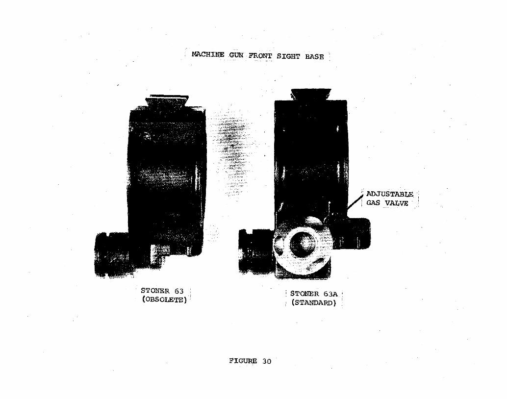
Figure 30 shows the old and new front sight
bases. The new base has been modified by adding a
variable gas port. This variable gas port affords
the operator the capability of decreasing or increasing
the rate of fire, where previously it was not possible
to do this. This modification was necessary to
compensate for the mismatch existing between the
standard 5.56rnm ball cartridge Ml93, and the 5.56mm
tracer cartridge Ml96 .
......._ ___ 0 P. 0. BOX 3906 • DE:TROIT 5, MICHIGAN

' . •' . ~ ~. 6J'· .. ~ .. - i ~ ~ ' -- - ---
FIGURE 29
,:.
NEW LOCATION OF i HANDLE GUIDE II'!
STONER 63 (OBSOLETE)
MACHI~ GUN FRONT SIGHT BASE
FIGURE 30
: STONER 63A : (STANDARD)

Page 16 of 19
The same cocking handle, forestock assembly,
top sling attaching ring, butt stock pad, selector
lever, safety lever, and hardened barrel utilized
by the Automatic Rifle are used by the.Stoner 63A
Light Machine Gun.
e. Stoner 63A Medium Machine Gun
All modifications made on the Stoner 63A Light
Machine Gun and discussed in paragraph d. above, are
applicable to this weapon.
f. Stoner 63A Fixed.Machine Gun
All modifications made on the Stoner 63A Light
Machine Gun and discussed in paragraph c. above are
applicable to the Stoner Fixed Machine Gun where
appropriate.
Figure 31 shows the old and new remote control
assemblies. A modified bell crank assembled to the new
remote control assembly affords the Fixed Machine Gun
with a less sensitive remote control.assembly than that
previously provided.
L-------0 P. 0. BOX 3806 • DETROIT 5, MICHIGAN
CRDI'Ll.RC G'RGE CDMPRNY ____ __.

~~ ~ ... ~--,,<"• ..
",, '-\ ~
'N n. '''i-
' '\; '" ;\\"
-,. \. '• ' '
-~~~~ ~ --:~./ ;r.-:·~~
STONER 63A BELL CRANK (STANDARD)
FIGURE 31
REMOTE CONTROL ASSEMBLY
STONER 63 BELL CRANK (OBSOLETE)

Page 17 of 19
g. Accessories for Stoner 63A Weapon System
Bipod
The bipod has been modified by adding a spring locking
feature that permits the operator to lock the bipod to the
weapon so it cannot become accidently disengaged during
movement through underbrush. Figure 32 shows the old
and new bipod with the new bipod locked in the carrying
position. Figure 33 shows the new and old bipod in
the open position.
Plastic Ammunition Bandoleer
Figure 34 shows the old and new bandoleer. The
new bandoleer is modified by the addition of the metal
reinforced top strip shown in the photograph.
Round Ammunition Drum Container
Figure 35 depicts a 100 round ammunition container
that is hinged and opens by unlatching two snap type
locks. This is quickly detached by removal of two
receiver pins that hold it on the receiver. Figure 36
shows a 150 round ammunition container that opens by
.....__ ___ 0 P. 0. BOX ~806 " DETROIT 5, MICHIGAN
CRDILLRC l'.i'RI'.i'E COIWPRNY ------'


STONER BIPOD
STONER 63 (OBSOLETE)
LOCKING DEVICE
,_,
FIGURE 33
STONER 63A (SorANDARD)

g ... lo: z "'.....
Cl • 2~ :!:~
""' "'"' v.,; o .. ...... - ... :::;
~ z )o ..
s 0
0 z .. 9

U'l M


Page 18 of 19
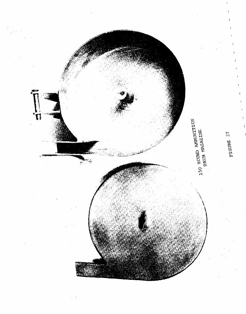
turning the latch in the center 90° counterclockwise
and removing the back plate. Figure 37 depicts this
container with the plate removed.
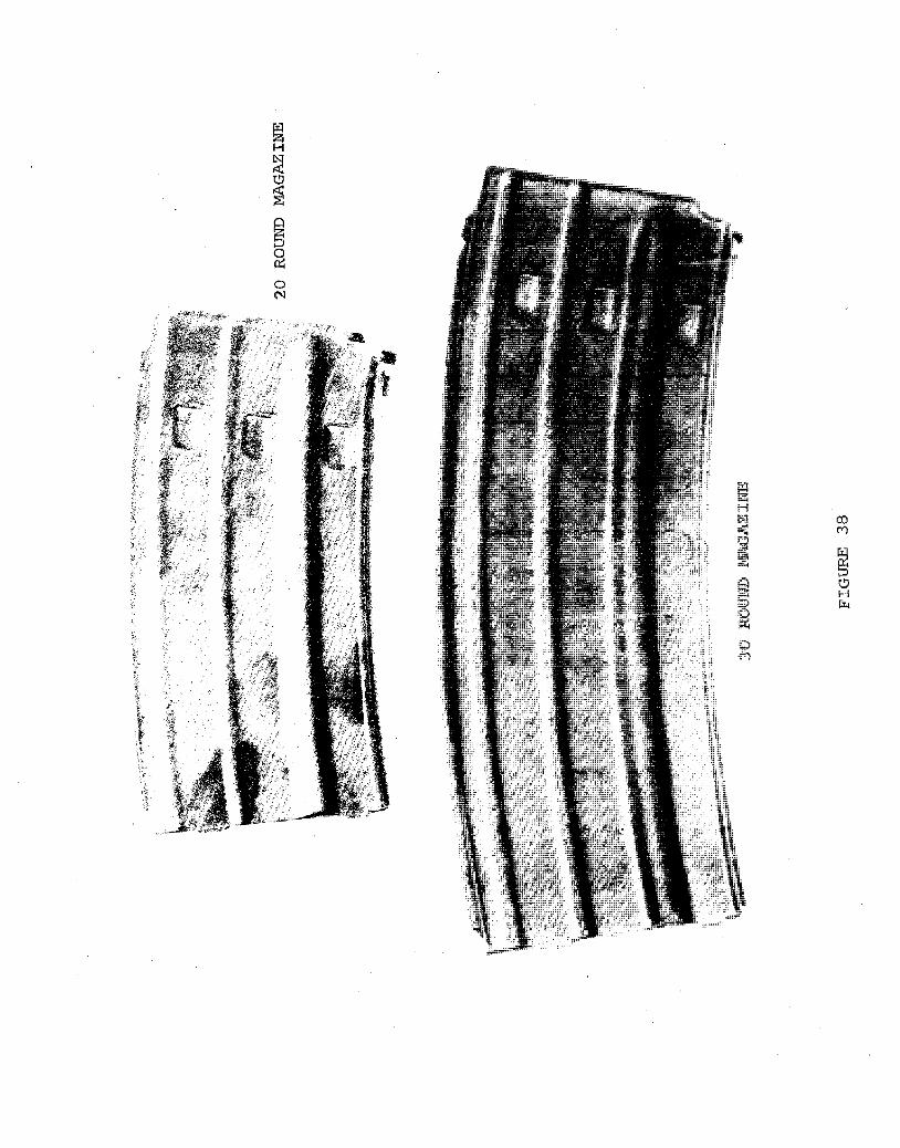
20 Round Magazine
Figure 38 shows a 30 round magazine and a 20
round magazine. The magazine can be made for any
reasonable number of rounds desired. Figure 39 depicts
the steel 30 round magazine on a scale indicating an
8 ounce weight while empty. Figure 40 shows the aluminum
30 round magazine on a scale indicating a weight of 4
ounces, a saving of 4 ounces per magazine.
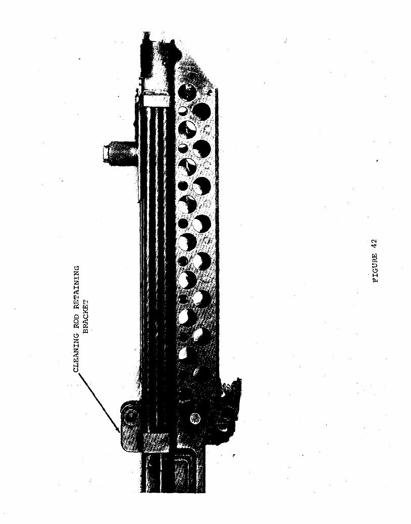
Cleaning Rod Retaining Bracket
Figure 41 shows the cleaning rod retaining bracket
dismounted and Figure 42 shows it attached to the
weapon. The three sections of the cleaning rod are
easily removed for use in the field. The attachment
is removed from the receiver when configured as a Machine
Gun or Automatic Rifle .
..___ __ 0 P. 0. SOX 3806 • DETROIT S, MICHIGAN
-·~. ~tl
0 N
co M

•
-·:~~E~~~ , -'"''J !. ... • li••(P •
. J; .
~


Page 19 of 19
Oiler, Patch and Brush Stowage
The pistol grip will be modified with the addition
of a door so as to make the stowage of the cleaning
gear possible. The door will be hinged and when open
or closed will be retained by its construction. This
feature will offer the individual a means of carrying
the bore brush, bore brush adapter, cleaning rod tip,
combination tool, oiler and cleaning patches on the
weapon for ready access during field operations.
"----0 P. 0. BOX 3806 • DETROIT $, MICHIGAN
CRDIURC GRGE CDIWPRNY ____ __.